1
7.5
7.5.3
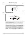
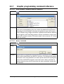
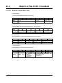
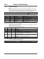
Zero search modes
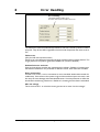
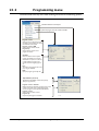
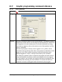
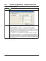
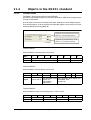
I/O Set Up
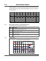
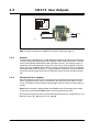
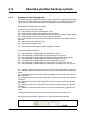
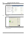
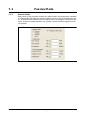
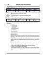
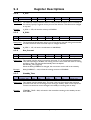
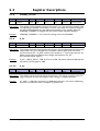
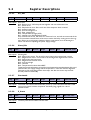
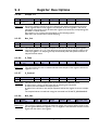
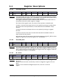
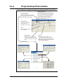
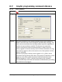
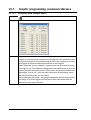
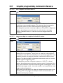
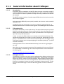
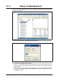
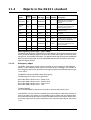
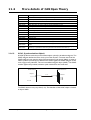
Important information: Each of the 8 pins can be defined as inputs or outputs. The active digital input level for each input is also defined in the above screen. Furthermore, it
is possible to set up a filter for each input to avoid noise interfering with the program.
The inputs for Home, Negative Limit and Positive Limit and outputs for In Position and
Error are also selected here.
If an external encoder is used, it must be enabled here
7.5.4
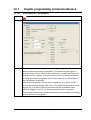
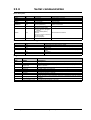
Advanced
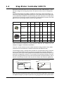
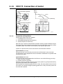
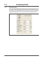
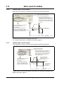
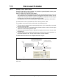
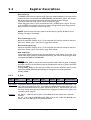
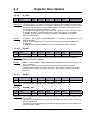
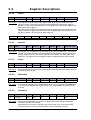
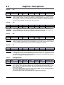
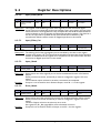
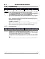
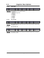
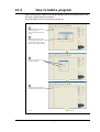
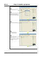
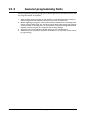
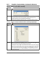
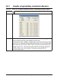
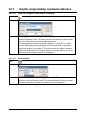
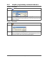
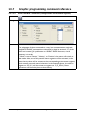
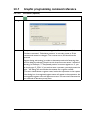
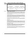
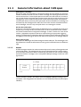
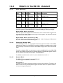
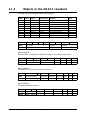
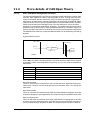
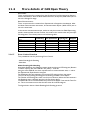
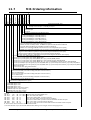
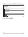
There are several ways to perform a Zero search:
- Start from both sides of the reference sensor in a system with limit switches without
having position limit problems.
- to go to the opposite side of the sensor and use this position as zero position.
- use a position limit as reference position. In this case the zero search position must be
be different from 0 or the motor enters passive mode.
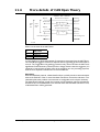
- ignore the reference switch input and use the actual position or index pulse as zero
position before using the zero search position.
JVL Industri Elektronik A/S - User Manual - Integrated Step Motors MIS 231, 232, 234
69