1
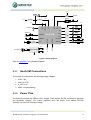
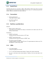
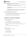
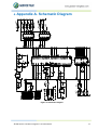
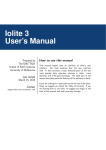
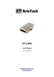
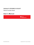
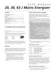
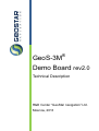
GeoS-3M ® Demo Board rev2.0 Technical Description R&D Center “GeoStar navigation” Ltd. Moscow, 2013 Table of Contents 1. Abbreviations .............................................................................................................................................................................. 4 2. Technical Description ................................................................................................................................................................. 5 2.1. Introduction ......................................................................................................................................................................... 5 2.2. Overall View ......................................................................................................................................................................... 5 2.3. Block Diagram ..................................................................................................................................................................... 5 2.3.1 GeoS-3M Connections ......................................................................................................................................... 6 2.3.2 Power Plan ........................................................................................................................................................... 6 2.3.3 Serial Ports ........................................................................................................................................................... 7 2.3.4 Connectors ........................................................................................................................................................... 7 2.3.5 Switches, pushbuttons ......................................................................................................................................... 7 2.3.6 LEDs .................................................................................................................................................................... 7 2.3.7 Signal Pads .......................................................................................................................................................... 8 2.4. Assembly Drawing .............................................................................................................................................................. 8 3. How to Use the Board ................................................................................................................................................................. 8 3.1. USB Driver ........................................................................................................................................................................... 8 3.2. External Connections ......................................................................................................................................................... 9 3.3. Getting Started. Operation in Full-power Mode................................................................................................................ 9 3.4. Operation in Power-saving Mode .................................................................................................................................... 10 4. Appendix A. Schematic Diagram ............................................................................................................................................. 11 List of Figures Figure 1: General View ................................................................................................................................................................... 5 Figure 2: Block Diagram ................................................................................................................................................................. 6 Figure 3: Assembly Drawing .......................................................................................................................................................... 8 Figure 4: Antenna and USB Connections ..................................................................................................................................... 9 Figure 5: Schematic Diagram ....................................................................................................................................................... 11 © R&D Center “GeoStar navigation” Ltd. 2013-02-25 2 Scope The document is the technical description of the GeoS-3M Demo Board and intended for the users of GPS/GLONASS/SBAS OEM module GeoS-3M. The document contains three chapters and appendix as follows: Chapter 1: list of abbreviations Chapter 2: technical description Chapter 3: how to use the board Appendix A: schematic diagram. © R&D Center “GeoStar navigation” Ltd. 2013-02-25 3 1. Abbreviations DC-DC: IO: LED: LDO: OS: PC: SW: VCP: DC-DC Converter Input Output Light Emission Diode Low Drop Out Linear Regulator Operating System Personal Computer Soft Ware Virtual COM Port © R&D Center “GeoStar navigation” Ltd. 2013-02-25 4 2. Technical Description 2.1. Introduction The Demo Board is the part of GeoS-3 Demo Kit that contains following items: GLONASS/GPS Antenna GeoSDemo3 * PC-based Demo SW GeoS-3M User Manual*. ® * Downloadable from www.geostar-navigation.com. 2.2. Overall View Backup battery Backup battery switch Antenna connector GeoS-3M USB port nRESET pushbutton ON/OFF pushbutton PD pushbutton Figure 1: General View 2.3. Block Diagram The board comprises following main parts: GeoS-3M module DC-DC voltage converters USB port Dual RS232-to-USB data converter Voltage level translators Pushbuttons, connectors, switches LED indicators. © R&D Center “GeoStar navigation” Ltd. 2013-02-25 5 3.3V 3.3V Battery 1.8V LDO DC-DC 5.0V 1PPS ON VBAT 1PPS VDD Antenna VDD_IO V_ANT 3.3V Tx0 Tx1 TX1 Rx0 ON/OFF RX0 GeoS-3M Rx1 RX1 nRESET PD_ACK TX0 USB—RS232 RX0 TX1 RX1 E_PPS PD E_PPS Reset generator E_FRQ PD E_FRQ NRESET Port #0 & #1 3.3V TX0 ON/OFF 5.0V OFF PD_ACK STATUS STATUS 3.3V Figure 2: Block Diagram Refer to Appendix A for schematic diagram. 2.3.1 GeoS-3M Connections The module is connected to the following supply voltages: VDD: 1.8V VDD_IO: 3.3V V_ANT: 3.3V VBAT: on-board battery. 2.3.2 Power Plan The board is powered with USB bus 5.0V voltage. There are two DC-DC converters to generate two secondary voltages: 3.3V (switch regulator) and 1.8V (LDO). Li-Ion battery CR1220 (38mAh) is the source of backup voltage. © R&D Center “GeoStar navigation” Ltd. 2013-02-25 6 Serial Ports 2.3.3 GeoS-3M serial ports are converted to USB in USB—RS232 FT2232 chip (FTDI). The chip’s supply voltage 3.3V comes directly from DC-DC converter output so it is powered right after the board’s USB port is attached to the active USB Host. Connectors 2.3.4 Antenna: antenna port. Type: MMCX female, straight. Port #0 & #1: USB port. Type: mini USB. Switches, pushbuttons 2.3.5 Switches: Battery: backup voltage control. If the switch is set to ON then the battery is connected to the module; when OFF, the battery is disconnected. Pushbuttons: ON/OFF: on/off control. Pushing the button forces the module to “OFF” state. nRESET: manual reset control. Pushing the button forces the module to “RESET” state. PD: wake-up control (PD signal). Pushing the button generates single PD pulse. The signal wakes the module up in FIX® BY-REQUEST power-saving mode. 2.3.6 LEDs 3.3V: power indicator. Continuously lighting if 3.3V is OK. Tx0, Tx1: serial ports transmit data indicators. Flashing if the module sends data. Rx0, Rx1: serial ports receive data indicators. Flashing if the Host sends data to the module. © R&D Center “GeoStar navigation” Ltd. 2013-02-25 7 STATUS: indicator of the module status. Reflects following states of the module: ACQUISITION, POSITIONING, and FALURE. PD_ACK: “ACTIVE”/”SLEEP” indicator. Lighting if the module is in “ACTIVE” state. 2.3.7 Signal Pads The following signals are available at on-board signal pads: E_PPS, E_FRQ, 1PPS. The voltage levels of the signals are referred to 3.3V supply voltage. 2.4. Assembly Drawing Figure 3: Assembly Drawing 3. How 3.1. USB to Use the Board Driver If the board is going to be used with personal computer, it should have USB driver been installed. The driver establishes two virtual COM ports for communicating with GeoS-3M over serial ports. If demo SW GeoSDemo3® is used for evaluating GeoS-3M module then it’s not necessary to install USB driver as USB driver is already integrated into GeoSDemo3® installer. If GeoSDemo3® is not used, USB driver (VCP Driver) should be installed; it is downloadable from the following URL link: http://www.ftdichip.com/Drivers/VCP.htm. © R&D Center “GeoStar navigation” Ltd. 2013-02-25 8 3.2. External Connections The board requires following hardware connections (Figure 4): GLONASS/GPS antenna USB cable for attaching to USB port of the Host PC. For proper communication via USB, USB connections should be done after PC is powered up and operating system is loaded. Figure 4: Antenna and USB Connections The on-board battery provides backup power to the module for arranging warm/hot starts only. 3.3. Getting Started. Operation in Full-power Mode After making hardware connections as described in section 3.2, the module is powered up and starts automatically in full-power mode. On default, Port #0 works on binary protocol, and Port #1 – on NMEA protocol. LED devices behave as follows: 3.3V: constantly lighting Tx0, Tx1: flashing once per second Rx0, Rx1: flashing as soon as the Host is sending data to the module © R&D Center “GeoStar navigation” Ltd. 2013-02-25 9 STATUS: flashing rate depends on current module status: ACQUISITION: period is 2 seconds (1 second on, 1 second off); indicates the module is at signal acquisition phase, and no position fix yet POSITIONING: period is 1 second (0.2 seconds on, 0.8 seconds off); indicates position fix is available FAILURE: period is 0.5 seconds (0.2 seconds on, 0.3 seconds off); indicates the module has found hardware failure, and no position fix can be calculated. PD_ACK: lighting if the module is in “ACTIVE” state. Warm/hot starts can be organized in following ways: If on-board backup battery is OK and Battery switch is on, recycle main power by reconnecting USB port or click ON/OFF or nRESET pushbutton If Battery switch is off, click ON/OFF or nRESET pushbutton. 3.4. Operation in Power-saving Mode In this mode LED devices behave as follows: 3.3V: constantly lighting Tx0, Tx1: flashing as soon as the module is transmitting data Rx0, Rx1: flashing as soon as the Host is sending data to the module STATUS: off in “SLEEP” state; while in “ACTIVE” state, behaves the same way as in fullpower mode PD_ACK: off in “SLEEP” state; lighting in “ACTIVE” state. To quit power-saving mode: Send dedicated message to the module Reconnect USB port Click ON/OFF pushbutton Click nRESET pushbutton. © R&D Center “GeoStar navigation” Ltd. 2013-02-25 10 4. Appendix A. Schematic Diagram Figure 5: Schematic Diagram © R&D Center “GeoStar navigation” Ltd. 2013-02-25 11