1
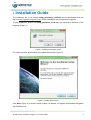
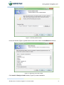
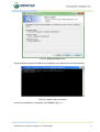
® GeoSDemo3 v3.02 User Manual R&D Center “GeoStar navigation” Ltd. Moscow, 2012 Table of Contents 1. About Program ...................................................................................................................................................................... 5 1.1. Introduction ................................................................................................................................................................... 5 2. Abbreviations ........................................................................................................................................................................ 6 3. Installation Guide .................................................................................................................................................................. 7 4. How to Use........................................................................................................................................................................... 11 4.1. Getting Connection with the Receiver ...................................................................................................................... 11 4.1.1 Detect COM Port Automatically .................................................................................................................... 11 4.1.2 Set COM Ports Manually .............................................................................................................................. 11 4.1.3 Use Last COM Ports Configuration .............................................................................................................. 12 4.1.4 Reading from File ......................................................................................................................................... 12 4.2. Main Window ............................................................................................................................................................... 13 4.3. Channels ...................................................................................................................................................................... 17 4.4. Messages ..................................................................................................................................................................... 18 4.5. Map ............................................................................................................................................................................... 19 4.6. Menu Bar ...................................................................................................................................................................... 22 4.6.1 File ............................................................................................................................................................... 22 4.6.2 Communication ............................................................................................................................................ 22 4.6.3 Settings ........................................................................................................................................................ 23 4.6.3.1 Set Initial Parameters .............................................................................................................................. 23 4.6.3.2 Set Serial Port Parameters ...................................................................................................................... 24 4.6.3.3 Set Operation Mode ................................................................................................................................ 24 4.6.3.4 Set Navigation Task Solution Parameters ............................................................................................... 25 4.6.3.5 Set Output Data Rate .............................................................................................................................. 25 4.6.3.6 DGNSS Control ....................................................................................................................................... 26 4.6.3.7 SBAS Control .......................................................................................................................................... 26 4.6.3.8 Power Save Modes Control ..................................................................................................................... 26 4.6.3.9 Set GPS Almanac .................................................................................................................................... 27 4.6.3.10 Set GLONASS Almanac ..................................................................................................................... 27 4.6.3.11 Set GPS Ephemerides ....................................................................................................................... 28 4.6.3.12 Set GLONASS Ephemerides .............................................................................................................. 28 4.6.3.13 Set PPS Parameters .......................................................................................................................... 28 4.6.3.14 Enable/Disable SV in Position Fix ...................................................................................................... 29 4.6.3.15 Enable/Disable NMEA Messages ....................................................................................................... 29 4.6.3.16 Enable/Disable Binary Messages ....................................................................................................... 29 4.6.3.17 Set Data Protocol Assignment to Serial port ...................................................................................... 30 4.6.4 Queries ......................................................................................................................................................... 31 4.6.5 Commands ................................................................................................................................................... 31 4.6.5.1 Request FW Version ............................................................................................................................... 32 4.6.5.2 Restart Receiver ...................................................................................................................................... 32 4.6.5.3 Save Almanacs to Flash .......................................................................................................................... 32 4.6.5.4 Enter/Quit Power Save Mode .................................................................................................................. 32 4.6.5.5 Switch to NMEA ...................................................................................................................................... 33 4.6.5.6 Request Serial Port Number ................................................................................................................... 33 4.6.5.7 Enable/Disable Antenna Power ............................................................................................................... 33 4.6.5.8 Request Receiver Configuration ............................................................................................................. 33 4.6.5.9 Update FW .............................................................................................................................................. 34 4.6.6 Updates Check ............................................................................................................................................. 35 5. Connecting Software to the Receiver ............................................................................................................................... 37 © R&D Center “GeoStar navigation” Ltd. 2012-10-01 2 List of Figures Figure 1: Installation language select ........................................................................................................................................... 7 Figure 2: Installer start window ..................................................................................................................................................... 7 Figure 3: Choosing install location ............................................................................................................................................... 8 Figure 4: Selecting a start menu folder ......................................................................................................................................... 8 Figure 5: Ready to Install window ................................................................................................................................................. 9 Figure 6: Installing USB driver window ........................................................................................................................................ 9 Figure 7: Installation complete window ...................................................................................................................................... 10 Figure 8: Choosing the way of connection to the receiver ....................................................................................................... 11 Figure 9: main settings window................................................................................................................................................... 12 Figure 10: Main program window ................................................................................................................................................ 13 Figure 11: Brief navigation data panel ........................................................................................................................................ 13 Figure 12: Sky chart ...................................................................................................................................................................... 14 Figure 13: Receiver operation mode indicators panel .............................................................................................................. 14 Figure 14: Diagrams panel ........................................................................................................................................................... 16 Figure 15: Status bar .................................................................................................................................................................... 16 Figure 16: Channels bookmark for binary data .......................................................................................................................... 18 Figure 17: Channels bookmark for NMEA data .......................................................................................................................... 18 Figure 18: Messages bookmark................................................................................................................................................... 19 Figure 19: Displaying position fix on Google Maps ................................................................................................................... 20 Figure 20: Displaying position fix on simplified map ................................................................................................................ 21 Figure 21: Menu Bar...................................................................................................................................................................... 22 Figure 22: File item ....................................................................................................................................................................... 22 Figure 23: Reading from file parameters .................................................................................................................................... 22 Figure 24: Communication item .................................................................................................................................................. 22 Figure 25: Settings list for binary data ........................................................................................................................................ 23 Figure 26: Settings list for NMEA data ........................................................................................................................................ 23 Figure 27: Set initial parameters panel ....................................................................................................................................... 24 Figure 28: Serial port parameters panel ..................................................................................................................................... 24 Figure 29: Operation mode panel ................................................................................................................................................ 24 Figure 30: Navigation task solution parameters panel .............................................................................................................. 25 Figure 31: Output data rate panel ................................................................................................................................................ 25 Figure 32: DGNSS settings panel ................................................................................................................................................ 26 Figure 33: SBAS settings panel ................................................................................................................................................... 26 Figure 34: Power save mode settings panel .............................................................................................................................. 27 Figure 35: GPS almanac panel ..................................................................................................................................................... 27 Figure 36: GLONASS almanac panel .......................................................................................................................................... 27 Figure 37: GPS ephemerides panel ............................................................................................................................................. 28 Figure 38: GLONASS ephemerides panel ................................................................................................................................... 28 Figure 39: PPS parameters panel ................................................................................................................................................ 28 Figure 40: Enable/disable SV panel ............................................................................................................................................. 29 Figure 41: Enable/disable NMEA messages panel..................................................................................................................... 29 Figure 42: Enable/disable binary messages panel .................................................................................................................... 30 Figure 43: Data protocol assignment to serial port panel; Port#0 binary, Port#1 NMEA ....................................................... 30 Figure 44: Other data protocol options ....................................................................................................................................... 30 Figure 45: Queries list for binary data ........................................................................................................................................ 31 Figure 46: Queries list for NMEA data ......................................................................................................................................... 31 Figure 47: Commands item for binary data ................................................................................................................................ 31 Figure 48: Commands item for NMEA data ................................................................................................................................ 31 Figure 49: Displaying receiver FW version and serial number ................................................................................................. 32 Figure 50: Restart receiver panel for binary data ...................................................................................................................... 32 © R&D Center “GeoStar navigation” Ltd. 2012-10-01 3 Figure 51: Restart receiver panel for NMEA data ....................................................................................................................... 32 Figure 52: Power save mode control panel ................................................................................................................................ 32 Figure 53: Switch to NMEA panel ................................................................................................................................................ 33 Figure 54: Antenna power control panel..................................................................................................................................... 33 Figure 55: Browsing the FW file to download ............................................................................................................................ 34 Figure 56: FW update progressing .............................................................................................................................................. 34 Figure 57: File failed message ..................................................................................................................................................... 34 Figure 58: Download failure message......................................................................................................................................... 35 Figure 59: Update complete message ......................................................................................................................................... 35 Figure 60: Updates check............................................................................................................................................................. 35 Figure 61: Info about available updates...................................................................................................................................... 35 Figure 62: No updates available message .................................................................................................................................. 36 Figure 63: Downloading updates progressing ........................................................................................................................... 36 Figure 64: Download complete window ...................................................................................................................................... 36 Figure 65: Automatic COM port scanning .................................................................................................................................. 37 Figure 66: Finding virtual COM port ............................................................................................................................................ 37 Figure 67: Virtual COM port properties ....................................................................................................................................... 38 © R&D Center “GeoStar navigation” Ltd. 2012-10-01 4 Scope The document presents description of how to use demonstration software GeoSDemo3®. The document contains 5 chapters as follow: Chapter 1: about program Chapter 2: abbreviations Chapter 3: installation guide Chapter 4: using software Chapter 5: how to connect software to the receiver. 1. About Program 1.1. Introduction GeoSDemo3® is a demo software for GeoS-3® and GeoS-3M® modules. This is PC based software with intuitive and easy-to-use GUI that could be a helpful instrument for evaluating receiver modules and updating their firmware. Features: Auto scan of connected PC COM ports or manual connection to the receiver serial ports Graphical presentation of output navigation data including user position on Google Maps Displaying receiver hardware status, tracking channels status and current operation mode Allows choosing and sending settings, queries and commands to the receiver Displaying responses to settings, queries and commands Logging output data (both binary and NMEA) to the files on PC hard disc Replay of log files that have been previously recorded Allows receiver firmware update. The software is a Win32 application intended for running on PC with Windows XP™, Windows Vista™ and Windows 7™ operation systems. GUI language: Russian/English. © R&D Center “GeoStar navigation” Ltd. 2012-10-01 5 2. Abbreviations AGC: Az: C/N0: DOP: DR: El: FW: GUI: HEE: PC: PLL: PPS: SNR: SV: SW: UTC: VEE: Auto Gain Control Azimuth Carrier-to-Noise ratio (in 1Hz bandwidth) Dilution of Precision Dead Reckoning Elevation Firmware Graphical User Interface Horizontal Error Estimate Personal Computer Phase Locked Loop Pulse Per Second Signal-to-Noise Ratio Space Vehicle Software Universal Time Coordinated Vertical Error (altitude) Estimate © R&D Center “GeoStar navigation” Ltd. 2012-10-01 6 3. Installation Guide The installation file (in zip format) setup_geosdemo_v3.02.zip can be downloaded from the web site http://geostar-navigation.com. Before installation, the file should be unzipped. To start installation, please run setup_geosdemo_v3.02.exe. The first step is selection of the language (Figure 1). Figure 1: Installation language select For further proceed, please follow the installer instructions (Figure 2). Figure 2: Installer start window Click Next (Figure 3) to choose install location (on default C:\Program files\Geostar-Navigation Ltd.\GeoSDemo3). © R&D Center “GeoStar navigation” Ltd. 2012-10-01 7 Figure 3: Choosing install location In the next window (Figure 4) please select a start menu folder for GeoSDemo3® shortcut. Figure 4: Selecting a start menu folder Click Install in Ready to Install window (Figure 5) to start installation. © R&D Center “GeoStar navigation” Ltd. 2012-10-01 8 Figure 5: Ready to Install window Figure 6 depicts progress of USB driver installation; the window will close automatically. Figure 6: Installing USB driver window As soon as installation is completed, click Finish (Figure 7). © R&D Center “GeoStar navigation” Ltd. 2012-10-01 9 Figure 7: Installation complete window The following shortcut will be created on the PC’s desktop: To run program, double click on the shortcut or go to: Start → Programs → Geostar – Navigation Ltd → GeoSDemo3. © R&D Center “GeoStar navigation” Ltd. 2012-10-01 10 4. How to Use 4.1. Getting Connection with the Receiver How to connect window (Figure 8) is the starting window that provides following options of connecting to the receiver: 1. Automatic scan of the active computer COM or virtual COM ports 2. Manual assignment of specific computer COM port 3. Use of the last active computer ports configuration. In addition, the program can be set to read data from the log file that has been saved previously. This option can be selected by ticking off Reading from file. Figure 8: Choosing the way of connection to the receiver 4.1.1 Detect COM Port Automatically After choosing this option, the program will scan all available computer COM ports automatically in order to detect the ports communicated with the receiver. In case the receiver is connected to PC via USB-to-Serial adapter, USB driver will generate virtual COM port. The number of available COM port or virtual COM port is displayed in the status bar (Figure 10). 4.1.2 Set COM Ports Manually When choosing this option, COM port number and its settings could be set manually Main settings window (Figure 9). © R&D Center “GeoStar navigation” Ltd. 2012-10-01 11 Figure 9: Main settings window In addition, the window provides the options of selecting Google Maps configuration, Lat/Lon format, and enabling/disabling log file. The software creates three types of log files as follows (yyyy – year, mm – month, dd – day, hh – hour, mm – minute, ss – seconds): yyyymmdd-hhmmss.tim yyyymmdd-hhmmss.pr0 (Port #0 data) yyyymmdd-hhmmss.pr1 (Port #1 data). 4.1.3 Use Last COM Ports Configuration When choosing this option, the program will use COM ports configuration that has been already used at previous session. 4.1.4 Reading from File When chosen, the program will be set for reading log files. © R&D Center “GeoStar navigation” Ltd. 2012-10-01 12 4.2. Main Window Main program window (Figure 10) displays six data panels. 1 6 4 2 3 5 Figure 10: Main program window 1. Brief navigation data panel (Figure 11) displays UTC, Latitude/Longitude/Altitude, Geoidal separation, Ground speed, Heading, DOP factors, Horizontal Error Estimate (HEE) and Vertical Error Estimate (VEE). Figure 11: Brief navigation data panel 2. Sky chart (Figure 12). The number inside circle is system SV number. The circle color identifies the satellite system and SV status in following manner: © R&D Center “GeoStar navigation” Ltd. 2012-10-01 13 GPS SVs are blue: dark blue identifies SV being tracked, light blue – used in fix GLONASS SVs are green: dark green identifies SV being tracked, light green – used in fix GPS SVs not in view are pink, GLONASS SVs not in view are red SBAS SVs are olive. Figure 12: Sky chart 3. Receiver operation mode indicators panel (Figure 13). Figure 13: Receiver operation mode indicators panel The panel consists of six indicators which are described in detail in Table 1. © R&D Center “GeoStar navigation” Ltd. 2012-10-01 14 Table 1: Description of receiver operation mode indicators Type View Description Fix not available Fix available and valid Fix indicator Fix available and extrapolated Coordinates hold mode disabled Coordinates hold mode Coordinates hold mode enabled GPS+GLONASS Satellite system GLONASS only GPS only 3D fix 3D/2D 2D fix Receiver has been configured to auto select of diff corrections source and is operating in autonomous mode Receiver has been configured to auto select of diff corrections source and is operating in differential mode Diff mode indicator SBAS enabled; receiver is operating in autonomous mode SBAS enabled; receiver is operating in differential mode RTCM enabled; receiver is operating in autonomous mode RTCM enabled; receiver is operating in differential mode Receiver is operating in full-power mode (RELAXED FIX® enabled but switched off) RELAXED FIX® indicator RELAXED FIX® switched on, “SLEEP” state (the number indicates duration of the state in seconds) RELAXED FIX® switched on, “ACTIVE” state (the number indicates duration of the state in seconds) Receiver is operating in full-power mode (FIX-BY-REQUEST® enabled but switched off) FIX-BY-REQUEST® indicator FIX-BY-REQUEST® switched on, “SLEEP” state (the number indicates duration of the state in seconds) FIX-BY-REQUEST® switched on, “ACTIVE” state (the number indicates duration of the state in seconds) 4. Diagrams panel: Latitude/Longitude, Altitude, Ground speed (Figure 14). © R&D Center “GeoStar navigation” Ltd. 2012-10-01 15 Figure 14: Diagrams panel Each chart displays 300 points only, after that the data is cleared. To clear charts manually, double click Latitude/Longitude diagram. 5. Status bar (Figure 15). Figure 15: Status bar There are eight indicators in the bar with functions described in Table 2. © R&D Center “GeoStar navigation” Ltd. 2012-10-01 16 Table 2: Functions of status bar indicators Type View Description No data on Port #0 Receiver’s Port #0 status Communication on Port #0 active. Displayed: protocol type (binary)/СОМ port number/baud rate No data on Port #1 Receiver’s Port #1 status Communication on Port #1 active. Displayed: protocol type (NMEA)/СОМ port number/baud rate Logging data off Logging data status Logging data on No data available GPS AGC status GPS AGC failure GPS AGC OK No data available GLONASS AGC status GLONASS AGC failure GLONASS AGC OK No data available Not connected Antenna status Not measured OK Overloaded No data available PLL status PLL failure PLL OK Enabled masked binary messages Types of masked binary messages being enabled 6. The panel containing three bookmarks: Channels, Messages, and Map. 4.3. Channels The bookmark Channels presents information about status of receiver tracking channels. The bookmark view depends on the type of data protocol and is shown in Figures 16 (for binary data) and 17 (for NMEA data). GPS SVs are blue, GLONASS SVs – light green, SBAS SVs – olive. © R&D Center “GeoStar navigation” Ltd. 2012-10-01 17 Figure 16: Channels bookmark for binary data Figure 17: Channels bookmark for NMEA data 4.4. Messages The bookmark Messages presents two text windows which display the data transmitted by receiver on both serial ports (Figure 18). © R&D Center “GeoStar navigation” Ltd. 2012-10-01 18 Figure 18: Messages bookmark Upper window relates to Port #0, and bottom window – to Port #1. Clear bottom allows clearing displayed data in particular window. Save button allows saving displayed data in the files as follows: Protocol_Port0_dd.mm.yyyy.txt, Protocol_Port1_dd.mm.yyyy.txt, where dd – day, mm – month, yyyy – year. The files are stored in the root folder. 4.5. Map The bookmark Map displays user location on the world map provided that the receiver outputs position fix data. If computer has Internet connection then location appears on Google Maps (Figure 19). Parameters are configured in Main settings window (Figure 9). © R&D Center “GeoStar navigation” Ltd. 2012-10-01 19 Figure 19: Displaying position fix on Google Maps If computer is not connected to Internet then location is displayed on a simplified map as shown in Figure 20. © R&D Center “GeoStar navigation” Ltd. 2012-10-01 20 Figure 20: Displaying position fix on simplified map © R&D Center “GeoStar navigation” Ltd. 2012-10-01 21 4.6. Menu Bar Figure 21: Menu Bar 4.6.1 File File item has three options to choose from (Figure 22): Figure 22: File item 1. Main settings: refer to 4.1.2. 2. Reading from file. When choosing this item, the additional panel Reading from file appears (Figure 23). In this panel browse log file (with *.tim extension) to be replayed; on default, the file is located in program root directory in folder data/. By using checkbox repeat, reading log file can be recycled. Press Start/Stop or Pause to control replaying. Use Cancel to resume normal operation mode. Figure 23: Reading from file parameters 3. Quit: quit the program. 4.6.2 Communication By using Communication item (Figure 24), establish or break communication with the receiver. Figure 24: Communication item © R&D Center “GeoStar navigation” Ltd. 2012-10-01 22 4.6.3 Settings Because the receiver supports different number of settings in binary and NMEA protocol, settings list for each protocol is different, as shown in Figures 25 and 26. Selecting each item in Settings list opens aux panel with parameters to define. Clicking OK sends parameters to the receiver. Pressing Cancel closes panel without sending data to the receiver. As soon as setting data is sent, the receiver returns back the reply which is displayed in Messages window. Figure 25: Settings list for binary data 4.6.3.1 Figure 26: Settings list for NMEA data Set Initial Parameters Selection of Set initial parameters opens aux panel as shown in Figure 27. XYZ coordinates are used as reference coordinates for coordinates hold mode. © R&D Center “GeoStar navigation” Ltd. 2012-10-01 23 Figure 27: Set initial parameters panel 4.6.3.2 Set Serial Port Parameters Selection of Set serial port parameters opens aux panel as shown in Figure 28. Figure 28: Serial port parameters panel 4.6.3.3 Set Operation Mode Selection of Set operation mode opens aux panel as shown in Figure 29. Here user can set satellite system (GPS only, GLONASS only, GLONASS+GPS) and enable/disable coordinates hold mode. Figure 29: Operation mode panel © R&D Center “GeoStar navigation” Ltd. 2012-10-01 24 4.6.3.4 Set Navigation Task Solution Parameters Selection of Set navigation task solution parameters opens aux panel as shown in Figure 30 where following parameters can be defined: GDOP mask, elevation mask, signal level mask Static navigation threshold DR duration (null value means disabling DR) User dynamics profile Filtering on/off 2D/3D control. Figure 30: Navigation task solution parameters panel 4.6.3.5 Set Output Data Rate Selection of Set output data rate opens aux panel as shown in Figure 31. Figure 31: Output data rate panel © R&D Center “GeoStar navigation” Ltd. 2012-10-01 25 4.6.3.6 DGNSS Control Selection of DGNSS control opens aux panel as shown in Figure 32. Here user can enable/disable diff mode as well as define the source of diff corrections data. Figure 32: DGNSS settings panel 4.6.3.7 SBAS Control Selection of SBAS control opens aux panel as shown in Figure 33. Here user can set auto search of all PRN codes or preset two PRN codes manually. Figure 33: SBAS settings panel 4.6.3.8 Power Save Modes Control Selection of Power save modes control opens aux panel as shown in Figure 34. Here user can choose specific power save mode and make its settings. © R&D Center “GeoStar navigation” Ltd. 2012-10-01 26 Figure 34: Power save mode settings panel 4.6.3.9 Set GPS Almanac Selection of Set GPS almanac opens aux panel as shown in Figure 35. Here user can browse GPS almanac file gpsAll.alm; default file allocation is folder data\gps\ in program root directory. Figure 35: GPS almanac panel 4.6.3.10 Set GLONASS Almanac Selection of Set GLONASS almanac opens aux panel as shown in Figure 36. Here user can browse GLONASS almanac file glnAll.alm; default file allocation is folder data\gln\ in program root directory. Figure 36: GLONASS almanac panel © R&D Center “GeoStar navigation” Ltd. 2012-10-01 27 4.6.3.11 Set GPS Ephemerides Selection of Set GPS ephemerides opens aux panel as shown in Figure 37. Here user can browse GPS ephemerides files gps_*.eph for each of 32 SVs; default file allocation is folder data\gps\ in program root directory. Figure 37: GPS ephemerides panel 4.6.3.12 Set GLONASS Ephemerides Selection of Set GLONASS ephemerides opens aux panel as shown in Figure 37. Here user can browse GPS ephemerides files gln_*.eph for each of 24 SVs; default file allocation is folder data\gln\ in program root directory. Figure 38: GLONASS ephemerides panel 4.6.3.13 Set PPS Parameters Selection of Set PPS parameters opens aux panel as shown in Figure 39. Figure 39: PPS parameters panel © R&D Center “GeoStar navigation” Ltd. 2012-10-01 28 4.6.3.14 Enable/Disable SV in Position Fix Selection of Enable/disable SV in position fix opens aux panel as shown in Figure 40. Here user can disable (and enable it back) any SV of GPS or GLONASS constellation. Figure 40: Enable/disable SV panel 4.6.3.15 Enable/Disable NMEA Messages Selection of Enable/disable NMEA messages opens aux panel as shown in Figure 41 that allows user to: Enable/disable specific NMEA message: GGA/GNS, GSA, GSV, RMC, VTG, GLL, ZDA Choose NMEA 0183 standard version v2.x or v3.x Choose between GGA and GNS. Figure 41: Enable/disable NMEA messages panel 4.6.3.16 Enable/Disable Binary Messages Selection of Enable/disable binary messages opens aux panel as shown in Figure 42 that allows user to enable/disable masked binary message. © R&D Center “GeoStar navigation” Ltd. 2012-10-01 29 Figure 42: Enable/disable binary messages panel 4.6.3.17 Set Data Protocol Assignment to Serial port Selection of Set data protocol assignment to serial port opens aux panel as shown in Figure 43. Figure 43 shows one of five possible combinations, others are shown in Figure 44. Figure 43: Data protocol assignment to serial port panel; Port#0 – binary, Port#1 – NMEA Figure 44: Other data protocol options © R&D Center “GeoStar navigation” Ltd. 2012-10-01 30 4.6.4 Queries The list of queries for binary and NMEA protocols is depicted in Figures 45 and 46. Selecting each item sends related query to the receiver. In response to the query the receiver sends back the reply which is displayed in Messages window. Figure 45: Queries list for binary data Figure 46: Queries list for NMEA data 4.6.5 Commands The list of commands for binary and NMEA protocols is depicted in Figures 47 and 48. Figure 47: Commands item for binary data © R&D Center “GeoStar navigation” Ltd. 2012-10-01 Figure 48: Commands item for NMEA data 31 4.6.5.1 Request FW Version Selection of Request FW version sends related command to the receiver. The receiver’s response is displayed in Messages window. The FW version and date as well as serial number are presented in the main window headline as shown in Figure 49. Figure 49: Displaying receiver FW version and serial number 4.6.5.2 Restart Receiver Selection of Restart receiver opens aux panel as shown in Figures 50 (binary protocol) and 51 (NMEA protocol). Restore default settings feature is not available for NMEA protocol. Figure 50: Restart receiver panel for binary data Figure 51: Restart receiver panel for NMEA data 4.6.5.3 Save Almanacs to Flash Selection of Save Almanacs to Flash command initiates saving received almanacs to the receiver’s Flash memory. As soon as the data is successfully stored, the receiver transmits related response message which is displayed in Messages window. For the related NMEA command, the receiver doesn’t response any message. Saving data to Flash memory takes about 1 second. 4.6.5.4 Enter/Quit Power Save Mode Selection of Enter/quit power save mode opens aux panel as shown in Figure 52 that allows user to switch on/off power save modes. Figure 52: Power save mode control panel © R&D Center “GeoStar navigation” Ltd. 2012-10-01 32 4.6.5.5 Switch to NMEA Selection of Switch to NMEA opens aux panel as shown in Figure 53 that allows user to: Set serial port parameters (baud rate, stop bits, parity) Enable/disable specific NMEA message: GGA/GNS, GSA, GSV, RMC, VTG, GLL, ZDA Choose NMEA 0183 standard version v2.x or v3.x Choose between GGA and GNS. Figure 53: Switch to NMEA panel 4.6.5.6 Request Serial Port Number Selection of Request serial port number sends related command to the receiver. The receiver’s response is displayed in Messages window. 4.6.5.7 Enable/Disable Antenna Power Selection of Enable/disable antenna power opens aux panel as shown in Figure 54 that allows user to switch on/off antenna power. Figure 54: Antenna power control panel 4.6.5.8 Request Receiver Configuration Selection of Request receiver configuration sends related command to the receiver. The receiver’s response is displayed in Messages window. © R&D Center “GeoStar navigation” Ltd. 2012-10-01 33 4.6.5.9 Update FW Selection of Update FW opens aux panel as shown in Figure 55 for browsing FW update file to download. The file should have following format: geos3_215.bin. Figure 55: Browsing the FW file to download After choosing the appropriate file, the program will start updating process as shown in Figure 56. Figure 56: FW update progressing If the file is corrupted, the program will display the following message (Figure 57). Figure 57: File failed message © R&D Center “GeoStar navigation” Ltd. 2012-10-01 34 If the error has been occurred during downloading, the program will display the following message (Figure 58). Figure 58: Download failure message Figure 59 depicts the message the program will display after FW update is successfully finished. Figure 59: Update complete message 4.6.6 Updates Check To check GeoSDemo3® or latest FW updates, please select Help → Update check (Figure 60). This should require Internet connection. Figure 60: Updates check If updates are available on the web site http://geostar-navigation.com, following window will be opened (Figure 61). Figure 61: Info about available updates © R&D Center “GeoStar navigation” Ltd. 2012-10-01 35 In case of no updates available, the window will appear as shown in Figure 62. Figure 62: No updates available message To download update, select it by checkbox and click Load and the program will start downloading (Figure 63). Figure 63: Downloading updates progressing If download has been completed successfully, the message Done will be displayed (Figure 64). If not, message Failed will appear. Figure 64: Download complete window Further, if updates have been downloaded successfully, they can be setup by clicking Setup. If both updates (GeoSDemo3® and receiver FW) are chosen then FW update starts first followed by GeoSDemo3® setup. © R&D Center “GeoStar navigation” Ltd. 2012-10-01 36 Connecting Receiver 5. Software to the After program start, the way of getting connection with the receiver should be defined. As indicated in section 4.1, three ways are available as follows: 1. Automatic scan of the active computer COM or virtual COM ports 2. Manual assignment of specific computer COM port 3. Use of the last active computer ports configuration. To start automatic COM port scanning, select Detect COM port automatically and click ОК (Figure 65). The program will start searching for the binary data first, then for the NMEA data. As soon as ports have been detected, the program switches to the main window. Figure 65: Automatic COM port scanning To set COM ports manually, select Set COM ports manually and click ОК. In the Main settings window (Figure 9), COM port parameters should be set. If the receiver is hardware connected through USB-to-Serial adapter, virtual COM port number can be defined in following way: Choose Start → Control panel → System → Hardware → Device manager and find Ports (COM & LPT) Open it by clicking +. Figure 66 illustrates the example with virtual port COM27. Figure 66: Finding virtual COM port © R&D Center “GeoStar navigation” Ltd. 2012-10-01 37 Select USB Serial Port (COMXX) to check COM port properties (Figure 67). Figure 67: Virtual COM port properties If Manufacturer is specified as FTDI, this port is a required port (provided that there is no any other device with FTDI USB controller has been connected to the computer). Virtual COM port number should be taken from Device Manager and set in Main settings window (Figure 9). If the receiver has been already connected to the computer, user can choose Use last COM ports configuration and proceed without COM ports settings. The program will automatically establish connection using current COM ports configuration. © R&D Center “GeoStar navigation” Ltd. 2012-10-01 38