1
PROGRAMMING MANUAL
INTEGRATED PANELS
KSI1000016.300 - KSI1100016.300 - KSI1000048.300 - KSI1100048.300 - KSI1100128.300
INDEX
INTRODUCTION.................................................................................................................................................................. 3
GENERAL STRUCTURE OF THE SOFTWARE........................................................................................................................ 3
MAIN MENU AND WINDOWS MENU................................................................................................................................ 4
Main Menu......................................................................................................................................................................... 4
Windows Menu.................................................................................................................................................................. 6
CREATING A NEW ACCOUNT AND STARTING THE PROGRAMMING........................................................................... 8
DESCRIPTION OF PROGRAMMING PAGES..................................................................................................................... 9
Partitions............................................................................................................................................................................. 9
Arming modes................................................................................................................................................................... 10
Zones.................................................................................................................................................................................. 11
AND Zones......................................................................................................................................................................... 16
Outputs............................................................................................................................................................................... 16
PERIPHERALS....................................................................................................................................................................... 18
Motherboard..................................................................................................................................................................... 18
BUS PERIPHERALS............................................................................................................................................................... 19
gemino GSM Communicator............................................................................................................................................ 19
ergo LCD Keypad.............................................................................................................................................................. 21
auxi Expansion Module..................................................................................................................................................... 23
pontis PSTN Communicator.............................................................................................................................................. 23
imago Outdoor Siren.......................................................................................................................................................... 24
radius Indoor Siren.............................................................................................................................................................. 25
volo Proximity Reader........................................................................................................................................................ 26
divide BUS Isolator/Repeater............................................................................................................................................. 27
opis Supervised Power Supply Station............................................................................................................................. 27
duo BUS Wireless Transceiver............................................................................................................................................ 28
Enroll Wireless Devices...................................................................................................................................................... 28
WIRELESS PERIPHERALS...................................................................................................................................................... 29
duo Repeater..................................................................................................................................................................... 29
poli / nanus Magnetic Contact........................................................................................................................................ 29
unum wls Indoor Motion Detector................................................................................................................................... 30
nebula Smoke Detector..................................................................................................................................................... 30
opera Remote Control....................................................................................................................................................... 31
PHONEBOOK...................................................................................................................................................................... 32
USER GROUPS.................................................................................................................................................................... 34
CODES................................................................................................................................................................................ 35
TAGS................................................................................................................................................................................... 36
VOICE MESSAGES.............................................................................................................................................................. 37
GRAPHIC MAPS................................................................................................................................................................. 38
ETHERNET............................................................................................................................................................................ 40
DYNAMIC DNS................................................................................................................................................................... 42
PROGRAMMING OF ACCOUNT DATA ON LARES PANEL.............................................................................................. 45
IP EVENTS............................................................................................................................................................................ 46
OPTIONS............................................................................................................................................................................. 47
SCHEDULER......................................................................................................................................................................... 50
SCENARIOS......................................................................................................................................................................... 50
REMOTE ASSISTANCE......................................................................................................................................................... 53
KEYPAD LANGUAGES........................................................................................................................................................ 57
EVENTS LOG....................................................................................................................................................................... 57
REALTIME............................................................................................................................................................................ 57
ergo LCD KEYPAD PROGRAMMING MENU..................................................................................................................... 58
PROGRAMMING SUMMARY............................................................................................................................................. 71
CERTIFICATIONS................................................................................................................................................................. 73
2
lares
programming manual
INTRODUCTION
The programming platform and central management tool is basis; this SOFTWARE can be downloaded from our
website: http://www.kseniasecurity.com.
The FAQ section of the site provides numerous videos showing the device's programming. basis introduces
innovation because it is based on the most modern technologies. Thanks to JAVA™ support, basis can be
installed on any computer running Microsoft operating systems, Apple, Linux or Oracle; does not require
enormous computing power nor third-party software1.
basis has been developed considering the needs of those who use it, the installer of security systems, the end
user of the system, the monitoring stations: each person will have only what it needs. basis ensures complete
Ksenia device programming and real-time control, all distributed under a free license, then free to download.
GENERAL STRUCTURE OF THE SOFTWARE
basis is modular and based on a main engine and expansion modules installed and updated, each
independently. Once installed, the SOFTWARE will update automatically without the need for manual
intervention, pitiful uninstalls of software packages and complicated tricks to ensure full backward compatibility.
Handling of the variouse features of the software is possible thanks to a graphical interface that is common to
all modules and consists of a system of floating windows.
basis allows to program all Ksenia Security products in one platform, binding the devices to the customer from
whom you made the installation. When opening a session on a client, a summary of what is installed and how it
is programmed is immediately presented, without the need to open several programming softwares. All features
are accessible through two control bars available on software: 'Main' and 'Windows'.
To move a window, simply drag it by holding down the left mouse button on the bar top. Moving on the screen
a red dashed line will indicate the new location that will take the window as soon as the left mouse button is
released.
1 In
future, will be available versions for last generation smartphones
lares
programming manual
3
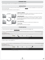
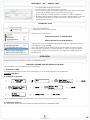
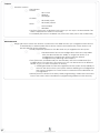
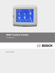
MAIN MENU AND WINDOWS MENU
figure 1
At the top you can distinguish the two main sections in which the SW is divided: 'Main' and
'Windows' (figure 1). By activating the 'Main' tab a menu pops up, with icons that allows
logical browsing, activating the 'Windows' tab pops up a menu that allows the activation
of disabled windows.
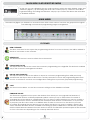
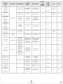
MAIN MENU
The Main bar (figure 2) is divided into several sections within which various functions are grouped into logical
units allowing customer and programming pages management.
figure 2
CUSTOMER
NEW CUSTOMER
The 'New Customer' button opens the programming window for a new customer, that will be added to
the list of customers on the software.
REFRESH LIST
The 'Refresh list' button is used to refresh the customers list.
EXPORT DATA TO FILE
The 'Export data to file' button saves the customer's programming on a single file. This button is enabled
only in the customer's management window.
IMPORT DATA FROM FILE
The 'Import data from file' button allows to import a customer's programming from a file previously
created with the 'Export data to file' button. Use this procedure to move the programming data from
one PC to another or create a new configuration starting from a previously prepared programming.
SAVE
The 'Save' button allows to save the customer's settings on the database software.
FIRMWARE UPDATE
The 'Firmware Upgrade' button opens the window from which you can upgrade the firmware of
the connected devices or KS-BUS peripherals (which can be put up to date without the need of
changing the system wirings or configuration). First you have to select whether you want to update a
device connected to the PC and listed in the 'Serial ports and devices connected' list, or if you want
to prepare your file to be saved on a USB flash drive in order to connect it to the device you want
to update. By pressing the next button you can select the device you want to update, where is also
shown the latest firmware revision available. Performing updates to basis the PC will also be updated
with the latest firmware released for each device in the list. The firmware update requires a few seconds
to from a few minutes depending on the currently selected device
4
lares
programming manual
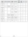
DEVICE DATA
ADD
The 'Add' button creates a new item in the active window, in example if we are in the 'Phonebook'
page, by pressing this button we will be able to add a new number in the phone book. If we are in the
'Zone' page we can add a new zone, and so on. It can be used in place of the buttons in 'Palette'.
DELETE
The 'Delete' button clears the item selected in the active window; in example if we are in the
'Phonebook' page by clicking this button the selected contact will be deleted. If we are in the 'Zone'
page we will remove the selected, and so on.
REFRESH
Use this button to refresh the current view of the active window.
TEMPLATES
This button allows to toggle from the simplified programming to the total one and vice versa.
COMMUNICATION
LOAD ALL
SEND ALL
The 'Load all' and 'Send all' buttons uploads/sends all programming to devices.
These two buttons are also available in the 'Navigator' window.
LOAD PAGE
The 'Load page' and 'Send page' buttons loads/sends the entire displayed page
to the device (example Phonebook).
SEND PAGE
LOAD
The 'Load' and 'Send' buttons loads/sends only the selected item to the device
(example a Phonebook number).
SEND
lares
programming manual
5
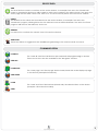
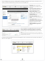
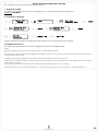
WINDOWS MENU
The 'Windows' bar (figure 3) contains buttons allowing the user to enable the main windows of the software. To
activate a window just click with your mouse on the corresponding button.
figure 3
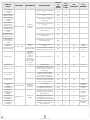
WINDOWS
CUSTOMER LIST
The 'Customer list' window allows control of customers and allows the database management. Using
this window you can create, edit, delete and manage customers by clicking with the right mouse
button on the customer name. Double clicking on the customer name will open the programming
overview, called 'Customer manager'.
DETAILS
This window shows the programming details of the selected event.
PLUGPLAY
This window shows the devices connected to the PC and detected by the platform. Displays the
communication port (serial port), the connected device, the customer code associated with the database,
the description that allows us to identify different products and firmware Version of the device.
WELCOME
In this window are presented the main functions of the software and the latest news in the Ksenia world.
UTILITIES
PALETTE
The 'Palette' offers the major common components of the current device. Simply drag the desired item
in the main window to insert it into the programming data.
OUTPUT
Debug trace window (generally not of interest to the user but only for SW maintenance).
PROPERTIES
Debug trace window (generally not of interest to the user but only for SW maintenance).
NAVIGATOR
The 'Navigator' allows you to navigate quickly through the various programming screens of the currently
selected device. The navigation buttons are only displayed when a device has been selected, in all
other cases, the window is blank and shows a 'No available view' message, because no device is
selected. When active, just double click on an item to access the relevant page. To send (upload) all
programming to the lares or other connected devices use the button 'Send all' ('Load all')
DOCUMENTATION
The button opens the folder on your computer in which the manuals have been copied during
installation of SW.
6
lares
programming manual
SUPPORT
OPTIONS
The 'Options' window enables you to manage the advanced options of the software:
inside the 'communications' tab you can disable automatic detection of devices connected to the
PC ('enable PlugPlay') or modify the parameters of communication speed. These parameters can be
modified if thereare issues communicating with the device.
Inside the 'vocal synthetizer' tab you can select the default text-to-speech engine in automatic
generation of voice messages. basis includes a free text-to-speech engine. Loquendo TTS2 entries will be
also displayed if a Loquendo USB key is connected to the PC.
CHECK FOR UPDATES
The 'Check for updates' button enables to check if there are any software updates. Performing
updates requires that the PC is connected to Internet3. Simply follow the instructions shown on the
screen to keep basis constantly up to date.
PLUGINS
The 'Plugins' folder contains settings for managing basis software modules and update management:
the 'Available Plugins' tab shows the available and not installed software modules.In order to install a
new module, select it and press the "install" button. In the 'Installed' tab you can manage your currently
installed modules, checking the status, features and eventually disable it. The settings menu shows a link
to the software update Center (you should not edit this parameter), and you can change the update
checking settings.
INFORMATIONS
The 'Information' button opens a window with the version of SW and SW related additional information.
2 LOQUENDO TTS it is a LOQUENDO S.p.A trademark. More information about Loquendo TTS functionality is available in the manual on the USB flash key containing the license for use of the
product
3
Specifically, it requires that your PC will be able to reach the site www.kseniasecurity.com also indirectly through access to a LAN.
lares
programming manual
7
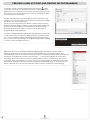
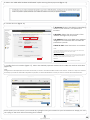
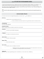
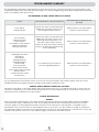
CREATING A NEW ACCOUNT AND STARTING THE PROGRAMMING
To create a new customer, simply press the button
'New
customer' and insert the appropriate data in relative window
(figure 4). Once created, the customer record is inserted in the
list, and you can optionally edit the data by pressing the right
mouse button on the name.
figure 4
Double clicking opens the 'Manage account' window; in this
window you can associate to the client the devices that will be
installed in the system (figure 5).
Once you have selected your device, simply press the 'Next'
button and then assign a name to the device itself, which will
identify and upload data conveniently in subsequent links.
By pressing the button 'Finish' it creates the device with its
programming menu (figure 6).
To open a programming page simply double-click on the entry
of the menu that you want to open (partitions, arming modes,
etc.). The 'Navigator' will be automatically activated to allow
you to move on several pages of programming without having
to return to the 'manage account'.
figure 5
figure 6
lares series have a very similar programming between the various models, here is
expressly indicated when some features are referable only to certain models. The
software allows you to create the zones (or outputs), determine where they phisically are
located (e.g. mainboard zones, keypad zones, ...), and then program the 'Scenarios'.
Scenarios are a set of actions that the panel performs when a particular event occurs,
as a zone alarm (or partition). For each event you can program a maximum of 8 output
activations, maximum 8 power outputs, maximum 8 switching outputs, activate up to 2
timers, activate the voice Communicator, SMS or email, or perform system arming.
8
lares
programming manual
DESCRIPTION OF PROGRAMMING PAGES
The Window bar (figure 3) contains buttons that allow you to enable the main Windows of the software. To
activate a window just click with your mouse on the corresponding button. We'll explore the available windows
in detail.
HARDWARE
PARTITIONS
On this page you can set the parameters for the partitions in the system. To add a new partition just press the
'Add' button. Let's see in detail each programmable field.
LABEL
The label is the name associated with the partition. This is used as a partition identifier in the programming
pages, as a string by mail or SMS dialer and automatic generation of voice messages. Moreover, this label is
displayed in the event log (logger).
AUTOMATIC MEMORY RESET
By selecting this option, when you disarm the partition any alarm memory will be automatically removed.
DELAYS SECTION
ENTRY
Time (in seconds) before the panel generates an alarm when violating a delayed input zone enabled on this
partition.
In order to maintain compliance with the norms listed on page 73 maximum input time should not exceed 45 sec.
EXIT
Output time (in seconds) during which the zones programmed as delayed in output even if violated will not
generate any alarm.
WARNING
Time (in minutes) before the system is armed according to the scheduler, during which the imminent arming is
reported by beeps on keypads.
In order to maintain compliance with the norms listed on page 73 this option should remain selected
PATROL
Time (in minutes) starting from a disarm of the system with patrol attribute with a code (key). When this time
expires the partitions will be automatically armed back.
NEGLIGENCY
Time (in hours) starting from partition disarming. If the partition is not armed when the time expires, it generates
the 'Partition Negligence' event that can be associated with actions (e.g. could be programmed to 24h to
manage any error or arming omission and thus allow the panel to automatically arm)
CYCLE
Time (in minutes) that determines the maximum duration of the alarm cycle. During the alarm condition, lares
does not generates further alarms in partition, and eventually generates an alarm event for each zone in
partition. This avoids the queue of numerous phone calls or reports.
lares
programming manual
9
LINKED EVENTS SECTION
This section provides a list of events related to the selected partition. Selecting one or more events you can
program the actions from the 'Details' window. The planned actions will be executed upon the occurrence of
the event. Refer to the paragraph 'Scenarios' for programming details.
ARMING MODES
In this page it is possible to program the arming modes, associable to the events in the 'Scenarios' page or to
numeric keys of the ergo LCD keypad or volo reader. Just press the
'Add' button to insert a new arming
mode.
Depending on the system model, up to 64 different arm methods can be defined.
In case of zones in alarm, arming the system will be possible only excluding these zones. The arming will not, under any circumstances,
be possible in case of tamper/fault events.
MODE
Is the description that you want to give to the arming mode, used as a label in the other pages and displayed
on the ergo keypad when the mode is active.
To add a new arming mode just press the button
'Add'.
Default basic programming already includes three predefined modes: total arming of all partitions, total
disarming and night mode (partial arming).
For each arming mode you can define the state each partition will be put in when the mode is enabled. To
change a mode programm, simply move in the mode/partitions grid up to the cell that you want to edit, and
click the left mouse button to get the desired programming. If you want to modify the programming of all
partitions for a particular arming mode just click the button to the left of the description. The 5 possible States
are:
NO ACTION
When the mode is enabled, the partition status is not changed.
ARM WITHOUT DELAYS
When the mode is enabled, the partition in armed and both of imput and output delays are reset.
ARM WITH DELAYS
When the mode is enabled, the partition is armed but input and output delays are valid (for the delayed zones
of partition only).
DISARM
When the mode is enabled, the partition is disarmed.
TOGGLE
When at least one partition is armed it disarms all partitions. When all partitions are disarmed, inserts them all.
10
lares
programming manual
ZONES
On this page you can program the parameters relating to the Zones. To program a zone, press on the
'Add' button or drag the corresponding icon from the 'Palette' programming page. Let's see in detail each
programmable field.
ZONE TYPE
Identifies the type of zone you want to use. Can be configured in the following ways:
WIRED
Wired zone
WIRELESS UNUM
Zone assigned to the unum wls indoor motion detector
POLI / NANUS MAGNETIC CONTACT
Zone assigned to the poli or nanus wireless magnetic contact
AUXILIARY ZONE ON POLI
Auxiliary zone assigned to the poli wireless magnetic contact
WIRELESS NEBULA
Zone assigned to the nebula wireless smoke detector
PROCESSING MODE
Select the zone type, which determines the type of signal analysis. Available in standard, roller blind, inertial
(for glass break sensors), command (if you do not want to use the area to generate alarms but only to enable
scenarios) or analog (to connect sensors with analog output 0-10V).
NOTE
1. To test the operation of the shutter-type and inertial sensors, taking into consideration the rapidity of the pulses generated by the
sensors themselves, we recommend that you test the system, instead of using the 'real time'.
2. To program a command zone, associate it to the partition that will arm/disarm, then associate the arming mode to the 'real-time of
zone' corresponding event in the 'Scenario' page.
3. Analogic zones may be attached only to Terminal 1 of auxi expansion modules. Analogic zones do not generate alarms or tamper,
but events associated with the input voltage level.
In order to maintain compliance with the norms listed on page 73 the 'Command' and 'Analogic' options should not be selected.
ARM MODE ON ACTIVATION
If you selected the processing mode 'command' you can use this menu to select the arm mode to execute at
the moment of the zone violation.
In order to maintain compliance with the norms listed on page 73 cannot be selected no insertion mode.
ARM MODE ON RESTORAL
If you selected the processing mode 'command' you can use this menu to select the arm mode to execute
when the zone comes back in stand-by.
In order to maintain compliance with the norms listed on page 73 cannot be selected no insertion mode.
lares
programming manual
11
LABEL
The label is the name that is associated with the zone. This is used as the identifier in the programming pages, as
a string by mail or SMS dialer and automatic generation of voice messages. Moreover, this label is displayed in
the event log (logger).
BALANCE
The choices are 'Normally Open', 'Normally Closed', 'Balanced (10K)', 'Double balance - Parallel (2 x 10K)',
'Double balance - series (2 x 10K)', 'Triple balance (3 x 10K)', 'Tamper single balance (10K)', 'Fault single balance
(10K)' and 'Custom'.
Selecting the last option, you can customize the thresholds and the bands.
Please refer to the panel manual for details on wiring and thresholds. In the case of analogic zones you cannot
select the type of balance, but there are 4 programmable thresholds that determine 5 levels. Depending on
the value of the input voltage the event corresponding to the level to which it belongs is generated.
In order to maintain compliance with the norms listed on page 73 ‘NC’ and ‘NO’ options must be excluded.
PARTITIONS MASK
Assign the zone at least at one partition, the association makes it possible to arm/disarm a zone (when the
associated partition is armed/disarmed), assign delay times to a zone. If a zone belongs to multiple partitions, it
raises the alarm only if all partitions to which it belongs are armed.
BYPASS MODE
BYPASSABLE
When this option is selected, the user will be able to bypass the zone. A bypassed zone does not report alarms.
Tampers and faults/masks will continue to be reported.
UNBYPASSABLE
If this option is selected the user will not be able to bypass the zone.
AUTO-BYPASSABLE
If this option is selected, the zone is automatically bypasses if it is violated when arming. The auto-bypass does
not exclude tamper and masks. The zone is automatically un-bypassed on next disarm.
In order to maintain compliance with the norms listed on page 73 this option must be used only with the scheduler.
AUTO-UNBYPASS
If this option is selected, the zone is automatically bypassed if violated when arming. As soon as it comes back
to stand-by it is automatically un-bypassed.
In order to maintain compliance with the norms listed on page 73 this option must be used only with the scheduler.
12
lares
programming manual
ATTRIBUTES
CHIME
If this option is selected, when the zone is violated with disarmed partitions, it generates beeps for 5 seconds on
all the keypads enabled on the same partitions.
ALWAYS ACTIVE
If this option is selected, when the zone is violated, an alarm will be generated regardless of the arming of the
partitions associated with the zone.
TEST
If this option is selected, the zone will only generate events in the log without generating any alarm.
PIR ALWAYS ACTIVE
Only on 'wireless unum' zones
If this option is not selected, the sensor detects any movement only when the system is armed, activating this
option the analysis performed by the sensor detection is always active. Option to use in case you want to use
the unum wireless sensor in home automation applications. After arming there might be a maximum delay of
30 seconds before the sensor is fully operational.
STANDARD INTENSITY OF THE SIGNAL
Only on 'wireless unum' zones
Normal Immunity
HIGH INTENSITY OF THE SIGNAL
Only on 'wireless unum' zones
If this option is selected it introduces an higher immunity threshold in the detection analysis.
lares
programming manual
13
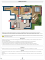
ENTRY/EXIT LOGIC
picture 7
Figure shows an hypothetical situation of entry into a dwelling at which the control panel of the system is
accessible only after intercepting some zones. Specifically the volumetric sensor marked with 0 must be the first
to be violated to not raise an alarm, then followed by the number 1 and number 2 in this exact order.
Warning: the above also applies if the zones belong to different partitions provided that you have programmed at least one arming
mode which arms them all.
ENTRY DELAY
Select this option if you want that violating that zone starts the entry delay (or if this is already started, will not
generates the alarm).
You can establish a path of entry on multiple levels, programming the input level parameter.
For example, with armed partitions, planning three levels has the following behavior:
•When entry delay in active you can break only one-level zones above the last zone violated.
• When entry delay in NOT active you can break only level 0 zones; the first violation starts the delay.
EXIT DELAY
Select this option if you want the zone not to generate alarms when the exit delay time is active.
LAST EXIT
Is the last zone on exit path, when it is violated and then restored during the exit delay time, it automatically
resets it.
Referring to Pic. 7, zones marked with 0, 1 and 2 must be marked as 'exit delay' and the 0 one marked as 'last
exit'.
14
lares
programming manual
NUMBER OF PULSES
Number of pulses required before the zone alarm is raised, this is standard pulses in case of 'Standard' or
'Command' zone, fast pulses in case of 'Shutter' or 'Inertial' zone. In the case of "wireless unum' zone, this value
can take only values 1-2 or 3-4 and will act on the detection sensitivity of the sensor.
PULSE LENGTH
Single alarm pulse duration. This value determines the amount of time that the zone must be violated before
a valid pulse is generated, and valid for all processing modes. For example, if we program a zone as 'Shutter',
the alarm will be generated if there are a number of fast pulses programmed (movement of the shutter) or
if the contact remains open for the programmed time in this window (security wire cutting). In the case of
programmed zone as 'Shutter' by setting this to 0 will make only quick analysis of impulses, and not generate
alarm if the contact remains open.
ALARM WINDOW
Window within which the number of programmed impulses must occur. In the case of "wireless unum' zone, this
attribute indicates the minimum time interval between the detection of two consecutive alarms. Increasing this
interval of time it is possible to increase the battery life of the sensor.
ALARM CYCLES
Number of alarm cycles that can be generated by the zone. Alarm cycles are reset at each zone arming.
INACTIVITY
If the zone is never violated for the programmed time (in minutes) the zone masking event will be generated
(passive control of masking).
PERIPHERAL AND TERMINAL
This section displays the device associated to the zone and the terminal where the sensor must be physically
connected.
LINKED EVENTS
This section provides a list of events related to the selected zone. By selecting one or more events is possible to
program the actions from the 'details' window. The planned actions will be executed upon the occurrence of
the event. Refer to the 'Scenarios' paragraph for programming details.
lares
programming manual
15
AND ZONES
On this page you can program the structure of AND zones. Putting zones in AND among them means that
alarm will be generated only if all parts that belong to the structure are violated. To add a zone in AND
structure press the
'Add' button or drag the corresponding icon from the 'Palette' in programming page.
For each structure there can be programmed two zones ('First zone' and 'Second zone') or three (also using the
'Third zone' field).
TIME WINDOW
Time, in seconds, during which the violation must occur for the two (or three) planned zones in the structure so
that they actually raise the alarm.
MAJORITY
This option is valid only if you have programmed in three zones, selecting, it is sufficient that two out of three
zones are violated in order to raise the alarm.
SEQUENTIAL
If this option is selected, zones must be violated in an exact sequence in order to generate the alarm (first,
second and possibly third zone)
OUTPUTS
On this page you can program the parameters relating to outputs. To program an output press the
'Add' button or drag the corresponding icon from the 'Palette' to the programming page. Let's see in detail
each programmable field. Aside from the 1A relay with double Exchange, all outputs are Open Collector
(transistorized) 500 mA
LABEL
The label is the description that you want to give to the output, will be used as identifier in other programming
pages.
MODE
MONOSTABLE
Is an output that turns on for a programmed time (ON time) upon the occurrence of the event and then
automatically return in stand-by.
BISTABLE
Is an output that follows the status of the corresponding event or can be triggered by an event and disabled
by another.
POLARITY
NORMALLY OPEN
Select this option if you want the output in stand-by mode when it's open and closes electrically grounded
when it's closed (negative to give).
NORMALLY CLOSED
Select this option if you want the output in stand-by mode when it's electrically closed to ground and active
when it opens (negative to send)
16
lares
programming manual
ANALOG
Select this option if you want the output to generate a voltage between 0 and 10V (maximum current of
20mA) when enabled. The voltage is 0V when output is in stand-by. Program the output voltage with the cursor
in the section 'Analog Value'.
NOTE
The analogue outputs can be mapped only to terminal 5 of auxi expansion modules.
TIMES
ON TIME
Time, in seconds, for which an output programmed as MONOSTABLE remains active in the occurrence of an
event.
CYCLE TIME
Is the sum of ON time plus a minimum time for which you want to keep the output off.
REMOTE CONTROL
Select this option if you want to control the output manually.
CONTROLLED
This option is valid only for the relay output. If enabled the Terminal +A needs the end of line resistor. The end-ofline resistor must have a value of 10KΩ. In case of tampering the event 'Controlled output tamper' is generated.
PERIPHERAL AND TERMINAL
This section displays the device associated to the output and terminal on which the output must be physically
connected.
EVENTS MANAGEMENT
Events acting on the output status are listed in 'Activated by', 'Deactivated by' and 'Toggled by' boxes. To add
a new event in one of these boxes, simply drag it from the 'Details' window. To delete an event from a box,
double click the event you want to delete. By pressing the button 'Clear events' you can clear all events that
act on the output.
The association of outputs to events can also be made from the 'Scenarios' page (see following paragraphs).
lares
programming manual
17
PERIPHERALS
On this page you can define system hardware configuration, add peripherals, their attributes and assign the
input output terminals functionalities. A physical terminal can be assigned to a zone (earlier defined), or to an
OC output, or left unused4.
MOTHERBOARD
The first part of the programming tree is the Motherboard terminals configuration. Let's see its programmable
parameters.
ZONES
i1..i6 TERMINALS
Inputs only
Program logic zones to be assigned to the terminals named i1...i6 on the motherboard.
M1..M4 TERMINALS
Inputs/Outputs
Program logic zones or outputsto be assigned to the terminals named M1...M4 on the motherboard5.�
VIRTUAL KEYPAD
The virtual keyboard is used during remote operations (e.g. via telephone or web-server).
MACRO FUNCTIONS
DESCRIPTION
Enter a description that you want to give to the scenario associated with the key, which will be used as a label
in the other pages, shown in the events log, used as the SMS Dialer strings and used in the generation of voice
messages.
ARM REQUEST
You can bind to the desired arming mode. Select Enabled if you want to activate the corresponding button.
The rest of operations (ouputs activations, timers, etc) must be programmed in the 'Scenarios ' page (see
following paragraphs)
PARTITION MASK
The Partition Mask can also be programmed for the Virtual Keypad, it defines the partitions on which the virtual
keypad will operate.
4 Basically
5 If
18
in our system we could have more physical zones (intended as terminals) than logical areas (which in the case of lares 128-IP are 128) as there may be unused physical areas.
a terminal is assigned to a zone, obviously cannot be assigned output function.
lares
programming manual
BUS PERIPHERALS
gemino GSM COMMUNICATOR
A gemino BUS Communicator can be added to the system. To add a gemino, drag the corresponding icon from
the 'Palette' to the programming page or select it by pressing the
'Add' button in the main menu.
Let's see its programmable parameters.
LABEL
The label is the description that you want to give to the communicator and will be used as a label in other
programming pages, shown in the events log and used as a string for SMS or e-mail alerts. Each device on the
BUS (hence also the gemino GSM communicator) is identified by a serial number with 6 digits. If this number is
known we can add it in the 'Serial number' field. If this number is not known, you can check on 'Assign serial
number from keypad' and then, from the ergo installer menu, you can assign to this programming a serial
number of a device connected to the KS-BUS.
ENABLE SIM #2
Select this option if there are two SIM cards installed on gemino.
ENABLE EXTERNAL ANTENNA
Select this option if an external antenna is wired on gemino.
DISABLE INTERNAL ANTENNA
This option is meaningful only if you have selected 'Enable external antenna'. Select this option if you don't
want the device to use the internal antenna in case of GSM signal issues (for example, if you put gemino inside a
metal box)
VOCAL MENU
Enable activation of voice guided menu, in case the number of the SIM is called. Through this tool the user can
control the panel after entering a valid user code.
JAM DETECTION
Select this option if you want gemino signals any noise on RF carrier of GSM that prevent communication.
Network parameters, credit control and expiration can be programmed for each SIM CARD.
INGOING GPRS DATA PORT
This parameter is required only if gemino is programmed to remotely manage the system via GPRS.
For more information, please refer to the 'REMOTE ASSISTANCE' paragraph.
lares
programming manual
19
OUTGOING GPRS DATA PORT
This parameter is required only if gemino is programmed to remotely manage the system via GPRS.
For more information, please refer to the 'REMOTE ASSISTANCE' paragraph.
DYNAMIC DNS SETTINGS
In this section parameters for configuring a server that handles dynamic DNS are programmable. For more
information refer to the paragraph "DYNAMIC DNS".
SIM OPTIONS
By selecting one of the available SIM you can view the options regarding the SIM itself.
CREDIT CHECK
CHECK INTERVAL
Is the maximum time, in days, between two credit checks. The device however, checks, the credit after every
phone call and every 10 SMS sent.
CHECK THRESHOLD
Is the threshold (expressed in Euro or in local currency) below which gemino generates the warning of credit
deficiency and performs the switching of SIM (if there are two SIM).
GSM SERVICE PROVIDER
Select an operator from among those proposed to enable the credit check.
DESTINATION LIST
Select Phonebook numbers that will receive reports of residual credit and SIM expiry. To add an entry, press the
green button. Up to two recipients can be added.
EXPIRATION CHECK
SIM EXPIRY DATE
Insert the SIM expiry date.
PERIOD
Is the time, in days,in which the deadline is stretched at each SIM recharge. If set to zero, the SIM expiry check
is not performed.
GPRS OPTIONS
APN SETTINGS
Is the access point to the GPRS network (this parameter is provided by GSM/GPRS operator).
This parameter is required only if gemino is programmed to remotely manage the system via GPRS. For more
information, please refer to the 'REMOTE ASSISTANCE' paragraph.
20
lares
programming manual
ergo LCD KEYPAD
ergo LCD keypads can be programmed in the system. To add an ergo, drag the corresponding icon from the
'Palette' to the programming page or select it by pressing the
'Add' button in the main menu.
Let's see its programmable parameters.
LABEL
The label is the description that you want to give to the keypad and will be used as a label in other
programming pages, shown in the events log and used as a string for SMS or e-mail alerts. Each device on
the BUS (hence also the ergo LCD keypad) is identified by a serial number with 6 digits. If this number is known
we can add it in 'Serial number' field. If this number is not known, you can check on 'Assign serial number from
keypad' and then, from the ergo installer menu, you can assign to this programmation a serial number of a
device connected to the KS-BUS.
BACKLIGHT
In this section, you can adjust the level of backlighting of the keypad. Select the 'Eco' mode if you want the
keypad backlight disabled in stand-by.
VOLUME
In this section, you can adjust the volume level of keypad speaker.
M1..M2 TERMINALS
ZONE/OUTPUTS
Programming logical zones or outputs to be assigned to the terminals indicated on your keypad with the name
M1...M2. If a Terminal is assigned to a zone, it obviously cannot be assigned output function.
IDLE INFORMATION
Information displayed on the keyboard in idle state:
Date and Time: enables/disables the display of the date and time on the second line of the display.
GSM service: enables/disables the display of the operator and of the GSM signal on the second line of the
display (if a gemino GSM Communicator is configured on your system).
External temperature: enables/disables the display of the outdoor temperature on the second line of the
display (if at least one imago siren is configured on your system)
Internal temperature: enables/disables the display of the indoor temperature on the second line of the
display (if at least one radius siren is configured on your system)
Arming status: enables/disables the display of the arming status on the second line of the display. In addition,
enabling this option you can see the armed partition details by pressing '#' when the keyboard
is in idle state.
Violated zones: enables/disables the display that indicates whether the system is ready for arming on the
second line of the display. In addition, enabling this option you can see the detail of violated
zones by pressing ' ' when the keypad is in idle state.
Show warnings with PIN: If this option is selected the first row of the keypad does not show the system status
(SYSTEM OK, ALARM, TAMPER, etc.) until you enter a valid PIN.
In order to maintain compliance with the norms listed on page 73, the option 'Violated zones' and the option 'Arming starus' must be
disabled. In addition, the option 'Show warnings with PIN' must be enabled.
lares
programming manual
21
ACOUSTIC FEEDBACK
Select which acoustic alerts you want to enable. You can freely select the different options according to your
needs.
EXIT TIME
Select this option if you want to enable acoustic warning on the keypad during the exit time.
In order to maintain compliance with the norms listed on page 73, this option must be enabled.
PREALARM
Select this option if you want to enable acoustic warning on the keypad during the entry time.
In order to maintain compliance with the norms listed on page 73, this option must be enabled.
WARNING
Select this option if you want to enable acoustic warning on the keypad during the time of notice (arming with
scheduler).
In order to maintain compliance with the norms listed on page 73, this option must be enabled.
CHIME
Select this option if you want to enable acoustic warning on the keypad associated with chime attribute zones.
NEW SOUNDS
Select this option to set the short sounds (1 beep every 5 seconds) during the input and output time, rather than
the continuous beeps.
CAPSENSE SENSITIVITY
In this section you can set the sensitivity for detecting key touches.
MACRO FUNCTION
DESCRIPTION
Enter the description that you want to give to the scenario associated with the key, which will be used as a
label in the other pages, shown in the events log, and used as the SMS Dialer string.
ENABLED
You can bind a key to the desired arming mode. Select 'Enabled' if you want to activate the corresponding
button with PIN entry, select 'No PIN' if you want to enable the function without putting the PIN, but simply
pushing for three consecutive seconds the corresponding key on the keypad (macro function). The rest of the
parameters (outputs activations, timers, etc) have to be programmed in the 'Scenarios' page (see following
paragraphs).
DISABLE AUTOMATIC SCENARIO EXECUTION
When you digit a PIN, the keypad runs the shown scenario after 3 seconds, if you do not press any key. Select
this option if you don't want the automatic execution.
22
lares
programming manual
PARTITION MASK
Assign the partitions on which the keypad can operate.
auxi EXPANSION MODULES
auxi expansion modules can be added to the system. The number of programmable expansion modules
depends on the Panel model. To add an expansion module, drag the corresponding icon from the palette to
the page or select it by pressing the
'Add' button in the main menu.
Let's see its programmable parameters.
LABEL
The label is the description that you want to give to the expansion module and will be used as a label in other
programming pages, shown in the events log and used as a string for SMS or e-mail alerts. Each device on the
BUS (hence also the auxi expansion modules) is identified by a serial number with 6 digits. If this number is known
we can add it in 'Serial number' field. If this number is not known, you can check on 'Assign serial number from
keypad' and then, from the ergo installer menu, you can assign to this programmation a serial number of a
device connected to the KS-BUS.
M1..M5 TERMINALS
ZONES/OUTPUTS
Programming logical zones or outputs to be assigned to the auxi terminals indicated with the name M1..M5. If a
Terminal is assigned to a zone, obviously it cannot be assigned output function.
pontis PSTN COMMUNICATOR
A pontis PSTN Communicator can be added to the system. To add a Communicator, drag the corresponding
icon from the palette to the page or select it by pressing the
'Add' button in the main menu.
Let's see its programmable parameters.
LABEL
The label is the description that you want to give to the communicator and will be used as a label in other
programming pages, shown in the events log and used as a string SMS or e-mail alerts. Each device on the
BUS (hence also the pontis PSTN Communicator) is identified by a serial number with 6 digits. If this number is
known we can it in 'Serial number' field. If this number is not known, you can check on 'Assign serial number
from keypad' and then, from the ergo installer menu, you can assign to this programmation a serial number of a
device connected to the KS-BUS.
RINGS
Program the number of rings that the Communicator must be held to answer incoming calls (if vocal menu is
enabled)
BYPASS ANSWERING MACHINE
By selecting this option the device will answer to phone calls only if a ring is detected, and then stopped.
Allows you to interact with the panel if it is installed on the same line as other devices that answer to calls
automatically (e.g., fax).
lares
programming manual
23
DISABLE TONE CHECK
Selecting this option will override the controls that the device makes before initiating an outbound call. This
allows you to interact with the panel if there were other devices that use the phone line (e.g. exchanger).
VOCAL MENU
Enables the activation of vocal guided menu by calling the telephone number associated with the pontis.
Through this tool the user can control the panel after entering a valid user code.
DO NOT CALL ON PSTN FAULT
If this option is selected, if the pontis detects the phone line failure phone calls will not be executed and the
event 'Communication Failed' will be generated.
imago OUTDOOR SIREN
imago outdoor sirens can be added to the system. The number of programmable sirens depends on Panel
model. To add a siren, drag the corresponding icon from the palette to the page or select it by pressing the
'Add' button in the main menu.
Let's see its programmable parameters.
LABEL
The label is the description that you want to give to the siren and will be used as a label in other programming
pages, shown in the events log and used as a string for SMS or e-mail alerts. Each device on the BUS (hence
also the imago outdoor siren) is identified by a serial number with 6 digits. If this number is known we can insert
it in 'Serial number' field. If this number is not known, you can check on 'Assign serial number from keypad'
and then, from the ergo installer menu, you can assign to this programmation a serial number of a device
connected to the KS-BUS.
OUTPUTS
BUZZER AND LAMP
The siren is handled by the system as an output. To activate both light and acoustic signaling we will assign an
output in the 'Buzzer and Lamp' window. When this output is activated (such as when an alarm event raises)
the siren starts sounding and flashing.
ONLY LAMP - ADDITIONAL LEDS
Outputs can also be assigned to the blinker only (Only Lamp) and auxiliary signalling LEDs (Additional Leds).
These can be programmed, for example, to report the arming status.
MAXIMUM ALARM TIME
Maximum time of activation of acoustic signal and siren light for cutting wires.
DUAL-TONE BUZZER
If this option is selected, the acoustic signal is performed by means of a sound with two separate frequencies, if
unchecked it instead sweeps the frequency.
24
lares
programming manual
BUS CONTROL
If this option is selected, the siren will emit an acoustic signal if there is no communication with the Panel for
longer than 10 sec.
TEMPERATURE
THRESHOLD CHECK
The siren integrates a temperature sensor, which allows to measure the outside temperature. By enabling this
option you can raise an event if the measured temperature is lower than the 'Low temperature threshold', an
event if the temperature is above the 'High temperature threshold' and an event if the temperature is between
the two thresholds.
DISABLE TEMPERATURE SENSOR
If this option is selected, the siren does not send the temperature and is not used for displaying outdoor
temperature on keypad (this is useful if there are two sirens, and one of these is installed in a sunny position,
distorting the outdoor temperature measurement).
radius INDOOR SIREN
radius indoor sirens can be added to the system. The number of programmable sirens depends on Panel model.
To add a siren, drag the corresponding icon from the palette to the page or select it by pressing the
'Add'
button in the main menu.
Let's see its programmable parameters.
LABEL
The label is the description that you want to give to the siren and will be used as a label in other programming
pages, shown in the events log and used as a string by SMS or e-mail alerts. Each device on the BUS (hence
also the radius indoor siren) is identified by a serial number with 6 digits. If this number is known we can insert it in
'Serial number' field. If this number is not known, you can check on 'Assign serial number from keypad' and then,
from the ergo installer menu, you can assign to this programmation a serial number of a device connected to
the KS-BUS.
OUTPUTS
BUZZER AND LAMP
The siren is handled by the system as an output. To activate both light and acoustic signaling we will assign an
output in the 'Buzzer and Lamp' window. When this output is activated (such as when an alarm event is fired)
the siren starts sounding and flashing.
ONLY LAMP
Outputs can also be assigned to the blinker only (Only Lamp).
MAXIMUM ALARM TIME
Maximum time of activation of acoustic signal and siren light for cutting wires.
USE EMERGENCY LAMP
If this option is selected, when power failure occurs, the siren turns on the power LED, lighting up a medium
sized room. Caution, you must install the lithium battery on the siren to allow operation as emergency light.
lares
programming manual
25
LED ALWAYS ON
If this option is selected, activating the associated output in 'Only Lamp' section, the LED is lit (not blinking).
TEMPERATURE
THRESHOLD CHECK
The siren integrates a temperature sensor, which allows to measure the outside temperature. By enabling this
option you can raise an event if the measured temperature is lower than the 'Low temperature threshold', an
event if the temperature is above the 'High temperature threshold' and an event if the temperature is between
the two thresholds.
DISABLE TEMPERATURE SENSOR
If this option is selected, the siren does not send the temperature and is not used for displaying outdoor
temperature on keypad (this is useful if there are two sirens, and one of these is installed in a sunny position,
distorting the outdoor temperature measurement).
PARTITION MASK
Programs the partitions associated with radius siren. When the system is asking to activate the alarm signalling,
the siren will activate the acoustic signal only if all partitions that are associated with the siren are armed. This
lets not to have the siren sound if people are in the house. If you want the siren to sound independently by the
arming mode, do not associate any partition to the siren.
volo PROXIMITY READER
volo proximity readers can be added to the system. The number of programmable readers depends on Panel
model. To add a reader, drag the corresponding icon from the palette to the page or select it by pressing the
'Add' button in the main menu.
We see its programmable parameters.
LABEL
The label is the description that you want to give to the reader and will be used as a label in other
programming pages, shown in the events log and used as a string for SMS or e-mail alerts. Each device on the
BUS (hence also the volo proximity reader) is identified by a serial number with 6 digits. If this number is known
we can insert it in 'Serial number' field. If this number is not known, you can check on 'Assign serial number from
keypad' and then, from the ergo installer menu, you can assign to this programmation a serial number of a
device connected to the KS-BUS.
IDLE INFORMATIONS
GREEN LED ON
If this option is selected, the green LED will turn on to confirm the system disarm. Otherwise, if you do not select
this option the reader will activate the red LED only to confirm the system arming, allowing also for colorblind
users to check the system status (LED on/system armed - LED off/ system disarmed).
LED TIMEOUT
Time, in seconds, during which the LED is activated to confirm an operation correctly performed.
26
lares
programming manual
TAMPER SENSITIVITY
In this section, you can adjust the sensitivity level of tamper accelerometer.
ARMING MODES AND LED
In this section, you can assign a specific configuration (Arming/Disarming/Scenario) to each available color.
The LED of the selected color will be activated to confirm the configured operation.
PARTITION MASK
Assign the partition on which the reader can operate.
divide BUS ISOLATOR / REPEATER
A divide BUS isolator/repeater can be added to the system. The number of programmable divide depends on
Panel model. To add a BUS isolator/repeater, drag the corresponding icon from the palette to the page or
select it by pressing the
'Add' button in the main menu.
Let's see its programmable parameters.
LABEL
The label is the description that you want to give to the BUS isolator/repeater and will be used as a label in
other programming pages, shown in the events log and used as a string for SMS or e-mail alerts. Each device
on the BUS (hence also the divide BUS Isolator/Repeater) is identified by a serial number with 6 digits. If this
number is known we can insert it in 'Serial number' field. If this number is not known, you can check on 'Assign
serial number from keypad' and then, from the ergo installer menu, you can assign to this programmation a
serial number of a device connected to the KS-BUS.
opis SUPERVISED POWER SUPPLY STATION
opis Supervised Power Supply Stations can be added to the system. The number of programmable stations
depends on Panel model. To add a supervised power supply station, drag the corresponding icon from the
palette to the page or select it by pressing the
'Add' button in the main menu.
Let's see its programmable parameters.
LABEL
The label is the description that you want to give to the Supervised Power Supply Station and will be used as
a label in other programming pages, shown in the events log and used as a string for SMS or e-mail alerts.
Each device on the BUS (hence also the opis Supervised Power Supply Station) is identified by a serial number
with 6 digits. If this number is known we can insert it in 'Serial number' field. If this number is not known, you can
check on 'Assign serial number from keypad' and then, from the ergo installer menu, you can assign to this
programmation a serial number of a device connected to the KS-BUS.
lares
programming manual
27
duo BUS WIRELESS TRANSCEIVER
duo BUS wireless transceivers can be added to the system. The number of programmable transceivers depends
on Panel model. To add a wireless transceiver, drag the corresponding icon from the palette to the page or
select it by pressing the
'Add' button in the main menu.
Let's see its programmable parameters.
LABEL
The label is the description that you want to give to the Wireless Transceiver and will be used as a label in other
programming pages, shown in the events log and used as a string for SMS or e-mail alerts. Each device on the
BUS (hence also the duo BUS Wireless Transceiver) is identified by a serial number with 6 digits. If this number
is known we can insert it in 'Serial number' field. If this number is not known, you can check on 'Assign serial
number from keypad' and then, from the ergo installer menu, you can assign to this programmation a serial
number of a device connected to the KS-BUS.
ENROLL WIRELESS DEVICES
Wireless devices enrolling occurs in three steps. Pressing the 'Enroll Wireless Devices' button in 'Peripherals'
section it will start a Wizard designed to facilitate this operation.
1. ENROLLING / PROGRAMMING OF duo TRANSCEIVERS (BUS)
1. If you do not have the serial number of the duo transceivers (BUS) press 'assign serial' in 'peripherals realtime'
section.
2. Proceed in the device programming as specified in the appropriate sections.
2. ENROLLING / PROGRAMMING OF duo REPEATERS
1. If you do not have the serial of duo repeaters, put on sabotage the selected device for a few seconds and
then put it back in service. Do this for all repeaters.
2. Proceed in the device programming as specified in the appropriate sections.
3. ENROLLING / PROGRAMMING OF WIRELESS DEVICES
1. Enrolling of wireless devices:
• The Contacts and the Detectors are enrolled on the tamper restore.
• The Remote Controls are enrolled on the long press of the info button.
• Smoke sensors are captured as soon as powered them up or pressing the button on the radio module.
2. Proceed in the device programming as specified in the appropriate sections.
28
lares
programming manual
WIRELESS PERIPHERALS
duo REPEATER
One or two duo wireless repeater can be added to the system. To add a wireless repeater, drag the
corresponding icon from the palette to the customer manager page or select it by pressing the
'Add'
button in the main menu.
After choosing wireless tab, duo wireless repeater and OK buttons, the programming page will open.
LABEL
In the label field you must write the identifier name for the duo repeater. It will be used as a call sign in other
programming pages, shown in the event log (logger) and used as a string by SMS or e-mail alerts. Each device
in the system (hence also the duo Wireless Repeater) is identified by a serial number with 6 digits. You can insert
it in 'Serial number' field or you can check the 'Assign serial number from keypad' box and then, from the ergo
installer menu, you can assign automatically the serial number to the device.
poli / nanus MAGNETIC CONTACT
Up to 64 poli / nanus wireless magnetic contacts can be added to the system. To add a wireless magnetic
contact, drag the corresponding icon from the palette to the customer manager page or select it by pressing
the
'Add' button in the main menu.
After choosing wireless tab, poli magnetic contact and OK buttons, the programming page will open.
LABEL
In the label field you must write the identifier name for the wireless magnetic contact. It will be used as a call
sign in other programming pages, shown in the event log (logger) and used as a string by SMS or e-mail alerts.
Each device in the system (hence also the poli / nanus Magnetic Contact) is identified by a serial number with 6
digits. You can insert it in 'Serial number' field or you can check the 'Assign serial number from keypad' box and
then, from the ergo installer menu, you can assign automatically the serial number to the device.
MAGNETIC CONTACT
Input here the Logic Zone previously programmed, to be associated with magnetic contact.
AUXILIARY CONTACT
Input here, if desired, the Logical Zones previously programmed, to associate to auxiliary contacts. Auxiliary
zones are not available on nanus Micro Magnetic Contact so this section should not be programmed.
SUPERVISION INTERVAL
Maximum amount of time that elapses between two transmissions. If the panel does not receive any data over
an interval of twice the supervision interval, it will raise a 'missing peripheral' event.
lares
programming manual
29
unum INDOOR MOTION DETECTOR
Up to 64 unum wireless motion detectors can be added to the system. To add a motion detector contact, drag
the corresponding icon from the palette to the customer manager page or select it by pressing the
'Add'
button in the main menu.
After choosing wireless tab, unum indoor motion detector and OK buttons, the programming page will open.
LABEL
In the label field you must write the identifier name for the motion detector. It will be used as a call sign in other
programming pages, shown in the event log (logger) and used as a string by SMS or e-mail alerts. Each device
in the system (hence also the unum Magnetic Contact) is identified by a serial number with 6 digits. You can
insert it in 'Serial number' field or you can check the 'Assign serial number from keypad' box and then, from the
ergo installer menu, you can assign automatically the serial number to the device.
ASSIGNED ZONE
Logic Zone previously programmed, to be associated with the detector.
OVERSEEING INTERVAL
Maximum amount of time that elapses between two transmissions. If the panel does not receive any data over
an interval of twice that of overseeing, raises a 'missing peripheral' event.
nebula SMOKE DETECTOR
Up to 64 nebula wireless smoke detectors can be added to the system. To add a motion detector contact, drag
the corresponding icon from the palette to the customer manager page or select it by pressing the
'Add'
button in the main menu.
After choosing wireless tab, nebula smoke detector and OK buttons, the programming page will open.
LABEL
The label is the description that you want to give to the smoke detector and will be used as a call sign in other
programming pages, shown in the event log (logger) and used as a string by SMS or e-mail alerts. Each wireless
device (hence also the nebula smoke detector) is identified by a serial number with 6 digits. If this number
is known we can insert it in 'Serial number' field. If this number is not known, you can check on 'Assign serial
number from keypad' and then, from the ergo installer menu, you can assign to this programmation a serial
number of a wireless device.
ASSIGNED ZONE
Logic Zone previously programmed, to be associated with the detector.
OVERSEEING INTERVAL
Maximum amount of time that elapses between two transmissions. If the panel does not receive any data over
an interval of twice that of overseeing, raises a 'missing peripheral' event.
30
lares
programming manual
opera REMOTE CONTROL
Up to 64 opera wireless remote controls can be added to the system. To add a remote control, drag the
corresponding icon from the palette to the customer manager page or select it by pressing the
'Add'
button in the main menu.
After choosing wireless tab, opera remote control and OK buttons, the programming page will open.
LABEL
The label is the description that you want to give to the remote control and will be used as a call sign in
other programming pages, shown in the event log (logger) and used as a string by SMS or e-mail alerts. Each
wireless device (hence also the opera remote control) is identified by a serial number with 6 digits. If this number
is known we can insert it in 'Serial number' field. If this number is not known, you can check on 'Assign serial
number from keypad' and then, from the ergo installer menu, you can assign to this programmation a serial
number of a wireless device.
VIBRAMOTOR
Activates the vibration as confirmation of executed command.
CONFIGURING FUNCTION KEYS
You can configure up to 7 different actions, associated to the keys of wireless remote control. In addition to
associate a possible arming previously programmed, you can program the function keys (outputs activation,
SMS sending, mails, ...) from the 'Scenarios' page (see following paragraphs).
PARTITION MASK
Assign the partition on which the remote control can operate.
31
lares
programming manual
LOGIC
PHONEBOOK
You can enter up to 100 contacts6 to whom can be sent reports. To add a contact/IP receiver to the
phonebook press the
'Add' button, or drag the corrisponding icon from the Palette. Before inserting data,
will be asked if you want to add a phone contact or a IP receiver.
NEW CONTACT
NAME
The name associated with the phonebook position.
NUMBER
Phone number (optional). If this field is not programmed, the phonebook position cannot receive SMS or voice
calls.
NOTE
Insert the international prefix (e.g. 0039) could affect the proper functioning of the device.
E-MAIL
E-mail address (optional). If this field is not programmed the contact position cannot receive emails.
OPTIONS
CANNOT RECEIVE SMS
Select this option if you don't want the number to be alerted via SMS (for example if it is a landline phone
number).
CANNOT RECEIVE VOCAL MESSAGES
Select this option if you don't want the number to receive voice calls.
ENABLE CALLER ID
If this option is selected, the device, in case of incoming calls from this number, raises the corresponding event
of 'recognised-caller' but the incoming call is rejected7.
SEND CONTACT-ID
When this option is selected, the alerts are sent through the Contact-ID Protocol.
PRIORITY ON GSM / PSTN
For each number you can program which communication channel must be used first (priority on GSM or on
PSTN). Non-priority channel is automatically used as the reserve.
CONTACT-ID
To send the Contact-ID you need to enter the customer code of 4 digits (usually provided by the Central
Monitoring Station). All event codes are preprogrammed.
CUSTOMER CODE
Program the 4 digit customer code for use in the transmission of Contact-ID.
.
6 The
maximum number of configurable contacts depends on the model of the lares
7 This
function is particularly useful if you want the simple call coming from a given number can activate a policy (panel arming, closure of a relay, ...) at no cost.
lares
programming manual
32
NEW IP RECEIVER
RECEIVER DESCRIPTION
Name associated with the receiver.
RECEIVER ID NUMBER
SIAIP DC09 Receiver identifier, 6 hexadecimal digits maximum.
TRANSPORT ID
SIAIP DC09 identifier for the Panel used with the current receiver, 12 hexadecimal digits maximum.
IP ADDRESS
IP address of Receiver.
PORT
Remote port on which the receiver listens.
PROTOCOL
Application protocol used to format the data field of the transport protocol SIAIP DC09 (Contact-ID, SiaLevel3..)
APPLICATION ID
Panel application protocol identifier (Contact-ID, SiaLevel3) used with the current receiver.
OPTIONS
SIAIP DC09 protocol options.
AUTOMATIC BACKUP
Communication to this receiver, in case of failure, is repeated toward the backup receiver.
PRIORITY ON BACKUP RECEIVER
The communication is sent FIRST to the backup receiver, and repeated, in case of failure, to this receiver.
PRIORITY ON GPRS
When selected, this option sets the priority of the channel GPRS communication instead of the ethernet
channel.
USE TIMESTAMP
When selected, this option sets the date and time information on the data package.
TRANSMIT OVER TCP
Sets the use of TCP instead of UDP for sending alerts.
33
lares
programming manual
BACKUP
Backup receiver of the current one.
BACKUP RECEIVER
BACKUP PERIOD (S)
Time, in seconds, on which you send notifications to the backup receiver since the main receiver is off.
EVENTS MANAGEMENT
List of events that will be reported to the current receiver. To add a new event to this box simply drag it from the
'Details' windows. To delete an event from this box, double click on the event you want to delete. Pressing the
'Clear events' button will delete all events in this box. Pressing the 'Default' button, a predefined set of events
will be added to this box.
The events listed in this box can be also programmed in the 'Scenarios' page (see following paragraphs).
USER GROUPS
On this page you can schedule the activation mode of the user groups (codes and/or keys), associated to the
scheduler. There are 4 distinct user groups, activated and deactivated in 16 different programmable mode.
MODE
Description of the user group activation mode, editable with a double click on the desired box. In each mode
you can define 3 different states for each user group:
NO ACTION
When the mode is enabled, the group status is not changed.
ENABLED
When the mode is enabled, the group is active and codes/keys are valid.
DISABLED
When the mode is enabled, the unit is off and the codes/keys are not valid.
Any unused groups can be left in the 'No Action' mode. Default basic programming already includes two
predefined modes: activating and deactivating of all groups.
NOTE
If you use a PIN code or a key belonging to a disabled group, the system generates the reporting of incorrect PIN.
lares
programming manual
34
CODES
In this page user codes can be added. Please, note that here you will just add a new user code, but not
the PIN. The PIN will be changed from the keypad. To add a code, press the
'Add' button, or drag the
corresponding icon from the Palette.
Using the codes you can restrict operations on the system. There are 3 levels of access:
1. Access by any person (without entering any code).
2. Access by user (entering user codes).
3. Access by the maintainer (entering installer code).
Only 1 installer code is available in the system.
All codes are 6 digits, for a total of 1.000.000 combinations
LABEL
The label is the name associated with the code. This is used as the identifier in the code pages, as a string from
the SMS or email dialer and for automatic generation of voice messages. Moreover, this label is displayed in the
event log (logger).
GROUP
Choose, if desired, the group associated with the code. If you don't select any groups your code will always be
active, otherwise it will be active only when the associated group is active.
PARTITION MASK
Assign the partition on which the code can run.
ENABLED
If this option is selected, the code is active.
MASTER
A master code can also handle the advanced menu on LCD keypad, as well as modify PIN codes and
qualifications that are not master too and that have the same partition mask.
PATROL
If this option is selected, the code will make disarming operations, but the partition will automatically be
rearmed at the end of the patrol time programmed in the 'Partitions' page.
ARM ONLY
If this option is selected, the code will not perform disarming.
35
lares
programming manual
NO ACTION
If this option is selected, when the code is typed on the keypad is only activated the scenario that corresponds
to the 'Recognized Code' event, without allowing to activate the scenarios associated with the keypad or
enter the menu. This option is very useful if you want to use code to do one action only (example output
activation to open a door).
LOAD PINs
By pressing this button you can load PIN from the Panel, and save them on the software database. This action,
in conjunction with the 'SEND PINs', button, will allow you to clear or replace the panel without loosing the PINs.
Please, note that PINs are NOT SAVED to the basis database by default, so please, NEVER use the 'SEND PINs'
key without using the 'LOAD PINs' before.
TAGS
In this page you can add your Tags8 to be used on ergo LCD keypads or on volo proximity readers. Here the tags
are just enabled, theirs acquisition will then be performed by keypad programming menu. To add a Tag, press
the
'Add' button, or drag the corresponding icon from the Palette. All Tags have a 4 byte code, for a total
of 4.294.967.296 combinations.
LABEL
The label is the name associated with the Tag. This is used as the Tags identifier on programming pages, as a
string by mail or SMS dialer and automatic generation of voice messages. Moreover, this label is displayed in
the event log (logger).
GROUP
Choose the group associated with the Tag. If you don't select any groups the Tag is always on, otherwise it will
be active only when the associated group is active.
CHANGE PARTITION MASK
Assign the partition on which the Tag can operate.
INSTALLER
It is a Tag that allows access to the Installer menu using a code valid for a limited period of time by an hour9.
ENABLED
If this option is selected, the Tag is active.
PATROL
If this option is selected, the Tag can make disarming operations, but the partition will automatically be
rearmed at the end of the time of patrol programmed in the 'Partitions' page (see following paragraphs).
8 The
Tags are RFiD devices available on request.
9 The code will appear on the keypad display as soon as you approached the Tags set as a Installer Tag. This feature is particularly useful in the case of a large contractor with personnel
to their dependencies; at the end of the working relationship with a particular person is simply the withdrawal of key supplied to the person himself, without the need to brush up on all
facilities for editing 'Installer' codes of access to systems.
lares
programming manual
36
ARM ONLY
If this option is selected, the Tag will not perform disarming.
NO ACTION
If this option is selected, when the key is approached to the volo reader is only activated the scenario that
corresponds to the event 'Recognized Code', without allowing to activate the scenarios associated with the
reader or enter the menu (if approached to the ergo keypad). This option is very useful if you want to use code
to do one action anly (example output activation to open a door).
LOAD IDs - SEND IDs
By pressing this button you can load IDs from the Panel, and save them on the software database. This action,
in conjunction with the 'SEND IDs', button, will allow you to clear or replace the panel without loosing the IDs.
Please, note that IDs are NOT SAVED to the basis database by default, so please, NEVER use the 'SEND IDs' key
without using the 'LOAD IDs' before.
VOICE MESSAGES
In this page you can create, record, listen and delete your voice messages. To add a new voice message,
press the
'Add' button or drag the corresponding icon from the Palette. Next, you have to select the way to
create the message, importing the list from a .wav file format, or by registering them using the voice tab of your
PC or, finally, generating them using the TTS engine (text-to-speech). In this case it is sufficient to write the text in
the window and the software will automatically generate the corresponding voice message, or generate them
from descriptions (labels) inserted into various pages.
GENERATE MESSAGES FOR THE VOCAL GUIDE
By pressing this button you can automatically generate all voice messages for the system.
37
lares
programming manual
GRAPHIC MAPS
figure 8
In this page you can customize
the Panel web-server by inserting
maps, placing buttons or icons on
the maps themselves, to put links to
other web-servers, such as that of
IP cameras. For more details (figure
8) please refer to the FAQ section
of the website www.kseniasecurity.
com.
NOTE
After a Panel firmware update you might
need to resend graphic maps using the
'Send Page' button.
SECTION
lares Integrated web-server can interface
directly cameras that support the ONVIF
standard, enabling real-time viewing of
streaming video from camera directly onto the
Web-Server.
The ONVIF (Open Network Video Interface
Forum) is a global forum which purpose is
facilitating the development and use of a
global standard for interfacing security systems
based on IP, or create a standard where IP
devices that integrate surveillance functions
can communicate each other. ONVIF is an
organization founded in 2008 by an agreement
between Axis Communications, Bosch Security
Systems and Sony.
For more informations please visit:
www.onvif.org
SYSTEM REQUIREMENTS
Today ONVIF standard defines more or less forty commands.
To be sure that the camera is compatible with the Ksenia web-server, it must support at least the following:
ONVIF Core Specifications
ONVIF Media Service Specifications
• WS - Probe
• WS - Hello
• GetCapabilities
• GetDeviceInformations
• GetNetworkInterfaces
• GetProfiles
• GetSnapShotUri
Check with the manufacturer that the camera supports the above commands.
lares
programming manual
38
WEBSERVER CONFIGURATION
Web Server configuration requires that camera and the running basis PC are in the same subnet.. Here below
are described the operations sequence:
1.Connect the ONVIF camera and the PC runnig basis software to the same subnet.
2.Open the basis software, create or open an account and select the 'Floor Plants' page.
3.Select the map where you want to place the camera symbol, press the
'Add' button in the main menu.
4.Select 'Create a new symbol' and then 'ONVIF Camera'.
5.By pressing 'Search ONVIF devices' button you can scan the network to detect ONVIF connected cameras;
after scan a list of detected cameras will be shown.
6. Select the camera, fill in the fields relating to the addresses as needed, and press the 'Finish' button.
NOTE
Some camera models often require enabling ONVIF Protocol, verify in the manual supplied by the manufacturer any activation procedure.
NETWORK TOPOLOGY AND ONVIF LIMITATIONS
ONVIF Protocol is normally used to allow devices with heterogeneous uses to communicate each other. Most
commands provides for the interchange of information via UDP and HTTP POST packets.
ONVIF command structure was created to be compatible with Web Services and SOAP packaging standards
(XML over HTTP). This peculiar structure allows devices to communicate each other, but needs a good
preparation of the network in order to function at its best.
After setting the graphic maps, basis will retrieve all the information it needs from the camera, to allow the webserver to communicate with the device.
For this reason it is necessary, at creation of your web-server and graphic maps, that the ONVIF camera and
the PC running basis are connected in the same subnet, and it is also necessary that the communication ports
to the ONVIF standard are open.
The following table summarizes the requirements for a proper recognition of the ONVIF devices.
39
NETWORK
CONNECTIONS
The PC on which basis is running and the ONVIF camera must be connected in
the same subnet. They must be physically connected to the same router and they
must have the same subnet mask (Subnet Mask).
COMMUNICATION
PROTOCOL
In communication-time basis and ONVIF device will use UDP port 3702 (standard
Web Services) and port 80 over HTTP.
Both ports must be open and not blocked by firewall.
lares
programming manual
DATA ACCESS MODALITY
Accessing data of ONVIF cameras depends on device manufacturer.
None of the ONVIF commands that are implemented to achieve the standard integration in basis need
authentication. They can be used without the use of camera username and password.
Any authentication request is entrusted to the device when accessing video streaming.
It is possible, however, that some producers force the ONVIF to require authentication for commands that do
not require specifically. For this reason, the basis programming interface provides the possibility of providing
authentication data directly during scanning devices.
Hence there are two possible scenarios:
1. A scan is made for ONVIF devices that are on the network without provide authentication data (leaving
blank its charts controls);
In this case the chart of ONVIF detected devices will display all compatible cameras that do not require
authentication.
2. A scan is done by providing user name and password in the appropriate fields. In this case the chart of
ONVIF detected devices will display all compatible cameras that comply with the authentication criteria
entered and all cameras that do not require authentication.
ETHERNET
For expert users
This page is only available for lares16-IP, lares 48-IP and lares 128-IP. It contains the network configuration
parameters10.
Default values for lares are: 192.168.2.90 static IP address, netmask 255.255.0.0, default gateway 192.168.2.1
BOARD NAME
NETBIOS name
Is the name by which you can identify your board on the network, factory setted as 'lares_board'. This feature is
available only on Windows networks.
ENABLE DHCP
By enabling this option, the board will automatically configure the network parameters only if a DHCP server is
present in the network.
SMTP
The checkbox 'Enable SMTP' will enable the panel to send emails using the SMTP protocol.
E-MAIL FROM
Input here the sender name (eg. Alarm System). Some servers may require the insertion of a valid email address
(e.g., servers that do not require authentication).
SERVER
Set the name of SMTP server (e.g. mail.provider.net).
Set the name used to access on SMTP server.
Set the authentication password.
USER NAME
PASSWORD
10 We
recommend that you contact your network administrator for setting these parameters before connecting the panel on the network, in order to avoid conflicts and malfunctions,
even on other apparatuses.
lares
programming manual
40
ENABLE SSL
Select this option if the mail server requires encryption (e.g. gmail). In this case you must set also the SMTP port
(eg. 465).
ENABLE WEBSERVER
This option enables the integrated web-server
ENABLE HTTPS
In case you want to use an encrypted communication, simply select this option. In this case, the address will
be: https://<panel name>:<HTTPS port>
LIMIT NUMBER OF SIMULTANEOUS ACCESSES
Selecting this option is limited to 5 the number of IP addresses that can access the WEB resource.
WEBSERVER
USER NAME
Set the username for the web-server login.
Default: admin
PASSWORD
Default: lares
Set the password for web-server login authentication.
PORT
Default: 80
In this section it is possible to program the communication port.
HTTPS PORT
Default: 443
This section is available only if you select the option 'Enable HTTPS'. Allows the use of encrypted communication.
ENABLE PING
By selecting this option, your board will respond to ping requests coming from the network.
ENABLE UDP DISCOVERY POLICY
By selecting this option, the panel automatically appears in the devices list, but only if the PC is on the same
subnet. Otherwise, you will need to set the IP address manually to communicate with the panel. In case of PC
and Panel are in two different subnets you will need to access the 'Remote Assistance' section (see following
paragraphs).
ENABLE DYNDNS
By selecting this option you can enable a server to handle dynamic DNS.
41
lares
programming manual
DYNAMIC DNS
By selecting this option you can enable the dynamic DNS function.
INTRODUCTION
The most known server which provides dynamic DNS service is dyn.com so here we will refer to it, but any other
server can be used.
The dynamic DNS operation is shown in Figure 9.
figure 9
•DETECT IP CHANGE
Make a check on your address, by request to the appropriate server.
If your address has changed, please update IP.
•PERFORM UPDATE
Send an update is to make a connection to a server that provides a
dynamic DNS service and report your change of address. To do this
you must have registered at that site and you create a hostname to
bind this address.
•PROCESS RETURN
Do a check on the response obtained by the DDNS server.
•NOTIFY USER
Report the user situation if required.
CONFIGURATION
1. Open the browser, go right at www.dyn.com and go to the DNS section (figure 10).
figure 10
2. Select “Sign In” option (figure 11)
figure 11
lares
programming manual
42
3. If you already have an account, simply login by entering your Username and Password, otherwise you will
need to provide the required data to create a new account (figure 12).
figure 12
Username: Enter a user name
with which you can sign in to your
account.
Password/Confirm Password: Enter
and confirm the password with
which authenticate access.
Email/Confirm Email: Enter and
confirm a valid e-mail address.
Security Image: Enter the numbers
displayed in the box.
Subscribe Newsletter: Select or
clear this option depending on your
needs.
I accept the terms of..: Select this
option after you have read the
Acceptable Use Policy, the Service
Agreement and Privacy Policy.
Create Account: Press to confirm
and conclude the registration
process.
figure 13
Upon completion of the registration process the server will
send an email for confirmation and account activation
at the address previously posted (figure 13). Follow the
procedure given in the email and activate your account.
NOTE
The email sent from the server contains a link to access to complete your
account activation. This procedure must be performed within 48 hours from
placing their data on the server.
4. Once you have activated your account and logged in, return to the DNS section and select the 'Add Host
Services' option (figure 14)
figure 14
43
lares
programming manual
5. Select the 'ADD NEW DYNDNS HOSTNAME' option among those proposed (figure 15).
figure 15
6. Create the host (figure 16)
1. Hostname: Enter in this field the identifying
name of your network, your panel or its
location.
figure 16
1
2. Dominio: Select the second part of the
address among those proposed.
2
3. IP Address: Enter in this field the IP address
assigned to the network that contains the
panel from your ISP.
3
4. Add To Cart: Press the button to continue.
NOTES
1. The address through which the user can access to the network that
contains the panel, and then to the panel, will be:
http://hostname.domain
2. For security reasons, if one http port other than the one set by default
(port 80) has been assigned to the panel, you must specify this value in
the address, preceded by the character 'colon'.
4
EXAMPLE:
http://hostname.domain:1234 in which 1234 is the port value.
7. Confirm the host creation (figure 17), select the desired payment method and confirm the service activation
(figure 18).
NOTE
The figure shows the displayed screen from the server if you want to activate the TRIAL version of the service, works for 15 days. It is however
necessary to provide the information required for payment, at which will reference in case you want to activate the standard service.
figure 17
figure 18
At this point you can access your network by typing the host just created on your browser bar or simply you can
do a ping to that host without knowing its IP address.
lares
programming manual
44
PROGRAMMING OF ACCOUNT DATA ON LARES PANEL
You can program your account data via basis software or simply via the web-server integrated in the Panel.
DNS SERVICE
Enter the DNS service name to which you are registered. Example: dynDNS.com
PORT
Specify the port number used by the IP Check service. Default: 80
HOST NAME
Enter here the host name defined in the preceding paragraphs.
Example: esempio.dynDNS-at-work.com
USER NAME
Enter here the user name defined in the preceding paragraphs. Example: kseniasecurity
PASSWORD
Enter here the password defined in the preceding paragraphs. Example: 123456
SERVER IP CHECK
Enter here the server name on which the Panel will check your IP..
Example: checkip.dyndns.com
PORT
Specify the port number to which refers the IP Check service. Default: 80
After programming these parameters the panel, at regular intervals (or in cases where ISP-assigned IP address
to its network were to change), will contact the server that provides the dynamic DNS service to update the IP
address. The dynDNS service is also supported by most routers. By adjusting the parameters for the DNS service
on your router you can achieve the same result.
45
lares
programming manual
ENABLE NTP CLIENT (NETWORK TIME PROTOCOL)
By selecting this option you can enable the date and time synchronization service from a NTP server.
NTP SETTINGS
NTP SERVER HOST NAME
Select a server among those proposed.
TIME ZONE OFFSET
Value (in hours) of time zone set.
SEND WEB SERVER
Enable the web-server function in the panel. You can choose:
EXTENDED: tabular format that allows a quick check-up of the system status and the remote management and
control of the system.
COMPACT: graphic format that allows you to control and remotely manage the system.
ADVANCED ETHERNET PARAMETERS
In this section, you can modify the programming ports, it is recommended that you contact your network
administrator for setting these parameters before connecting the Panel on the network, in order to avoid
conflicts and other equipment malfunctions.
IP EVENTS
Here you can program the panel to send communication through ethernet using the SIA DC-09 protocol.
ENABLE EVENTS OVER IP
Enables the panel to send periodic supervision messages to the IP receiver.
ENABLE CHANNEL SUPERVISION
Enables the panel to send periodic supervision messages to the IP receiver
SUPERVISION INTERVAL
Time (in seconds) programmed to configure the interval between two supervision packages.
ETHERNET SERVER PORT
Port on which the panel will receive data from central station. In the network it must be open in input.
ETHERNET CLIENT PORT
Port used from the panel to send data to the central station. It must be open in output. If central station uses
UDP, most likey this value is the same of server port.
lares
programming manual
46
GPRS SERVER PORT
Port on which the panel will receive data from central station on GPRS channel.
GPRS CLIENT PORT
Port used from the panel to send data to the central station on GPRS channel. It must be open in output. If
central station uses UDP, most likely this value is the same of GPRS server port.
SUPERVISED RECEIVER
Receiver to which the panel will send the supervision data.
OPTIONS
WARNING ENABLEMENT
Enable/disable of single failure sources. Disabling a failure source will permit normal panel operation even if the
failure is present. (Es. a IP panel with no ethernet connection should have Ethernet failure disabled)
In order to maintain conformity with norms listed on page 73 all faults must be enabled.
GENERAL OPTIONS
MAINS FAULT DELAY
Configure the delay time (in minutes) prior to raise the 'Power Supply fault' event.
ALLOW WAEK PINs
Selecting this option disables the robustness control of the pins, which Panel makes to prevent the insertion of
easily identifiable PINs (e.g. date of birth, etc..).
UNBYPASS ZONES AFTER DISARM
Selecting this option, manually excluded Zones are automatically re-included at the moment of disarming.
In order to maintain conformity with norms listed on page 73 this option must be enabled.
LOCK KEYPAD ON WRONG PIN
Selecting this option enables every keypad to lock after 3 wrong codes.
In order to maintain conformity with norms listed on page 73 this option must be enabled.
USE ZONE #1 FOR SERVICE/SYSTEM TEST
By selecting this option the zone 1 behaves as a service entrance, putting the Panel in maintenance when it is
violated.
47
lares
programming manual
CLEAR TAMPER MEMORY WITH USER CODE
By selecting this option you can use user code to erase the tamper memories from the 'Reset Alarms' menu on
the ergo keypad.
In order to maintain conformity with norms listed on page 73 this option must be disabled.
LIMIT LOG ENTRY NUMBER PER EVENT
Enabling this option keeps the memory in the register a maximum of 8 occurrences for each specific event,
occurred within a arming/disarming cycle or until the next maintenance of the system.
If this option is NOT selected the Panel will display the event log for each occurrence.
In order to maintain conformity with norms listed on page 73 this option must be enabled.
DENY SYSTEM ARM ON FAULT CONDITION
By default the Panel allows any kind of arming in the presence of a fault and/or tamper.
Selecting this option the Panel will not arms the partitions in case of faults.
In order to maintain conformity with norms listed on page 73 this option must be enabled.
DETECT BYPASSED ZONE TAMPER
If this option is not selected, disables both the alarm signals and sabotage of all excluded zones. By selecting
this option the zone exclusion only excludes alarms.
In order to maintain conformity with norms listed on page 73 this option must be enabled.
ENABLE FAULTS MEMORY
By selecting this option the Panel displays the keypad failure recovery through the words 'Fault Memory'. This
memory will be erased only after an inspection of the section 'Faults Status' by a level 2 user.
In order to maintain conformity with norms listed on page 73 this option must be enabled.
EN 50131 ARMING CHECK
By selecting this option the Panel aborts the arming if that generates an alarm and raises the 'Arming Fault'
event.
In order to maintain conformity with norms listed on page 73 this option must be enabled.
lares
programming manual
48
PERIODIC EVENT
The Panel can be programmed to periodically send an error report, for example, to check that it is working
properly.
DATE AND TIME FIRST PERIODIC TEST
In this section you can set the date and time of the first send a periodic message, in order to check it works
properly. periodic event.
PERIOD
Period (in munutes) of the periodic event. If this value is 0 periodic event will not be generated.
In order to maintain conformity with the norms listed on page 73 the maximum period allowed should not exceed 300 min.
VOICE DIALLER
CONFIRM REQUEST MESSAGE
Option to add a voice message at the end of all voice communication, in order to invite the listener to press
the key to confirm receipt of the message.
CONFIRM CALL RESULT
By selecting this option you will need to confirm the receipt of the call by pressing the button on the receiving
phone. Otherwise the device will accept the call as failed and proceed with the next number among those
configured. This option allows you to listen to the voice message without interrupting the sequence of calls. If
you enter the # key the panel will consider the call ackowledged. After pressing the # key you will enter the
voice driven menu to interact with the Panel (see User Manual).
In order to maintain conformity with norms listed on page 73 this option must be enabled.
CALL ALL NUMBERS
Selecting this option voice messages will be sent to all configured numbers. The sequence of calls will stop only
after all numbers in the list will acknowledge the call.
NOTE
The system considers equally valid possible answers from electronic devices (e.g., faxes and answering machines).
CONFIRM CALL ESIT AND CALL ALL NUMBERS
By combining these two options voice messages will be sent to all configured numbers. The sequence of calls
will stop only when all numbers listed will have confirmed the call esit by pressing the button.
HIDE CALL STATUS ON KEYPADS
This option will disable the keypads to show the calls status (i.e in case of duress disarm).
TRIES
Number of call attempts that the device performs on each configured number before the message is deleted
(also in case of non-receipt of confirmation).
REPETITIONS
Represents the number of voice message repetitions during the same call.
REMOTE ASSISTANCE SETTINGS
To program these options please refere to the 'Remote Assistance' paragraph.
49
lares
programming manual
INSTALLER DATA
Data that will be show on the ergo keypads pressing the Enter key in idle state.
DATE AND TIME
In this section you can set the date and time, using the
'Set' button.
Daylight saving will enable the automatic switching of summer/winter time. checking this option will show a
panel in which date/time changing can be programmed.
NOTE
To schedule the date and time you must enter a valid user PIN.
SCHEDULER
The scheluder is useful to arm/disarm the system using arming modes or on a partition basis. It can also be used
to enable/disable user groups (both codes and RFID keys).
For example, in the case of anti-intrusion system installed in an office, you might schedule the total insertion of
the System throughout the day on 25 December; for normal working days you could schedule the disarming
during work hours and automatic rearming in other times. Graphics mode is easy to guess: to add a daily
pattern, press the
'Add' button or drag the corresponding icon from the Palette.
GENERIC TIMERS
Every event in the system can activate or deativate up to 2 generic timers. Both the start and the expiration of
these generic timers are system events as well, so they can be used to generate cyclic events.
For each timer can be programmed a label and a duration expressed in seconds.
SCENARIOS
The scenarios page is the heart of the System. Each event in the system can be used to generate actions, as
output set/reset/toggle, generic timers start/stop, arming modes, calls. Hereafter some examples are shown.
EXAMPLE 1 - PROGRAMMING ARMING/DISARMING FROM KEYPAD
Let's assume that you have previously defined one or more keypads and activated some functions that can be
associated to keys.
Let's further say you have defined in the arming page an arming mode called 'Total Disarming 1' and one
called 'Total Night Arming'.
If you want to associate with the 0 Key on the keypad 1 a system disarming will be sufficient to assign the event
'0 Key on Keypad 1' in the 'Arming mode' column the 'Total Disarming 1' entry earlier defined. In the same way
we can associate with the 1 key in the same Keypad 'Total Night Arming' mode; we could assign to the "Disarm
partition 1" event the reset of an output.
EXAMPLE 2 - RELAY AND COMMUNICATOR ACTIVATION TO THE OCCURRENCE OF AN ALARM
When a partition alarm occurs, simply assign an output (e.g. relay) in the output column of the 'Partition
Alarm' event, if we also want to start a phone call or an SMS you should add in the recipients column the
programmed numbers in the phone book. In the case of voice messages you should also select the voice
messages attached to the corresponding event.
lares
programming manual
50
EXAMPLE 3 - ARMING WITH COMMAND ZONE
Let's further say you have defined in the Arming page an arming mode called 'Total Arming 2'. Suppose that
you want to use a zone to make a partition arming: simply associate with the 'Real Time Zone Alarm' the 'Total
Arming 2' mode.
In order to maintain conformity with norms listed on page 73 this option must be disabled.
DETAILS OF PROGRAMMING PARAMETERS
Programming status of events is summarized in a table that displays, the actions on outputs and timer, the
recipients notified and its associated voice message and arming mode enabled at the time of the occurrence
of each event. In this table events can be sorted by each column, just clicking on the header of the column
you want to use for sorting. Displayed columns can be customized by clicking with the right mouse key on the
headers ot the table. By enabling the 'Groups Event' option you can organize events for type. In addition, you
can display only one subset of events by filtering by name. This can be done by inserting a string on 'Filter:'. The
'Show Descriptions' option allows you to display labels for the programmend outputs, zones, contacts and so
on.
The actions programmed for each event can be modified from the 'Details' window, acting directly on the
table or by programming panel that can be enabled by checking the 'Event Detail' box. Thanks to multi-select
feature you can quickly change the attributes for a group of multiple events. Let's see the meaning of each
field.
OUTPUTS ON
Select the outputs (up to 8) that can be activated upon the occurrence of a specific event.
OUTPUTS OFF
Select the outputs (up to 8) that can be deactivated upon the occurrence of a specific event.
OUTPUTS TOGGLED
Select the outputs which can change status upon the occurrence of a specific event (i.e.: If the output is at
rest is activated, if it was activated returns to rest).
ACTIVATE OUTPUTS
This option allows to choose whether the programmed outputs must be always enabled, enabled only when
there is at least one partition armed or only when all the partitions are disarmed.
NOTE
To select the output function mode (activation, deactivation and toggle), press the icon to the right of the output name.
Every output can be used for any set of events. I.e. an output can be set if at least one partition is armed and reset only if ALL the partitions
are disarmed. Follow these steps:
• Set the output in all the "Armi partition..." columns
• Reset the output in all the "Disarm partition..." events
• Provide taht the output is programmed as bistable output and the "Remote control" check is de-activated .
This type of operation must occur under the following conditions:
• The output must be bistable type
• The output shouldn't have the 'Remote Control' option enabled
• The output shouldn't be handled as a toggle on no other scenario
• The output shouldn't be associated with spot-type events.
If one ot these condition is not true, the output will be activated for any of its programmed events, but be will deactivated for any of the
programmed events.
51
lares
programming manual
TIMERS
Select the timers (up to 2) to start/stop for the event. For each of them select the start (RED dot) or stop (GREEN
dot) clicking the button at right of selection.
DESTINATIONS
Select the destinations (up to 8) of messages to be sent from the panel. The kind of message depends on the
programmed attributes in the phonebook page. For example, if we associate to contact an email address,
upon the occurrence of the event will automatically be sent the email, and so on. In the case of reports with
SIA DC-09 Protocol select the IP receiver. The panel will manage automatically the backup receivers, so just put
one IP receviver here.
MESSAGES
For voice call, select the messages to send for the event in these 4 fileds.
Contact-ID and SIA event code
CODE
ARMING MODE
Select partition arming mode that should be activated from the event.
RESET MEMORY
Check this box if the event should clear the alarm memories.
CLEAR CALL QUEUE
Check this box if the event should clear the communication queue (i.e. for disarming events)
RESET ALARMS
Check this box if the event should reset the alarm outputs (i.e. relais for disarming events)
In order to maintain the GRADE 3 the Panel must be connected to the alarm receiving center exclusively through GPRS or ETHERNET
with SIA DC-09 communication protocol, using the gemino GSM dialler (ATS4)
In order to maintain the GRADE 2 the Panel must be connected to the alarm receiving center via text-to-speech communication using
the pontis PSTN board (ATS2). Each event must be associated with a transmission.
lares
programming manual
52
REMOTE ASSISTANCE
With all lares Panels you can make remote assistance via the gemino BUS Communicator, using the GSM/GPRS
network for data transmission (figure 19). In addition, for lares 16-IP, lares 48-IP and lares 128-IP it is possible to
perform remote support on Ethernet. To enable remote assistance on Ethernet simply check the 'Use Remote
Communication on Ethernet' option and enter the address in the provided space. Enabling remote assistance
on GPRS requires a greater number of steps that will be described below.
-
+P i5
i6
-
+
A
B
- 12V -
figure 19
+P1 M1 M2
- +P1 M3 M4
-
NC C NO +A +R
+P i1
i2
-
+P i3
i4
CENTRALE - CONTROL PANEL
CENTRALE - ZENTRALE
lares
GSM - GPRS
COMMUNICATOR
ISP
WEB
ETHERNET
PC
PHYSICAL LAYER
The communication over GPRS is made class 10, 3R2T asymmetrical multislot, that is 3 timeslot in receiving
(43200 bps max) and 2 timeslot in transmission (28800 bps upload).
The gemino BUS interfaces the lares Panel through KS-BUS.
FIRMWARE LAYER
Performing remote assistance on GPRS requires that the devices comply at least with the following constraints
on firmware:
DEVICE
FIRMWARE VERSION
BUILD FIRMWARE
gemino BUS
01.00.xx
552
lares (all models)
01.01.xx
657
To enable remote assistance, following parameters should be configured:11
‘OPTIONS’ PAGE
• Select the 'Enable Remote Assistance on GPRS' option.
• Set the value (in minutes) of the session timeout.
The session timeout indicates how long the Panel is accessible
remotely on GPRS channel. This timer is started immediately after user
enabling and rearmed for each start/service acceptance by the
installer.
11 Remote
53
assistance does not require any modem or additional device. It just requires an up-to-date basis software.
lares
programming manual
‘PERIPHERALS’ - ‘BUS’ - ‘GEMINO’ PAGE
• Set APN in SIM dedicated section
• Set the ports for the GPRS communication
• If you want to reach a Panel through a dynamic DNS service rather
than using IP (DDNS) select "Dynamic DNS Settings'
•Ensure that the network operator provides a public IP address
•Enabling the 'Enable DynDNS' check, fill the related fields to record
the "panel end-point on GPRS" at a server which provides the
dynamic DNS service.
‘SCENARIOS’ PAGE
•Group events by kind
• Open the 'Other Events' branch
There are two new events:
Remote Assistance on GPRS Enabled
Remote Assistance on GPRS Disabled
These events can be programmed and as such you can bind to them
SMS and/or e-mail sending.
Upon the 'Enabled' event the body of the message or email contains
the IP address obtained on GPRS channel. In case you log the device
on a DynDNS server it is not necessary to program the SMS except for
confirmation.
OPERATION
Remote Assistance operation consists of 5 logical blocks:
ENABLING/OPENING SUPPORT SESSION BY THE USER
This operation can be performed in several ways:
1. Activation by SMS:
The SMS body should contain: (user code)(M/m) 1, no spaces between text characters.
Example: 147258m1
2. Activation by Keypad:
Upon completion will display the Remote Assistance status in the first row of the display.
3. Enabling by Protocol
For third-party applications that want integrate themselves with lares Panels.
lares
programming manual
54
STARTS/ACCEPTANCE BY THE INSTALLER/ASSISTANT
1. Enter the 'Remote Assistance' page
• Select the 'Remote Communication on GPRS' option. Once selected you can
enter the logical name or IP address (received via mail or sms after programming)
and the listening port of Panel in Remote Assistance mode.
• As soon as the panel you just added in the previous step appears in the devices
table (in Plug&Play mode check on devices is automatically done), you can start a
Remote Assistance session.
• Press on the 'Start Remote Session' button to begin a session. Upon receipt of the
response message you will be able to interact with the Panel.
DATA EXCHANGE
Data exchange between lares and basis software will take place as per protocol, except for sending/receiving
information involving a delta of delay introduced by GPRS channel.
END OF ASSISTANCE SESSION BY THE INSTALLER/ASSISTANT
Pressing 'Stop Remote Session' in 'Remote Assistance' page you will terminate the current session.
NOTES
During a remote assistance session by the installer you can do more than one 'Send page', then more than a entry in programming. The
data configured during this session are actually updated on Panel only at the end of the current session. With this option you can also
modify the data configuration closely connected to Remote Assistance, without losing control of the GPRS Panel interface.
If the 'Remote Assistance by Installer' logoff message does not arrive at the Panel, all data successfully sent will be updated only after the
expiry of the time-out of 'Remote Assistance by User' session.
Installer Pin, although disabled during Remote Assistance, is automatically considered enabled.
55
lares
programming manual
END OF ASSISTANCE SESSION BY THE USER
This operation can be performed in several ways:
1. Activation by SMS:
The SMS body should contain: (user code)(M/m) 0, no spaces between text characters.
Example: 147258m0
2. Activation by Keypad:
Upon completion will display the Remote Assistance status in the first row of the display.
3. Disabling by Protocol
For third-party applications that want integrate themselves with lares Panels.
NOTES
Before starting the remote assistance, it would be better to make preliminary check:
Check that the communication ports from gemino and installer pc side are open (in the worst case both inbound and outbound), that is a
port mapping has been made.
Configure ports keeping in mind that communication with Ksenia peripherals uses the UDP protocol.
Verify that the IP addresses assigned to the SIM CARD are actually public IP addresses (sometimes, in case of prepaid SIM, see Vodafone,
public IP are not assigned).
Such verification must be completed even if pc installer side uses a wireless device for the connection.
Increase the timeout and communication attempts on the options page: timeout at least >= 8 seconds
lares
programming manual
attempts at least >= 3.
56
KEYPAD LANGUAGES
On this page system language can be choosen. You can program up to 10 languages on the Panel (available
languages on lares), taken from the list of available languages (available languages on basis).
DATE AND TIME OPTIONS
DATE MODEL
Select the date model you want among those proposed:
DD/MM/YY: day – month – year
example: 31/01/13
MM/DD/YY: month – day – year
example: 01/31/13
YY/MM/DD: year – month – day
example: 13/01/31
HOUR MODEL
Select the hour mode you want between 12h and 24h.
EVENTS LOG
On this page you can read the event log of the Panel. Press the
'Load' button in the main menu to read the
event log. You can select events and copy them (Ctrl-C), for example, to store them on a text document.
Events are stored on non-volatile memory (Flash) with 100.000 write cycles and a minimum of 10 years of data storage.
REALTIME EVENTS
Activating this button, the software periodically checks the Panel register, downloading the new events as they
occur.
REALTIME
In the Realtime pages you can check the System status. It provides the display of the Zones status (Realtime
zone), the outputs status, partition status (Realtime partition), the status of devices connected on the BUS
(Realtime devices), the wireless devices status (wireless Realtime) and Panel and failures status (Panel realtime).
57
lares
programming manual
ergo LCD KEYPAD PROGRAMMING MENU
To enter the programming menu by ergo keypad enter the installer PIN (default 123456) or use a RFID key with
installer attribute. Refer to the keypad manual for the use and functions of buttons and circular scroll.
This section shows the programming tree. About the meaning of the parameters, but specific descriptions, you
can simply reference the preceding paragraphs, since both the order of the menu and used terminology is the
same as that used on basis software.
NOTE
Log in as Installer is inhibited when partitions are armed. Also log in as Installer (both with key and code) must be enabled by a main user
in the user menu, under 'Install. Permission' setting to ON. If enable is set to OFF the use of the installer code is inhibited (considered wrong
code).
INSTALLER MENU STRINGS
To access a sub-menu in programming phase you have to tap
the ‘ENTER’ key.
Event Log
Verified events scroll starting from last one
Scroll in detail the informations (date, time, generator) about the selected event.
Programming
See following paragraph
Program from USB
Allows loading data from USB key connected to the Panel.
Language
Scroll among available languages
IP Address
IP Address of Panel (xxx.xxx.xxx.xxx)
Failure status
Scroll the faults in progress
Battery status
Devices batteries status
Zones status
Scroll the zones and display their status
Display the value of the resistance (in ohms) read in the selected zone. If the zone
is analogic the voltage appears at the zone input.
Modify PIN
(appears only if the programming menu is entered by a code, and not by a RFID key)
lares
programming manual
58
ergo version
It shows the serial number and the firmware version of ergo keypad
INSTALLER MENU STRINGS
Partitions
Scroll of partitions
• Description
• Automatic memories restore
• Pre-alarm time (sec.)
• Exit time (sec.)
• Notice time (min.)
• Patrol time (min.)
Arming
Scroll of arming
• Description
• display the actions associated with each partition for that arming mode.
'-' = no action
'0' = disarming
'1' = arming
'i' = immediate arming
'c' = toggle
• Scroll of partitions and possibility to associate the action to be performed when
that arming mode is relied. Possible actions for each partition are:
• No action
• Arming
• Immediate arming
• Disarming
• Toggle
59
lares
programming manual
Zones
Scroll of zones
• Kind of Zone
• Wired
• Wireless PIR
• Wireless CM
• Wireless AUX
• WIreless SMOKE
• Description
• Mode
• Not used
• Standard
• Inertial
• Roller blind
• Analogic (it appears only if the zone has been programmed analogic by basis. Using the keypad is not possible to program
an analogic zone)
• Balance
• Normally open
• Normally closed
• Balanced
• Double balance
• Triple balance
• Tamper balance
• Custom (it appears only if the thresholds have been customized
through basis. When programming from keypad is not possible thresholds customization)
• Partition Mask
• Scoll of partition and ability to associate or not the zone to the selected partition.
Zones
Scroll the Zones
• Chime
• 24 Hours
• Test
• Command
• Pulse number (only values ranging from 1 to 7 are valid)
• Noise Immunity (displayed only if the zone is 'Wireless PIR')
• PIR always active (displayed only if the zone is 'Wireless PIR')
• Input delay
• Immediate
• Delayed
• Output delay
• Immediate
• Delayed
lares
programming manual
60
Outputs
Scroll the outputs
• Description
• Mode
• Not used
• Digital
• Analogic
• Polarity
• Normally open
• Normally closed
• Kind
• Monostable
• Bistable
• ON Time (This menu is displayed only when you set output as Monostable. The
value is expressed in tenths of a second)
• Controlled (This menu is enabled only for the the relay one in the mainboard)
BUS Peripherals
Assign (this menu shows the devices connected to the lares and not yet configured. Each device
is identified by its serial number. Each device can be associated with a new device or a
device already set by software).
• Scroll peripherals present on the BUS and not yet registered in the system
• Scroll between the saved configurations that are compatible
with the selected device. Ability to assign the device to a
configuration or register the device with the default
configuration by selecting <New Periph.>
• Free (This menu is enabled only for the the relay one in the mainboard. The
configuration of the device is not removed, so it can be reused on a different
device, e.g. If you want to replace a device).
• Scrolling between the devices registered in the system and possibility to
remove the device from your System without deleting the configuration
that can be assigned to a new device connected on the BUS and not
yet registered.
• Delete (remove devices from lares panel programming.. Unlike the command
'Free' in this case is also cancelled the programming defined for this device).
61
lares
programming manual
ergo Keypads
Scroll the ergo keypads
• Partition Mask
• Scroll the partitions and ability to enable the keypad for the
selected partition
• Information at rest
• Date and time
• External temperature
• Internal temperature
• GSM Operator
• Partition status
• Zone status
• Keys and Scenarios
• Key 0 Description
• Key 0 with PIN
• Key 0 without PIN
• Key 1 Description
• Key 1 with PIN
• Key 1 without PIN
• Key 2 Description
• Key 2 with PIN
• Key 2 without PIN
• Key 3 Description
• Key 3 with PIN
• Key 3 without PIN
• Key 4 Description
• Key 4 with PIN
• Key 4 without PIN
• Key 5 Description
• Key 5 with PIN
• Key 5 without PIN
• Key 6 Description
• Key 6 with PIN
• Key 6 without PIN
• Key 7 Description
• Key 7 with PIN
• Key 7 without PIN
• Key 8 Description
• Key 8 with PIN
• Key 8 without PIN
• Key 9 Description
• Key 9 with PIN
• Key 9 without PIN
volo Proximity Readers
Scoll the volo
• Partition Mask
• Scroll the partitions and ability to enable the reader to the
selected partition
• LEDs and scenarios
• Green LED
• Red LED
• White LED
• Blue LED
• Yellow LED
• volo options
• LED at disarmed system
• Display of System status
lares
programming manual
62
Wireless
Enroll
• <New Periph.>
• Enrolling…
• <Custom programmation>
Free
• Disconnecting wireless devices from the lares panel, without loosing their
programming data
Delete
• Remove wireless devices from lares programming
Codes management
New code
• Scrolling between the empty positions on which you can save the new code
Code options
• Enter PIN
• Scroll the valid codes
• Description
• Change PIN
• Partition mask
• Scrolling between the different partitions and
ability to enable or disable the code for the
selected partition
• Enable
• Main code
• Patrol
• Arming only
Delete code
• Remove an existing code
63
lares
programming manual
Tags management
Save Tag
• Enroll a new RFID tag in the system
Assign Tag
• Assign a RFID tag to a previous programmed tag position
Tag options
Delete Tag
• Remove a previously programmed RFID tag
• Modify RFID tag parameters
Tag options
• Description
• Installer
• Enable
• Patrol
• Arming only
• Partition mask
• Enable/disable RFID tag on partitions
Scenarios
Arming mode
Output
• Assign arming mode at the current event
• Output
• Action
• Assign outputs to the current event
• No action
• Enable
• Restore
• Toggle
lares
programming manual
64
SUMMARY TABLE OF START-STOP EVENTS
events that have a specific start and end point*
*The table refers to the lares with 1.5.XXX firmware version
KIND OF
EVENT
CATEGORY
Zone alarm
Zone restore
Sabotaggio
Zona
Ripristino
Sabotaggio
Zona
Excluding zone
Including zone
Fault or zone
masking
Zone
Events
Fault restore or
Masking
Realtime zone
Restore of
realtime zone
Partition arming
Partition
disarming
Chime on
Partition
End of chime on
Partition
Patrol on
Partition
End of patrol on
Partition
Partition
pre-alarm
Restore Partition
pre-alarm
Partition notice
End of Partition
notice
Exit time
End of exit time
65
Partition
Events
RECURRENCE
OCCURS
WHEN...
ENDS WHEN...
Contact
ID
EVENT
CODE
Number of
Zones
An armed zone is
violated
The status
change or the
zone is disarmed
130
Number of
Zones
A zone is
sabotaged or
put in blackout
The status
change
137
Number of
Zones
The zone is
excluded
The zone is
reincluded
Number of
Zones
A zone is masked
or the inactivity
time expires
The status
change or the
zone is armed
Number of
Zones
A disarmed
zone is violated
or a violated
zone switch
from armed to
disarmed
The zone comes
back to rest
600
Number of
Partitions
The zone is
armed
The zone is
disarmed
400
Number of
Partitions
The chime is
enabled
The chime is
disabled
Number of
Partitions
Disarming System
with a code or
patrol Tag
End of patrol
period or System
rearming
Number of
Partitions
Input time starts
Input time expires
or is stopped by
disarming the
partition
Number of
Partitions
The notice of
scheduler is
started
The notice of
scheduler is
stopped
Number of
Partitions
The exit time is
started
The exit time
expired or is
stopped
lares
programming manual
SIA
EVENT
CODE
GG
CCC
BA
BR
TA
TR
570
BB
BU
BT
388
BR
Associated
Partition
00
if the zone
belongs
to more
than one
partition
Zone
number
UA
UH
CL
OP
Partition
number
000
KIND OF
EVENT
RECURRENCE
OCCURS
WHEN...
ENDS WHEN...
Contact
ID
EVENT
CODE
Number of BUS
Peripherals
A peripheral
disappears from
the BUS
The peripheral
comes back to
work properly
330
Number of BUS
Peripherals
The peripheral is
open
The peripheral is
closed again
341
Number
of Wireless
Peripherals
A wireless
peripheral
disappears
The wireless
peripheral
comes back to
work properly
Number
of Wireless
repeaters
The peripheral is
open
The peripheral is
closed again
341
Number of
generic timers
The Timer starts
The Timer expires
600
Altri
eventi
1
The Panel cover
is open
The Panel cover
is closed
Power supply
lares Panel
+ number of
duo wireless
receivers +
number of opis
power supply
stations
Missing power
supply on lares,
on duo wireless
receiver or
on opis power
supply station
Restore of power
supply on lares,
on duo wireless
receiver or on
opis power supply
station
lares Panel
+ number of
imago sirens
+ number of
radius sirens
+ number of
duo wireless
repeaters +
number of opis
power supply
stations
The battery
voltage drops
below the
threshold (when
missing net)
The 220V net
comes back
302
1
The Ethernet
cable is
disconnected
The Ethernet
cable is
connected
350
1
The pontis
telephone line is
cutted
The pontis
telephone line is
restored
351
1
Missing GSM net
on gemino
The GSM net on
gemino is restored
352
Enter the
programmation
with installer
code
Exit from
programmation
300
CATEGORY
Missing
Peripheral
Peripheral
restored
Peripherals
tamper
Tamper restore
Missing wireless
Peripheral
Peripherals
Restore of
wireless
Peripheral
Wireless
peripheral
tamper
Wireless
Peripheral
tamper restore
Start Timer
Stop Timer
Panel tamper
Panel tamper
restore
Missing net
Net restore
Timers
Low battery
Restore of low
battery
Power supply
Missing Ethernet
Ethernet restore
Missing PSTN
PSTN restore
Loss GSM net
Restore of GSM
net
Start
maintenance
Stop
maintenance
Other events
1
lares
programming manual
SIA
EVENT
CODE
ET
BR
ES
EJ
330
GG
CCC
Peripheral
number
00
Peripheral
number
00
Timer
number
000
00
000
00
000
00
000
00
000
00
000
00
000
00
000
ET
ER
ES
EJ
UX
UX
TA
137
TR
AT
301
AR
YT
YR
NT
NR
LT
LR
NT
NR
LB
LX
66
KIND OF
EVENT
CATEGORY
RECURRENCE
ENDS WHEN...
1
Removes a EOL
resistor on relay
Restore of EOL
resistor on relay
324
lares Panel +
number of opis
power supply
stations
The thermal
fuse enter in
protection
Restore of
thermal fuse
300
1
A remote
assistance
session via GPRS
is enabled
A remote
assistance
session via GPRS
is disabled
410
Failure of
IP receiver
supervision
The IP receiver
responds to
the supervision
packets
356
lares Panel +
number of opis
power supply
stations
The power
supply fails and
fails to provide
the necessary
current to the
system
The fault is
restored
300
lares Panel +
number of opis
power supply
stations
The output
voltage of
power supply
drops below the
threshold
The output
voltage of power
supply comes
back over the
threshold
312
Number of duo
transceiver
Radio noise
detected at
868MHz
End of radio
noise at 868MHz
137
Controlled
output tamper
Controlled
output tamper
restore
Fuse fault
Fuse restore
Other events
Power supply
GPRS Remote
Assistance
enabled
GPRS Remote
Assistance
disabled
Failed
supervision of IP
Receiver
1
Battery charger
fault
Power supply
Low output
voltage
Restore of low
output voltage
Radio noise on
transceiver
Restore of
radio noise on
transceiver
67
SIA
EVENT
CODE
GG
CCC
00
000
00
000
00
000
00
000
YA
YH
YI
YJ
RB
RS
Other events
Restore of
supervision of IP
receiver
Restore of
battery charger
Contact
ID
EVENT
CODE
OCCURS
WHEN...
Other events
lares
programming manual
YS
YK
YP
YQ
YP
YQ
XQ
XH
SUMMARY TABLE OF SPOT EVENTS
events that have a start only
NOTE
For Occurrence means the number of times the event occurs in the table. For example the alarm zone occurs once for each zone.
KIND OF
EVENT
CATEGORY
RECURRENCE
OCCURS WHEN...
First analogic
level
Analogic input voltage falls within
level 1
Second
analogic level
Analogic input voltage falls within
level 2
Third analogic
level
Fourth analogic
level
Zone events
Analogic levels
Number of
analogic zones
Contact
ID
EVENT
CODE
SIA
EVENT
CODE
GG
CCC
PARTITION ADDRESS
Associated
partition
Analogic input voltage falls within
level 3
00
if the zone
belongs to
more than
one partition
Analogic input voltage falls within
level 4
Numero
zona
Numero
zona
Numero
zona
Numero
zona
Fifth analogic
level
Analogic input voltage falls within
level 5
Partition alarm
The zone alarm occurs (one of
zones goes in alarm)
130
BA
Partition
number
000
The zone alarm occurs (one of
zones goes in tamper)
137
TA
Partition
number
000
The negligence timer expires
404
Partition
number
000
Missed arming
The partition arming is not
successful
0
UX
0 Key on
keypad X
Macro 0 activated on keypad or
code entered + macro 0
120
PA
00
000
1 Key on
keypad X
Macro 1 activated on keypad or
code entered + macro 1
120
PA
00
000
2 Key on
keypad X
Macro 2 activated on keypad or
code entered + macro 2
120
PA
00
000
3 Key on
keypad X
Macro 3 activated on keypad or
code entered + macro 3
120
PA
00
000
Macro 4 activated on keypad or
code entered + macro 4
120
PA
00
000
Macro 5 activated on keypad or
code entered + macro 5
120
PA
00
000
6 Key on
keypad X
Macro 6 activated on keypad or
code entered + macro 6
120
PA
00
000
7 Key on
keypad X
Macro 7 activated on keypad or
code entered + macro 7
120
PA
00
000
8 Key on
keypad X
Macro 8 activated on keypad or
code entered + macro 8
120
PA
00
000
9 Key on
keypad X
Macro 9 activated on keypad or
code entered + macro 9
120
PA
00
000
Green LED on
reader X
Activated scenario associated
with the Green LED on the reader
600
UX
00
000
Red LED on
reader X
Activated scenario associated
with the Red LED on the reader
600
UX
00
000
Activated scenario associated
with the White LED on the reader
600
UX
00
000
Blue LED on
reader X
Activated scenario associated
with the Blue LED on the reader
600
UX
00
000
Yellow LED on
reader X
Activated scenario associated
with the Yellow LED on the reader
600
UX
00
000
Expiry of timer of Scheduler
630
DU
Partition tamper
Negligence on
partition
4 Key on
keypad X
5 Key on
keypad X
White LED on
reader X
Timer of
Scheduler
Partition events
Keys on keypad
Readers
Scheduler
Number of
partitions
Number of
keypads
Number of
readers
Number of
timers of
Scheduler
lares
programming manual
Numero
zona
68
OCCURS WHEN...
Contact
ID
EVENT
CODE
SIA
EVENT
CODE
Total arming
key on Remote
control
Short pression on total arming
key
600
UX
Disarming key on
Remote control
Short pression on disarming
key
600
UX
Partial arming
key on Remote
control
Short pression on partial
arming key
600
UX
Long pression (3 seconds) on
info key
120
UX
Long pression (3 seconds) on
total arming key
600
UX
Long pression on
disarming key on
Remote control
Long pression (3 seconds) on
disarming key
600
UX
Long pression on
partial arming
key on Remote
control
Long pression (3 seconds) on
partial arming key
600
UX
Number of
codes
A valid code is entered on
keypad
422
Tags recognized
Number of Tags
A valid Tag is approached to
the keypad or to a reader
Battery fault
lares Panel
+ number of
imago sirens
+ number
of wireless
detectors +
number of opis
power supply
stations
KIND OF
EVENT
GG
PARTITION
CCC
ADDRESS
JP
00
Code
number
422
JP
00
Tag number
+200
Failure of battery dynamic test
311
YT
00
000
1
Periodic event
602
RP
00
000
1
Controlled shutdown of the
system when it miss the power
supply and the battery is
discharged
600
JR
System reset
1
The Panel was restarted
because it is removed and
then restored the power
supply or due a system failure
600
YW
Wrong code
1
For three consecutive times
you have typed a wrong PIN
code on the same keypad
421
DD
00
000
The call faults
354
RT
00
Phonebook
number
The caller number is
recognized (CLIP function)
422
DU
00
Phonebook
number
The temperature measured
by imago X is minor than the
lower threshold
159
ZA
00
imago siren
number
The temperature measured
by imago X is between the
lower and the upper threshold
159
ZA
00
imago siren
number
The temperature measured
by imago X is greater than the
upper threshold
158
ZH
00
imago siren
number
Long pression
on info key on
Remote control
Lonf pression
on total arming
key on Remote
control
Code
recognized
CATEGORY
Remote controls
Codes / Tags
Periodic test
RECURRENCE
Number
of Remote
controls
Other events
System shutdown
Communication
failed
Caller
recognized
Communication
Number of
phonebook
contacts
Temperature
under minimun
threshold on
imago X
Temperature
within threshold
on imago X
Temperature
over threshold
on imago X
69
Temperatures
Number of
imago
lares
programming manual
KIND OF
EVENT
CATEGORY
Temperature
under minimun
threshold on
radius X
Temperature
within threshold
on radius x
Temperature
over threshold
on radius x
Temperatures
RECURRENCE
OCCURS WHEN...
Contact
ID
EVENT
CODE
Number of
radius
The temperature measured
by radius X is minor than the
lower threshold
159
ZA
00
radius siren
number
Number of
radius
The temperature measured
by radius X is between the
lower and the upper threshold
159
ZA
00
radius siren
number
Number of
radius
The temperature measured
by radius X is greater than the
upper threshold
158
ZH
00
radius siren
number
lares
programming manual
SIA
EVENT
CODE
GG
PARTITION
CCC
ADDRESS
70
PROGRAMMING SUMMARY
This paragraph summarizes programming options that ensure the proper functioning of Panel based on the
parameters defined by the norms listed on page 73. If these programming data are changed the Panel shall
NOT be compliant with these norms.
PROGRAMMING ALARM, TAMPER AND FAULTS EVENTS
EVENT
PROGRAMMING OUTPUTS SECTION
PROGRAMMING DESTINATIONS
SECTION
Zone alarm
Partition alarm
Select the output associated with
imago siren (or relay output if you
are using third-parts sirens)
Select at least one destination
present on phonebook
Zone tamper
Partition tamper
Panel tamper
Controlled output tamper
Peripheral tamper
Missing Peripheral
Select the output associated with
imago siren (or relay output if you
are using third-parts sirens). You
must also select 'When system
armed' in 'Activate output' section
(output activation is required only
for the GRADE 2)
Select at least one destination
present on phonebook
Masking/Zone faults
Missing net
Low battery
Missing Ethernet
Missing PSTN line
GSM trouble
Fuse protection
Power supply faults
Low power supply voltage
Battery faults
Communication faults
System reset
Is not allowed to activate no
acoustic signaling device.
Select at least one destination
present on phonebook
If you programmed Zone alarm events, you do not need to program the partition alarm, and vice versa.
Similarly should be programmed Zone tamper and Partition tamper events.
ARMING AND DISARMING OPERATIONS ALLOWED
All options that allow to arm and disarm the System without the use of an adequate level of access do not
conform. In particular, you cannot bind arming mode to zones programmed as 'Command' or keys on the
keypad that has enabled the 'No PIN' option.
ALARMS TRANSMISSION
GRADE 3
Events should be transmitted to the alarm receiving center exclusively through GPRS network (via gemino
Communicator-ATS4) or Ethernet (in case of IP Panel) with SIA DC-09 communications protocol. On the
contacts page can be programmed the IP receiver to be selected as a destination. To enable events
transmission on IP you must turn on the 'Enable events on IP' option. You also need to enable a supervision
by selecting 'Enable supervision' or programming the receiver as the destination on 'Periodic Test' event. The
'Periodic Test' period, to be set on the options page, must be less than 300 minutes.
71
lares
programming manual
ALARMS TRANSMISSION
GRADE 2
The use of pontis (ATS2) and text-to-speech communication is permitted. You must enable a supervision
programming a destination to the 'Periodic Test' event. The 'Periodic Test' period, to be set on the options page,
must be less than 1500 minutes.
In any case the 'Confirm call result' should be always enabled.
OTHER CONSTRAINTS ON PROGRAMMING
• The maximum programmable input time on partition page should not exceed 45 seconds.
• In case of using scheduler, the notice timeprogrammable on the partitions page must be greater than 0.
Must also select 'Notice' option in 'Acoustic feedback' for each ergo keypad programmed into System.
• For each ergo keypad programmed into your system must be enabled 'Input time' and 'Exit time' options
of 'Acoustic feedback' section. Between operations at rest must be selected the 'Notices with PIN' while
'Open Zones' and Partition status' options should NEVER be enabled.
• Regarding the processing mode of the alarm zones, the option 'Analogic' must not be selected.
• Regarding the balancing of alarm zones, 'Normally Closed' and 'Normally Open' options must not be
selected.
• Enabling the 'Self-exclusion' option is allowed only when using the scheduler and enable the 'Automatic
Reinclusion' option.
• The 'Pulse lenght' option must be greater than 400 ms.
• The 'Include zones after disarm' option must be enabled.
• On the options page, faults must be all enabled.
• On the options page, the 'Lock Keypad on wrong PIN' option must be enabled.
• On the options page, 'Clear tamper memory with user code' option must be disabled.
• On the options page, the 'Limit log entry number per event' option must be enabled.
• On the options page, the 'Deny system arm on fault condition' option must be enabled.
• On the options page, the 'Detect bypassed zone tamper' option must be enabled.
• On the options page, the 'Enable faults memory' option must be enabled.
• On the options page, the 'EN 50131 arming check' option must be enabled.
• The 'BUS Control' option on imago siren must be enabled.
• On the events page must be enabled the 'Clear call queue' option for all the events of partition disarming.
lares
programming manual
72
CERTIFICATIONS
T 014 / 1th Edition 2003 + A1:2002 + A2:2003 + A3:2005 • EN50131-3 • EN50131-6 • EN50136-1-1
CERTIFYING BODY:
IMQ - Sistemi di Sicurezza
GRADE 3 • CLASS II
Installation of these systems must be carried out strictly in accordance with the instructions
described in this manual, and in compliance with the local laws and bylaws in force. These devices hare been
designed and made with the highest standards of quality and performance adopted by Ksenia Security. Is
recommended that the installed system should be completely tested at least once a month. Test procedures
depends on the system configuration. Ask to the installer for the procedures to be followed. Ksenia Security
srl shall not be responsible for damage arising from improper installation or maintenance by unauthorized
personnel. The content of this guide can change without prior notice from KSENIA SECURITY.
Information for users: Disposal (RAEE Directive)
Warning! Do not use an ordinary dustbin to dispose of this equipment.
Used electrical and electronic equipment must be treated separately, in accordance with the relative
legislation which requires the proper treatment, recovery and recycling of used electrical and electronic
equipment.
Following the implementation of directives in member states, private households within the EU may return their
used electrical and electronic equipment to designated collection facilities free of charge*. Local retailers may
also accept used products free of charge if a similar product is purchased from them.
If used electrical or electronic equipment has batteries or accumulators, these must be disposed of separately
according to local provisions.
Correct disposal of this product guarantees it undergoes the necessary treatment, recovery and recycling. This
prevents any potential negative effects on both the environment and public health which may arise through
the inappropriate handling of waste.
* Please contact your local authority for further details.
73
lares
programming manual
ENVIRONMENTAL CARE
lares has been specifically designed and manufactured for the
environmental respect as follows:
1. No PVC
2. Halogen free laminates and lead-free PCBA
3. Low consumption
4. Packaging realized mainly with recycled fibers and materials
we care
www.kseniasecurity.com