1
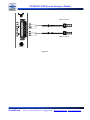
PT2060 Monitor
PT2060/91 SIM System Interface Module
User Manual
Installation, Operation, Maintenance
ProvibTech, Inc.
11011 Brooklet Drive, Suite 300, Houston, Texas 77099, USA
Phone: +1-713-830-7601, Fax: +1-281-754-4972, Email: [email protected] , Web: www.provibtech.com
PT2060-91-USR-A-11
COPY RIGHT PROVIBTECH 2007
PT2060/91 SIM System Interface Module
Contents
Receiving Inspection and Handling Guide......................................................................................................... 3
Inspection ................................................................................................................................................... 3
Handling and Storing Considerations......................................................................................................... 3
Module Introduction ........................................................................................................................................... 4
General Information.................................................................................................................................... 4
Specifications ............................................................................................................................................. 8
Electrical.............................................................................................................................................. 8
Environmental ................................................................................................................................... 10
Physical ............................................................................................................................................. 10
Configuration Setting and Application ............................................................................................................. 11
Configuration Information ......................................................................................................................... 11
Modbus TCP............................................................................................................................................. 11
Factory Default Communications Settings ............................................................................................... 11
Configuration Password and Control Password....................................................................................... 12
Communication with the SIM module....................................................................................................... 13
Rack Interconnection................................................................................................................................ 16
Mapping Modbus Registers...................................................................................................................... 18
Full Scale Data Range ............................................................................................................................. 19
Parameter Setting for the Dual Channels Phase Reference ................................................................... 20
PT2060/91 Operation ...................................................................................................................................... 24
Views of the Front Panel .......................................................................................................................... 24
I/O Module Description............................................................................................................................. 26
Protocols................................................................................................................................................... 32
Hardware Module Operation ........................................................................................................................... 39
PT2060/91 Field-wiring Diagram.............................................................................................................. 39
Field-wiring Diagram for PT2060/91......................................................................................................... 40
Maintenance .................................................................................................................................................... 51
Periodic Maintenance............................................................................................................................... 51
Preparation Work...................................................................................................................................... 51
Tool Preparations.............................................................................................................................. 51
Build of the Maintenance Environment ............................................................................................. 51
Software Preparation ........................................................................................................................ 52
PT2060 Phase Reference Testing ........................................................................................................... 52
Verifying Voltage of Back Panel ............................................................................................................... 54
Troubleshooting ............................................................................................................................................... 55
Test of Power-on ...................................................................................................................................... 55
System Event List (Read Only) ................................................................................................................ 55
Alarm Event List (Read Only)................................................................................................................... 55
Additional Information ...................................................................................................................................... 57
Ordering Information ................................................................................................................................ 57
Accessories .............................................................................................................................................. 57
Rack Address Setting ............................................................................................................................... 60
AppendixⅠ ...................................................................................................................................................... 62
ProvibTech
Phone: +1-713-830-7601 Fax: +1-281-754-4972
2
[email protected] , www.provibtech.com
PT2060/91 SIM System Interface Module
Receiving Inspection and Handling Guide
Inspection
Check the devices for possible damage that may have occurred from improper transport. Damages in transit
must be recorded on the transport documents. All claims for damages must be made without delay against
the shipper within 2 weeks after receipt of shipment at site.
Handling and Storing Considerations
PT2060 should be handled with care while unpacking and installation. Damage to PT2060 is typically caused
by rough handling, shock, or electrostatic discharge (ESD).
Be aware of the following precautions while unpacking and handling PT2060 Rack or any module.
9
Please pay attention to the sharp corners/sides of the rack to avoid any of injuries during the installation,
transporting and un-installation.
9
All circuit boards and electronic modules associated with this rack contain components which are
susceptible to damage caused by electrostatic discharge. It is necessary to discharge any static
electricity from yourself and your clothing before handling the rack.
9
Always keep the module in the protective antistatic bag whenever it is not installed in a system.
ProvibTech
Phone: +1-713-830-7601 Fax: +1-281-754-4972
3
[email protected] , www.provibtech.com
PT2060/91 SIM System Interface Module
Module Introduction
General Information
ProvibTech’s PT2060/91 SIM system Interface module is a communication and system management
module. The System Interface Module provides serial communications between the PT2060 Monitor System
and plant information systems such as a distributed control systems (DCS) or a programmable logic
controllers (PLC). The System Interface Module collects data from other modules in the rack over a
high-speed internal network and sends this data to the information system upon request.
The System Interface Module is also able to communicate via Ethernet with a host computer. The host
can be Modbus protocol based controllers or computers with PT2060 Rack Configuration and Data
Acquisition software.
The PT2060/91 SIM system Interface module can realize the following functions:
9
Control
9
9
9
9
9
Contacts
Rack Reset
Trip Multiply
Bypass
OK Relay
SIM has the following functions
9
9
Security
9
9
9
9
Control password
Configuration password
Factory password
Communications Ports
9
9
9
9
Front Panel RS-232 Port
Back Panel RS-485 Port
Back Panel RS-232 Port
Back Panel Ethernet Port
Event Lists
9
Alarm Event List
9
9
9
9
9
9
9
Communication with up-level control
system.
Configuration of the rack system,
each module and each channel.
Customization of the name for each
channel.
Storage of System Events and Alarm
Events.
Connection to other racks.
Dual phase references.
Speed output.
Signal of phase reference output with
peak to peak
Gap voltage output
Virtual address configuration
and mapping.
System Event List
ProvibTech
Phone: +1-713-830-7601 Fax: +1-281-754-4972
4
Figure 1
[email protected] , www.provibtech.com
PT2060/91 SIM System Interface Module
Hardware Considerations
The slots in the rack are numbered from 1 to 16, counting from left to right. The System Interface module
is always in slot 15.
Statuses
The System Interface Module returns both module and channel status. This section describes the
available status indicators and where they can be found.
Module Status
OK
This indicates if the System Interface Module is functioning correctly or not. A not OK status is returned
under the condition of Hardware Failure.
If the Module OK status goes not OK then the system OK Relay on the SIM system Interface module will
be driven not OK.
Channel Status
OK
This indicates whether or not a fault has been detected on the channel or within the module. If the
Channel OK status goes not OK then the system OK Relay on the SIM system Interface module will be driven
not OK.
ProvibTech
Phone: +1-713-830-7601 Fax: +1-281-754-4972
5
[email protected] , www.provibtech.com
PT2060/91 SIM System Interface Module
LED Descriptions
The LEDs on the front panel of the SIM system Interface module indicate the operating status of the
module as shown in the following figure.
PT2060/91
SIM
Figure 2
9
9
9
9
OK/IO LED
TRIP-MLT LED
BYPASS LED
CONFIG LED
ProvibTech
Phone: +1-713-830-7601 Fax: +1-281-754-4972
6
[email protected] , www.provibtech.com
PT2060/91 SIM System Interface Module
System Reset to Factory Setting
Modbus RTU RS-232/RS-485
Press the RESET button on the front panel of PT2060/91 before applying power and keep it pressed for
6 seconds after power is on. Some parameters of the SIM module will be reset to default setting such as:
9 Communication baud rate: 19200
9 2 stop bits, No parity bit
9 Control password: 1234
9 Configuration password: 1234
Modbus TCP
Press the RESET button on the front panel of PT2060/91 before applying power and keep it pressed for
6 seconds after power is on. Some parameters of the SIM module will be reset to default setting such as:
9 IP Address: 192.168.1.211
9 Subnet Mask: 255.255.255.0
9 Gateway Mask: 192.168.1.1
9 Control password: 1234
9 Configuration password: 1234
Phase Reference
As a required function to each rack, dual phase references are integrated into the SIM module as a
default setting. The two phase reference channels will supply phase reference information to all the channels
on the rack.
Other Information
The slots in a standard 19″ rack are numbered from 1 to 16, counting from left to right. The PT2060/91
system interface module can be mounted in slot 15. The slots in a 12″ rack are numbered from 1 to 9,
counting from left to right. The PT2060/91 SIM system Interface module can be mounted in slot 8.
ProvibTech
Phone: +1-713-830-7601 Fax: +1-281-754-4972
7
[email protected] , www.provibtech.com
PT2060/91 SIM System Interface Module
Specifications
Electrical
Power supply:
Internally converted by the rack power supply module
3.7W total typical for each module
Phase reference signal Input:
Input impedance:
> 20KΩ
Input voltage range:
magnetic pickup: +15VDC ~ -15VDC
Proximity probes: 0 ~ -24VDC
Input signal frequency: 0~20kHz
Sensors for Phase reference:
Proximity probes; magnetic pickup sensor (nonsupport for previous version)
Parameters for Proximity probes:
Input frequency:
The PT2060/91 module supports 1 - 255 events per revolution with a
maximum full scale range of 60000 rpm.
Valid frequency: >0.0167Hz
Threshold:
Auto: > 2.0V pk-pk signal amplitude (at least 2Hz), Trigger level is calculate
automatically.
Manual: > 0.6V pk-pk signal amplitude (at least 0.017Hz). Trigger level
programmable from -17VDC to -3VDC.
Hysteresis:
0.5 - 2.5 V user selectable
Power supply:
-24VDC for proximity probe driver.
current limited. Less than 50mA on each channel
Parameters for magnetic pickup:
Input frequency:
The PT2060/91 module supports 1 - 255 events per revolution with a
maximum full scale range of 60000 RPM.
Valid frequency: >3.3Hz(least 2Vpkpk)
Hysteresis:
Power supply:
0.5 - 2.5 V user selectable
Need no power.
Phase Reference buffer:
On the front panel, each channel has one BNC connector. Original phase
reference signal can be selected to output. modulated square wave can be
selected to output for previous version.
amplitude of signal: -23V~14V
Output Impedance:
150Ω
Speed output:
The PT2060/91 module provides the function to measure machine speed in
RPM from the two transducers. Input range of 1 to 1,200,000 RPM (0.017 Hz
ProvibTech
Phone: +1-713-830-7601 Fax: +1-281-754-4972
8
[email protected] , www.provibtech.com
PT2060/91 SIM System Interface Module
to 20 kHz), the measurable RPM scale is from 1 to 60000 RPM (0.017 Hz to
1000 Hz), The real-time updating RPM can be observed from the PT2060
Configuration software.
Accuracy:
±1 RPM
Pk to Pk value:
When the input frequency of transducer is more than 0.1 Hz, the PT2060/91
module will automatically calculate the peak-to-peak swing of the sensor’s
signal, and display the Pk to Pk Value via PT2060-CFG.
Gap voltage:
When frequency of the input Proximity transducer’s signal is more than 0.5 Hz,
the PT2060/91 module will display the gap voltage of the Proximity transducer
via PT2060-CFG., otherwise, display the real time Value when frequency of the
input Proximity sensor’s signal is less than 0.5 Hz.
LED Indicators:
OK/IO:
TRIP-MLT:
BYPASS:
CONFIG:
green
It Indicates that the PT2060/91 Module is operating correctly When the OK/IO
led is Flashing. If the OK/IO led is off, please check probe driver and cable of
Phase reference.
red
It will go on when system is in Trip-MLT.
red
It will go on when system is in BYPASS.
green
It will go on when the system is in CONFIG, And OK/IO LED is on but not
flashes.
Modbus communication:
RS-232 (2):
one on front and one on back panel.
RS-485 (1):
on the back panel of module. The available baud rate values are: 1200, 2400,
4800, 9600, 19.2 k, 38.4 k and 115.2 k baud. RS-485 cable can run up to
maximum 1220 meters (4000 ft).
Ethernet (1):
On the back panel of module, 10Mbps, IEEE802.3. There is only (1) active
Modbus communication port.
System Alarm:
There will be a dedicated relay for indication of system OK status. This is an energized relay; it
indicates a system error for one of the system components when the energized relay changes status.
Relays:
Seal:
Epoxy
Capacity:
2A/240VAC or 2A/24VDC, resistive load
Relay type:
SPDT
Isolation:
1000VDC
Approvals:
CE;
ProvibTech
Phone: +1-713-830-7601 Fax: +1-281-754-4972
9
[email protected] , www.provibtech.com
PT2060/91 SIM System Interface Module
CSA:
Non-incendive,classI,div.2,Grps.ABCD,T4@Ta= -40℃ to +75℃
Certificate Number: 2011996
Environmental
Temperature:
Operation:
Storage:
-20℃ to +65℃
-40℃ to +85℃
Humidity:
95% non-condensing
Physical
Each module comes with two components the front panel assembly and the back panel assembly.
Dimensions and Location:
241mm (9.5in) X 24.5mm (0.96in)
This module has to be located in the second slot from the right hand side of the rack (slot 15)
Weight:
ProvibTech
1.2kg (2.01 lbs)
Phone: +1-713-830-7601 Fax: +1-281-754-4972
10
[email protected] , www.provibtech.com
PT2060/91 SIM System Interface Module
Configuration Setting and Application
Configuration Information
This section describes how the System Interface Module is configured using the PT2060 Configuration
Software. It also describes any configuration considerations associated with this module. For the details
regarding the operation of software, refer to the PT2060 Monitoring System Rack Configuration and Utilities
Guide and the Rack Configuration Software.
Application Alert
You can’t use Modbus RS-232/RS-485 and Modbus TCP at the
same time! Only one communications interface can be used at a
time!
Modbus TCP
Modbus TCP is an Internet protocol. Ethernet is a long-standing office networking protocol that has
gained universal world-wide acceptance. It is also an open standard that is supported by many
manufacturers and its infrastructure is widely available and largely installed. Consequently, its TCP/IP suite
of protocols is used world-wide and even serves as the foundation for access to the World Wide Web as
many devices already support Ethernet.
For PT2060/91 SIM System Interface Module, an Ethernet Crossover cable is needed to connect the
system to a PC directly. The Speed of communication can be up to 10Mb/s. The PT2060/91 SIM System
Interface Module is able to communicate via Ethernet with up to five hosts. Hosts can be Modbus TCP
protocol based.
Factory Default Communications Settings
Modbus RTU RS-485 / RS-232
Communication setting:
Rack Address setting:
Control password:
Configuration password:
19200bps, 8 data bits, no parity, 2 stop bits
PT2060/91 module’s Rack Address is 1.
1234
1234
Modbus TCP
IP Address setting:
Subnet Mask setting:
Gateway Address setting:
Rack Address setting:
Control password:
Configuration password:
192.168.1.211
255.255.255.0
192.168.1.1
PT2060/91 module’s Rack Address is 1.
1234
1234
ProvibTech
Phone: +1-713-830-7601 Fax: +1-281-754-4972
11
[email protected] , www.provibtech.com
PT2060/91 SIM System Interface Module
Configuration Password and Control Password
To enhance the security of PT2060 operation, the system involves a control password and configuration
password.
Control Password:
If the Control password entered in this field does not match the password entered in the Rack
Configuration some parameters, such as communication baud rate and Modbus registers, can not be
modified.
Figure 3
Configuration Password
If the Configuration password entered in this field does not match the password entered in the Rack
Configuration some operations, such as modification of other modules, are restricted.
Figure 4
ProvibTech
Phone: +1-713-830-7601 Fax: +1-281-754-4972
12
[email protected] , www.provibtech.com
PT2060/91 SIM System Interface Module
Communication with the SIM module
The SIM module can communication to the upper-level PLC/DCS systems via Modbus RTU
communication protocol. Information about the system, rack, modules, channels, and sensors can be
collected and communicated to the control system. It can also perform system reset, trip-multiply, and
bypass via Modbus.
The communication port can perform only one communication function, such as a Modbus connection
to control system or a PT2060-MON system. Further communication and Ethernet connection can be done
via the communication module PT2060/91. Please refer to this module for more details.
Setting Communication Parameters
The PT2060 Communication Setup lets you set the communication parameters for the HOST Computer
on the System interface Module.
Communication with Modbus RTU
Figure 5
Parity Used for error checking
None:
No parity error checking is used.
Odd:
Each word has an odd number of 1 bit.
Even:
Each word has an even number of 1 bit.
Baud Rate:
This is the rate of communication between the System Interface Module and the DCS.
The available values are: 1200, 2400, 4800, 9600, 19.2K, 38.4K, and 115.2K baud.
Stop Bits:
Signifies the end of the character. One or two bits can be used.
ProvibTech
Phone: +1-713-830-7601 Fax: +1-281-754-4972
13
[email protected] , www.provibtech.com
PT2060/91 SIM System Interface Module
Communication with Modbus TCP
Figure 6
The PT2060/91 SIM System Interface Module’s parameters can be set through the Ethernet Port on the
Back board.
IP Address
IP (Internet Protocol) Address is the unique address for an Ethernet network device. The IP address is a
string of 4 numbers each from 0 to 255. For networks managed through an Information Technology
department, consult the network administrator for a valid IP address.
For example: 192.168.1.211
Subnet Mask
The Subnet Mask identifies which bits of the IP address are address bits for the physical network.
Typically, the Subnet Mask is the same for the LAN (local area network), however, consult the network
administrator for valid setting.
For example: 255.255.255.0
Gateway Address
Consult your network administrator for valid setting.
For example: 192.168.1.1
System Configuration
Each channel can be configured by PT2060-CFG through SIM module. Two RS-232 ports located on
both front and back panel can be accessed for configuration.
History Event Storage
The PT2060/91 SIM system Interface module will store up to 500 system events and alarm events.
These events can be accessed from the PT2060/91 through Modbus or PT2060-CFG system configuration
software.
ProvibTech
Phone: +1-713-830-7601 Fax: +1-281-754-4972
14
[email protected] , www.provibtech.com
PT2060/91 SIM System Interface Module
Channel name customization
The PT2060/91 SIM system Interface module supports the function to customize name for each
channel. It is convenient for user to identify channels in the work field. Refer to the following figure, the length
for each name can maximize 30 characters. Click the right button on the slot which to be configured in the
rack, choose set channel names, the following figure can be opened.
Figure 7
Power Configuration
This section describes the options available on power module configuration screen. The PT2060/91
SIM system Interface module supports the function to configure power type, the user can configure the
power module type base on the Rack power Configuration.
The following power supplies can be installed in the PT2060 rack:
Figure 8
ProvibTech
Phone: +1-713-830-7601 Fax: +1-281-754-4972
15
[email protected] , www.provibtech.com
PT2060/91 SIM System Interface Module
Rack Interconnection
Several racks can be connected via their RS-485 PORTs based on standard Modbus protocol. Each
rack should be assigned a different address. The system configuration can be done through one of the
RS-485 Ports on the connected rack system.
SYSTEM
SYSTEM
SYSTEM
SYSTEM
INTERFACE
INTERFACE
INTERFACE
INTERFACE
91 SIM
91 SIM
91 SIM
91 SIM
ETHERNET
ETHERNET
ETHERNET
ETHERNET
RS485
RS485
RS485
RS485
NC
ARM
NC
ARM
NC
ARM
NO
NO
NO
COM
COM
COM
NC
ARM
NO
COM
RS232
RS232
RS232
SHIELD
SHIELD
SHIELD
SHIELD
PT2060-009108-A00
RS232
RS485 HUB
Figure 9
ProvibTech
Phone: +1-713-830-7601 Fax: +1-281-754-4972
16
[email protected] , www.provibtech.com
PT2060/91 SIM System Interface Module
Several racks can be connected via their Ethernet PORTS based on standard Modbus protocol. Each
rack should be assigned a different address. The system configuration can be done through one of the
Ethernet Ports on the connected Ethernet switch.
SYSTEM
SYSTEM
SYSTEM
SYSTEM
INTERFACE
INTERFACE
INTERFACE
INTERFACE
91 SIM
91 SIM
91 SIM
91 SIM
ETHERNET
ETHERNET
ETHERNET
ETHERNET
RS485
RS485
RS485
RS485
NC
ARM
NC
ARM
NC
ARM
NO
NO
NO
COM
COM
COM
NC
ARM
NO
COM
RS232
RS232
RS232
RS232
SHIELD
SHIELD
SHIELD
SHIELD
PT2060-009104-AXX
Figure 10
ProvibTech
Phone: +1-713-830-7601 Fax: +1-281-754-4972
17
[email protected] , www.provibtech.com
PT2060/91 SIM System Interface Module
Mapping Modbus Registers
The real address of the dispersed channel measured value can be arbitrarily mapped to continuous
virtual register addresses by PT2060-CFG. It improves the communication efficiency and realizes the data
monitoring rapidly and perfectly.
Mapping Modbus Registers is a reserved area of the Modbus register map that consists of 512
registers. These registers allow you to assign important status to consecutive registers so that the
communication with the PT2060 rack is more efficient and the need for supporting hardware is reduced.
Users can click the channel or slot that you want to configure in the left window, and drag and drop the
mouse to the responding virtual address in the right hand window. Consequently, click the Download button
when you finish the configuration of registers, assign all dispersed registers to a set of consecutive registers,
and get all values from virtual addresses configured expediently. If you want to check the configuration of the
modbus registers, you can click the Upload button to get the current configuration of modbus registers.
For example, we can configure Slot3_Channel6’s register 30575 to any register between 31501 and
32012 and its Channel’s status register 44054 can be also configured to the corresponding register between
45017 and 45272. Please refer to the following picture.
Figure 11
Configure a Communication interface Module by using the PT2060 Rack Configuration Software to
complete the following tasks:
9 Set the communication parameters for the ports on the System interface Module.
9 Assign data from rack modules to reserved addresses (Configurable Modbus Registers) in the System
interface Module.
ProvibTech
Phone: +1-713-830-7601 Fax: +1-281-754-4972
18
[email protected] , www.provibtech.com
PT2060/91 SIM System Interface Module
Full Scale Data Range
A value between 128 and 16384 is the maximum value in the full-scale range. The Current Proportional
Values and the Primary Values will be scaled between 0 and the selected value and the result will be given via
modbus. The default is 16384.
Figure 12
Overall = Modbus Output (full scale high – full scale low) / Proportional full scale range + full scale low.
or example, for a monitor channel that is operating as shown in the following table
Parameter
Value
Direct Full-scale range
Modbus output
Proportional Full-scale Range
0 – 10 mil
8192
16384
Calculate the output as follows:
Overall = 8192 * (10 – 0) /16384 + 0 = 5 mil
As another example lets say that we have a range of 0-10mils and we are reading 4 mils. Then we
can say that:
Parameter
Value
Direct Full-scale range
Overall
Proportional Full-scale Range
0 – 10 mil
4 mil
16384
Output = Full scale range * (overall – full scale low) / (full scale high – full scale low)
Output = 16384(4-0)/(10-0)
= 16384 (0.4)
= 6553.6 (or 6554)
So the value sent to the PLC will be 6554.
ProvibTech
Phone: +1-713-830-7601 Fax: +1-281-754-4972
19
[email protected] , www.provibtech.com
PT2060/91 SIM System Interface Module
Parameter Setting for the Dual Channels Phase
Reference
Phase reference works in two modes, manual and auto.
Channel Parameter setup:
Channel No
PT2060/91 SIM system interface module has two phase reference channels. Choose any one to
configure.
Channel Enable
This check box enables or disables a phase reference channel. If no phase reference transducer is
connected to this channel, then this box should be unchecked.
Trigger voltage
The Trigger Value is the nominal voltage that the peak-to-peak swing of the sensor’s signal is centered
about. If Auto threshold is selected, the module will automatically determine the peak-to-peak swing of the
sensor’s signal and set the Trigger value to the mid point. If Manual Threshold is selected, the user can input
the Trigger value for the module to use.
Teeth per cycle
It refers to the teeth number on the gear. The integer number of input pulses per shaft revolution when
observing an integral multi-event signal source, such as a gear. The Events per Revolution may be specified
as an integer between 1 and 255. By default it is1.
Hysteresis voltage
It is the voltage level above and below the threshold value which is required to trigger the input signal
from the transducer. The larger the hysteresis, the greater the immunity to noise on the input signal. When the
input signal passes the threshold voltage plus 1/2 of the Hysteresis voltage, the signal goes high. When the
input signal returns to the threshold voltage minus 1/2 of the Hysteresis voltage, the signal goes low. By
default it is 1V. The User could modify it in the range of 0.5V-2.5V. This item has no relation to shaft vibration
measuring.
GAP Value
For proximity probes, this stands for the distance between the top of the probes and the measured
surface. Default factory setting of GAP high is -24V, GAP low -1V.
Transducer Degrees
This specifies the transducer location on the machine. The Transducer angle is 0 to 180 degrees left or
right , The following figure shows this for horizontal shafts.
ProvibTech
Phone: +1-713-830-7601 Fax: +1-281-754-4972
20
[email protected] , www.provibtech.com
PT2060/91 SIM System Interface Module
Figure 13
Threshold type
For proximity probes, the threshold options can be Auto threshold or Manual threshold. For magnetic
pickup, threshold is only Auto threshold.
Auto: The trigger threshold is automatically set to a value that is midway between the most positive peak
and the most negative peak of the input signal. This value tracks any changes in the input signal. Auto
threshold requires minimum signal amplitude of 2Vpp and minimum frequency of 2 Hz.
Threshold type
For proximity probes, the threshold options can be Auto threshold or Manual threshold. For magnetic
pickup, threshold is only Auto threshold.
Signal Polarity
Notch: An output pulse, produced for use by the monitors that is triggered by the leading edge of a
negative-going pulse in the input signal. If a magnetic pickup is used, set Notch/Projection setting to Notch.
Projection: An output pulse, produced for use by the monitors that is triggered by the leading edge of a
positive-going pulse in the input signal.
ProvibTech
Phone: +1-713-830-7601 Fax: +1-281-754-4972
21
[email protected] , www.provibtech.com
PT2060/91 SIM System Interface Module
Figure 14
Manual: The trigger threshold is set by the user to any value in the range of -3V to -17 volts. Manual
threshold requires minimum signal amplitude of 0.6 VPP.
Figure 15
At first, measure and observe the phase signal which you want to use by oscilloscope, record the
maximum voltage and minimum voltage.
Then, calculate the Trigger voltage value. Trigger voltage value = (maximum voltage + minimum voltage)
/ 2. Select Manual item and choose Channel no. in the window above.
ProvibTech
Phone: +1-713-830-7601 Fax: +1-281-754-4972
22
[email protected] , www.provibtech.com
PT2060/91 SIM System Interface Module
At last, input Trigger voltage value, click Download button to set the parameters.
It is recommended that parameters should be verified after they have been configured.
ProvibTech
Phone: +1-713-830-7601 Fax: +1-281-754-4972
23
[email protected] , www.provibtech.com
PT2060/91 SIM System Interface Module
PT2060/91 Operation
Views of the Front Panel
PT2060/91
SIM
Figure 16
ProvibTech
Phone: +1-713-830-7601 Fax: +1-281-754-4972
24
[email protected] , www.provibtech.com
PT2060/91 SIM System Interface Module
1.
OK/IO LED
OK/IO LED will go on when PT2060/91 works well. If OK/IO LED is off, please check probe driver and
cable of Phase reference.
2.
TRIP-MLT LED
It will go on when system is in Trip-MLT
3. BYPASS LED
It will go on when in BYPASS.
4. CONFIG LED
It will go on when the system is in CONFIG, And OK/IO LED is on but not flashes.
5.
RESET
Enable the system reset.
6. RS-232 port
PT2060 should connect with the up-controller by this port.
7. Phase Reference Output
Each channel has one BNC connector. The output is the Original phase reference signal. The output is
the phase reference signal for previous version.
ProvibTech
Phone: +1-713-830-7601 Fax: +1-281-754-4972
25
[email protected] , www.provibtech.com
PT2060/91 SIM System Interface Module
I/O Module Description
The PT2060 has two RS-232 ports, an
RS-485 port, and an Ethernet port. Via these a
computer can communicate with PT2060.
RS-232 ports and RS-485 port uses optical
isolators, Ethernet port uses an isolating
transformer
This section describes how to use the
connectors on the I/O modules and how to
wire.
1.
SYSTEM
SYSTEM
INTERFACE
INTERFACE
91 SIM
91 SIM
ETHERNET
ETHERNET
RS485
RS485
Ethernet
NC
ARM
NC
ARM
The PT2060 can connect with the Network
through the Ethernet port. It supports TCP/IP
protocols. RJ45 connector is used in most
application.
NO
NO
COM
COM
RS232
RS232
SHIELD
SHIELD
Previous version
Figure 17
ProvibTech
Phone: +1-713-830-7601 Fax: +1-281-754-4972
26
[email protected] , www.provibtech.com
PT2060/91 SIM System Interface Module
2.
RS-485
The PT2060 can connect with the PT2060-CFG via RS-485. A PT2060 rack has two pairs of RS-485
signals, 485A1-485B1 and 485A2-485B2.
The communication rate is limited by the baud rate selected between the host computer and the
PT2060 SIM system Interface module. Connect 485A1 with the Modbus RS-485 I/O converter 485-A, and
485B1 with the Modbus RS-485 I/O converter 485-B. Communication can also be established through
485A2-485B2 pair with the Modbus RS-485 I/O converter.
When connecting the Modbus RS-485 I/O converter to a host device or to another I/O module, the
connections are made per the diagram below. See the following table for connector designations.
Figure 18
RS-485 port definition:
3.
Pin number(9pin)
Definition
6
485A1
4
485B1
9
485A2
3
485B2
5
COM
TRIP-MLT alarm, BYPASS and OK RELAY
Activate the TRIP-MLT alarm and BYPASS by shorting the respective contact to COM.
The OK Relay is normally energized and is used to indicate whether the PT2060 Monitoring System is
ProvibTech
Phone: +1-713-830-7601 Fax: +1-281-754-4972
27
[email protected] , www.provibtech.com
PT2060/91 SIM System Interface Module
OK. The OK relay will change state with the failure of any module.
The following diagrams show the different ways the OK Relay can be wired:
Normally Energized
NC
No power/Shelf State
ARM
NO
NC
With power/OK Condition
ARM
NO
With power/Not OK Condition
NC
ARM
NO
Figure 19
NO
ARM
NC
Normally Open.
Armature.
Normally Closed.
COM
RST_BY
Common
Enable Hardware Bypass status (restrain the alarm of Alert and Danger) when it is in contact
with COM
Enable the Trip Multiply function (set up using PT2060 Configuration Software) when it is in
contact with COM.
TRIP_MLT
NC
ARM
NO
COM
Figure 20
ProvibTech
Phone: +1-713-830-7601 Fax: +1-281-754-4972
28
[email protected] , www.provibtech.com
PT2060/91 SIM System Interface Module
4.
RS-232
The PT2060 can connect with the upper level controller via RS232. The cable will go between the
RACK RS-232 connector on PT2060 System rack and the HOST computer.
The communication rate is limited by the baud rate selected between the host computer and the PT2060
SIM system Interface module.
PT2060-009107-A00
RS232
Figure 21
1) The Host Computer
2) Cross serial cable
3) RS-232 Port
RS-232 port definition:
ProvibTech
Pin number(9pin)
signal
Name
2
RX
Receiving
3
TX
Transmitting
5
COM
Common reference
Phone: +1-713-830-7601 Fax: +1-281-754-4972
29
[email protected] , www.provibtech.com
PT2060/91 SIM System Interface Module
5.
Phase reference input port
The PT2060/91 has two phase reference input channels as shown below. Phase reference outputs can
be observed with an oscilloscope from the BNC which is fixed in the front panel. Figure 22 is for previous
version.
2
8
1
0
M
T
COM
COM
SIG
PROVIBTECH
POW(-24)
5mm/8mm Driver
PROBE CABLE
PROBE
PROBE CABLE
PROBE
SENSITIVITY:
8mV/um
200mV/mil
PROVIBTECH
2
8
1
0
M
T
PROVIBTECH
POW(-24)
COM
COM
SIG
5mm/8mm Driver
SENSITIVITY:
8mV/um
200mV/mil
PROVIBTECH
SHIELD
Figure 22
2
8
1
0
M
T
COM
COM
SIG
PROVIBTECH
POW(-24)
5mm/8mm Driver
PROBE CABLE
PROBE
PROBE CABLE
PROBE
SENSITIVITY:
8mV/um
200mV/mil
PROVIBTECH
2
8
1
0
M
T
COM
COM
SIG
PROVIBTECH
POW(-24)
5mm/8mm Driver
SENSITIVITY:
8mV/um
200mV/mil
PROVIBTECH
SHIELD
Figure 23
ProvibTech
Phone: +1-713-830-7601 Fax: +1-281-754-4972
30
[email protected] , www.provibtech.com
PT2060/91 SIM System Interface Module
Magnetic Pickup
Magnetic Pickup
SHIELD
Figure 24
ProvibTech
Phone: +1-713-830-7601 Fax: +1-281-754-4972
31
[email protected] , www.provibtech.com
PT2060/91 SIM System Interface Module
Protocols
Modbus Protocol
Register Map
This section describes the function codes, addressing notation, and registers supported by the
Communication Module.
Supported Function Codes
Modbus Function Code
Communication Module Data
Code Meaning
02
Read Input Status
Rack, Module, and Channel Status
03
Read Holding Registers
Full-scale Data Range, Module Type ,Password Setup
Success, Get time from the Monitor
04
Read Input Registers
Overall and GAP Voltage, Time for the Last Reading
06
And
16
Preset Single Register
And
Preset Multiple
Channel Configuration, Monitor Trip Multiply, Monitor
Alarm Inhibit, Monitor Reset, Communication
Baud-rate, Stop Bit, Parity Bit, IP Address Setup
Monitor Time and Date ,Password Setup
17
Report Slave ID
Family ID
ProvibTech
Phone: +1-713-830-7601 Fax: +1-281-754-4972
32
[email protected] , www.provibtech.com
PT2060/91 SIM System Interface Module
Register allocation
Data Type
Function
Code
Format of the
request address
(0 is the base)
Address allocation
MODBUS format
(1 is the base)
Overall and GAP Voltage
Time for the Last Reading
4
4
500-1011
1012-1018
30501-31012
31013-31019
Module Status
Channel Status
Rack Status
2
2
2
10-137
138-2185
2186-2193
10011-10138
10139-12186
10187-12194
Channel Configuration
6
0-1
40001-40002
Password Setup Success
3
11
40012
Get time from the Monitor
Monitor Trip Multiply
Monitor Alarm Inhibit
Monitor Reset
Success of the Last Command
Full-scale Data Range
Input Control Password
Real-time Value
(virtual register)
Channel Status
(virtual register)
3
6
6
6
3
3,6
16
4
80-86
94
95
96
100-112
113
173-176
1500-2011
40081-40087
40095
40096
40097
40101-40113
40114
40174-40177
31501-32012
3
5016-5271
45017-45272
Repeated Channel Status
Repeated Overall and GAP
Voltage
3
3
4016-4271
1000-1512
44017-44272
41001-41512
ProvibTech
Phone: +1-713-830-7601 Fax: +1-281-754-4972
33
[email protected] , www.provibtech.com
PT2060/91 SIM System Interface Module
Status List
Signal module’s status (Read Only)
Address: 10139 - 12186
Channel’s first address=10139+128(slot-1) + 8(ch-1)
Each slot takes up to 128 data address. Each module can have up to 16 channels.
Each channel takes up to 8 data address that is 8 status.
Slot = 1-16
Ch = 1-16 (channel)
Example: In First channel at first slot (Slot 1 Ch 1).
10139=0/1
OK/NOT OK
10140=0/1
NOT Alert/Alert
10141=0/1
NOT Danger/Danger
10142=0/1
NOT Bypass/Bypass
10143=0/1
NOT Trip Multiply/Trip Multiply
10144=0/1
NOT Off/Off
10145=0/1
Gap Ok/Gap Not Ok
10146
Un-used
Status parameter:
NOT OK:
Alert:
Danger:
Bypass:
Trip Multiply:
Gap not ok:
channel not working right
channel in the first alarm status (alert)
channel in the second alarm status (danger)
channel is in bypass status. Alarms will not be engaged (inhibit)
the set point of the alarms has been increased to double or triple depend on
configuration
the sensor is not working properly
Bit
0
1
2
3
4
5
6
7
ProvibTech
Channel Statuses
Channel not OK
Channel Alert / Alarm 1
Channel Danger / Alarm 2
Channel In Bypass Mode
Channel Trip Multiply Mode
Channel Off
Channel Gap
----
Phone: +1-713-830-7601 Fax: +1-281-754-4972
34
[email protected] , www.provibtech.com
PT2060/91 SIM System Interface Module
Starting Addresses for Channel Statuses
PT2060 Rack Slot
Number
1
2
3
4
5
6
7
8
9
10
11
12
13
14
15
16
Modbus
PC
Format
10139
10267
10395
10532
10651
10779
10907
11035
11163
11291
11419
11547
11675
11803
11931
12059
Query Format
138
266
394
531
650
778
906
1034
1162
1290
1418
1546
1674
1802
1930
2058
Signal module status (Read Only)
Address: 10011- 10138
Total 256 address. Each module takes up to 8 addresses (8 status)
First address on each module = 10011+8(slot-1)
Slot = 1-16
Example: status of the first module
10011=0/1
OK/NOT OK
10012=0/1
NOT Alert/Alert
10013=0/1
NOT Danger/Danger
10014=0/1
NOT Bypass/Bypass
10015=0/1
NOT Trip Multiply/Trip Multiply
10016=0/1
NOT Off/Off
10273=0/1
Gap Ok/Gap Not Ok
10274
Un-used
Status parameter:
NOT OK: module is not working properly.
Alert: some channels on the module are in the first alarm (alert).
Danger: some channels on the module are in the second alarm (danger).
Bypass: some channels are under bypass (alarm-inhibit).
Trip Multiply: the alarm set-point has been doubled or tripled.
Off: some channels are not working.
Gap Not Ok: some sensors are not working properly.
ProvibTech
Phone: +1-713-830-7601 Fax: +1-281-754-4972
35
[email protected] , www.provibtech.com
PT2060/91 SIM System Interface Module
Rack monitor address (Read Only)
12187 =0/1
12188 =0/1
12189 =0/1
12190 =0/1
12191 =0/1
12192 =0/1
12193 =0/1
12194
OK/NOT OK
NOT Alert/Alert
NOT Danger/Danger
NOT Bypass/Bypass
NOT Trip Multiply/Trip Multiply
NOT Off/Off
Gap Ok/Gap Not Ok
Un-used
Status parameter:
NOT OK: module is not working properly.
Alert: some channels on the module are in the first alarm (alert).
Danger: some channels on the module are in the second alarm (danger).
Bypass: some channels are under bypass (alarm-inhibit).
Trip Multiply: the alarm set-point has been doubled or tripled.
Off: some channels are not working.
Gap Not Ok: some sensors are not working properly.
Rack monitor parameter list
Channel Setup
REG=40001[bit15-0] =1-17: Slot
REG=40002[bit15-0] =1-16: Channel
Password Setup OK
REG=40012[bit15-0] =0-3: password information
0: Not Ok
1: OK
Time and Date (Read Only)
Enquiry for the time and the date of the monitor
REG=40081[bit15-0] =0-99: year
REG=40082[bit15-0] =1-12: Month
REG=40083[bit15-0] =1-31: Day
REG=40084[bit15-0] =0-23: Hours
REG=40085[bit15-0] =0-59: minutes
REG=40086[bit15-0] =0-59: Seconds
REG=40087[bit15-0] =0-100: 1/100 second
ProvibTech
Phone: +1-713-830-7601 Fax: +1-281-754-4972
36
[email protected] , www.provibtech.com
PT2060/91 SIM System Interface Module
Trip Multiply (Read/Write)
REG=40095[BIT15-0] =0: Rack Not Trip Multiply
REG=40095[BIT15-0] =1: Rack Trip Multiply
Alarm Inhibit (Bypass) (Read/Write)
REG=40096[BIT0] =0/1: Alarm/Alarm bypass
Monitor Reset (Write Only)
REG=40097[BIT0] =0/1: Alarm not reset /alarm reset
Full Scale Range
REG=40114[bit15-0] = 4096~16384
A value between 4096 and 16384 that is the maximum value in the full-scale range. The Current
Proportional Values and the Primary Values will be scaled between 0 and the selected value.
Input Control Password: Total 8 Registers(Write Only)
REG=40174-40177;
40174[bit15-8] = ASCII Code //first ASCII code of control password of rack
40174[bit7-0] = ASCII Code //second ASCII code of control password of rack
40175[bit15-8] = ASCII Code //third ASCII code of control password of rack
40175[bit7-0] = ASCII Code //fourth ASCII code of control password of rack
40176[bit15-8] = ASCII Code //fifth ASCII code of control password of rack
40176[bit7-0] = ASCII Code //sixth ASCII code of control password of rack
40177[bit15-8] = ASCII Code //seventh ASCII code of control password of rack
40177[bit7-0] = ASCII Code //eighth ASCII code of control password of rack
Overall and Gap voltage (Read Only)
address = 30501+32(slot-1)+2(ch-1)+ n
slot: 1-16
ch: 1-16
n:parameters.
0: Overall
1: Gap voltage
Example:
REG=30501: overall of the first channel on the first slot.
REG=30502: gap voltage of the first channel on the first slot.
The unit of the gap voltage is in mV. It can be from 0 to full scale.
ProvibTech
Phone: +1-713-830-7601 Fax: +1-281-754-4972
37
[email protected] , www.provibtech.com
PT2060/91 SIM System Interface Module
The value to PLC = Full scale range * (overall – full scale low) / (full scale high – full scale low)
REG=31013[0-99]: year
REG=31014[1-12]: month
REG=31015[1-31]: day
REG=31016[0-23]: hour
REG=31017[0-59]: minute
REG=31018[0-59]: second
REG=31019[0-100]: 1/100 second
Last Read Proportional Time Stamp
Last Read Proportional Value
or Status Time Stamp Address
Field Name
Code
Range
Notes
1012
1013
1014
1015
1016
1017
1018
Year
Month
Day
Hour
Minute
Second
1/100 Second
00 -99*
1 - 12
1 - 31
0 - 23
0 - 59
0 - 59
0 - 99
Months are in
sequential order
(e.g. 1 = Jan)
31013
31014
31015
31016
31017
31018
31019
24-hour clock: 12
= Noon and 00 =
Midnight
* Year = 00 implies the year 2000
Real-time Value (Virtual register)
The Real-time Value (Virtual register) can be mapped arbitrarily by The PT2060 CFG, The real address of
the dispersed channel measured value can be configured in the continuous virtual register address via
PT2060-CFG, in order to increase communication efficiency.
REG=31501 [bit15-0] - REG=32012 [bit15-0]
Channel Status (Virtual register)
REG=45017 [bit15-0] - REG=45272 [bit15-0]
Channel Status (Virtual register) can be mapped arbitrarily by PT2060-CFG, For the convenience of the
user the real address of channel status can be configured in the continuous virtual register address via
PT2060-CFG..
Repeated Channel Status
The repeated data registers contain duplicated data in different registers for some Modbus devices that
only support the 4XXXX series registers, so that we can get channel status data expediently.
Repeated Overall and GAP Voltage
The repeated data registers contain duplicated data in different registers for some Modbus devices that
only support the 4XXXX series registers, so that we can get Overall and GAP Voltage expediently.
ProvibTech
Phone: +1-713-830-7601 Fax: +1-281-754-4972
38
[email protected] , www.provibtech.com
PT2060/91 SIM System Interface Module
Hardware Module Operation
PT2060/91 Field-wiring Diagram
SYSTEM
SYSTEM
INTERFACE
INTERFACE
91 SIM
91 SIM
ETHERNET
ETHERNET
Common industry interfaces are provided on
the back panel. Figure 25 is the diagrammatic
sketch.
1. Ethernet
It is used to connect PT2060 with the
Network.
2.
RS-485
It is used to connect PT2060 could connect
with the up-controller.
3.
TRIP-MLT alarm, BYPASS and OK RELAY
Affect the TRIP-MLT alarm and BYPASS by
this.
The OK Relay is normally energized and is
used to indicate whether the PT2060
Monitoring System is OK.
4.
RS-232
This is used to connect
upper-controller.
RS485
RS485
NC
ARM
NC
ARM
NO
NO
COM
COM
RS232
RS232
5.
PT2060 with the
Reference input port
PT2060/91 has two phase reference input
channels as shown above.
SHIELD
SHIELD
Previous version
Figure 25
ProvibTech
Phone: +1-713-830-7601 Fax: +1-281-754-4972
39
[email protected] , www.provibtech.com
PT2060/91 SIM System Interface Module
Field-wiring Diagram for PT2060/91
Modbus TCP:
Please refer to the following diagram, connect all rack Ethernet Ports with Switch, and connect
PC’s Ethernet Port with Switch. Communication can be established via different IP Addresses.
PT2060 default setting:
IP Address setting:
Subnet Mask setting:
Gateway Address setting:
Rack Address setting:
192.168.1.211
255.255.255.0
192.168.1.1
PT2060/91 module’s default Rack Address is 1
The user can use the Ethernet direct communication Cable (PT2060-009105) to connect PLC, DCS, or
PC with PT2060. One end shall be connected to PLC, DCS, or PC, and the other end connected to PT2060
SIM system Interface module. Configure the PC of the user as following:
First, right click my network places on the desktop, select properties to open a Local
figure 26
Area Connection Window and right click Local Area Connection,
Figure 27
select properties to open Local Area Connection’s window,
ProvibTech
Phone: +1-713-830-7601 Fax: +1-281-754-4972
40
[email protected] , www.provibtech.com
PT2060/91 SIM System Interface Module
Figure 28
select internet Protocol(TCP/IP) , click the Properties button,
Figure 29
Set the following parameter,
IP Address setting:
192.168.1.XXX (1-254)
Subnet Mask setting:
Gateway Address setting:
255.255.255.0
192.168.1.1
ProvibTech
Phone: +1-713-830-7601 Fax: +1-281-754-4972
41
[email protected] , www.provibtech.com
PT2060/91 SIM System Interface Module
Figure 30
Click the OK button to finish the configuration. Open PT2060-CFG, choose Modbus-TCP option, so that
communication can be established between PLC, DCS or PC and PT2060. Several racks can be connected
via Ethernet switch (PT2060-009100) and Ethernet internet Cables (PT2060-009104). Each rack should be
assigned a different address. The system configuration can be done through one of the Ethernet Ports of the
Switch on the connected rack system.
SYSTEM
INTERFACE
91 SIM
ETHERNET
PT2060-009105-A00
PT2060-CFG
RS485
NC
ARM
NO
COM
RS232
SHIELD
Figure 31
ProvibTech
Phone: +1-713-830-7601 Fax: +1-281-754-4972
42
[email protected] , www.provibtech.com
PT2060/91 SIM System Interface Module
Modbus TCP for DCS, PLC communication
PLC OR DCS
SYSTEM
SYSTEM
SYSTEM
SYSTEM
INTERFACE
INTERFACE
INTERFACE
INTERFACE
91 SIM
91 SIM
91 SIM
91 SIM
ETHERNET
ETHERNET
ETHERNET
ETHERNET
RS485
RS485
RS485
RS485
NC
ARM
NC
ARM
ETHERNET
ETHERNET
ETHERNET
RS485
NC
ARM
NO
NO
NO
COM
COM
COM
NC
ARM
NO
COM
RS232
RS232
RS232
RS232
SHIELD
SHIELD
SHIELD
SHIELD
RS232
RS485
RS485
PT2060-009104-AXX
Figure 32
ProvibTech
Phone: +1-713-830-7601 Fax: +1-281-754-4972
43
[email protected] , www.provibtech.com
PT2060/91 SIM System Interface Module
Modbus RS-485 for DCS, PLC communication
ETHERNET
ETHERNET
ETHERNET
RS485
SYSTEM
SYSTEM
SYSTEM
SYSTEM
INTERFACE
INTERFACE
INTERFACE
INTERFACE
91 SIM
91 SIM
91 SIM
91 SIM
ETHERNET
ETHERNET
ETHERNET
ETHERNET
RS485
RS485
RS485
RS485
NC
ARM
NC
ARM
NC
ARM
NO
NO
NO
NO
COM
COM
COM
RS232
COM
NC
ARM
RS485
RS232
RS232
RS232
RS232
SHIELD
SHIELD
SHIELD
SHIELD
RS485
PT2060-009108-A00
RS485 HUB
Figure 33
ProvibTech
Phone: +1-713-830-7601 Fax: +1-281-754-4972
44
[email protected] , www.provibtech.com
PT2060/91 SIM System Interface Module
Modbus RS-232 for system configuration
The user can connect one PT2060/91 SIM system Interface module via RS-232 Port. For more details
refer to the following diagram. The user can choose USB to RS-232 Converter (PT2060-009102) to connect
PC with PT2060, and use serial communication Cable (PT2060-009107), one end connected to RS-232
Converter, and the other end connected to PT2060 SIM system Interface module. The communication rate is
limited by the baud rate selected between the host computer and the first PT2060 SIM system Interface
module. It can be established through PT2060-009102. Open PT2060-CFG, to configure information of
PT2060.
PT2060/91
SIM
PT2060-CFG
USB-RS232
Converter
PT
20
60
-0
0
91
07
-A
00
Figure 34
ProvibTech
Phone: +1-713-830-7601 Fax: +1-281-754-4972
45
[email protected] , www.provibtech.com
PT2060/91 SIM System Interface Module
TRIP-MLT, BYPASS
The hardware will be in BYPASS when the A is connected with C and TRIP-MLT when B is connected
with C.
NC
ARM
NO
COM
Figure 35
There are two Phase reference input ports in PT2060/91 as shown in the following figure. Phase
reference signals of the two channels are input from this two ports. The method of the transducer connection
is shown in the following figures. Figure 36 is for previous version.
2
8
1
0
M
T
COM
COM
SIG
PROVIBTECH
POW(-24)
5mm/8mm Driver
PROBE CABLE
PROBE
PROBE CABLE
PROBE
SENSITIVITY:
8mV/um
200mV/mil
PROVIBTECH
2
8
1
0
M
T
COM
COM
SIG
PROVIBTECH
POW(-24)
5mm/8mm Driver
SENSITIVITY:
8mV/um
200mV/mil
PROVIBTECH
Figure 36
ProvibTech
Phone: +1-713-830-7601 Fax: +1-281-754-4972
46
[email protected] , www.provibtech.com
PT2060/91 SIM System Interface Module
2
8
1
0
M
T
COM
COM
SIG
PROVIBTECH
POW(-24)
5mm/8mm Driver
PROBE CABLE
PROBE
PROBE CABLE
PROBE
SENSITIVITY:
8mV/um
200mV/mil
PROVIBTECH
2
8
1
0
M
T
COM
COM
SIG
PROVIBTECH
POW(-24)
5mm/8mm Driver
SENSITIVITY:
8mV/um
200mV/mil
PROVIBTECH
Figure 37
List for available transducers:
Proximity probes
magnetic pickup
TM0180/5m
TM0180/9m
TM0105/5m
TM0105/9m
TM0605
Jumper for transducer selection (nonsupport for previous version).
Phase reference channels accept two different transducers, Proximity probes or magnetic pickup.
Each can be selected by setting the Jumper which is fixed on the front panel. As the following figure
shown, jumper S901 is for the first channel, S903 is for the second channel. The factory default is
Proximity probes.
Following are basic steps for jumper setting:
1 Make sure the power is off, remove the front panel from PT2060 rack.
2 Remove the aluminum cover of the front panel.
3 Setup the jumpers. Short circuit (left side) is for Proximity probes, right side is for magnetic pickup.
4 Re-assembly the aluminum cover and insert the front panel into PT2060 system.
5 Power on, and change the response phase channel’s parameters base on hardware configuration.
6 The operation is completed.
ProvibTech
Phone: +1-713-830-7601 Fax: +1-281-754-4972
47
[email protected] , www.provibtech.com
PT2060/91 SIM System Interface Module
LEFT SIDE
S903
RIGHT SIDE
S901
Figure 38
ProvibTech
Phone: +1-713-830-7601 Fax: +1-281-754-4972
48
[email protected] , www.provibtech.com
PT2060/91 SIM System Interface Module
Field-wiring Diagram for Phase Reference in Hazardous Area Application
SYSTEM
INTERFACE
91 SIM
ETHERNET
RS485
2
8
1
0
M
T
NC
ARM
COM
COM
SIG
PROVIBTECH
POW(-24)
NO
COM
5mm/8mm Driver
SENSITIVITY:
8mV/um
PROBE CABLE
200mV/mil
PROVIBTECH
RS232
COM
PWR
COM
PWR
SHIELD
Figure 39 Previous version
ProvibTech
Phone: +1-713-830-7601 Fax: +1-281-754-4972
49
[email protected] , www.provibtech.com
PT2060/91 SIM System Interface Module
SYSTEM
INTERFACE
91 SIM
ETHERNET
RS485
2
8
1
0
M
T
NC
ARM
COM
COM
SIG
PROVIBTECH
POW(-24)
NO
COM
5mm/8mm Driver
SENSITIVITY:
8mV/um
PROBE CABLE
200mV/mil
PROVIBTECH
RS232
SHIELD
Figure 40
ProvibTech
Phone: +1-713-830-7601 Fax: +1-281-754-4972
50
[email protected] , www.provibtech.com
PT2060/91 SIM System Interface Module
Maintenance
This section describes how to verify that the SIM system Interface module and the I/O modules are
operating correctly.
Periodic Maintenance
We recommend that the machine should be maintained every year. The procedure is described as
follows.
Preparation Work
Tool Preparations
The following instruments are needed for PT2060/91 SIM System Interface Module maintenance:
9 Personal computer
9 One digital Multimeter
9 One Signal generator
9 One oscilloscope
9 Some terminals
9 Cross Serial Communication Cable
9 Ethernet Cross Cable
9 RS-232 or RS-485 device
Build of the Maintenance Environment
Typical maintenance environment can be built by these steps.
1. Make terminals
Refer to appendix for the method to make terminals.
2. Install the software PT2060 System Configuration on a PC.
3. Save PT2060 configuration settings to a file, Power off the PT2060, demount it from the equipment
and transfer it to a workbench.
Application Advisory
ProvibTech recommends strongly that the original configuration
settings must be uploaded and saved before performing any
modification to it and restore it after maintenance has been done!
4. Connect PC serial port to PT2060 with a communication cable.
5. Get the signal generator and the oscilloscope ready.
6. Get multimeter ready.
ProvibTech
Phone: +1-713-830-7601 Fax: +1-281-754-4972
51
[email protected] , www.provibtech.com
PT2060/91 SIM System Interface Module
Software Preparation
On powering on, the system will upload PT2060 configuration settings automatically via the PT2060/91
SIM system interface module. This can also be done by clicking the Upload button. After finished setting
parameters, click the button Download to send data to PT2060 or save to a file.
PT2060 Phase Reference Testing
Instruments:
Communication mode:
Testing steps:
a signal generator, an oscilloscope, a multimeter, a personal computer,
PT2060-CFG software, two electrolytic capacitor of 2200μF/35V, two potential
meters of 10kOhm, a cross serial cable(PT2060-009107-A00), a USB to RS-232
converter and a USB to RS-485 converter.
RS-232 or RS-485( only one at a time)
If RS-232 is chosen, please connect PT2060 system interface module to a
PC with a cross cable. If RS-485 is chosen, connect PT2060 system
interface module to a PC through a USB-RS-485 converter.
9 Input Phase reference signal: For the details to connect the phase reference
terminal, please consult appendix for details.
9 Use PT2060-CFG to configure phase reference parameters. Typical setting
are:
Trigger voltage:
-10v
Teeth per cycle:
1
Hysteresis voltage: 1v
Threshold type:
Auto
Download the parameters to the module. Adjust the frequency of the input signal (1-3kHz) and observe
the buffered output with an oscilloscope. If the frequency of buffered output varies with the input signal, and
display accurate speed via PT2060-CFG, it means the phase reference is working correctly.
9
Figure 41
ProvibTech
Phone: +1-713-830-7601 Fax: +1-281-754-4972
52
[email protected] , www.provibtech.com
PT2060/91 SIM System Interface Module
9
Test the signal in the front panel by oscilloscope
PT2060/91
SIM
Figure 42
ProvibTech
Phone: +1-713-830-7601 Fax: +1-281-754-4972
53
[email protected] , www.provibtech.com
PT2060/91 SIM System Interface Module
Verifying Voltage of Back Panel
PT2060/91 Back Panel
SHIELD
Figure 43 Previous version
SHIELD
Figure 44
As above picture indicates, the measured value of two phase reference input terminals is about -24V.
ProvibTech
Phone: +1-713-830-7601 Fax: +1-281-754-4972
54
[email protected] , www.provibtech.com
PT2060/91 SIM System Interface Module
Troubleshooting
Test of Power-on
All LEDs on the front panel of PT2060 system interface module will light for 3 seconds at power on. The
self-test of all modules needs 10 seconds. After that the communication can be started.
Please note that communication can not be made during the test of power- on.
System Event List (Read Only)
The System event list of PT2060/91 SIM system Interface module could be seen in the PT2060 System
Configuration software. This list contains the most recent 500 events.
Click menu item Status/Event->System Event of the software to open a new window like the figure
below.
Figure 45
Click the button Upload at left-bottom corner of the window to obtain the new System events. In the left
area, there is a list of upload time which is the time you perform an upload from the PT2060 rack. Click one of
these items to get its detailed event list in the right field. Events without channel numbers mean they do not
concern any particular channel.
Alarm Event List (Read Only)
The Alarm event list of the PT2060/91 SIM system Interface module can be seen in the PT2060 System
ProvibTech
Phone: +1-713-830-7601 Fax: +1-281-754-4972
55
[email protected] , www.provibtech.com
PT2060/91 SIM System Interface Module
Configuration software. This list contains the most recent 500 events.
Click menu item Status/Event->System Event of the software to open a new window like the figure
below.
Figure 46
Click the button Upload at left-bottom corner of the window to obtain the new Alarm events. In the left
area, there is a list of upload times which is the time you performed an upload from the PT2060 rack. Click
one of these items to get its detailed event list in the right field.
ProvibTech
Phone: +1-713-830-7601 Fax: +1-281-754-4972
56
[email protected] , www.provibtech.com
PT2060/91 SIM System Interface Module
Additional Information
Ordering Information
PT2060/91-AX
AX: System IO Type
A0: Modbus RTU RS-485/ RS-232 module (with PT2060-009102)
A1: Modbus TCP module (with PT2060-009105-A00)
Accessories
Optional Accessories:
PT2060-009100
SCALANCE X-108: 8-port industrial unmanaged Ethernet switch, wide temp. It is produced by
Siemens Co., Ltd. The switch is used to connect many computers and other network device. It can
provide 8 Ethernet ports, and support 10/100M. Provibtech suggests that user should choose two
TM900 which provide redundancy 24VDC power for PT2060-009100(SCALANCE X-108).
Features
•
Provides 8 Fast Ethernet ports with Auto MDI/MDI-X.
•
Supports 10/100Mbps Auto Negotiation.
•
Provides compact size with DIN-rail/Wallmount.
•
Supports redundant 18~32 VDC power input.
•
Diagnosis on device by means of LEDs (power, link status, data traffic) and signal
contact.
•
Simple fault signal contact set-up using the SET button.
•
Supports wide operating temperatures from -20~70℃.
TM900-GX
TM900 is used to provide 24VDC power with PT2060-009100(SCALANCE X-108), The output of
the power converter is isolated from its input. Additionally, the output is short-circuit protected and
the input is ESD and fuse protected.
GX: Mount
G0: 35mm DIN-rail mount
G1: Plate mount
Electrical
AC Power Input:
90-250VAC@200mA
Power Output:
Voltage: 24VDC±5%
Current: 800mA
ProvibTech
Phone: +1-713-830-7601 Fax: +1-281-754-4972
57
[email protected] , www.provibtech.com
PT2060/91 SIM System Interface Module
Isolation:
1000VAC
Fuse:
2.0A, 250VAC
Physical
Dimensions:
Height: 75mm (2.95”)
Weight: 1.0kg (2.0 lbs)
Environmental
Temperature:
Operation: -40oC to +75oC.
Storage: -50oC to +100oC
Humidity:
90% non-condensing
Figure 47
Certification
CE certified with EMC compliance
TM 900 P late M ounting
TM900 DIN Rail Mounting
Figure 48
PT2060-009101
USB to RS-485 Converter with PT2060-009106-A00 Communication Cable
PT2060-009102
USB to RS-232 Converter with PT2060-009107-A00 cross communication cable.
PT2060-009103
RS-485 HUB.
PT2060-009104-AXX
ProvibTech
Phone: +1-713-830-7601 Fax: +1-281-754-4972
58
[email protected] , www.provibtech.com
PT2060/91 SIM System Interface Module
Switch to PT2060/91/96 Ethernet internet Cable RJ45
AXX Cable length
A00 3 meters
(9.8 feet)
A01 15 meters
(49.2 feet)
A02 75 meters
(246 feet)
PT2060-009105-AXX
PLC, DCS to Pt2060/91/96 Ethernet direct communication Cable RJ45 Port
AXX Cable length
A00 3 meters
(9.8 feet)
A01 15 meters
(49.2 feet)
A02 75 meters
(246 feet)
PT2060-009106-AXX
USB to RS-485 Converter to PT2060/91/96 serial communication Cable RS-485
AXX Cable length
A00 3 meters
(9.8 feet)
A01 15 meters
(49.2 feet)
A02 100 meters (328 feet)
PT2060-009107-AXX
PC to PT2060/91/96 Cross Serial Communication Cable RS-232
AXX Cable length
A00 1.5 meters (5 feet)
PT2060-009108-AXX
PT2060/91/96 to RS485 HUB cable RS-485
AXX Cable length
A00 3 meters
(9.8 feet)
A01 15 meters
(49.2 feet)
A02 100 meters (328 feet)
PT2060-009109-AX
AX Panel type
A0 PT2060/91 Modbus RTU RS-485/ RS-232 Front panel
A1 PT2060/91 Modbus TCP Front panel
PT2060-009110-AX
AX Panel type
A0 PT2060/91 Modbus RTU RS-485/ RS-232 back panel
A1 PT2060/91 Modbus TCP back panel
ProvibTech
Phone: +1-713-830-7601 Fax: +1-281-754-4972
59
[email protected] , www.provibtech.com
PT2060/91 SIM System Interface Module
Rack Address Setting
If the user wants to communicate with more than one PT2060, we must configure the individual racks
with individual rack addresses
.
The following steps need to be followed to set the Rack Address.
Power off the PT2060 rack.
Remove PT2060/91 front board from the PT2060 rack..
Remove the front cover board from PT2060/91 front board, please refer to Figure 49.
Configure the switch state according to user’s requirement (see below).
Install the front cover board of PT2060/91 module.
Insert PT2060/91 front board into PT2060 rack to finish the modification of rack address switch state.
6
5
4
3
2
1
The front board of PT2060/91 module
The front cover board of PT2060/91 module
Figure 49
There is a switch with 6 Pins on the front board, refer to the following picture, the rack address is 1.
6
ON
5
4
3
2
1
OFF
Figure 50
The detail of calculating rack address refers to the following chart.
ProvibTech
Phone: +1-713-830-7601 Fax: +1-281-754-4972
60
[email protected] , www.provibtech.com
PT2060/91 SIM System Interface Module
Calculate rack address
Pin number
1
Switch
Current
State
OFF
2
ON
3
ON
4
ON
5
ON
6
ON
ON
OFF
ON
ON
ON
ON
OFF
OFF
ON
ON
ON
ON
ON
ON
OFF
ON
ON
ON
OFF
ON
OFF
ON
ON
ON
ON
OFF
OFF
ON
ON
ON
.
.
.
.
.
.
.
.
.
.
.
.
.
.
.
OFF
OFF
OFF
OFF
OFF
ProvibTech
Rack
address
2 (1−1) = 1
2 ( 2−1) = 2
2 ( 2−1) + 2 (1−1) = 3
2 (3−1) = 4
2 ( 3−1) + 2 (1−1) = 5
2 (3−1) + 2 ( 2−1) = 6
1
.
.
.
.
.
.
.
.
.
OFF
2 ( 6−1) + 2 ( 5−1) + 2 ( 4−1) + 2 (3−1)
( 2 −1)
(1−1)
+2
= 63
+2
63
Phone: +1-713-830-7601 Fax: +1-281-754-4972
61
2
3
4
5
6
[email protected] , www.provibtech.com
PT2060/91 SIM System Interface Module
AppendixⅠ
The AppendixⅠ shows how to configure the phase reference terminal.
Take a plug with 3.8mm centre distance. the plug must be 8 pins, For previous version, the plug must be 6
pins, And prepare two potentiometers of 10kΩ, two electrolytic capacitors of 2200μF/35V and a Signal
Function Generator; connect them as shown in the figure below. Figure 51 is for previous version.
Figure 51
Figure 52
Adjust the potentiometers to assure that the voltage between the pin of phase reference 1 and COM is
around -10V. Do the same for phase reference 2. The Signal Function Generator generates a signal to imitate
the actual signal from the probe. This can be tested according to the method in the PT2060 Phase Reference
Testing section.
ProvibTech
Phone: +1-713-830-7601 Fax: +1-281-754-4972
62
[email protected] , www.provibtech.com