1
www.sensis.ru
BST-3100 User’s Manual
2 Operation
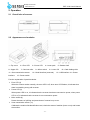
2.1 Overall size of scanner
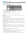
2.2 Appearance and modules
1—Top cover
2—Error LED
6—Upper CIS
7—Card out roller
11—Scan transmissive sensor
interface
3—Power LED
4—Lower path
8—Micro switch
5—Bottom shell
9—Lower CIS
12—Serial interface (reserved)
10—Card feeding roller
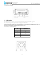
13—USB interface 14—Power
15—Power switch
Function explanation of partial modules:
¾
Error LED (2)
When the scanner works normally, the error LED is off; when error LED flashes, it indicates that
there is something wrong with scanner.
¾
Power LED (3)
When power LED is on, it indicates that the scanner has been connected to power; when power
LED is off, it indicates that the scanner is not connected to power.
¾
Micro switch (8)
Detect the status of uplifting and press-down of scanner’s top cover.
¾
Scan transmissive sensor (11)
Calibrate the medium like identification card, check the status of medium (have or not) and locate
the medium.
-3-