1
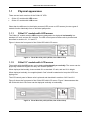
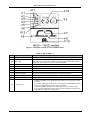
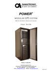
G-NET 1, 2, 3, 6 AND 10 KVA 19” UPS SYSTEMS USER GUIDE Release 1.3, January 2014 GAMATRONIC ELECTRONIC INDUSTRIES LTD. 17 HARTOM ST., PO BOX 45029, JERUSALEM 91450, ISRAEL TEL: +972-2-588-8222 FAX: +972-2-582-8875 EMAIL: [email protected] WEBSITE: WWW.GAMATRONIC.COM Gamatronic Electronic Industries Ltd. Har Hotzvim Industrial Park 17 Hartom St., PO Box 45029, Jerusalem 91450 Israel Tel: +972-2-588-8222 Fax: +972-2-582-8875 Email: [email protected] Website: www.gamatronic.com The equipment described in this document is not intended to be used in connection with any application requiring fail-safe performance, unless the application design includes appropriate redundancy. This exclusion includes, but is not limited to, the direct operation of any life support system or any other system whose failure could lead to serious injury, death, environmental damage or mass destruction. Copyright 2014 by Gamatronic Electronic Industries Ltd. All rights reserved worldwide. Any representations in this document concerning the performance of Gamatronic's product(s) are for informational purposes only and are not warranties of future performance, either express or implied. Gamatronic's standard limited Warranty, which accompanies its sales contract or order confirmation form, is the only warranty offered by Gamatronic Electronic Industries Ltd. in relation thereto. Gamatronic Electronic Industries Ltd. ("Gamatronic") warrants the products it manufactures to be free from defect for a period of one calendar year from the date of invoice, including the date of invoice. Gamatronic's liability is limited to repairing or replacing any defective parts in the equipment under warranty. Gamatronic reserves the right to determine whether the repair work shall be performed at Gamatronic's factory, at the customer's premises, or at an alternate site. The customer must obtain authorization from Gamatronic before returning any parts or equipment to Gamatronic for repair or replacement. Any items returned to Gamatronic must be sent freight prepaid. Gamatronic’s liability and warranty to the product are according and subject to the fulfillment and implementation by the customer of all the terms and instructions in connection with “preventive maintenance” and “service and repair” as further detailed in the user guide which is attached to the product and forms an integral part of it.” Gamatronic is not responsible for any damage to the product due to unauthorized repair work, misuse or abuse of the product, or force majeure. If the product is delivered without batteries, Gamatronic is not responsible for any damage or malfunction due to incorrect wiring of the batteries. Gamatronic is not liable for and the Purchaser waives any right of action it has or may have against Gamatronic for any consequential or special damages arising out of any breach of warranty, and for any damages that the Purchaser may claim for damage to any property or injury or death to any person arising out of its purchase or the use, operation or maintenance of the subject product. This warranty includes parts and labor; however, Gamatronic shall not be responsible for any labor subcontracted or performed by the Purchaser to prepare the warranted item for return to Gamatronic or Gamatronic's agent. The information contained in this document is proprietary and is subject to all relevant copyright, patent and other laws protecting intellectual property, as well as any specific agreement protecting Gamatronic's rights in the aforesaid information. Neither this document nor the information contained herein may be published, reproduced or disclosed to third parties, in whole or in part, without the express, prior, written permission of Gamatronic. In addition, any use of this document or the information contained herein for any purposes other than those for which it was disclosed is strictly forbidden. Gamatronic reserves the right, without prior notice or liability, to make changes in equipment design or specifications. Information supplied by Gamatronic is believed to be accurate and reliable. However, no responsibility is assumed by Gamatronic for the use thereof nor for the rights of third parties which may be affected in any way by the use thereof. This document may contain flaws, omissions or typesetting errors; no warranty is granted nor liability assumed in relation thereto unless specifically undertaken in Gamatronic Electronic Industries Ltd. standard limited Warranty. Information contained herein is periodically updated and changes will be incorporated into subsequent editions. If you have encountered an error, please notify Gamatronic Electronic Industries Ltd. All specifications are subject to change without prior notice. ii G-Net 1 to 10 kVA 19” UPS systems Gamatronic Electronic Industries Ltd. TABLE OF CONTENTS 1. INTRODUCTION .................................................................................................................................. 1 1.1 Physical appearance ........................................................................................................ 2 1.1.1 G-Net 19” models with LED screen ........................................................................ 2 1.1.2 G-Net 19” models with LCD screen........................................................................ 2 1.2 Technical specifications .................................................................................................. 5 2. UNPACKING AND INSTALLATION ......................................................................................................... 6 2.1 Unpacking and Inspection ............................................................................................... 6 2.2 Before installation ............................................................................................................ 6 2.3 Installation (for 1, 2, and 3 kVA models) ........................................................................ 7 2.4 Installation (for 6 and 10 kVA models) ........................................................................... 8 3. FRONT PANEL OF THE UPS ................................................................................................................ 9 3.1 Models with LED display ................................................................................................. 9 3.2 Load level indicator on LED display ............................................................................. 11 3.3 Battery level indicator on LED display ......................................................................... 11 3.4 Models with LCD display ............................................................................................... 12 3.5 Load level indicator on LCD display............................................................................. 13 3.6 Battery level indicator on LCD display ......................................................................... 13 4. OPERATING THE G-NET UPS........................................................................................................... 14 4.1 Basic operations ............................................................................................................. 14 4.1.1 Starting the UPS ................................................................................................... 14 4.1.2 Shutting down the UPS (from inverter mode)....................................................... 14 4.1.3 Shutting down the UPS (from battery mode)........................................................ 14 4.1.4 Starting the UPS in battery mode (cold-starting) .................................................. 14 4.2 Operation modes ............................................................................................................ 15 4.2.1 Inverter mode (normal or main mode) .................................................................. 15 4.2.1.1 4.2.1.2 Inverter mode on the LED display ...................................................................... 15 Inverter mode on the LCD display...................................................................... 15 4.3 Battery mode ................................................................................................................... 16 4.3.1 Battery mode on the LED display ......................................................................... 16 4.3.2 Battery mode on the LCD display ......................................................................... 16 4.3.3 Testing battery mode ............................................................................................ 16 4.4 Bypass mode .................................................................................................................. 17 4.4.1 Bypass mode on the LED display ........................................................................ 17 4.4.2 Bypass mode on the LCD display ........................................................................ 17 5. COMMUNICATION............................................................................................................................. 18 6. BATTERY MAINTENANCE .................................................................................................................. 18 7. TROUBLESHOOTING ........................................................................................................................ 19 7.1 Troubleshooting for models with LED display ............................................................ 19 7.2 Troubleshooting for models with LCD display ........................................................... 21 8. PREVENTIVE MAINTENANCE ............................................................................................................. 22 9. SERVICE AND REPAIRS .................................................................................................................... 22 G-Net 1 to 10 kVA 19” UPS systems iii GAMATRONIC ELECTRONIC INDUSTRIES LTD. Figure 1: Figure 2: Figure 3: Figure 4: Figure 5: Figure 6: Figure 7: Figure 8: TABLE OF FIGURES The G-Net front panel (10 kVA, with LED screenl) ............................................................... 2 The G-Net front panel (10 kVA, with LCD screenl) ............................................................... 2 The G-Net 19” model with LCD screen, horizontal and vertical deployments ...................... 3 Rear panel of G-Net 1 – 3 kVA 19” models .......................................................................... 4 Rear panel of G-Net 6 and 10 kVA 19” models .................................................................... 4 LED-type screens of 1, 2, and 3 kVA models ....................................................................... 9 LED-type screens of 6 and 10 kVA models ........................................................................ 10 Front panel of the G-Net UPS models with LCD display .................................................... 12 LIST OF TABLES Table 1: Technical specifications for G-Net 19” UPS models .............................................................. 5 Table 2: Battery pack specifications ..................................................................................................... 5 Table 3: Derating factors ...................................................................................................................... 5 Table 4: Key to Figure 6 ....................................................................................................................... 9 Table 5: Key to Figure 7 ..................................................................................................................... 10 Table 6: The LED column as a load-level indicator ............................................................................ 11 Table 7: The LED column as a battery-charge indicator.................................................................... 11 Table 8: Key to Figure 8 ..................................................................................................................... 12 Table 9: Interpreting the indicators on the LED display ..................................................................... 20 iv G-Net 1 to 10 kVA 19” UPS systems GAMATRONIC ELECTRONIC INDUSTRIES LTD. STANDARDS AND CONVENTIONS This user manual contains diagrams which include images of the display screen of the UPS. Unless otherwise indicated, the readings shown in the screen images are representational only, and are not intended to match the readings on a specific system in a particular environment. G-Net 1 to 10 kVA 19” UPS systems v GAMATRONIC ELECTRONIC INDUSTRIES LTD. SAFETY CONSIDERATIONS The G-Net UPS system should be handled with appropriate care, following these guidelines. Do’s • Read this manual carefully before starting installation and operation of the UPS. • Review the safety precautions described below to avoid injury to users or damaging equipment. • All power connections must be completed by a licensed electrician who is experienced in wiring this type of equipment, and who is knowledgeable about national and local electrical codes and regulations. Improper wiring may cause injury to personnel, or death, or damage to the equipment. • Pay attention to the warning signs, labels and marks on the unit. A warning sign signals the presence of a possibly serious, life-threatening condition. • Keep the surroundings clean, uncluttered and free from excess moisture. • Allow only qualified technicians to service the UPS. There are no user-serviceable components. Do not try to repair it yourself! • Use the UPS only for its intended purpose. • The batteries should be installed next to the UPS, or as close to it as is practically possible. WARNING - RISK OF LETHAL ELECTRIC SHOCK: The battery cabinet contains a series of 12-Volt batteries that provide high voltage and energy in the UPS body even when the UPS is not connected to the ac input. Take appropriate precautions during installation, inspection and servicing. vi G-Net 1 to 10 kVA 19” UPS systems GAMATRONIC ELECTRONIC INDUSTRIES LTD. Don’ts • Do not open the cover of the UPS or the battery cabinets under any circumstances. • Do not insert any objects through the ventilation holes. • Do not rest objects on the UPS. • Do not move the UPS while it is operating. • Do not use the UPS outdoors. • Do not turn the UPS upside down during transportation. • Do not connect or disconnect the cable to the battery cabinet before the battery circuit breaker is turned OFF. • Do not turn ON the battery circuit breaker when the battery cabinet is disconnected from the UPS. • Do not install the UPS next to gas or electrical heaters. A restricted location is recommended in order to prevent access by unauthorized personnel. G-Net 1 to 10 kVA 19” UPS systems vii GAMATRONIC ELECTRONIC INDUSTRIES LTD. This page left blank deliberately. viii G-Net 1 to 10 kVA 19” UPS systems GAMATRONIC ELECTRONIC INDUSTRIES LTD. 1. INTRODUCTION The G-Net is an advanced, true online Uninterruptible Power Supplies (UPSs) providing reliable, regulated and stable voltage to any type of load, from computers and telecommunication systems to automated industrial control systems. The G-Net 19” UPS is available in models for loads of 1, 2, 3, 6 and 10 kVA. In general, an Uninterruptible Power Supply (UPS) provides backup power for use when the utility ac electric power mains fail or drop to an unacceptable voltage level. G-Net does this and more. Voltage surges, spikes and sags are inherent in commercial utility power. Over time, these irregularities shorten the life of equipment and components. The G-Net UPS continually eliminates power irregularities, thus helping to extend the life of your equipment, even through normal use when the input power is constant and continuous. G-Net requires very little attention or intervention during normal operation; however, you should read and understand the procedures described in this manual to ensure trouble-free operation. G-Net 1 to 10 kVA 19” UPS systems 1 GAMATRONIC ELECTRONIC INDUSTRIES LTD. 1.1 Physical appearance There are two basic versions of the G-Net 19” UPS: • G-Net 19” models with LED screen • G-Net 19” models with LCD screen Other than the difference in the display screens (LED screen vs LCD screen), the two types of models function identically from an electrical perspective. 1.1.1 G-Net 19” models with LED screen The G-Net 19” models with the LED screen are designed to be deployed horizontally in a standard 19” rack, and are 2U in height. The LED control panel of these units is pictured and described in sections 3.1, 3.2 and 3.3. Figure 1 shows the front panel of the G-Net UPS with LCD screen. Figure 1: The G-Net front panel (10 kVA, with LED screenl) 1.1.2 G-Net 19” models with LCD screen The models with the LCD screen can be deployed horizontally or vertically. The screen can be physically rotated 90 degrees for easy use in either position. When deployed horizontally, these models fit in a standard 19” rack, and are 2U in height. When deployed vertically, the supplied plastic “feet” should be attached to keep the UPS from tipping over. The LCD control panel of these units is pictured and described in sections 3.43.5 and 3.6. Figure 2 shows the front panel of the G-Net UPS with LCD screen. Figure 3 demonstrates that the G-Net with the LCD screen can be deployed vertically or horizontally. Figure 2: The G-Net front panel (10 kVA, with LCD screenl) 2 G-Net 1 to 10 kVA 19” UPS systems GAMATRONIC ELECTRONIC INDUSTRIES LTD. Figure 3: The G-Net 19” model with LCD screen, horizontal and vertical deployments G-Net 1 to 10 kVA 19” UPS systems 3 GAMATRONIC ELECTRONIC INDUSTRIES LTD. Figure 4: Rear panel of G-Net 1 – 3 kVA 19” models Figure 5: Rear panel of G-Net 6 and 10 kVA 19” models 4 G-Net 1 to 10 kVA 19” UPS systems GAMATRONIC ELECTRONIC INDUSTRIES LTD. 1.2 Technical specifications Table 1: Technical specifications for G-Net 19” UPS models G-NET TECHNICAL SPECIFICATIONS 1 KVA 2 KVA 3 KVA 6 KVA Topology Operation Input Voltage (Vac) 10 KVA True on-line, double-conversion, VFI Continuous 145~285, single phase Current, max. (A) Frequency (Hz) Power factor (full load) Output Rated power (kVA / kW) Frequency (Hz, battery mode) Voltage (Vac) Current (A) 105 % ~ 125 % Overload 125 % ~ 135 % >135 % Waveform Linear load THD (full load) Non-linear load Load CF (max) Power factor Batteries (see also Table 2) Type Dc voltage (Vdc), ampere/hours Backup time General Ambient temperature (°C) Relative humidity (%) Altitude (m) Cooling system Standards Safety EMC Design Low magnetic field radiation Weights and dimensions UPS wgt (kg) UPS dimensions (H x W x D, mm) * with internal batteries 7 12 0.96 1 / 0.8 5.4 120~276, single phase 16 50/60 ±5 % 31 0.98 2 / 1.6 3 / 2.4 6 / 4.8 10 / 8 50/60 ±0.5 % 50/60 ±0.2 % 220/230 ±1 %, single-phase 9.6 13 27 45 10 min. to bypass after 1 min. 1 min. to bypass after 30 sec. 200 ms to bypass after 100 ms Sinusoidal ≤3 % ≤6 % 3:1 0.8 Sealed, lead acid, rechargeable, maintenance-free 36 V, 7 Ah 96 V, 7 Ah 192 V, 9 Ah 10 ~ 15 min (typical) 0 ~ 40 (operation and storage) 20 ~ 90 (non-condensing) 1000 without derating (derating table below) Forced air (multi-fan with speed control) IEC 62040-1 IEC 62040-2 IEC 62040-3 EMF as per ICNIRP 7.5 (13 *) 13 88 x 430 x 480 14 33 Table 2: Battery pack specifications MODEL 96 V battery pack 192 V battery pack 50 NUMBER AND TYPE OF BATTERIES 8 x 12 V, 7 Ah 16 x 12 V, 9 Ah CABINET DIMENSIONS (HXWXD, MM) 88 x 430 x 480 88 x 430 x 680 88 x 430 x 680 35 WEIGHT (KG) 18 52 Table 3: Derating factors Altitude (m) Derating factor 1000 100 % OUTPUT DERATING FACTOR FOR HIGHER ALTITUDES 1500 2000 2500 3000 3500 95 % 91 % 86 % 82 % 78 % 4000 74 % 4500 70 % 5000 67 % All specifications are subject to change without advance notice. G-Net 1 to 10 kVA 19” UPS systems 5 GAMATRONIC ELECTRONIC INDUSTRIES LTD. UNPACKING AND INSTALLATION 2. 2.1 1. Unpacking and Inspection Open the package and veryify that in addition to the UPS itself, the following accessories are present: • • • • • 2. 2.2 This user guide (may be on a CD). Mains-to-UPS power cable. Monitor software (on CD) and UPS-to-computer communication cable. Battery cable (except for 1K UPS model). “Feet” for the UPS, when installed in a vertical position. Verify that the UPS has not been damaged in transit. If you note any damage, do not start up the UPS, and inform your dealer of the problem. Before installation 1. The UPS should be installed in a location that is well-ventilated, dry, and free from combustible gas and corrosive materials. 2. Ensure that the UPS’s ventilation holes are not obstructed. 3. Environmental temperature should be between 0 and 40 °C. 4. If the UPS is being unpacked in a location with low temperature, beware of the possibility of condensation. In such a case, to avoid electric shock, do not install or use the UPS until the inside and outside of the UPS is completely dry. 6 G-Net 1 to 10 kVA 19” UPS systems GAMATRONIC ELECTRONIC INDUSTRIES LTD. 2.3 1. Installation (for 1, 2, and 3 kVA models) If you have received a battery box, connect the battery to the UPS as follows: 1.1 Verify that the batteries are connected in series. 1.2 Verify that the battery voltage is appropriate for the UPS model. UPS MODEL Voltage (Vdc) 1.3 1 KVA 36 2 KVA 96 3 KVA 96 Use the supplied cable to connect the battery box with the rear panel of the G-Net. 2. Use the supplied cable to connect the UPS to the ac power mains socket that is grounded. The connection on the UPS for this cable is located on the rear panel and is labeled INPUT. See Figure 4. 3. After connection to the mains, you will here the UPS’s fan operating. On models with the LCD display (see chapter 3), the bar graph on the front panel indicates the state of the battery at all times – the more LEDs lit in the bar graph, the higher the battery’s present charge level. On models with the LED display (see chapter 3), the bar graph indicates the battery charge level only when the UPS is in battery mode. You can put the UPS in battery mode temporarily by disconnecting the ac input line when the UPS is “ON”. The bar graph will then indicate the battery charge level. Important notice: The UPS is delivered with the batteries uncharged. The batteries are not able to provide backup power of normal duration until they have been charged. To charge the UPS batteries, leave the UPS connected to the ac mains in the “OFF” state with no load devices attached to the UPS, for at least 8 hours. It is permissible to use the UPS before the 8 hours of charging is complete. Just be aware that if you do so, the duration of backup power (in the event of a power failure) will be shorter than normal until the battery charging process has completed. 4. To switch the UPS “ON”, press the ON button on the front panel of the UPS. 5. Before connecting a load or loads to the UPS, make sure that the load is “OFF”. After connecting the loads, start them up one-by-one. 6. In the ON state, in inverter or bypass mode (not in battery mode) the LED bar graph on the front panel indicates the load level relative to the UPS’s maximum capacity. 7. Laser printers draw a lot of current. If you intend to use the UPS to back-up a laser printer, be sure that the UPS output power is greater than or equal to the startup power of the printer. G-Net 1 to 10 kVA 19” UPS systems 7 GAMATRONIC ELECTRONIC INDUSTRIES LTD. 2.4 Installation (for 6 and 10 kVA models) 1. Verify that the circuit breaker on the UPS rear panel is in the “OFF” position. 2. Connect the battery to the UPS as follows: 2.1 Verify that the batteries are connected in series. 2.2 Verify that the battery voltage is appropriate for the UPS model. UPS MODEL Voltage (Vdc) 2.3 6 KVA 192 10 KVA 192 Connect the battery cable to the battery box first. There are three wires to be connected: “+”, “–“, and Ground. Then connect the other end of the cable to the UPS. 3. Connect the power cable to the UPS and plug it into an ac mains socket that is grounded and that is protected with an over-current protection device (fuse or circuit breaker). 4. Switch ON the circuit breaker on the rear of the UPS. After a few seconds the UPS will indicate on the front panel that it is in bypass mode. 5. If this is the first time that the batteries are being used, it is recommended that you leave the UPS in this state for eight hours (without attaching a load) to charge the battery. If you don’t do this, you can still use the UPS, but the backup-time provided by the battery will be less than normal until it has become fully charged. 6. Before connecting a load or loads to the UPS, make sure that the load is “OFF”. After connecting the loads, start them up one-by-one. 7. Laser printers draw a lot of current. If you intend to use the UPS to back-up a laser printer, be sure that the UPS output power is greater than or equal to the startup power of the printer. 8 G-Net 1 to 10 kVA 19” UPS systems GAMATRONIC ELECTRONIC INDUSTRIES LTD. FRONT PANEL OF THE UPS 3. 3.1 Models with LED display Figure 6: LED-type screens of 1, 2, and 3 kVA models Table 4: Key to Figure 6 ITEM NAME DESCRIPTION Malfunction indicator When lit (red), indicates a UPS malfunction. See section 7, Troubleshooting. Bar graph These 5 LEDs form a bar graph. In normal and bypass modes the bar graph represents the UPS load level. In battery mode the bar graph represents the battery charge level. See sections 3.2 and 3.3 for more information. 7 Bypass indicator Lights (orange) when the system is in bypass mode. 8 Ac input indicator Lights (green) when the ac input voltage is normal. 9 Inverter indicator Lights (green) when the inverter is providing power to the loads. 10 Battery indicator Lights (orange) when the UPS is providing power to the loads from the battery. 1 2-6 • On 1~3 kVA models, this is the ON key. Press for one seconds to switch the UPS “ON”, press for one second to switch the UPS “OFF”. 11 ON key and alarm mute • In battery mode, pressing this key for 3 seconds mutes the audible alarm. Pressing this key for another 3 seconds returns the audible alarm to normal mode. • In inverter (normal) mode, pressing the ON key performs a battery test. 12 OFF key G-Net 1 to 10 kVA 19” UPS systems Press and hold to turn the UPS “OFF”. 9 GAMATRONIC ELECTRONIC INDUSTRIES LTD. Figure 7: LED-type screens of 6 and 10 kVA models Table 5: Key to Figure 7 ITEM NAME DESCRIPTION Malfunction indicator When lit (red), indicates a UPS malfunction. See section 7, Troubleshooting. Bar graph These 5 LEDs form a bar graph. In normal and bypass modes the bar graph represents the UPS load level. In battery mode the bar graph represents the battery charge level. See sections 3.2 and 3.3 for more information. 7 Bypass indicator Lights (orange) when the system is in bypass mode. 8 Ac input indicator Lights (green) when the ac input voltage is normal. 9 Inverter indicator Lights (green) when the inverter is providing power to the loads. 10 Battery indicator Lights (orange) when the UPS is providing power to the loads from the battery. 11 Load level graphic This scale is for when LEDs #6 through #2 are a load level bar graph. 12 Battery level graphic This scale is for when LEDs #2 through #6 are a battery charge level bar graph. 13 ON/OFF key On 6 kVA and 10 kVA models, this key is the ON/OFF button. 1 2-6 14 10 “Function key” • In bypass or battery mode, pressing this key for 2 to 10 seconds mutes the alarm of bypass and battery mode. Pressing the key again for 2 to 10 seconds restores the alarm. • In any mode, pressing the function key for more than 10 seconds mutes the alarm of all modes. Repeating the process un-mutes the alarm. • To perform a battery test, press the Function key for 2 to 10 seconds in main mode. The battery test lasts for about 30 seconds, during which the charge level of the battery is displayed on the bar graph. G-Net 1 to 10 kVA 19” UPS systems GAMATRONIC ELECTRONIC INDUSTRIES LTD. 3.2 Load level indicator on LED display When the UPS is operating in inverter mode (normal mode) the column of five LEDs (4 green and 1 orange) serves as a load-level indicator. Table 6 explains how to interpret the LEDs in this situation. Table 6: The LED column as a load-level indicator LEDS LIT * RELATIVE LOAD LEVEL 6 0–30 % 65 31–50 % 654 51–70 % 6543 71–95 % 65432 96 %+ (overload) COMMENT The audible alarm beeps twice per second. Turn off unnecessary load devices. * According to the LED numbering used in Figure 6 and Figure 7. 3.3 Battery level indicator on LED display When the UPS is operating in battery mode – that is, there is no ac input to the UPS and it is supplying power to the load from the battery – the audible alarm beeps about once every four seconds and the column of five LEDs (4 green and 1 orange) serves as a battery-level indicator, showing the relative amount of electrical energy remaining in the battery. Table 7 below explains how to interpret the column of 5 LEDs in such a situation. Table 7: The LED column as a battery-charge indicator. LEDS LIT * RELATIVE LOAD LEVEL COMMENT 65432 100 % Battery is fully charged. Alarm beeps once every four seconds. 6543 76–99 % Alarm beeps once every four seconds. 654 51–75 % Alarm beeps once every four seconds. 65 26–50 % Alarm beeps once every four seconds. 6 0–25 % The battery is almost exhausted. The audible alarm beeps once per second. * According to the LED numbering used in Figure 6 and Figure 7. G-Net 1 to 10 kVA 19” UPS systems 11 GAMATRONIC ELECTRONIC INDUSTRIES LTD. 3.4 Models with LCD display Figure 8: Front panel of the G-Net UPS models with LCD display Table 8: Key to Figure 8 ITEM NAME DESCRIPTION 1 Input frequency indicator Displays the frequency of the ac input. 2 Alarm or malfunction indicator When displayed, this triangle-shaped symbol indicates an alarm condition or a UPS malfunction. 3 Alarm not muted This indicator is displayed when the audible alarm is not muted (is normal). 4 Input voltage The highest number displayed in this column indicates the input voltage. 5 Battery level bar graph This column contains a bar graph that indicates the battery charge level. 6 Load level bar graph 7 Output voltage The more blocks displayed, the greater the battery charge level, in accordance with the percentages to the right of the bar graph. This column contains a bar graph that indicates the load level on the UPS as a percentage of the UPS’s maximum capacity. The more blocks displayed, the greater the load on the UPS, in accordance with the percentages to the left of the bar graph. The highest number displayed in this column indicates the UPS’s output voltage. • On 1~3 kVA models, this is the ON key. Press and hold to switch the UPS on, press and hold to switch the UPS off. 8 1 ~ 3 kVA models: ON key and alarm mute • In normal (inverter) mode, pressing this key initiates a battery test, which lasts about 30 seconds. 6 ~ 10 kVA models: ON/OFF key 9 10 12 • In bypass or battery mode, pressing this key mutes the audible alarm. Pressing this key again returns the audible alarm to normal mode. Mode indicator 1 ~ 3 kVA models: OFF key 6 ~ 10 kVA models: “Function key” On 6 and 10 kVA models, this key is the ON/OFF key Indicates whether the UPS is in inverter (normal) mode, bypass mode, or battery mode. Press and hold to turn the UPS “OFF”. Mutes /unmutes the audible alarm. G-Net 1 to 10 kVA 19” UPS systems GAMATRONIC ELECTRONIC INDUSTRIES LTD. 3.5 Load level indicator on LCD display When the UPS is operating in inverter mode (normal mode) the column of six rectangles under the balance symbol serves as a bar graph to indicate the load level on the UPS, as a percentage of the UPS’s maximum capacity, according to the numbers to the left of the bar graph. 3.6 Battery level indicator on LCD display When the UPS is operating in battery mode, there is no ac input to the UPS and it is supplying power to the load from the battery. The audible alarm beeps about once every four seconds. The column of six rectangles under the battery symbol is a bar graph showing the relative amount of electrical energy remaining in the battery, according to the numbers to the right of the bar graph. When the battery is almost fully discharged (0 – 25 %), the speed of the audible alarm increases to one beep per second. G-Net 1 to 10 kVA 19” UPS systems 13 GAMATRONIC ELECTRONIC INDUSTRIES LTD. OPERATING THE G-NET UPS 4. 4.1 Basic operations 4.1.1 Starting the UPS 1. For models that use an external battery, verify that the battery is connected to the UPS. 2. Verify that the UPS is connected to the ac mains. 3. For models with an input circuit breaker on the rear panel (6 kVA and 10 kVA models), move the circuit breaker to the “ON” position. 4. On the front panel of the UPS, press the “ON” button for about 2 seconds. The UPS will run in bypass mode for a few seconds while it performs a self-test, after which it moves automatically to inverter (normal) mode. 4.1.2 Shutting down the UPS (from inverter mode) 1. Press the “OFF” button for about 2 seconds. 2. The UPS moves to bypass mode and performs a self-test, after which it continues to provide power in bypass mode. 3. To stop all UPS output: • • 4.1.3 for 6 and 10 kVA models, switch OFF the circuit breaker on the UPS rear panel; for 1, 2 and 3 kVA models, shut down the loads and then disconnect the UPS from the ac mains. Shutting down the UPS (from battery mode) 1. Press the “OFF” button for about 2 seconds. 2. The UPS performs a self-test for a few seconds and then shuts off. There is no further output from the UPS. 4.1.4 Starting the UPS in battery mode (cold-starting) If there is no ac input supply to the UPS, it can still be started in battery mode. Press the ON button for about 2 seconds to start the UPS in battery mode. 14 G-Net 1 to 10 kVA 19” UPS systems GAMATRONIC ELECTRONIC INDUSTRIES LTD. 4.2 Operation modes The G-Net UPS has three main modes of operation: • Inverter mode (normal or main mode). • Battery mode. • Bypass mode. 4.2.1 4.2.1.1 Inverter mode (normal or main mode) Inverter mode on the LED display In inverter mode on models with the LED display: • The ac input LED and the inverter LED are lit. • The bar graph indicates the UPS’s load level. • When the battery indicator lights and the ac input indicator flashes, it means the UPS has moved into battery mode because the voltage or frequency of the ac input is out of range. • When the load on the ups is greater than 105 % of rated capacity, the audible alarm beeps twice per second. In such a case, you must reduce the load on the UPS to below 90 %. This will cause the alarm to stop beeping. 4.2.1.2 Inverter mode on the LCD display • The Line and Inverter symbols are displayed at the bottom of the screen. • The voltage and frequency of the ac input are displayed. G-Net 1 to 10 kVA 19” UPS systems 15 GAMATRONIC ELECTRONIC INDUSTRIES LTD. 4.3 Battery mode 4.3.1 Battery mode on the LED display When the UPS is in battery mode, the battery indicator and the inverter indicator light. If the ac input voltage is present but abnormal, the ac input indicator flashes. The bar graph indicates the state of the battery. The number of lit LEDs in the bar graph decreases as the battery discharges. In battery mode, the audible alarm beeps once every four seconds. The alarm can be silenced by pressing the “ON/alarm mute” button (or the Function key on 6 and 10 kVA models) for about two seconds. To restart the alarm, press the button again for about two seconds. When the battery is almost fully discharged (0 – 25 %), the speed of the audible alarm increases to one beep per second. When the battery is fully discharged the UPS shuts off. 4.3.2 Battery mode on the LCD display When the UPS is in battery mode, the battery indicator and the inverter indicator are seen at the bottom of the screen. The battery graph indicates the state of the battery. The number of lit rectangles in the bar graph decreases as the battery discharges. In battery mode, the audible alarm beeps once every four seconds. The alarm can be silenced by pressing the “ON/alarm mute” button (or the Function key on 6 and 10 kVA models) for about two seconds. To restart the alarm, press the button again for about two seconds. When the battery is almost fully discharged (0 – 25 %), the speed of the audible alarm increases to one beep per second. When the battery is fully discharged the UPS shuts off. 4.3.3 Testing battery mode Battery (backup) mode can be tested by momentarily disconnecting the UPS from the ac input. 16 G-Net 1 to 10 kVA 19” UPS systems GAMATRONIC ELECTRONIC INDUSTRIES LTD. 4.4 Bypass mode 4.4.1 Bypass mode on the LED display In bypass mode, the bypass indicator lights green and the inverter indicator is not lit. The ac input indicator is also lit. If it flashes, it means that the voltage or frequency of the ac input power is out of range. In bypass mode, the load level bar graph functions as usual, and the audible alarm sounds once every two minutes. During bypass operation, the load receives power directly from the ac mains. Whenever the inverter cannot provide power to the load, either due to an overload or a short-circuit in the load, the UPS automatically moves to bypass mode. When the problem is corrected, the load is automatically transferred back to the inverter. Note: in bypass mode, there is no backup function. 4.4.2 Bypass mode on the LCD display In bypass mode, the line and bypass indicator are displayed at the bottom of the screen. The battery and inverter indicators are not displayed. In bypass mode, the load level bar graph functions as usual, and the audible alarm sounds once every two minutes. During bypass operation, the load receives power directly from the ac mains. The UPS goes into bypass mode automatically whenever the inverter cannot provide power to the load, either due to an overload or a short-circuit in the load,. When the problem is corrected, the load is automatically transferred back to the inverter. Note: in bypass mode, there is no backup function. G-Net 1 to 10 kVA 19” UPS systems 17 GAMATRONIC ELECTRONIC INDUSTRIES LTD. 5. COMMUNICATION The UPS has an RS232 interface for serial communication between the UPS and a computer. The RS232 connection is a female D9 connection on the UPS’s rear panel. Transmission characteristics are: • 2400 bps • 8 data bits • no parity bit • 1 stop bit. PIN NUMBER FUNCTION DESCRIPTION 2 Txd Output 3 Rxd Input 5 GND Ground 6. BATTERY MAINTENANCE Keeping the battery charged helps you achieve maximum battery lifetime. Normal useful battery life is three to five years, but this depends on the ambient temperature and number of charge-discharge cycles the battery undergoes. Optimal temperature for achieving maximum battery lifetime is 20 °C. It is recommended that the UPS battery be discharged and recharged once every four to six months. The recharge time should be at least 12 hours. This applies to a UPS in regular service, and to a UPS that is not in use for an extended period of time. If the battery is not holding a charge, it may be time to replace it. Replacement of the battery should be performed by a professional. Batteries should be replaced with batteries of the same type and rating. 18 G-Net 1 to 10 kVA 19” UPS systems GAMATRONIC ELECTRONIC INDUSTRIES LTD. 7. TROUBLESHOOTING In the event that the malfunction indicator lights up and the audible alarm sounds, use this table to diagnose the problem. 7.1 Troubleshooting for models with LED display Use the table below, referencing Figure 6 or Figure 7 for the numbers of the LEDs. SYMPTOM REASON SUGGESTED ACTION Indicators 1 and 6 are lit and the alarm beeps continuously Over-temperature The UPS may be overloaded, and/or the room temperature may be very high. Turn off the UPS for 10 minutes to let it cool down. Reduce the load on the UPS. Try to restart the UPS. If the condition persists, contact your distributor. Indicators 1 and 5 are lit and the alarm beeps continuously There is a short circuit, probably in one of the loads. Disconnect all loads and verify that none of them are shortcircuited. Turn on the UPS again, with no loads. If the UPS still indicates the presence of a short circuit, contact your distributor. Indicators 1 and 4 are lit and the alarm beeps continuously UPS internal fault. Contact your distributor. Indicators 1 and 3 are lit and the alarm beeps continuously The UPS is protecting the battery from over-charging. There is a problem with the charger. Contact your distributor. The ac input indicator flashes The voltage or frequency of the ac power mains is out of range. Determine the reason for the irregular ac supply. Indicators 1 and 2 are lit and the alarm beeps continuously The UPS is overloaded. Disconnect nonessential loads from the UPS. The battery indicator flashes Battery voltage is low, or the battery is not connected to the UPS. Verify that the battery cables are firmly connected on the battery side and on the UPS side. Measure the battery voltage. Indicator 1 is lit and the battery indicator flashes Charger fault. Please contact your distributor. Ac input power is normal but the UPS does not go into inverter mode The UPS’s ac input circuit breaker may be open. On the UPS’s rear panel, push the circuit breaker to reset it. The battery was discharged recently and not enough time has passed for it to recharge fully. Connect the UPS to the ac mains and let it charge for at least 3 hours with no loads attached. It may be that the batteries are old and need replacing. Contact your distributor to replace the batteries. You are not pressing the button long enough. Press the ON button for at least 2 seconds. The UPS is not connected to the battery. Check the connections between the battery and the UPS. There is an electrical problem with the UPS. Please contact your distributor. The batteries discharge too quickly The UPS does not switch ON when the ON button is pressed. G-Net 1 to 10 kVA 19” UPS systems 19 GAMATRONIC ELECTRONIC INDUSTRIES LTD. Table 9: Interpreting the indicators on the LED display INDICATOR DISPLAY OPERATION STATUS #1 #2 #3 #4 #5 #6 #7 #8 #9 LINE NO. 1 2 3 4 5 6 7 8 9 10 11 12 13 14 15 16 17 18 19 20 21 22 23 24 25 26 27 28 29 30 31 32 33 34 35 36 37 38 39 40 41 42 43 44 45 Ac input mode (inverter or bypass mode) Battery mode Bypass mode Overload in inverter mode, no bypass Overload in inverter mode, went to bypass Ac input abnormal Bypass input abnormal Overload in battery mode, alarm Overload in battery mode, shutdown Over temperature Inverter abnormal Output short circuit Abnormal bus voltage Charger or battery fault Fan fault Parallel operation fault ID repetition Battery not connected Low battery voltage Phase and neutral reversed in ac input mode Battery failure EPO function Battery self-test mode Invalid UPS module Frequency converter mode ECO mode Read parameter wrong Rectifier failure or PFC failure Load failure Unequal current failure Power supply abnormal Inverter relay short circuit SCR failure in ac input mode Fuse blows in ac input mode Battery over-charged Support board abnormal Neutral line disconnected (in 3-phase input) Chart symbols: 20 0 – 35% load capacity 36-55% load capacity 56-75% load capacity 76-95% load capacity 96-105% load capacity 0-20% battery capacity 21-40% batt. capacity 41-60% batt. capacity 61-80% batt. capacity 81-100% batt. capacity = lit steadily ▲ ▲ ▲ ▲ ▲ ▲ ▲ ☼ = flashing ▲ ▲ ▲ ▲ ▲ ▲ ▲ ▲ ▲ ▲ ▲ ▲ ▲ ▲ ▲ ▲ ▲ ▲ ▲ ▲ ▲ ▲ ▲ ▲ ▲ ▲ ▲ ▲ ▲ ▲ ▲ ▲ ▲ ▲ ▲ ▲ ☼ ☼ ▲ ▲ ▲ ▲ ▲ ▲ ▲ ▲ ▲ ▲ ▲ ▲ ▲ ▲ ▲ ▲ ▲ ▲ ▲ ▲ ▲ ▲ ▲ ▲ ▲ ▲ ▲ ☼ ▲ ▲ ▲ ☼ ▲ ☼ ▲ ▲ ▲ ▲ ☼ ☼ ☼ ☼ Indicator LEDs cycle ▲ ▲ ▲ ▲ ☼ ▲ ☼ ▲ ▲ ▲ ▲ ▲ ▲ ▲ ▲ ▲ ▲ ▲ ▲ ▲ ▲ ▲ ▲ ▲ ▲ ▲ ☼ ☼ ▲ ▲ ▲ ▲ ▲ ☼ ▲ ▲ ▲ ▲ ▲ ▲ ▲ ▲ ▲ ▲ ▲ ▲ ▲ ▲ #10 AUDIBLE ALARM BEEPS none none none none none 1 per sec. 1 per 4 sec. 1 per 4 sec. 1 per 4 sec. 1 per 4 sec. 1 per 2 min. 2 per sec 2 per sec none 1 per 4 sec. 2 per sec continuous continuous continuous continuous 1 per sec 1 per sec continuous continuous 2 per sec 1 per sec continuous continuous 1 per sec continuous none continuous 1 per min 1 per min 1 per sec, only 3 x continuous continuous continuous continuous continuous continuous continuous continuous none 1 per 4 sec ▲ = State of indicator depends on other states. G-Net 1 to 10 kVA 19” UPS systems GAMATRONIC ELECTRONIC INDUSTRIES LTD. 7.2 Troubleshooting for models with LCD display SYMPTOM The UPS does not switch ON when the ON button is pressed. The batteries discharge too quickly REASON You are not pressing the button long enough. SUGGESTED ACTION Press the ON button for at least 2 seconds. The UPS is not Check the connections between the battery and connected to the battery. the UPS. There is an electrical problem with the UPS. Please contact your distributor. The battery was discharged recently and not enough time has passed for it to recharge fully. Connect the UPS to the ac mains and let it charge for at least 3 hours with no loads attached. It may be that the batteries are old and need replacing. Contact your distributor to replace the batteries. G-Net 1 to 10 kVA 19” UPS systems 21 GAMATRONIC ELECTRONIC INDUSTRIES LTD. 8. PREVENTIVE MAINTENANCE Every Gamatronic UPS contains technologically advanced electronic systems. These electronic systems are sensitive to environmental conditions. It is important that the operating and storage environments of the UPS be clean and dust-free, free of dampness and excess humidity. The system's batteries provide back-up power to the UPS when needed. An environmental temperature of 20 °C (68 °F) is ideal for the batteries. Significantly higher temperatures shorten the batteries' lifespan. The UPS and its batteries both require periodic preventive maintenance inspections. At the least, these inspections should include a visual inspection of the UPS and its batteries, and the tightening of any screws and bolts that have over time become loosened. The owner of the UPS is responsible for ensuring that the preventive maintenance inspections take place. This is done by contacting Gamatronic's service department and arranging a mutually convenient time for a technician to perform the inspection. It is important that the UPS owner continue to arrange regular preventive maintenance inspections even after the expiration of the initial warrantee period. Gamatronic bears no liability for damage caused to the UPS due to improper maintenance by third parties, in particular after the expiration of the warrantee or service agreement. It is the responsibility of the UPS owner to uphold his responsibilities according to the warrantee or service agreement. This includes ensuring that the UPS's environment meets requirements. 9. SERVICE AND REPAIRS Gamatronic maintains a team of service technicians, repair laboratories, and an ample inventory of spare parts, dedicated to the service and repair of our products. When service is required, it will be performed either at the customer's site or in one of our laboratories, according to the judgment of our technician and the specifics of the service agreement between the customer and Gamatronic. In regards to service, oral agreements have no standing. Service shall be provided gratis during the warrantee period, on the condition that the UPS has been properly maintained and a written record has been kept of any maintenance performed on the system. The initial warrantee period can be extended by a written service agreement between Gamatronic and the customer. Without a written agreement, Gamatronic is under no obligation to provide service after expiration of the initial warrantee period. Gamatronic will not be responsible for maintenance or changes to the UPS that are performed by an agent without written authorization from Gamatronic. 22 G-Net 1 to 10 kVA 19” UPS systems GAMATRONIC ELECTRONIC INDUSTRIES LTD. For a full company profile, please visit our website at www.gamatronic.com. Gamatronic Building, Jerusalem, Israel Gamatronic’s product range: UPS Systems Power systems for Telecom Dc-to-Ac Inverters Dc-to-Dc Converters Frequency Changers Battery Chargers Power Management Solutions Headquarters and Factory: 17 Hartom Street, POB 45029, Jerusalem 91450, Israel Gamatronic Singapore Sales Office: email: [email protected] Gamatronic (UK) Ltd.15 Chester Road, Eaton Socon, St. Neots, Cambridgeshire PE19 8YT United Kingdom Tel: +44 (0)1480 479 889 Fax: +44 (0)1480 407 865 email: [email protected] G-Net 1 to 10 kVA 19” UPS systems 23