1
4.8 - Service instructions
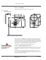
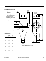
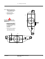
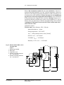
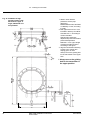
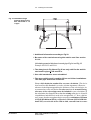
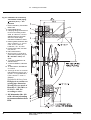
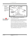
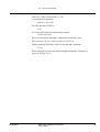
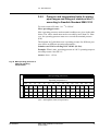
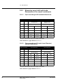
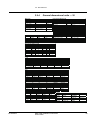
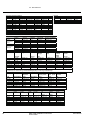
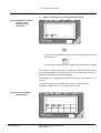
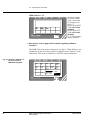
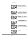
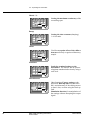
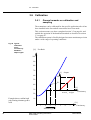
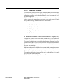
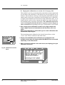
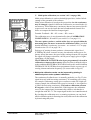
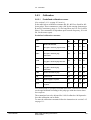
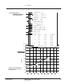
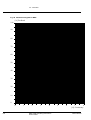
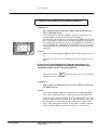
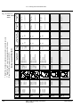
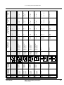
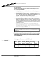
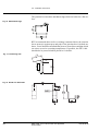
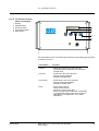
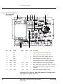
Fig 82 Fuses and test points
6
(TP) on the main
circuit board
4
1
Pos
TP
Label
8
7
9
3
2
Min.
5
Max
Unit
Comment
1
FS1
2
A
Fuse for AC power supply: 250V, 2AT
2
FS2
2
A
Fuse for AC power supply: 250V, 2AT
3
FS3
2
A
Fuse for 24 V DC power supply: 250V, 2AT
4
FS4
2
A
Fuse for DC/DC converters: 250V, 2AT
5
TPØ
GND
Ground reference for all voltages (test points)
6
TP1
+24V
23.5
24.5
V
Output voltage from 24 V DC power supply
7
TP2
+12V
11.5
12.5
V
SPC-1000 supply voltage from DC/DC converter
8
TP3
+5V
4.95
5.05
V
Regulated system supply voltage from DC/DC
converter
9
TP5
1.23V
1.20
1.25
V
Reference voltage for HART modem
Measure all TP’s between TPØ (GND) and the TP at hand using a
high impedance digital voltmeter
184
MEK-2300: JCT-1100 Junction box appendix
© BTG 2004
AX218.56/3e