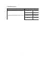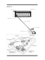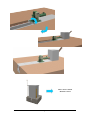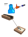
1
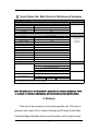
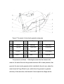
Micro Hydraulic Generator
Single Nozzle Turgo Turbine
ME1201
User Manual
Ver
1.1
1
Bringing you a prosperous future with
clean, reliable, and renewable energy.
Catalog
Ⅰ IMPORTANT SAFETY INSTRUCTIONS ………………………….……….…03
Ⅱ Main Technical Performance Parameters……………………….………… 04
Ⅲ Summary ……………………………………………………………….….…....05
1. Key Technical Data……………………………………………………….………07
2. Station Site and Installation……………………………………………….…..…07
3. Operation
………………………………………………………….……..11
4. Maintenance……………………………………………………………..….….…12
5. Service
……………………………………………………….………..….…12
6. Routine Fault Treatment………………………………………….………….…13
7. Quick-wear parts…………………………………………………….………..…13
Appendix Ⅰ……………………………………………………………………….…14
Appendix Ⅱ…………………………………………………………………….……15
Appendix Ⅲ……………………………………………………………………….…16
Appendix Ⅳ……………………………………………………………………….…17
2
Ⅰ IMPORTANT SAFETY INSTRUCTIONS
This manual contains important instructions that
shall
be
followed
during
installation
and
maintenance of the ME1201.
To reduce the risk of electrical shock, and to
ensure the safe installation and operation of the
ME1201 , the following safety symbols are used to
indicate dangerous conditions and important safety
instructions.
WARNING:
This indicates a fact or feature that is very important for
the safety of the user and / or which can cause serious
hardware damage if not applied appropriately.
Use extreme caution when performing this task.
NOTE:
This indicates a feature that is important either for optimal
and efficient use or optimal system operation.
3
Ⅱ Turgo Turbine Unit Main Technical Performance Parameters
Main Specifications
Turbine
Remarks
Type
Rated Head
Rated Flow
Power
Efficiency
ME1201
12-14m
3-5 l/s
0.3 KW
60%
Turgo Turbine
Generator
Remarks
Type
Rated Power
Rated Voltage
Rated Current
SF-0.3-4/430
0.3KW
120V
2.5A
FQCY
Rated Rotational
Phase
60Hz
1800r/min
1
P.F.
Altitude
Insulation Grade
1.0
≤3000m
B/B
Ingress Portection
IP44
Ambient Temperature
-25℃~+50℃
Relative Humidity
≤90%
Conforms to the
IEC international
electrician
committee
standard
Control Panel
Remarks
Safety Protection
Short Circuit Protection
Islanding Protection
Over Load Protection
Grounding Fault Protection
Fiberboard
17 x 14 x 16 Inches
Packing Material
Packing Size
Packing Weight
Net
Gross
kg
Lb
36
Note: This product or the technical parameters presented may be revised to improve
the technical performance in the future.
Note: The modification of the product's appearance or technical parameters, which
is a result of technical improvements, may be provided in your specific model.
Ⅲ Summary
Thank you for the purchase of a micro hydro generator unit. This series of
generator units consist of the XJ series of turbines and SF series of Rare Earth
Permanent Magnet Brushless Synchronous Generators, with 20 types of single
4
and three phases generators available whose power output is from 200W to
100KW. The user can chose the specific model for the amount of Head and water
Flow on their site.
This series of units is provided with a system to automatically control the
voltage and frequency. The user can turn on or off their electric appliances (TV
sets, recorders, etc) at will on condition that the amount of energy does not
exceed the nominal power output. The user will feel that this power source is just
as convenient as the electrical network.
Before you use the generator units, please make sure that you read this
instruction manual carefully. We recommend that you choose the installation
position of the unit, ditch construction, the inlet conduit installation, the electrical
wire span, and the adjustment of generator unit by consulting a professional.
After the generator unit is installed an operational, we recommend that you perform
maintenance according to the instruction manual and take proper safety electrical precautions.
1) Micro Hydro Station General Description
The typical micro hydro generator station is as follows (figure 1), which
consists of earthwork (inlet conduit construction, unit room and drain etc), the
micro hydro generator, electrical wires, and the users wires.
5
Figure1: The project of micro hydro generator using pipe
1
Penstock
6
Inlet Pipe
-
User
h
Water head
-
Penstock fall
-
Flood altitude
H
Reach fall
11
2
Reservoir
7
Discharge
3
Trash rack
8
Power house
h1
4
Fore bay
9
Electric pole
h2
5
Brook
-
Wire
10
The process is as follows:Collecting the water from the stream in the
reservoir, the water flows into the pipe and runs down hill to create pressure, then
goes into the micro hydro generator which is installed in the unit room, where the
water forces the Turgo Wheel to spin, which drives the generator to generate
electricity. At the same time, the Automatic Control adjusts the voltage and the
6
frequency to meet the requirements for power supply stability so the user can use
the power transmitted in the wires.
2) This kind of Micro-Hydro Generator is consists of an inclined impulse turbine
and a set of direct connected AC single-phase / three-phase generator
(depending on your specific model purchased). The product was designed to be
small, lightweight, with a simple structure, for reliable operation and convenient
assembly. It is intended as a power source of lighting, TVs and recorders, and it
is suitable for households in mountain areas where utility power is unavailable.
The owner can easily install and operate the system themselves, but consult your
local Building Codes, and hire a Contractor if necessary. It is not intended to be
connected to the Utility Power Grid.
7
1. Key Technical Data:
Water Head : 12-14m (39-45 Ft)
Flow (m3/s):0.003-0.005 (47-79 g/m)
Output Voltage (v): 120V (AC) 60HZ
Output Power (kw): 0.3
2. Station Site and Installation:
(1) Power site selection
When choosing a site for the Power Station, remember the following four aspects:
1.1 The Selected power station site should not have a Head lower than 14 meters
head is not lower than 14 meters (45 feet).
1.2 In selecting a power station site, the topography, geological, and hydrological
conditions should be superior, but also the design and construction should be
feasible. During the construction of the micro-hydro power station, remember to
obtain the building materials (such as gravel, etc.) locally as much as possible.
1.3 The selected power station site should be located as close as possible to the
place of use, in order to reduce the electric transmission equipment investment
(copper wire) and the electric power losses, plus for the ease of maintenance and
management. The suitable choice is to install the turbine in the place where there
is drainage, and it would not to be destroyed or submersed by mountain torrents
or flash floods. If the hydroelectric power station site is selected on the hillside,
then you should protect the facility from mountain torrents and the rolling stones.
8
1.4 The selected power station site should make full use of existing hydraulic
structures. For example, use a natural irrigation canal, falling water, or the natural
flow from a reservoir.
(2) Construction of the pressure forebay
The pressure forebay, " forebay" for short., is a pool which is connected between
the irrigation conduit and a pressure pipe. The forebay is composed of the
reservoir, the trash rack, the gate, the overflow, and so on.
2.1 In micro-hydro power stations, the forebay has the following functions:
2.1.1 The forebay can lead the water from the water diversion canal inflow to the
pressure piping. If there are several turbine units, and you need to supply water
to these various pressure piping systems separately, then it will be allocate
enough water to each system equally.
2.1.2 Using a trash rack to prevent tree roots, weeds, and silt in the irrigation
conduit to enter the pressure piping and hydraulic turbine is recommended. In the
winter, it can help to prevent pressure pipe freezing.
2.1.3 The forebay can be used to prevent the current of water from entering the
pressure piping, when the pressure piping or the hydraulic turbine are shutdown
for maintenance.
2.1.4 The forebay can adjust the water volume quickly when the unit is started or
the load is changed, or when the upstream water level changes and becomes to
small. If the available water current capacity is insufficient, you can use the
forebay to store water in the daytime and generate electricity at night.
9
2.1.5 The forebay can discharge the unnecessary water through the overflow
gate to maintain the normal water levels and keep the pressure constant for the
hydroelectric power station.
2.1.6 The forebay can deposit the silt in the canal to reduce wear and tear of
turbine.
2.2 Items for consideration before forebay construction:
2.2.1 The forebay's position should be based on the position of pressure piping
and the Power House position. Choose a stable and solid foundation, small
water-permeable place which is close to Power House.
2.2.2 The forebay should have a certain large volume and water depth. When the
load of the power plant changes, the forebay’s water level may fluctuate but still
provide enough power to the plant
2.2.3 The drainage ability of the forebay's overflow gate ought to meet
requirements when the Power House is at maximum current capacity and the
turbines rejected all load.
2.2.4 When you install the unit, you must certain set up a trash rack in the water
inlet. The trash rack’s hole size is generally 1/3 of the hydraulic turbine nozzle
diameter to guarantee that sundries into the hydraulic turbine will not clog
(restrict) the nozzle.
2.2.5 The size of trash rack should be three times than pressure pipe’s mouth
size. Its function is to guarantee there is enough water to make the turbine work
normally, but also to reduce the frequency of cleaning and maintenance when the
1
0
trash rack in the pressure pipe mouth is partly blocked by debris
2.2.6 You should install the second trash rack at the entrance of forebay if there is
a lot of debris in the canal. You must clean up the debris on the trash rack
frequently when the unit is running.
2.2.7 When you install the trash rack in the forebay, it’s inclination should be 30 °
~ 60 °. If you arrange it 90 °, it will be easily blocked by debris
4) The base structure may be built from local materials. You can make a round
hole which has the same diameter as the lower inner circle of the turbine frame
by using cement, wood, sheet metal, etc, and fasten it with screws or round nails.
It should be positioned horizontally. The surface for drainage must be away from
the bottom of base for 20-30cm (8-11 inches). It must be covered with a proper
shelter to protect from rain and sunlight when the unit is installed outdoors.
3. Generator Operation Method:
1) First, check whether all components are connected and the intake of the
penstock is clear of debris
2) Second, check whether the runner in the turbine can be easily rotated, and
rotate in by hand to ensure the voltage meter has readings (put the output switch
in On position, but disconnect the output from your loads).
3) Third, the first time you start the Generator, the output switch should be put in
the voltage-stabilized control position (On) with no load connected. Rotate the
Nozzle Handle and gradually increase the amount of water, observing the meter
11
readings until you see120v, and the voltage is constant (meter does not fluctuate).
At this time the load can be connected, and you can again adjust the water
volume to hold the output of 120v.
4) During the operation, the load should be kept as stable as possible. Don't shut
off a load suddenly, or else the high voltage spike can be generated and damage
sensitive electronic equipment.
5) To turn off the power, you should turn off the water valve (rotate the handle)
first. This should be done when the power is not required to save your Bearing
life, and reduce the wear on the mechanical components.
4. Maintenance:
1) To check and clean any mud and foreign material blocking in the intake house
and trash rack.
2) The bearing in the generator should be injected with water-proof grease by
using the grease cup knob every three months, by rotating the grease cup knob
three times. The upper bearing also needs maintenance and waterproof grease
should be added every six months.
3)
If the generator becomes wet for any reason, it should be allowed to dry
before it's next use or operation.
1
2
5. Service Rules:
1) If the unit stops operation, please handle it according to the Routine Faults
Treatment List. Please send it to professional or the Distributor if it must be
dismantled.
2) The unit has a 1 year manufacturers warranty for parts due to manufacturing
defects. We do not cover labor, return shipping, or damaged caused by improper
installation or maintenance.
3) For questions or Service, please contact Motenergy, Inc, Slinger, Wisconsin,
United States of America. Phone 262-644-7525. Website: www.Motenergy.com
6. Routine Faults:
Faults
Cause and treatment
Low water volume when the unit is switched on. 1. There is foreign material blocking the
nozzle. Clear it.
The generator cannot be started.
2. Open the valve to reject air.
The voltage meter displays a reading, but the The fuse has been burned out, replace it
indicator and load lamp does not light.
Voltage does not increase to 120 VAC
1.The water volume is too low, increase it
2.Reduce the heavy load
The fuse is burned out
Short-circuit. Check and repair it.
The load cannot be entirely carried.
The drop is too low. Replace the nozzle by a
larger one if water volume is proper.
1
3
7. Quick-Wearing parts:
Item
Specification
1.Single-row radial ball bearing in lower end cover
2. Single-row radial ball bearing in upper end cover.
1
4
200W300W---6203
750W---6204
500W---6204
1100W---6205
200W300W---6202
750W---6204
500W---6204
1100W---6205
Appendix Ⅰ
Overflow
Pool
Transhrack Fence
Water Pipe
Control Box
Electrical Valve
Appendix Ⅱ
1
5
Micro Power Station
Reference Look
1
6
Appendix
Ⅲ
1
7
Appendix Ⅳ
Add lubricant
1
8