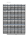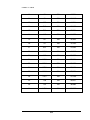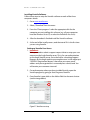
1
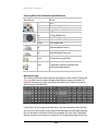
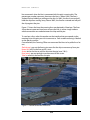
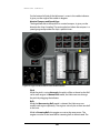
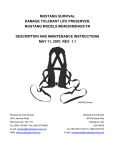
Version 2.8 Interactive Bridge Training Simulation & Environment Suite User Manual ANGLE VISION UNLIMITED WAVELORE ANGLE Vision Unlimited 7406 Alban Station Court Suite A112 Springfield, VA 22150 Toll-free 1.800.866.6402 Phone 703.866.0060 • Fax 703.866.0063 Table of Contents Overview ................................................................................... 1 Software Features ............................................................................. 1 Hardware Features ............................................................................ 2 Look and Feel ................................................................................... 3 Installing Updates ...................................................................... 4 Display Settings ......................................................................... 5 Ogre Display Settings ........................................................................ 5 WaveLore Display Settings ................................................................ 7 Quick Reference Display Settings ....................................................... 8 Starting WaveLore...................................................................... 9 Finding Your IP Address .................................................................. 10 Finding Your Port Number ............................................................... 10 Computer Start Sequence................................................................ 10 Screen Saver, Sleep Mode and Time outs .......................................... 11 Turning Off Screen Savers and Sleep Mode ....................................... 11 Roles in WaveLore .................................................................... 12 Role Selection ................................................................................. 13 WaveLore Controls ................................................................... 14 Server Controls ............................................................................... 14 Instructor Controls .......................................................................... 14 Conning Officer Controls ................................................................. 20 Helmsman Controls ........................................................................ 25 Bearing Taker/Lookout Controls....................................................... 27 Navigator Controls .......................................................................... 27 Scenarios ................................................................................. 28 Current Editor .......................................................................... 29 Networking ............................................................................. 31 Record and Playback ................................................................ 32 The Recorder Role ........................................................................... 32 Controls ......................................................................................... 32 Recording....................................................................................... 36 Playback ......................................................................................... 36 Advance and Transfer ............................................................... 37 Speed Table............................................................................. 40 Radio Communications ............................................................ 42 Index....................................................................................... 46 O V E R V I E W Chapter 1 Overview W aveLore is a multi-user interactive bridge team training simulation and environment suite developed by ANGLE Incorporated. WaveLore combines a stunning visual presentation with high-resolution content, a physics-based dynamic ocean, and enveloping acoustics. WaveLore creates an exceptional virtual training environment for Sea Warrior education, experimentation, and qualification. WaveLore uses either local area or wide area networking and is designed to accommodate multi-team network setups. The WaveLore Suite consists of six computers each with the ability to play one of six first-person interactive roles—Instructor, Radar Operator, Helmsman, Bearing Taker/Lookout, Navigator, or Conning Officer—and participate cooperatively in the operation of an Arleigh Burke class destroyer. Software Features WaveLore is a Windows OS-based training simulation. Each asset in the WaveLore Bridge Team Trainer is created from multiple sources in order to provide the user with a visually stunning environment customized specifically to their training needs. Included features are: • • • Accessible for a Team of Users The WaveLore Suite has 6 possible roles including an Instructor, Conning Officer, Helmsman, Navigator, Radar Operator, and Bearing Taker/Lookout. Flexible Control of Ships The course and speed of all vessels can be controlled by the Instructor. However, when the Helmsman is connected to the Server the Instructor is unable to adjust the course and speed of the DDG. Multiple Custom Ship Models All ship models are created from a variety of sources including analysis models, drawings, and photo reference to create detailed and accurate models. For more information on purchasing additional customized ship models please contact us at 1-800-866-6402 or email us at [email protected] 1 O V E R V I E W • • • • • • Physics-based Ocean Surface and Ship Models In-house developed algorithms replicate the actual physics relationships between the ocean and the DDG. Multiple Sea States/Wind Control As the ocean surface changes due to increased wind, the ships show increased pitch and roll. Navigation The harbor allows users to become familiar with ingress and egress from a commercial harbor, and to develop their piloting skills, along with practicing navigation using GPS, compass, and charts. Custom Harbor Model Special attention is paid to navigation points, channel markers, and docks to ensure the virtual environment closely matches the real world. For more information on purchasing additional specific or customized harbors please contact us at 1-800-866-6402 or email us at [email protected] Day/Night Modes WaveLore has both day and night modes which can make the same scenario a completely new learning experience. With high-quality assets, accurate harbors and navigation, and a visually stunning world, the user is able to gain valuable experience in a safe group training environment. Multi-team Network Setup This version of WaveLore introduces the Multi-suite networking feature. This feature allows one (1) WaveLore Suite to participate in the same network with other WaveLore Suites. Hardware Features WaveLore is built around commercial-off-the-shelf hardware and simulation technology using modular design approaches to provide functional components to match customer requirements. Here are some of the hardware features for a baseline WaveLore Suite: • • • • • • • • • 4 PCs with Intel® Core™ 2 Duo CPU(s), 500 GB HDD, 4 GB RAM, NVIDIA® GeForce 200-series video card or better 2 PCs with Intel Core i7 CPU(s), 500 GB HDD, 4 GB RAM, NVIDIA GeForce 200-series video card or better. 1 PCs with Intel Core i7 CPU(s), 500 GB HDD, 4 GB RAM, NVIDIA GeForce 470 video card or better. 5 keyboards and mice, 3 Xbox® 360 controllers Logitech® G25 Racing Wheel Networking and power supply peripherals 1 touch screen computer monitor with peripherals 4 wide-screen computer monitors¹ 3 wide-screen TV displays with peripherals¹ ² 2 O V E R V I E W ¹These items can be purchased separately. ²Three (3) wide-screen monitors or TV displays must be compatible with Matrox® TripleHead2Go™ graphics expansion module. Look and Feel WaveLore is a fully customized training environment. The pilot house of the Arleigh Burke presented here is an accurate representation of a real DDG. All models have been constructed and textured to a standardized level of detail that balances realism with the processing power of current video card technology. For more information on purchasing custom harbor models or additional ship models please contact us at 1-800-866-6402 or email us at [email protected] 3 I N S T A L L I N G U P D A T E S Chapter 2 Installing Updates W aveLore software requires updates for the latest video card, and hardware drivers, and any new content that is created by Angle Vision Unlimited. Detailed instructions are provided with your update discs to help you quickly and easily update your system. Basic instructions are as follows for any WaveLore updates: Step 1: Install all video card and hardware driver updates. These drivers can be found on the disc labeled “WaveLore Software Drivers”. The following are regularly updated drivers to be installed on all computers: • Microsoft DirectX® • NVIDIA video card drivers • NVIDIA PhysX® The following are regularly updated on specific computers: • Helmsman (where the wheel is attached) – Logitech® wheel driver • Conning Officer – The device that connects the 3 screen displays, Matrox® drivers for the TripleHead2Go™ expansion module Step 2: Install WaveLore updates. These updates can be found on the disc labeled “WaveLore Software Installation”. Step 3: Restart your computers Step 4: Bring all computers online and test connectivity Once the computers have successfully been updated WaveLore is ready for classroom use. 4 D I S P L A Y S E T T I N G S Chapter 3 Display Settings D isplay settings for WaveLore can be configured quickly with two steps. The first step is through the Ogre “ResTool.exe” and the second is in WaveLore’s display settings. Ogre Display Settings The System Administrator or Instructor will need to check the settings for each role every time WaveLore is updated or installed. The display setting list can be scrolled through, and when selected, it provides options to change the settings in the drop down menu at the bottom of the window. See Figure 2, Figure 3, and Figure 4 below for examples of what to change. To change settings in Ogre go through the following steps: 1. Go to where WaveLore is installed on your computer. 2. Navigate to the /WaveLore/bin folder. 3. Double-click “ResTool.exe” and a window for Ogre Display Settings will appear. See Figure 1 below for an example of the Ogre Display Settings window. 4. Select “Full Screen: Yes” for all roles except the Server. Toggle Yes or No by using the drop-down menu at the bottom of the window. 5. Select “VSync: Yes” for all roles. Toggle Yes or No by using the drop-down menu in at the bottom of the window. This maintains visual synching between all the different roles. 6. Set the resolution “Video Mode:” by using the drop-down menu to select the correct resolution of the display you are using. Use the “Quick Reference Display Settings” found in Table 1 to find the settings for each role. 7. Press “Ok” to accept the settings 8. Launch WaveLore.exe 5 D I S P L A Y S E T T I N G S Figure 1: Ogre Display Setting menu launched from the “ResTool.exe” Figure 2: Menu showing the selection for Full Screen Figure 3: Menu showing the selection for synching the views in all the roles 6 D I S P L A Y S E T T I N G S Figure 4: Menu showing the resolution selections possible on a particular computer. WaveLore Display Settings Aspect ratio can be adjusted in WaveLore while at the Initialize Menu. See Figure 5 below, for an example of the menu. To access these settings: 1. Press Alt + O 2. Select the appropriate aspect ratio: a. Default – is the previously selected aspect ratio b. 4:3 – Standard TV/non-widescreen monitor c. 16:9 – Standard Widescreen TV d. 16:10 – Standard Widescreen Computer Monitor 3. 16:9 and 16:10 are for the three-screen setup on the Conning Officer role, and any widescreen monitors. 4. 4:3 is for standard non-wide screen TV/Computer aspect ratio. 5. Continue launching WaveLore Figure 5: WaveLore Display Settings Menu 7 D I S P L A Y S E T T I N G S Quick Reference Display Settings Note that on computers with better quality video cards there will be higher resolution selections. Here are suggested display settings for each role: Table 1: Resolution settings for each role Role Full Screen VSync Server No Yes Instructor Conning Officer Helmsman Radar Operator Bearing Taker/Lookout Yes Yes Yes Yes Yes Yes Yes Yes Resolution 800x600 or 1024x768 1360x768 3840x1024 1024x768 1680x1050 Yes 1680x1050 Navigator Yes n/a n/a 8 The resolution should be set to the suggested resolution required for RayMarine® RayTech Navigation Software S T A R T I N G W A V E L O R E Chapter 4 Starting WaveLore A WaveLore Suite consists of multiple computers networked together with a main server controlling the network traffic and keeping the simulation synched. All WaveLore computers have an initialize menu that consists of two fields: (1) The IP address of your server, and (2) the Port Numbers available on your server. See Figure 6 below for a look at what an Initialize Menu looks like: Figure 6: Screen capture of the Instructor Initialize Menu The Server Initialize Menu (Figure 7, below) is unique in that it allows the server computer to either be a host server, or connect to another server. The connect function is for joining two WaveLore Suites together that are located on different networks. More about this is covered in the Networking Chapter. Figure 7: Screen capture of the Server Initialize Menu 9 S T A R T I N G W A V E L O R E Finding Your IP Address Start up the computer, run WaveLore, select the server in the role menu. Once the server in WaveLore is running it will display the computer’s IP address. Alternatively, IP addresses for any computer can be found with the following steps: Step 1—Go to Start/Programs/Accessories/Command Prompt Step 2—Type in “ipconfig” in the command prompt and press Enter. See Figure 8 below for where to look for your IP address: Figure 8: Command Prompt showing where to find your IP address. IP address is circled in red. Finding Your Port Number The Port Number allows other computers in your WaveLore Suite to send and receive data from the server. The server will have certain ports that you can select from the menu. It is important to note which port number you have selected so that the correct port number is entered or selected on each machine connecting to the server. Computer Start Sequence Here is the sequence for starting up the various computers that are part of your WaveLore Suite. 1. First start the server 2. Then start the Instructor seat 3. Connect the Instructor seat to the server by using the server’s IP address and port number in the initialize menu. 10 S T A R T I N G W A V E L O R E i. **Note: The Instructor or System Administrator will need to ensure that all the computers connecting to the server use the server’s IP address and port number 4. Next, start up the Helmsman seat and connect it to the server 5. Finally, bring the remaining computers up and connect them to the server (Conning Officer, Bearing Taker/Lookout, Radar Operator, and Navigator). Screen Saver, Sleep Mode and Time outs System Administrators and/or Instructors should check all computers that are part of the WaveLore suite to ensure the following: 1. Screen savers are disabled 2. Sleep and hibernation mode are disabled If computers are setup with screen savers, and/or sleep/hibernation mode this can lead to server disconnection or time outs of other roles. Turning Off Screen Savers and Sleep Mode Screen Savers 1. To disable Screen Savers, right click on your desktop and select “Personalize” 2. Select, “Screen Saver” 3. Select (None) from the drop down menu 4. Click “Apply” Sleep Mode 1. To disable Sleep Mode, go to Start Menu/Settings/Control Panel 2. Select, “Power Options” 3. On Windows Vista, in the menu at left, select “Change when the computer sleeps” 4. Use the drop down menu for “Turn off the display” and select “Never” 5. Use the drop down menu for “Put the computer to sleep” and select “Never” 11 R O L E S I N W A V E L O R E Chapter 5 Roles in WaveLore S ix (6) first-person interactive roles are available in WaveLore: Instructor, Radar Operator, Helmsman, Bearing Taker/Lookout, Conning Officer, and Navigator. This chapter highlights what each role can do. Note that some roles have similar capabilities. For example, some of the tools in the Conning Officer role are the same as the Bearing Taker/Lookout role. Server The Server while not technically a role is available as a selection in the role menu, allows the Instructor to connect all the other roles together so that multiple users can cooperatively experience the WaveLore bridge team training simulation. The server also helps the Instructor keep track of what roles and contacts have joined or not joined the simulation. In the multi-team network setup, the server can be a Host Server that the servers of other WaveLore teams can connect to. Instructor The Instructor role is able to control the main DDG’s course and speed, place/remove contacts in the WaveLore environment, control the course and speed of contacts, control wind speed and direction, change to day or night mode, and/or run a man-overboard scenario. Instructors also have the ability to save scenarios and load saved scenarios for other students to work through. Radar Operator The Radar Operator role will be able to track contacts and find bearings of contacts that appear on the radar display. Contacts appear as blips in their relative locations. Helmsman The Helmsman role will use a touch-screen and wheel to control the course and speed of the DDG. Once the Helmsman is in control of the ship, the Instructor will no longer be able to edit the course and speed of the DDG. The Instructor may however drag the DDG around while in the Scene Map View. 12 R O L E S I N W A V E L O R E Bearing Taker/Lookout The Bearing Taker/Lookout’s role can be run on one (1) computer with the ability to toggle from each bridge wing, or two (2) computers allowing for two students to engage as Bearing Taker/Lookouts for each bridge wing. This role is stationed on the bridge wings only and allows users the ability to provide bearings using alidades; and view other ships and landmasses using binoculars. Conning Officer The Conning Officer role will be able to move freely throughout the pilothouse of the DDG and out to either bridge wing. The Conning Officer is responsible for coordinating the crew. He/she has the option of using alidades at port, center, and starboard; as well as the binoculars to observe other ships. The Conning Officer must also deploy a smoke and life ring into the water when a manoverboard event occurs. Navigator The Navigator role does not take place in WaveLore’s simulation software. The WaveLore Server and the computer running the Raymarine RayTech navigation software will be connected allowing the WaveLore server to transmit simulation coordinates into real world coordinates that can be tracked on the Raymarine RayTech GPS navigation software. Recorder Like the server, the recorder is not technically a role but is available as a selection in the role menu. The Recorder allows the Instructor to create a recording of a simulation for later playback and review. The use of the Recorder is covered in more detail in the Record and Playback Chapter. Role Selection Figure 9 shows the Role Selection menu that appears after WaveLore loads. This menu gives you the option of choosing the role of Instructor, Radar Operator, Helmsman, Conning Officer, Bearing Taker/Lookout, Recorder, or Host Server. The Navigator client is restricted to the machine on which the Raymarine RayTech GPS navigation software is installed, so that role does not appear in this menu. The host server machine must be running in order for networking to be enabled. Figure 9: Screen capture of the Role Selection menu. 13 W A V E L O R E C O N T R O L S Chapter 6 WaveLore Controls T his chapter will introduce and explain the controls available for each role. Some roles have limited controls and others have multiple menus to interact with. Server Controls The server has one menu for interaction which gives Instructors the option to run a server or connect to Host Server. The Instructor simply makes a selection of either “Host” or “Connect”. See Figure 10 below for an example of the menu. **Note: On the keyboard the Server can reset the DDG by pressing the T key. Figure 10: Server Initialize menus for starting a host server or connecting to a host server. Instructor Controls The instructor is responsible for setting scenarios in WaveLore. Once the Instructor role has been selected, the Instructor Menu Bar will appear at the top of the screen. The Instructor menu bar consists of seven menus (Figure 11, Figure 12). The menu bar allows the Instructor to add/edit contacts, adjust the sea state using the wind controls, and change from day to night using the time control menu. 14 W A V E L O R E C O N T R O L S Figure 11: Screen capture of the Instructor’s Menu. When clicked, each menu drops down to reveal selections and fields to add variables (Figure 12). Figure 12: Menus in the Instructor’s Menu Bar. DDG Menu The DDG Menu allows the Instructor to change the course of the DDG immediately or over time, and the speed of the DDG immediately or over time. Adjusting the course and speed of the DDG 1. While in the DDG Menu, enter the new course and speed 2. Enter the time, in seconds to reach the specified course and/or speed 3. Click apply Buttons in the DDG Menu Go To — Clicking on this button will lock the Instructor’s view to a camera on the ship’s bridge. Leave — Once “Go To” a ship has been selected; the “Go To” button becomes the “Leave” button. When you click on it, the ship will move on without the Instructor. The Instructor’s view is no longer locked to the DDG’s pilothouse. Apply — This button applies the values entered in the fields. Moving in Standard/Normal View The Instructor can move around the scenario using an Xbox360 Controller or by using a keyboard and mouse. See Figure 13 for a visual detail of the Instructor movement controls on the keyboard/mouse and Xbox controller. Keyboard/Mouse Controls— Change the viewing perspective by holding down the Right-mouse button while using the W, A, S, D keys to respectively move up, left, back, right. 15 W A V E L O R E C O N T R O L S Xbox 360 Controls— Change the viewing perspective using the right joystick while using the left joystick to move up, left, back, right. **Note: When using the Xbox 360 controller, hold the right trigger button then use the left joystick to move forward to boost movement speed. Using the Xbox360 Controller as an Instructor Using the Mouse as an Instructor Hold down and move to let the instructor look around. Hold down trigger to increase speed Used for changing selection of parameters only. Does not effect the camera Move Left, Right, Forward, or Backward Look Around Figure 13: Illustration of the mouse and Xbox 360 controls. Contacts Menu All contacts that are added into a WaveLore scenario appear here in a list. When more than three (3) contacts are added a scrollbar is available to access other contacts. Each contact can have its course changed immediately or over time, and speed changed immediately or over time. Adjusting the course and speed of a contact 1. Select a contact that you wish to adjust the course and speed for 2. Enter the new course and speed 3. Click apply Buttons in the Contacts Menu Go To — Clicking on this button will lock the Instructor’s view to a camera on the ship’s bridge. Leave — Once “Go To” a ship has been selected; the “Go To” button becomes the “Leave” button. When you click on it, the ship will move on without the Instructor. Remove — This button removes the selected contact from the environment. Apply — This button applies the values entered in the fields. 16 W A V E L O R E C O N T R O L S Man Overboard Menu For simulating a man-over-board scenario this menu provides the Instructor with the option of randomly inserting a sailor into ocean on either the port or starboard side of the DDG. The bridge team will have to react accordingly to rescue the sailor. Placing a Man Overboard 1. Use the Man Overboard menu and select either port or starboard side to drop a sailor overboard. 2. Zoom in to where, Oscar, the Man Overboard Avatar is positioned in the sea then click and drag him to reposition. 3. Direct students to react accordingly to rescue Oscar 4. The cancel button will appear which allows the Instructor to end the scenario at any time. **Note: After a smoke and a float have been dropped by the Conning Officer they cannot be dropped again until the Instructor cancels the MOB scenario and places Oscar overboard again. Scenario Control Menu This menu allows the Instructor to save the current settings and attributes of your scenario. The scenario can then be loaded and replayed. This is particularly helpful if an entire class is given the chance to work through the same problem in different groups. Save a Scenario 1. Use the Scenario Control menu and enter a name for the scenario to be saved. 2. Click “Save” Load a Scenario 1. Use the Scenario Control menu and select the name of the scenario to be loaded. 2. Click “Load” **Note: This currently saves all ship orientation, velocity, position, time of day, and wind settings for the DDG and all contacts within the scenario. Add Contacts Menu When this menu is activated, the screen changes to a top down view of the WaveLore environment. The Instructor can then add contacts to a scenario. Adding Contacts to a Scenario 1. Click on the “Add Contact” menu while in Scene Map View. 2. Select a contact to drop into the scene. 17 W A V E L O R E C O N T R O L S 3. Use the small green dot which appears near the beginning of each contact title to drag the cursor/contact to desired location on scene. 4. Click to drop the contact into the scene. Available Types of Vessels The current available contacts include: additional DDGs, a naval supply ship, a civilian tanker, a civilian Freighter, a Chinese Destroyer (051B Destroyer, Shenzhen), and a Tugboat. For more information on purchasing additional custom ship models please contact us at 1-800-866-6402 or email us at [email protected] Turning Scene Map View On/Off 1. Press the Tab key to toggle between the Standard View and Scene Map View. See Figure 14 below for the difference between the two views. Standard View Scene Map View Figure 14: Screen captures of the Standard/Normal View and the Scene Map View in WaveLore Moving in Scene Map View • While in Scene Map View, change the view by holding Ctrl and left clicking on the desired location on the scene map. This will instantly transport the Instructor’s view to the cursor location. • Use the W, A, S, D keys to respectively pan up, left, down, right while in Scene Map View. Zoom In/Out in Scene Map View 1. Right clicking on the ocean scene will allow you to zoom in to a view of 40X40 nautical miles of ocean, centered at the location of the cursor. 2. Right click a second time to zoom in to a view of 4X4 nautical miles. 3. A third right click will give you back the original scene map. The dimensions of the original scene map are 250 X 250 nautical miles. Turning the Grid on in Scene Map View 1. Press the G key 18 W A V E L O R E C O N T R O L S 2. A grid will appear along the edges to indicate the range of the scene map. This grid is intended to simplify the contact insertion process. Wind Control Menu Using this menu you can control wind speed and wind direction. This will affect the ocean surface and in turn the pitch and roll of ships you have placed in your scenario. **Note: The wind direction is a “to” direction not a “from” direction. Harbor Control Menu This menu allows the Instructor to select harbors to train in and to toggle from day to night. Recorder Control Menu This menu allows the Instructor to control the recorder. The use of the Recorder is covered in detail in the Record and Playback Chapter. Screen Capture 1. Press F12 and a screen capture will be saved in jpeg format to the\WaveLore2\WaveLore 2.0\screenshot directory. 2. This will help Instructors save images that highlight teaching points to bring up later for class-wide discussion. Scenario Changes While WaveLore is Running WaveLore has to dedicate some memory to loading the new vessels, or sea state changes. This will cause a small but visible pause during the simulation. WaveLore Memory Management Prior to running a scenario, the Instructor should do the following steps to limit the amount of data that WaveLore has to load: 1. Add all the contacts to be used in the scene 2. Delete all the contacts from the scene that are not immediately needed. a. Now that the contacts have been loaded into memory, any contacts that were previously added can be added during the scenario without causing a long pause. 3. Toggle the day and night mode on and off. Then set the mode that you wish to start with. 4. Run the scenario. Quitting/Exiting WaveLore 1. To exit WaveLore hold down the ALT button on the keyboard and press the F4 key. 2. In order to switch roles within the simulation you must first exit the program then rejoin the server. 19 W A V E L O R E C O N T R O L S Conning Officer Controls The Conning Officer role can be used on either a single screen display or with three-screens. Using a Keyboard and Mouse Here are the different controls possible for the Conning Officer using a keyboard and mouse. Movement 1. Press the W or Up Arrow key to move forward 2. Press the A or Left Arrow key to move left 3. Press the S or Down Arrow key to move backward 4. Press the D or Right Arrow key to move right 5. Change the viewing perspective by holding down the Right-mouse button while using the W, A, S, D keys to respectively move up, left, back, right. Binocular Mode 1. Press the F5 key to toggle on Binocular Mode. 2. While in this mode, the binoculars can be zoomed in and out with + and keys. 3. Turn the binocular mode off to select Alidade Mode Alidade Mode 1. Use the F2, F3, and F4 keys to switch alidade views on the port side, bridge, and starboard side respectively. 2. Press the F1 key to return to normal view. Laser Range Finder 1. Press and hold the Tab key to activate the laser range finder. 2. Use the mouse to aim at other vessels. 3. Press the Q key to toggle between the port and starboard side laser range finder. Man Overboard 1. Press the Insert key to drop a smoke and float over the port side. 2. Press the Page Up key to drop a smoke and float over the stbd side. Using an Xbox Controller Here are the different controls possible and what they do using an Xbox controller. 20 W A V E L O R E C O N T R O L S Binocular Zoom Out Binocular Zoom In Y: Toggle Binoculars Move Left, Right, Forward, or Backward Look Around Alidade Figure 15: Controls on the Xbox controller Movement 1. Use the left and right joysticks as in Figure 15 2. The left joystick is for moving around in space 3. The right joystick controls where the current view Binocular Mode 1. Use the Y button to toggle on Binocular Mode. 2. Zoom with Left (LB) and Right (RB) shoulder buttons. Alidade Mode 1. Use the D-pad Up Arrow for the Central alidade view 2. Use the D-pad Left Arrow for the Port alidade view 3. Use the D-pad Right Arrow for the Starboard alidade view 4. Use the D-pad Down Arrow to exit alidade view Laser Range Finder 1. Use the Back button to activate the laser range finder 2. Use the right joystick to aim at other vessels 3. Press the Start button to toggle between the port and starboard side laser range finder Man Overboard 1. Press the B button to drop a smoke on the starboard side 2. Press the X button to drop a smoke on the port side 21 W A V E L O R E C O N T R O L S Conning Officer Xbox Controller Quick Reference Xbox Button A B X Y Action -n/a Drop Smoke Starboard Drop Smoke Port Toggle Binocular Mode Up Left Right Down Center Alidade view Port Alidade View Starboard Alidade View Exit Alidade View LB Binocular Mode Zoom In RB Binocular Mode Zoom out Back Activate laser range finder Start Toggle port side and starboard side laser range finder display Mooring the ship The Conning Officer can command the mooring lines while at dock. Clicking the Mooring button on the screen will open the interface to give commands. (In order for the mooring system to function, the Helmsman’s station must be up and running on the network). Figure 16 : Mooring GUI. Left: Lines all in. Right: Lines all out. In the Figure 16, the image on the left shows the line commands when the lines are not in use. The buttons to the right of each line represent the eight mooring bitts on the dock to which the line can be attached. Once the ship is alongside the pier, the lines can be thrown to each bitt. The image on the right shows the 22 W A V E L O R E C O N T R O L S line commands when the line is connected with the pier’s mooring bits. The percentage number represents how tense the line is. Below 100%, the line is slacked and not holding or pulling on the ship. At 100%, the line is taut and will hold the ship from moving away. Above 100%, the line has strained and will pull the ship against the pier. Figure 17 shows the how the mooring lines are depicted in WaveLore. The lines shown do not represent how loose or tense the line is, rather simply indicate which connections are made between the ship and the pier. To send out a line, select the number on the interface that corresponds to the mooring bit on the pier you wish to connect to. Each useable mooring is labeled on the pier by number. Once attached, the Conning Officer can command the lines to be pulled in or let out. Slack (away): pay out the line to give room for the ship to move away from pier. Heave (in): pulls in the line until it is taut. Strain: tenses the line to pull the ship into the pier (max 120%). Ease (away): pay out enough to remove most of the strain. Take In: removes the line from the pier. Figure 17 : Positions of the lines on the DDG 23 W A V E L O R E C O N T R O L S Radar Operator Controls The Radar Operator role allows the bridge team to track contacts and monitor position from land. Any contacts within the maximum range of the radar display will be shown on the radar as blips in their relative locations. See Figure 16 below for an example of the Radar Operator display. Figure 18: Radar Operator view Changing the Range of View 1. Press the Up and Down Arrow Keys on the keyboard to change the maximum range of the radar display between 1, 2, 5, 10, 20, and 40 Nautical Miles. 2. The user can also use the mouse and left click the zoom level display (upper left corner) with the mouse to change the range. 3. The current range of view can be seen in the upper left corner. Toggling between Ships Head Up and True North Modes Two different radar modes can be toggled by pressing the Spacebar or by clicking the mode display: Ships Head Up Mode – 000 at the top of the radar indicates the direction the ship is moving. True North Mode – 000 indicates North. 24 W A V E L O R E C O N T R O L S 1. The red marker on the degree scale indicates the heading of the student’s ship. 2. The radar mode selected can be seen in the upper left corner. Finding Contact Bearings 1. Left click the radar display to create a temporary marker of a contact. 2. View the contact’s bearing and distance from the ship in the upper right corner of the screen. Helmsman Controls Helmsman controls consist of the touch screen and wheel. The touch screen displays the throttle controls for the DDG which consist of a rudder indicator, a compass, speed gauge, and pitch and bells. The wheel features a button for the DDG’s horn. Setting up the Touch Screen When the touch screen is first connected it must be configured to operate accurately. Here are the steps for setting up the touch screen: 1. Run the Touch Configuration Application from the software that came with the monitor. 2. Navigate to the calibration menu and calibrate the screen for 25 points. 3. Push on the center of each circle for a couple of seconds and then release. 4. Once it is recognized it will display the next circle to touch until all 25 points have been recorded. **Note: The touch screen display must be set to 1024x768 using the Configuration. This is to ensure that the controls display properly and do not appear cut-off. Wheel and Touch Screen Throttle The wheel and throttle controls on displayed on the touch screen (Figure 17) are the Helmsman controls for the DDG. Figure 19: Helmsman's wheel and touch screen display Rudder Indicator 25 W A V E L O R E C O N T R O L S On the bottom left side of the Helmsman’s screen is the rudder indicator. It gives you the angle of the rudder in degrees. Nautical Compass and Speed Gage The large black dial at the top left is a nautical compass; it gives you the direction the ship is heading. The rectangular box below the compass is a speed gauge and provides the ship’s speed in knots. Figure 20: Large view of the touch screen throttle controls Pitch While the pitch is set to Automatic, the pitch will be set based on the Bell set for each engine. In Manual Pitch mode, the Helmsman can change the pitch by dragging the indicator. Bells While the Maneuvering Bells mode is selected, the Helmsman can modify each engine separately. The engines can only be set from one bell to the next. While in Steaming Bells, the engines are set to the same power. The engines must be at the same Bell for steaming bells to be activated. The 26 W A V E L O R E C O N T R O L S Helmsman can drag the throttles to the desired power or use the + and – icons to increase the engines by a single mark. Ship Horn Using the small red button on the left side of the steering wheel the Helmsman can activate the DDG’s horn. Bearing Taker/Lookout Controls View Movement 1. Change the viewing perspective by holding down the Right-mouse button to move left and right. Binocular Mode 1. Press the F3 or Right Arrow key to toggle on Binocular Mode. 2. While in this mode, the binoculars can be zoomed in and out with + and keys. 3. Press the Left Arrow key to switch to normal view. Alidade Mode 1. Use the F2 or Up Arrow key to switch to alidade view. 2. Press the Spacebar key to return to toggle port and stbd alidades. 3. Press the F1 key to switch to normal view. Navigator Controls The Navigator role must be on a computer connected to the server station via a null modem cable. 1. Start the server and select a com port 2. Launch the Raymarine RayTech software 3. Make sure the appropriate charts are loaded. Check the Navionics CF card and ensure it is the Navionics XL9 - Mid America and Caribbean - CF Card Unit. 4. The Raymarine RayTech software will auto-detect a signal coming from the server computer. 5. The server will transmit the ship position from the simulation into real world coordinates reflected on the Raymarine RayTech software. 6. The student in the Navigator role will then be able to track the ship in space and work with the maneuvering board team to determine course corrections/changes for the DDG. 27 S C E N A R I O S Chapter 7 Scenarios T his chapter will provide a quick reference for the steps Instructors should go through when setting up a scenario. 1. Start the Server and identify the Server IP address and port number. 2. Start the Instructor and connect to the Server using the Server’s IP address and port number. Check the Server to see that the Instructor has connected. 3. Use the Server IP address and port number when starting up and connect the remaining roles to the server except the Helmsman. Monitor the Server to see that each role has joined. a. Note: If the Helmsman is connected to the server before the Instructor has finished setting up the scenario he/she will be unable to change the settings of the DDG. 4. At the Instructor’s seat a. Use the DDG menu to setup the course and speed of the DDG. b. Use the “Add Contacts” menu to add contacts to the scenario. c. Use the “Contacts” menu to adjust the course and speed of the contacts in the list above. d. Use the “Wind Controls” menu to adjust the sea state. e. User the “Time Controls” to change to day or night. f. Save the scenario if desired. 5. Allow Helmsman to join the server to take control of the DDG and proceed through scenario. 28 C U R R E N T E D I T O R Chapter 8 Current Editor T he ocean current editor allows the user to modify currents that affect the DDG in WaveLore. The editor can be opened by starting Ocean Current Editor application in the WaveLore folder. Figure 21: Current Editor The arrows represent the direction of ocean currents at that spot. The red dots represent a current node, central point of influence on the current directions around it. By placing nodes into the scene and setting their values, you will influence the direction of the currents. The arrows in the current editor represent the direction of ocean currents at that spot. The red dots represent a current node, central point of influence on the current directions around it. By placing nodes into the scene and setting their values, you will influence the direction of the currents. The user will set the properties of each current node using the editor menu in the upper left corner of the Current Editor. The fields of the editor menu are: Direction Direction is the direction this node will influence the currents to travel in. specified in degrees from North in the first field of the editor menu. 29 C U R R E N T E D I T O R Strength Strength is a modifier to create a greater effect on currents than other surrounding nodes. The strength is specified relatively, the default value is zero and there is no maximum strength value, the bigger the number the more influence the node will have. Range Range is the radius around the node that it will have an effect. The further a point on the grid is away a node, the less influence it will have, up to its range. Figure 22. Current Editor menu Click “Add” to enable dropping a new node into the scene. Once in the scene, a node can be moved by clicking and dragging it to a new location. Click “Apply” to set those values into the node. Click “Remove” while a node is selected to remove it. Click “Save” to save the current settings of the scene. This will generate a file with the settings and can be located in the WaveloreCurrentEditor\configs\release folder. This file must be copied & pasted into WaveLore’s configs\release folder for all WaveLore computers. The - and + keys will allow the user to zoom in and out of the scene. Zoom in closer to get a more precise look at how the currents are flowing. Select different harbors to edit in the harbor list. 30 N E T W O R K I N G Chapter 9 Networking T his version of WaveLore introduces the multi-suite networking feature. This feature allows one (1) WaveLore Suite to participate in the same network with other WaveLore Suites. For ease of understanding, WaveLore suites will be referred to as teams. **Important note: When connecting a multi-suite network setup, the team B Instructor role cannot change simulation settings. It can only observe. Setting up the Host Server Here are the steps to setup a host server for multi-suite networking: 1. Start team A’s WaveLore server normally. Team A’s server will be the Host Server. 2. Be sure team A’s server is connected to the internet and that the router is forwarding the port number to the Host Server. 3. Provide team A’s Host Server IP address and port number to any teams wishing to connect. 4. Have all team A’s other roles connect to the team A Host Server. Connecting Other Servers to the Host Server Here are the steps to connect multiple WaveLore teams together: 1. Connect team B’s server to another network by clicking “Connect” on the host server startup menu. 2. Enter the IP address and port number for team A’s Host Server into the new fields. 3. Now team B’s server is running and connected to team A’s Host Server. 4. Have all team B’s remaining roles connect to the team B server. 31 R E C O R D A N D P L A Y B A C K Chapter 10 Record and Playback V ersion 2.8.0 of WaveLore introduces the Record and Playback feature. This feature allows a recording to be made of all environmental conditions, contacts and crew actions during a simulation for playback and review at a later time. **Note: Record and Playback for multi-suite networking is not supported as of version 2.8.0. **Note: The desired harbor should be selected before beginning a recording and should not be changed during a recording. The Recorder Role The recorder role, unlike other roles, can be used while minimized. Therefore, it can run on the same computer as another role or the Raymarine RayTech navigation software. The Radar Operator station is the recommended location to run the recorder role. Launch Wavelore and select Recorder from the Role Selection menu. Once it has started, minimize Wavelore and launch another instance from the Start menu or desktop icon and proceed as normal. Controls The Record and Playback functions are controlled from the Instructor Station. The button for Recorder Control will be disabled ( grayed out ) if the Recorder Role is not connected. Figure 23. The instructor's menubar showing the Recorder Control option disabled (top) and enabled (bottom). The Recorder Control menu can be displayed in a compact or expanded state. The compact state appears by default. The expanded state can be seen by pressing the 32 N E T W O R K I N G More button. The More button then becomes a Less button that can be used to return to the compact state. Figure 24. The Recorder Control Menu in the Compact state. Figure 25. The Recorder Control Menu in the Expanded state. The controls and fields on the Recorder Control Menu are described in detail in the Figure and list on the next page. 33 N E T W O R K I N G 5 1 3 2 6 7 8 9 10 11 12 14 13 4 15 16 17 18 19 20 Figure 26. Large view of the Recorder Control Menu with the controls numbered according to the descriptions below. 1. Bookmark – click to add a bookmark at the current position on the progress bar. 2. Elapsed Time – the time that has passed in the current recording or playback. 3. Progress Bar – graphical representation of the time elapsed and remaining in the current recording session or playback. 34 N E T W O R K I N G 4. Remaining Time – The time remaining in the current playback, or time left until recording will stop. 5. Bookmark ticks – indicated location of bookmarks in the current recording. Clicking on a bookmark tick will remove that bookmark. 6. Record – begin recording the simulation. 7. Previous – jump to the last bookmarked time before the current elapsed time in the recording, only available during playback. 8. Rewind – move quickly backwards through the recording, only available during playback. 9. Stop – stop recording or playback. 10. Play – begin playback of the recording indicated in the current file field. 11. Pause – pause the playback, the instructor can still move his camera, the Conning Officer can move around the bridge and use the binoculars, alidades and laser range finder. 12. Fast Forward – move quickly forward through the recording, only available during playback. 13. Next – jump to the first bookmarked time after the current elapsed time in the recording, only available during playback. 14. Max. Record Time – select the maximum record time for recording. Recording can be ended earlier with the Stop button. 15. +30 – add thirty minutes to the maximum record time. 16. List of Recordings – list of recordings currently available for playback. 17. Current File – displays the name of the current recording file. 18. Create – create a recording file with the name entered in the Current File field. If no name has been entered, a default name will be used. 19. Load – load the file selected in list of recordings 20. Notes – up to 10,000 characters can be entered to describe the recorded simulation. 35 N E T W O R K I N G Recording Before beginning a recording, the instructor has the option to create a name for the recording by typing it into the Current File box then pressing the Create button. If the Create button or record button is pressed without a name in the Current File box, a default name will be assigned. The default name consists of the name of the harbor, the current date, and the current time. If a recording with the selected name already exists, a “-1” will be appended to the end of the name. The instructor also has the option of selecting a maximum record time from a list. The default value is 60 minutes. The recording will stop when this time has elapsed but the simulation will continue unaffected. If more record time is desired, the +30 button can be pressed to add an additional 30 minutes. This can be done before or during the recording. Press the red Record button to begin the recording. The recording can be stopped at anytime with the Stop button. Bookmarks and Notes can be added during the recording. Playback Select the name of a recording from the Recordings list and press the Load button. Press the Play button to begin the playback. If the wrong harbor is current loaded, the correct one will be loaded automatically before the playback begins. The playback can be paused at anytime using the Pause button. The DDG, ocean and contacts will freeze. However, the instructor’s camera can still be moved around, the conning officer can still move around the bridge and use the binoculars, alidades, and laser range finder. The instructor can use the FastForward and Rewind buttons to move quickly through the playback or the Next and Previous buttons to jump to the next/previous bookmark. 36 N E T W O R K I N G Chapter 11 Advance and Transfer B elow is a table for the advance and transfer of the DDG in WaveLore. The table includes information on the approach speed, rudder angle, how far the DDG advances and transfers in water, and the final speed and turn angle of the DDG. Table 2: Advance and Transfer table Approach Speed 10.1331729 10.1331729 10.1331729 10.1331729 Rudder Angle 10 10 10 10.25 Advance 555.3404273 724.607792 454.3624018 -89.81227269 Transfer 271.7433873 829.5950452 1334.445892 1498.923897 Final Speed 9.591325781 9.588254504 9.583725342 9.580673504 Turn Angle 45 90 135 180 Approach Speed 10.13284245 10.13284245 10.13284245 10.13284245 Rudder Angle 15 15 15 15 Advance 430.447094 549.3954562 330.1424426 -92.25339924 Transfer 217.017205 651.3112279 1035.830605 1151.215135 Final Speed 9.236593293 9.219992847 9.213850293 9.207027393 Turn Angle 45 90 135 180 Approach Speed 10.13218154 10.13218154 10.13218154 10.13218154 Rudder Angle 20 20 20 20 Advance 374.8938319 489.3882507 320.9620141 -29.99627352 Transfer 162.9430615 540.76883 854.9252368 967.4473765 Final Speed 8.893776582 8.854083243 8.843139389 8.836277612 Turn Angle 45 90 135 180 Approach Speed 19.95202588 19.95202588 Rudder Angle 10 10 Advance 581.4137223 778.2351386 Transfer 236.7134269 772.6928887 Final Speed 18.90281547 18.88456275 Turn Angle 45 90 37 S P E E D T A B L E 19.95202588 19.95202588 10 10 544.2549309 36.06284615 1276.33835 1462.234124 18.8634137 18.83604435 135 180 Approach Speed 10.12994612 10.12994612 10.12994612 10.12994612 Rudder Angle 25 25 25 25 Advance 322.3145237 396.0997667 222.1650388 -92.6668136 Transfer 168.8229342 493.774911 769.9224329 841.3008408 Final Speed 8.55931841 8.492916625 8.473944686 8.464886363 Turn Angle 45 90 135 180 Approach Speed 19.94872134 19.94872134 19.94872134 19.94872134 Rudder Angle 15 15 15 15 Advance 433.7917339 548.9388569 333.7763357 -75.35469869 Transfer 215.821969 642.8781999 1016.819468 1126.909782 Final Speed 18.21780408 18.18184292 18.15707832 18.1394282 Turn Angle 45 90 135 180 Approach Speed 19.95513603 19.95513603 19.95513603 19.95513603 Rudder Angle 20 20 20 20 Advance 369.6795834 454.3492083 276.9891085 -57.14659865 Transfer 184.3439964 521.7514775 815.9757556 898.5398646 Final Speed 17.54095684 17.36877094 17.35817698 17.35825474 Turn Angle 45 90 135 180 Approach Speed 19.96427211 19.96427211 19.96427211 19.96427211 Rudder Angle 25 25 25 25 Advance 331.4365146 399.8407336 255.2533013 6.180635631 Transfer 165.5778119 457.5878116 686.8619477 741.1965477 Final Speed 16.89425866 16.49853045 16.15810467 15.77203738 Turn Angle 45 90 135 180 Approach Speed 15.02387043 15.02387043 15.02387043 15.02387043 Rudder Angle 10 10 10 10.25 Advance 560.8313806 726.67706 459.409503 -72.19024546 Transfer 272.457264 823.7419536 1320.760878 1480.244342 Final Speed 14.22456089 14.2124896 14.20407275 14.18628655 Turn Angle 45 90 135 180 Approach Speed 15.02060477 15.02060477 15.02060477 Rudder Angle 15 15 15 Advance 434.5045489 553.1036272 337.1291004 Transfer 215.8670479 646.9002276 1026.496743 Final Speed 13.7009276 13.67252801 13.65625802 Turn Angle 45 90 135 38 S P E E D T A B L E 15.02060477 15 -78.63295892 1140.586487 13.6456835 180 Approach Speed 15.01957453 15.01957453 15.01957453 15.01957453 Rudder Angle 20 20 20 20 Advance 369.4033859 460.6692152 270.8349924 -81.69657356 Transfer 186.441138 552.0497752 868.0827442 955.8021903 Final Speed 13.19235913 13.13326621 13.11089254 13.09668302 Turn Angle 45 90 135 180 Approach Speed 15.01998274 15.01998274 15.01998274 15.01998274 Rudder Angle 25 25 25 25 Advance 329.0912366 402.8151842 230.481641 -80.94859026 Transfer 167.7564229 490.3310165 764.8222618 835.7850898 Final Speed 12.70208225 12.59297416 12.56801518 12.54906268 Turn Angle 45 90 135 180 Approach Speed 25.22645808 25.22645808 25.22645808 25.22645808 Rudder Angle 10 10 10 10 Advance 549.0937133 710.6496737 458.1003562 -45.7521206 Transfer 259.0082527 788.9645003 1261.307137 1414.569747 Final Speed 24.00280691 23.99231014 23.97151099 23.94876799 Turn Angle 45 90 135 180 Approach Speed 25.22917946 25.22917946 25.22917946 25.22917946 Rudder Angle 15 15 15 15 Advance 425.375279 530.1285284 337.2848984 -38.53220124 Transfer 203.3487612 581.4902958 918.475083 1020.707547 Final Speed 23.16850814 23.03107821 23.0299119 23.03554906 Turn Angle 45 90 135 180 Approach Speed 25.22743 25.22743 25.22743 25.22743 Rudder Angle 20 20 20 20 Advance 365.3721508 446.4983999 292.4842209 17.29194619 Transfer 176.557948 493.7789375 749.7194356 817.0993707 Final Speed 22.36395021 22.0216389 21.74250259 21.41457574 Turn Angle 45 90 135 180 Approach Speed 25.22898508 25.22898508 25.22898508 25.22898508 Rudder Angle 25 25.25 25 25.25 Advance 330.6506384 399.4270263 259.5438762 15.4179973 Transfer 156.8953603 439.3816745 665.1400322 720.4139813 Final Speed 21.59554781 21.12746966 20.71284727 20.18256603 Turn Angle 45 90 135 180 39 S P E E D T A B L E Chapter 12 Speed Table B elow is a speed table for the DDG in WaveLore. The table includes information on the desired speed in knots, propeller pitch, shaft RPMs, and the actual speed in knots of the DDG while going at a particular speed. Table 3: Speed table. Desired Speed in kts Shaft RPMs Prop. Pitch % Actual Speed in kts 1 34 2 1.01384 2 34 7.5 2.01148 3 34 16.6 2.99714 4 34 29.6 4.00241 5 34 46.2 4.99919 6 34 66.6 6.00034 7 34 90.7 6.99961 8 37 100 7.99128 9 41.5 100 8.9627 10 46.5 100 10.0393 11 51 100 11.0061 12 55.5 100 11.9689 40 S P E E D T A B L E 13 60 100 12.928 14 65 100 13.9887 15 69.5 100 14.938 16 74.5 100 15.9855 17 79.5 100 17.0236 18 84.5 100 18.0502 19 89 100 18.9623 20 94 100 19.9599 21 99.5 100 21.0345 22 104.5 100 21.987 23 110 100 23.0032 24 115.5 100 23.9818 25 121.5 100 25.0009 26 127.5 100 25.9643 27 134.5 100 27.0123 28 141.5 100 27.9748 29 150 100 29.0277 30 159 100 30.0083 31 169.5 100 30.9917 41 R A D I O C O M M U N I C A T I O N S Chapter 13 Radio Communications T his version of WaveLore introduces the multi-suite networking feature. This feature allows one (1) WaveLore Suite to participate in the same network with other WaveLore Suites. For this section each suite will be referred to as a separate team. While two or more teams are connected and collaborating in the same shared environment. Angle uses the Ventrilo™ software to simulate radio communications. For Ventrilo, it is necessary to purchase 3 sets of 2.1 speakers and 3 desktop microphones; one for Bridgeto-Bridge, one for Open TAC, and one for Closed TAC. Recommended Speakers and Microphone Angle currently uses the following hardware (available at Best Buy): • Insignia™ - 2.0 Stereo Computer Speaker System (2-Piece) – Black • Dynex™ - Voice-Certified PC Desktop Microphone Where to Setup Speakers and Microphones It is recommended that 1 set of speakers and 1 microphone be setup on any of the following computers within your WaveLore suite: • Helmsman • Radar Operator • Bearing Taker/Lookout • Server Do not install Ventrilo on the following computers which primarily run: • Conning Officer Why: this computer setup may already have speakers which provide sounds for the WaveLore environment. Adding a microphone will cause feedback problems. • Navigator Why: this role is not connected to the internet and may encounter user authentication problems. 42 R A D I O C O M M U N I C A T I O N S Installing Ventrilo Software Follow these steps to setup the Ventrilo software on each of the three computers above: 1. Go to www.ventrilo.com 2. Select, “Download” from the menu 3. From the “Client programs” select the appropriate link for the computer you are installing this software. (e.g. all your computers have the Windows Vista OS, so select the link which lists Vista) 4. After the download is finished install the Ventrilo software 5. At the end of the install process, read the tutorial if it is the first time you are using Ventrilo. Setting up Ventrilo User Access 1. Important: Now, you need to submit a support request ticket to setup your user account on the Angle Ventrilo server. This is for user authentication on the Angle Ventrilo server. Go to the link for submitting Support Requests on the Angle website www.angleinc.com. In the subject put “VENTRILO Registration Request” then enter your name, email address and your organization’s name and press submit/send. You will receive your username via email. 2. On each computer where you have installed Ventrilo, open the Ventrilo program by going to Start/Programs/Ventrillo 3. Once Ventrilo is open click on the Add or Edit User Accounts button (see the image below) Figure 27: Ventrilo user setup 43 R A D I O C O M M U N I C A T I O N S 4. Select the “New” button and enter your username (which you received via email from Angle) into the field and click “Ok”. 5. Click “Ok” to close the Setup User window. 6. Click on the Add or Edit Server Connections button (see image below) Figure 28: Ventrilo Server Connection Setup 7. Enter the Angle Hostname you received via email with your Ventrilo username. Click “Ok” to close the “Connection Editor” window. 8. Now click “Connect” and your computer will now be connected to Angle’s Ventrilo server. Setting up Push-to-Talk In order for the push-to-talk functionality to work it is recommended to use the left control key on your keyboard as the push-to-talk hotkey. This key is not used in WaveLore and should not interfere with activities within WaveLore. 1. Click “Setup” in the Ventrilo window (see above) 2. Press the left “CTRL” key on your keyboard. Click “Ok” to close the window. 3. Repeat on the other two computers with Ventrilo. 44 S U P P O R T Sessions on the Angle Ventrilo Server 1. While connected to the Angle Ventrilo Server, select a Session to join. It is recommended that when running multi-networking setups that the Instructors and/or Administrators discuss and agree in advance which session to join. a. Keep in mind that sessions are open for other teams to access. 2. Now, each team must connect each of their 3 computers to one of the channels within the session (e.g. Team A and Team B both connect the Ventrilo software running on their Helmsman station to the Bridge-to-Bridge channel, then Team A and Team B both connect their second Ventrilo connection to Open-TAC, and so on). Unauthorized Usage of the Angle Ventrilo Server By using WaveLore and the Angle Ventrilo Server all users agree to use the Angle Ventrilo Server specifically for use with WaveLore. If any users are found abusing the Angle Ventrilo server for other purposes (e.g. piggy-backing, or pirating for use with online games) all accounts under that specific organization will be banned until the unauthorized usage is addressed by the organization responsible for maintaining and running the WaveLore suite. Repeated offenses will require the Instructor/Administrator to apply for new user accounts and the old accounts will be banned from access. Angle will inform Instructors/Administrators of the need for registering new accounts prior to any account changes. 45 I N D E X Index +30, 35 A, 15 actual speed in knots, 41 Adding Contacts, 17 Advance, 37 Alidade, 20, 21, 22, 27 Alt + O, 7 Apply, 15, 16, 30 Approach Speed, 37 Arleigh Burke, 1, 3 Bells, 26 Binocular, 20, 21, 22, 27 Bookmark, 34 Bookmark ticks, 35 compass, 2, 25, 26 Contact Bearings, 25 contacts, 12, 14, 16, 17, 18, 19, 24, 28 course and speed of a contact, 16 course and speed of the DDG, 15 Create, 35 Current File, 35 current node, 29 D, 15 Direction, 29 DirectX, 4 Elapsed Time, 34 Fast Forward, 35 Final Speed, 37 Go To, 15, 16 Grid, 18 Hardware Features, 2, 5, 7 Installing Ventrilo, 44 Instructor Menu Bar, 14 IP address, 9, 10, 11, 28, 31 laser range finder, 20, 21, 22 Leave, 15, 16 List of Recordings, 35 Load, 35 Load a Scenario, 17 Man Overboard, 17, 20, 21 Max. Record Time, 35 Memory Management, 19 Microphone, 43 Mooring, 22 Movement, 20, 21, 27 multi-suite networking, 31, 43 Nautical Compass and Speed Gage, 26 Nautical Miles, 24 Navigator, 1, 11, 12, 13, 27 Next, 35 Notes, 35 nVidia, 2 ocean current editor, 29 Pause, 35 PhysX, 4 Pitch, 26 Play, 35 Playback, 36 Port Number, 10 Previous, 35 Progress Bar, 34 propeller pitch, 41 Push-to-Talk, 45 Quitting/Exiting WaveLore, 19 Radar Operator, 1, 8, 11, 12, 13, 24 Radar Operator display, 24 Radio Communications, 43 Range, 29 Raymarine RayTech, 13, 27, 32 Record, 35 Record and Playback, 32 Recorder, 13 Recording, 35 Remaining Time, 34 Remove, 16, 30 ResTool.exe, 5 Rewind, 35 Right Arrow, 27 right trigger button, 16 Right-mouse button, 15, 20, 27 Rudder Angle, 37 Rudder Indicator, 25 S, 15 Save a Scenario, 17 Scene Map View, 18 Screen Capture, 19 Screen Savers, 11 Sessions, Ventrilo Server, 46 Setting up Ventrilo, 44 shaft RPMs, 41 Ship Horn, 26 46 I N D E X Transfer, 37 True North Mode, 24 Turn Angle, 37 Types of Vessels, 18 Unauthorized Usage, Ventrilo Server, 46 updates, 4 W, 15 Wheel, 25 Wind Control Menu, 19 wind direction, 19 Xbox360 Controller, 15, 16 Ships Head Up Mode, 24 Sleep Mode, 11 Smoke, 22 Software Features, 1 Speakers, 43 speed in knots, 41 Speed Table, 41 Start Sequence, 10 Stop, 35 Strength, 29 T key, 14 Throttle, 25 Time Control Menu, 19 Touch Screen, 25 47