1
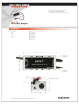
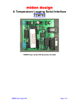
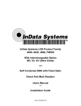
PowerPower-Link
User Manual
Rev.: 000101
This user manual contains instructions for installing the Power-Link, setting up the operating
characteristics with AddressNet™ software and a list of the most common mistakes made
when installing the Power-Link.
Contents
Contents.......................................................…………………………………………………………2
Power-Link Overview......................................……………..………………………………………...4
Common Mistakes........................................……………………………………………………….. 5
Cables are Wrong .....................................……………………………………………. 5
Handshaking – Use it or lose data .............…………………………………………… 5
Addressing...............................................……………………………………………… 5
Address Listing .........................................…………………………………………….. 5
ACK/NAK – RF Handshaking ...................…………………………………………….. 5
Using Windows 95 and Hyper Terminal…………………….………………………….. 5
Getting Best RF Reception ..........................…………………………………………………. ……. 6
Interference Noise Sources ......................…………………………………… ……. 6
Cables........................................................………………… …………………………………….... 6
Long Cables..............................………………………………………………….……... 6
“Straight” Cable Wiring Diagram..............……………………………………………... 7
“Null” Cable Wiring Diagram....................……………………………………………... 7
Wiring – Power-Link .................................…………………………………………………….......... 8
Power-Link Pin-Out Chart. .........................………………………………………….... 8
DSR/DTR Conversion to RTS/CTS ......…………………………………………… .... 8
Power Requirements ..................................……………………………………………………….... 8
No Power Supply Required ...................…………………………………………….... 8
Signals Used for Power......................……………………………………………........ 8
Using Logic Level Signals ................…………………………………………….......... 9
“Home Brew” Drive Signals ........……………………………………………............... 9
External Power..................................……………………………………………......... 9
Handshaking – You Need It ………………………………………………………………………….. 9
Hardware vs. Software Handshaking..……………………………………………....... 9
Data Loss.......................................……………………………………………............ 10
Data Size ............................................…………………………………………………………........ 10
Smallest Data Size.............……………………………………………........................ 10
Largest Data File Size...........……………………………………………..................... 10
Error Control ARQ (ACK/NAK) ……………………………..………………………………..............10
Data Integrity.................................………………………………………………………….............. 11
Addressing ...................................……………………………..............…………………………….11
Unit Address and Target Address...........……………………………………………....11
Dynamic Addressing by “First Byte” in Data Packet ……………..………………......11
Dynamic Addressing by Reprogramming ……………………………………..............12
LED Light Indicators .....................……………………………………………….………................. 12
AddressNet ™ Set Up Software Overview………………..…………………………….................. 13
Serial Port Settings.....................…………………………………………………………................. 13
RF Serial Settings................................…………………………………………………………........ 13
Handshaking ............................…………………………………………………………................... 14
Addressing ...................................…………………………………………………………............... 14
Error Correction............................…………………………………………………………............... 15
Misc. ...........................………………………………………………………….......……...................15
Test Center ...............................................…………………………………………………………...15
Detection Options......................................………………………………………………………….. 15
Batch Programming.............................…………………………………………………………........ 16
Using Power-Link with Microsoft Windows 95 and Hyper Terminal …………………………........16
FCC Notice...................................…………………………………………………………............... 17
Declaration of Conformity ...............………………………………………………………............... 18
WARRANTY INFORMATION .............………………………………………………………........... 18
SOFTWARE LICENSE AGREEMENT...……………………………………………………….........20
Technical Support ............................…………………………………………………………...........20
Power-Link DB 9 Pin Out………………………………………………………………….. Appendix A
Scanner Configurations and Cables ……………………………………………………….Appendix B
3
Power-Link
Overview_____________________________
The Power-Link is a serial data radio interface with an interchangeable, rechargeable battery to
allow powering of 5 volt devices such as barcode scanners (CCD, Wand, or Laser) as well as a
wide variety of other data collection devices. This powered radio interface allows cordless
powered interface of devices that previously needed very long cables to get the input device to
where the source of the data occurs.
Weighting just 17 ounces the Power-Link Transceiver is a cost effective means of transferring
data to and from any other RS-232 Serial equipped devices via the 900 MHz ISM band. No
license is required.
Each transceiver is unit addressable, so up to 254 remotes can communicate with a single host
or with each other.
The UniLink is the Power-Link’s “receiving station” and is a parasitically powered device that
requires only a few milliwatts of power from any output signal on any RS-232 port. There are no
batteries required in the Unilink transceiver.
The Power-Link opens up an entire new set of serial data communications applications. Batch
applications can now be easily converted to real-time wireless with either no changes or only
minor programming changes. By using the Power-Link, serial scanners up to 400 feet away can
input data from barcode labels, Pick Lists, Shippers, Invoices, Receipts and Bill of Lading.
The Power-Link can be attached to portable barcode scanners for a very low cost solution to
wireless scanning. Any portable device with a serial port can now be brought online with access
to a host in real time.
The Power-Link and UniLink comes with AddressNet ™ Software. AddressNet™ is an easy to
use Windows 95/98 compatible utility with a GUI interface that allows the user to modify data
format, baud rate, handshaking protocol and the transmit and receive address of each
transceiver. The user simply points and clicks to configure the transceiver’s sophisticated
capabilities that are then retained permanently within the Power-Link non-volatile memory.
Common
Mistakes_______________________________
Things That Go Wrong
Read this section to avoid some of the most common mistakes in setting up RF serial
transceivers.
4
Cables are Wrong
The Power-Link is pre-wired to attach directly to a PC/Laptop using a “Null Modem” or “Lap Link”
setup cable. But when a Unilink is attached to a PC, it requires a “straight” cable, and
when a Serial Printer is attached to the Power-Link, it also requires a “straight” cable as well. A
“Null” cross cable/adapter may only be required when connecting to some peripherals.
Use InData’s Serial Interface test kit to aid in trouble shooting interface problems. Contact your
local reseller to order.
Handshaking – Use it or lose data
Unless the data being transmitted is smaller than 40 bytes and occurs infrequently, handshaking
is required or data will be lost. Handshaking can halt data flow from its host while the radios are
processing the data. RTS/CTS hardware handshaking is the preferred method to use instead of
software handshaking XON/XOF.
This is especially true when using InData Systems Active Repeater system, as all data is
transmitted on the same frequency and needs to pause during the re-transmission.
Programmers Advanced Tip:
Even with handshaking activated, the software program you write needs to frequently poll for
handshaking activity, not just at the end of big blocks of data.
Addressing
If more than one pair of Power-Links/Unilinks is to be used within range of each other, each
needs to have A unique address. Addresses can be from 1 to 255. This address is assigned
using the AddressNet™ software that came with the Power-Link. See “Setting Addresses”
section.
Address Listing
When assigning an address to a Power-Link or Unilinke, be sure to write it down in pencil on the
label provided. It is also handy to make a list to keep on file. If you need to find what address
the Power-Link is set for, use the AddressNet™ software to interrogate the Power-Link or
Unilink.
ACK/NAK – RF Handshaking
Do not disable this feature! ACK/NAK allows a receiving unit to request a re-send of the data if it
is determined to be corrupted. This option is enabled as a factory default, but can be disabled
using check-off box in the AddressNet™ software.
Using Windows 95 and Hyper Terminal
Turn the FIFOs OFF to prevent buffer overflow. See Appendix A section for more details.
5
Getting Best RF
Reception________________________
Many things can interfere with radio signals. Some materials can absorb radio signals and
some other reflect it. As the waves are reflected, or absorbed, at any given point of convergence
they may cancel each other out if they are out of phase. This effect is called “multi-path fading”.
So if the Power-Link is having spotty reception in one area, moving a few feet can make a great
difference.
User of an InData extension kit, enables you to place the Unilink base transceiver at an optimal
location.
Interference Noise Sources
Other electronic devices can create radio interference. Computer monitors are notorious
generators of radiated noise, so don’t mount the Unilink base transceiver to the side of a
monitor. Laptop PCs displays may also be electrically noisy.
Use a long serial cable to allow positioning the Unilink as needed away from these types of
problem areas and to maximize range and reception. Using a long cable in stationary
installations, it is possible to suspend a UniLink from the ceiling, effectively getting it above many
of the reflective or absorptive materials.
Cables
Long Cables
Excellent power efficiency allows the Unilink to be placed at the end of a long extension cable.
For cable lengths over one hundred feet (100’), a wire gauge of at least 22 gauge is
recommended. Provide inputs Rd (pin3), CTS (pin 7), and DSR (pin4) signals as well as the Td
(pin 2) and Ground (pin 5) to minimize voltage loss to the unit.
Before installing a long cable extension, test the Unilink with the full length of the intended cable
to ensure that it will work before permanently installing the cable. Place the Unilink at the end of
the cable spool and plug the other end into the device that will be using it. If the Unilink works
when attached to the end of the long cable, then there should be no problem once the cable is
fully installed.
Straight Cable vs. Null Cross Cable A “Straight” cable has no wire signals crossing. Pin #1 at
one end of the cable connects to Pin #1 on the other end of the cable, pin #2 connects to pin#2,
etc.
25,50, and 100 foot serial cables are available through your local InData Systems Reseller
6
“Straight” Cable Wiring Diagram for a nine pin cable.
1 ---------------------------------------------- 1
2 ---------------------------------------------- 2
3 ---------------------------------------------- 3
4 ---------------------------------------------- 4
5 ---------------------------------------------- 5
6 ---------------------------------------------- 6
7 ---------------------------------------------- 7
8 ---------------------------------------------- 8
9 ---------------------------------------------- 9
The Null Cross cable is for connecting to serial devices that are wired the same, such as a
computer to another computer. The Null cable crosses the Rd receive and Td transmit data
lines,
the RTS and CTS lines, and DTR and DSR lines.
“Null” Cable Wiring Diagram for a nine pin cable
1 --------------------------------------------- 1
2 --------------------------------------------- (3)
3 --------------------------------------------- (2)
4 --------------------------------------------- (6)
5 --------------------------------------------- 5
6 --------------------------------------------- (4)
7 --------------------------------------------- (8)
8 --------------------------------------------- (7)
9 --------------------------------------------- 9
If a Null Cross cable is not available, a straight cable can be changed into a Null cable by way of
a Null Adapter. A Null Adapter plugs into the cable end and contains the necessary wire
crossings. See the “Accessories” section for Null adapters.
Keep in mind that the UniLink (Base Unit) receives data on pin #3 and it outputs data on pin #2.
If the host device being used also outputs data on pin 2 then a Null Cross is required.
A Power-Link has a male DB-9 which outputs data on pin #3. Devices that are designed to plug
into the male DB-9 on a PC are properly pinned to plug into the Power-Link portable unit.
Regulated 5 volts DC is provided on pin #9. If you are unable to get a cable for your scanner or
protable device to use this powered pin you may obtain a power adapter cable from InData
Systems Reseller – For common barcode scanner interface cables see Appendix H
7
Wiring – Power-link____________________________
Power-Link Pin-Out Chart.
Male 9-pin D-sub connector.
Pin Number
1
2
3
4
5
6
7
8
9
Signal Name
Power-Link Input / output
Not Used
Input
Output
Not Used
Ground
Not Used
Output
Input
+ 5 +7.2 Volts
Receive Data
Transmit Data
Ground
Ready to Send
Clear to Send
+ 5 Volts
Power Requirements
The Power-Link utilizes a rechargeable “Lithium” battery the battery is equivalent to a Sony NPF550 camcorder battery. Both the battery and spare chargers are available from your InData
Systems reseller. The battery can last up to 100 hours or more depending on the device being
powered by the Power-Link.
No Power Supply Required for UniLink base unit.
The Unilink’s Radio is able to derive its power parasitically from the RS-232 signals of the host
device to which it is attached, much the same way as the mouse on a computer.
Signals Used for Power
The Unilink’s Radio extracts power from RS-232 B/C signals. The three signals that provide
power to the Unilink are RD Pin #3, CTS Pin #7, and DSR Pin #4.
The signals can be any polarity and in continuous rapid transition at the maximum baud rate.
8
Using Logic Level Signals
Pseudo RS-232 signal transitioning from 0 to +5VDC are acceptable. As long as the drive
circuit is compliant with published RS-232 B/C guidelines including meeting voltage, high output
impedance, and current limitations the Power-Link should function properly.
“Home Brew” Drive Signals
Non-compliant drive circuitry capable of delivering large current at high
voltages may cause the Power-Link or your circuitry to fail.
Non-compliant, high voltage, high current, low impedance drive signals should never
exceed +/-6.0VDC.
External Power
The Power-Linke is designed to power external devices with +5 VDC on pin 9 and ground on pin
5. It is capable of powering devices up to 250 ma continuous current or up to 1 amp in low duty
cycle applications. Consult your InData Reseller to determine if your scanner or device will work
properly.
Handshaking – You Need It
Handshaking allows one serial device to signal another when it is necessary to temporarily halt
the flow of data to prevent buffer overflow. This is a very important function of all serial
communication devices.
The Power-Link has a transmit buffer that can hold up to 40 bytes of data. If the data packet
being sent is larger than that, or if it is smaller but very frequent, then handshaking must be used
to prevent buffer overflow and subsequent data loss. The rule is, when in doubt use
handshaking.
Hardware vs. Software Handshaking
Hardware handshaking RTS/CTS is faster and more efficient than software handshaking using
XON/XOFF. Software handshaking is not preferred and should not be used unless there is no
alternative.
9
Data Loss
If data loss is evident at the receiving Power-Link or Unilink, it generally indicates that
handshaking at the transmitting unit is not functioning properly. The most common cause of this
failure mode is not having handshaking turned on within the host (sending) device. This means
that the Power-Link/Unilink is ordering the data feed from its Host to stop, but the host is not
responding and keeps sending data. The obvious result will be overflow of the buffer with
subsequent data loss.
The Power-Link is programmed so that the hardware handshake signal is sent early enough to
allow for response delay from the host. In software handshaking mode the Power-Link sends the
XON/XOF software handshake request even earlier since there is a greater response delay from
the host.
Data
Size_______________________________________
Smallest Data Size
The Power-Link can transmit data packets as small as one byte.
Largest Data File Size
There is no upper limit to the size of the file to be transmitted. However, keep in mind that if a
unit is transmitting a large file it will be “hogging” the channel and other units will not be able to
transmit until it is done.
When the InData Systems Active Repeater is used throughput will be drastically reduced if long
strings of data are transmitted in either direction. See Section “Active Repeater” on page 15
Error Control
ARQ
(ACK/NAK)_________________________________
A sophisticated and highly reliable form of Error Control employed in the Power-Link/Unilink is
called ARQ (Automatic Retry Request), using ACK/NAK closed loop feedback from the Target
Power-Link or Unilink. When a data packet is received by the Target unit, it will send back either
an ACK or a NAK to the Initiator. An ACK tells the Initiator that the data was good and to send
the next data packet. A NAK tells the Initiator that the data was corrupted and to transmit it
again. If neither ACK or NAK is returned from the target, the Initiator will automatically retry to
send the unacknowledged packet. The number of retries possible is from one to fourteen and
this value is programmed using he AddressNet™ software. It is advisable to set a higher retry
count for units that are further apart.
10
Data Integrity__________________________________
The transmitting Power-Link packetizes data into blocks for transmission. The receiving unit will
not output this packet to its host unless it is received 100% intact. If the ACK/NAK retry count is
exceeded before the data is received uncorrupted, the data will be lost.
To improve data integrity, the number of retry attempts can be increased, or the programmer
could create a special program. The program would have to incorporate a check sum (add all
the bytes in your data file in ASCII) or a CRC as part of the transmitted data. If the received data
does not match the check sum, the program should request that it be resent. This is similar to
ACK/NAK but on a larger file-wide scale.
Addressing____________________________________
The Power-Link provides a way for each unit to differentiate itself from others by having a unique
address. There is a Unit Address and a Target Address. Having a unique address allows the unit
to know when data is being sent to it and to which device to send data. This allows multiple units
to cohabit the same reception area and not have the data corrupted. Addresses can be from 1 to
255.
Unit Address and Target Address
The Unit Address is the address of that particular unit. The Target Address is the address of the
unit that this Power-Link will target any transmissions. Only a unit with that target address will
respond to transmissions from this unit.
In general, do not allow two units to have the same Unit address. The only circumstance in
which duplicate address might be acceptable is if those two units were the only two units within
the area, and would never be targeted by other units.
Besides one-to-one addressing, the Power-Link has the ability to do one-to-many addressing.
This can be done two ways, by dynamic addressing and by address reprogramming on the fly.
Dynamic Addressing by “First Byte” in Data Packet
Dynamic addressing is activated by using the AddressNet™ software. Once activated, the
Power-Link will take the first byte of a data stream and make that the Target address to send to.
This will continue to be the target address until data stops and the buffer empties out. Once the
buffer empties, the Link again watches for the first byte of data and uses that value as the “new”
target address.
11
Dynamic Addressing by Reprogramming
Dynamic addressing by reprogramming on the fly involves sending a special character sequence
(referred to as the “Gatekeeper String”) to the unit that tells it to change its target address to the
supplied address.
It is important that dynamic addressing not be mistakenly enabled in AddressNet™ when using
this form of addressing.
The Gatekeeper character string to send is:
(ASCII) p ` P @ 0 SP H <address>
or (Hex) 70 60 50 40 30 20 48 <address>.
Remember that the address is not entered in ASCII, it is the integer value of the character used
(see Appendix A for ASCII charts).
INCORRECT
CORRECT
ASCII A
p`P@0 H65
p`P@0 HA
=
INTEGER 65
If the correct value in this example were sent to the Power-Link it would change its target
address to 65 because 65 is the integer value of an ASCII A. In this example the ASCII “A” is
used because it is a “visible” character which can be viewed by ASCII communications
programs. Some
characters in ASCII such as “escape” (ESC) can not be seen on a monitor. The full ASCII
character set can be used from 1 to 254.
LED Light Indicators____________________________
The Power-Link has two light emitting diodes (LED’s) for diagnostic purposes.
If either LED is flashing, then the Power-Link is being supplied with enough power to operate
properly.
If the transmit LED is flashing, the unit is transmitting data or ACK/NAK’ing back to an
Initiator in response to received data.
If the receive LED is flashing, it means that a Power-Link within range is transmitting (but not
necessarily to this unit’s address) and that the unit is detecting the transmission.
If both LED’s are flashing, then the unit is both transmitting and receiving to/from another unit.
12
AddressNet ™
Set Up Software Overview_______________________
AddressNet™ is a software utility that enables communication with a Power-Link. It allows for
testing, troubleshooting, and setup of the 900MHz Radio Frequency (RF) device. AddressNet™
is a Windows 95 graphical user interface (GUI) program and does not run on older versions of
Windows nor Windows NT.
Accessing the different functions of AddressNet is done through the buttons which are located
on the left side of the main program window. They are in order from top to bottom:
Serial Port Settings
RF Serial Settings
Handshaking
Addressing
Error Correction
Misc.
Test Center
Detection Options
Batch Programming
Serial Port Settings_____________________________
Changes to the computer serial port can be made from here. Available changes are baud, data
bits, parity, stop bits, and COM Port (serial port). Setting these correctly will allow
communication with the RF unit.
The serial port (also called a COM port) is where the Power-Link will be attached to the
computer for use. AddressNet currently supports up to six serial ports (COM 1 through COM 6).
When changes are made to the serial settings ensure that the “Apply button” is pressed before
leaving for a different area of the program. If not the changes will be discarded leaving the
settings unchanged.
RF Serial Settings______________________________
The RF Serial Settings area is identical to the Serial Port Settings area except there is no COM
port selection. Baud, data bits, parity, and stop bits are all available for modification.
Options for the RF unit will not function until a unit is detected on the selected serial port. This
applies to all area of the AddressNet program.
Any time a change is made to the RF units settings the “Apply button” for that area must be
clicked or the changes will be discarded leaving the settings unchanged.
13
Handshaking__________________________________
Handshaking controls the flow of data between the host and the RF unit. When a device buffer
(data storage area) gets full and is no longer able to accept data using handshaking, it can
signal the other to stop sending until there is more room.
Handshaking is extremely important, particularly when sending larger blocks of data to the RF
unit for transmission. RTS/CTS is the standard for hardware handshaking and is the preferred
technique to use with the Power-Link. XON/XOFF is the standard for software handshaking. It
should only be used when RTS/CTS is unavailable.
Addressing____________________________________
This area is for changing the various addressing options for the Power-Link unit. The unit
address, target address, address pass through, and dynamic addressing can all be
altered/activated here.
The unit address and the target address are user assignable from 1 to 255. The target address
can also be set to dynamic. In dynamic mode, the target address is changed “on the fly”. The
first byte in a data stream received by a unit in dynamic configuration will be stripped from the
data and used as the target address. This address is permanent until it is set again. A new
address will only take effect when the buffer is allowed to empty.
Pass through of an initiator address to the host allows for the receiving application to process
received data based upon which unit sent it. A unit in this configuration will insert its unit address
to the beginning of the incoming data stream so that the receiving application can process the
data following based upon where it came from. The unit address will only be applied if the buffer
is empty.
As with all areas, when changes are made, ensure that the “Apply button” is pressed before
leaving for a different area of the program. If not, the changes will be discarded leaving the
settings unchanged.
14
Error Correction________________________________
The Error Correction area allows the ACK/NAK options for Power-Link unit to be altered.
ACK/NAK is a form of handshaking and it is recommended that it be enabled. Longer distance
units should use a higher retry amount.
When using this form of handshaking, the receiving unit, upon detection of bad data, is able
to request that the host retry to send the data. The unit will ask again for the correct data as
many times as is specified in the retry box. Valid retries are from 1 to 15.
Misc._________________________________________
Once a unit is detected, the Misc. area will show the firmware revision number and the unit serial
number.
Test Center____________________________________
A Power-Link unit’s settings can be tested using this area. The box on the left is for transmission
and the one on the right is for reception. All data typed or pasted into the “Transmit” box will be
sent out of the computer serial port to the Power-Link for transmission. All data received by the
serial port will be placed into the “Received” box.
In terminal emulation, the unit will transmit all data that is sent to it through the serial port. In
echo mode, the unit will send the received character back to the serial port. This received data
will be placed into the receive box. Echo mode allows testing of singular units.
Detection Options______________________________
This area provides a means to detect the Power-Link unit attached to the computer. Detection
can occur at the current serial port settings, or the unit can be auto-detected.
Auto-detect is a feature that can be used to determine the settings of unit if they are forgotten
or changed. Auto-detect systematically queries through all possible serial port settings until a
valid response is received. An attempt is then made to download the unit’s current setup.
Batch Programming____________________________
This area is used to program the settings multiple units and to create the files need to perform
these tasks.
When creating a programming file you will be shown a complete list of the current settings.
These will be saved to the disk.
To batch program units, first select a valid file. Then hit the program button. The file only needs
to be selected once and it will be reused each time the program button is pressed.
15
Active Repeater________________________________
In applications where the area of usage may be farther than reliable communication can be
maintained it may be desirable to use InData System’s Active Repeater. This is simply the
connecting of the base Unilink receiver with another Power-Link and using it’s mate Unilink on
the PC or other receiving serial device – See figure below
Appendix A
Using Power-Link with Microsoft Windows 95 and
Hyper Terminal________________________________
Turn the FIFOs OFF – The most common problem with using the Windows 95 Hyper
Terminal communications program is forgetting to turn the FIFO buffers OFF for serial interface
of the PC.
Un-check the “Use FIFO buffers” box within the Advanced Port Settings window of Hyper
Terminal set up program.
A detailed Applications Note on setting up Windows 95 Hyper Terminal is available from
the Technical Support web site listed in the Appendix.
16
Appendix C
FCC Notice____________________________________
This device complies with Part 15 of the FCC rules. Operation is subject to the following two
conditions.
1.This device may not cause harmful
interference, and
2. This device must not accept any interference
received, including interference that may cause undesired operation.
Instructions to the User
This equipment has been tested and found to comply within the limits for a Class B digital
device, pursuant to Part 15 of the FCC Rules. These limits are designed to provide reasonable
protection against harmful interference in a residential installation. This equipment generates,
uses, and can radiate radio frequency energy and if not installed and used in accordance with
the instructions, may cause harmful interference to radio communications. However, there is no
guarantee that interference will not occur in a particular installation. If this equipment does cause
harmful interference to radio or television reception, which can be determined by turning the
equipment off and on, the user is encouraged to try and correct the interference by one or more
of the following measures:
1. Reorient or relocate the receiving antenna
2. Increase the separation between the equipment and receiver.
3. Connect the equipment into an outlet on a circuit different from that to which the
receiver is connected.
4. Consult the dealer or an experienced radio technician for help.
In order to maintain compliance with FCC regulations, shielded cables must be used with this
equipment. Operation with non-approved equipment of unshielded cables is likely to result in
interference to radio and TV reception. The user is cautioned that changes and modifications are
forbidden to be made to this equipment and could void the user’s authority to operate this
equipment.
17
Appendix D
Declaration of Conformity________________________
Equipment Type
Trade name (s)
Model Number
Compliance Test Report Number
Compliance Test Report Date
Responsible Party (U.S.A.)
Address
RF Data Radio
Power-Link, RF Link
ML916NBP
B71120D1
26 November 1997
Wireless Mountain Corp.
5132 Bolsa Ave, #102
Huntington Beach
CA 92649 USA
This equipment has been tested and found to comply with the limits for a Class B digital device,
pursuant to Part 15 of the FCC rules. These limits are designed to provide reasonable protection
against harmful interference in a residential installation. This equipment generates, uses and can
radiate radio frequency energy and, if not installed and used in accordance with the instructions,
may cause harmful interference to radio communications. However, there is no guarantee that
interference will not occur in a particular installation.
If the Unit does cause harmful interference to radio or television reception, please refer to your
user’s manual for instructions on correcting the problem.
I, the undersigned, hereby declare that the equipment specified above conforms to the above
requirements.
Name:
David Culp
Position:
Vice President of Engineering
Date:
29 January 1998
Place:
Huntington Beach CA USA
18
Appendix E
WARRANTY INFORMATION______________________
Effective January 1, 1999
Wireless Mountain and its design and manufacturing facility’s sole obligation under this
warranty shall be to furnish parts and labor for the repair or replacement of products
found to be defective in material or workmanship during the warranty period.
As a condition of this warranty, the user must: (a) obtain an Wireless Mountain Return
Authorization for the product, device or subassembly(s); (b) ship the device, transportation
prepaid to the authorized service location; and (c) include with the Product, device or
subassembly(s) a written description of the claimed defect. Items returned shall be packaged in
the original packaging and shipping container or comparable container. In the event equipment
is not so packaged or if shipping damage is evident, it will not be accepted for service under
warranty. Surface transportation charges for the return of the product shall be paid by Wireless
Mountain within the 48 contiguous states and the District of Columbia. Customer shall pay
shipping costs, customs clearance, and other related charges outside the designated area. If
Wireless Mountain determines that the items returned for warranty service or replacement is not
defective as herein defined, USER shall pay all costs of handling and transportation.
Warranty Exclusions and Conditions
The above warranties are in lieu of all other warranties, expressed or implied, oral or written,
statutory or otherwise, including an implied warranty of merchantability or fitness for a
particular purpose.
Wireless Mountain and its design and manufacturing facilities shall not be responsible for the
specific application to which any Products are applied, including but not limited to compatibility
with other equipment.
All statements, technical information and recommendations relating to Wireless Mountain
Products are based upon tests believed to be reliable but do not constitute a guarantee or
warranty.
WIRELESS MOUNTAIN AND ITS DESIGN AND MANUFACTURING FACILITIES SHALL
NOT, UNDER ANY CIRCUMSTANCES WHATSOEVER, BE LIABLE TO BUYER OR
ANY OTHER PARTY FOR LOST PROFITS, DIMINUTION OF GOOD WILL OR ANY OTHER
SPECIAL OR CONSEQUENTIAL DAMAGES WHATSOEVER WITH RESPECT TO ANY
CLAIM HEREUNDER. IN ADDITION, WIRELESS MOUNTAIN, INCLUDING ITS DESIGN AND
MANUFACTURING FACILITIES, LIABILITY FOR WARRANTY CLAIMS SHALL NOT, IN ANY
EVENT, EXCEED THE INVOICE PRICE OF THE PRODUCT CLAIMED DEFECTIVE, NOR
SHALL WIRELESS MOUNTAIN AND ITS DESIGN AND MANUFACTURING FACILITIES BE
LIABLE FOR DELAYS IN REPLACEMENT OR REPAIR OF PRODUCTS.
No salesperson, representative or agent of Wireless Mountain Corporation and design and
manufacturing facilities is authorized to make any guarantee, warranty, or representation in
addition to the forgoing warranty.
NO WAIVER, ALTERATION, ADDITION, OR MODIFICATION OF THE FOREGOING
WARRANTIES SHALL BE VALID UNLESS MADE IN WRITING AND SIGNED BY AN
EXECUTIVE OFFICER OF WIRELESS MOUNTAIN
19
Appendix F
SOFTWARE LICENSE AGREEMENT_______________
Software and documentation provided by Wireless Mountain and it’s affiliates are protected by
the United States copyright law and international treaty, and therefore you must treat them like a
book, with the exception that you make copies of the software to protect yourself against loss of
the original.
Your right to use the software and documentation as described below is non-exclusive and nontransferable. Wireless Mountain retains ownership of the software and documentation and all
other rights, title and interest. The software and documentation may be used by any number of
people, and the software may be freely moved from one computer to another.
Wireless Mountain warrants the software diskette to be free of defects in material and
workmanship for a period of 60 days from the date of purchase. In the event of notification within
the warranty period of defects in material and workmanship, Wireless Mountain will replace the
defective diskette or documentation. Wireless Mountain specifically disclaims all other
warranties, express or implied, including but not limited to implied warranties of merchantability
and fitness for a particular purpose.
IN NO EVENT WILL INDATA SYSETMS OR ITS’ DESIGN AND MANUFACTURING
FACILITIES BE LIABLE FOR LOST PROFITS, LOST DATA, OR ANY OTHER INCIDENTAL
OR CONSEQUENTIAL DAMAGES CAUSED BY ABUSE OR MISAPPLICATION OF THE
SOFTWARE OR BY ITS USE IN VIOLATION OF THE U.S. COPYRIGHT LAW OR
INTERNATIONAL TREATY.
20
Appendix G
Power-Link Pin Out
Pin
1
2
3
4
5
6
7
8
9
Name
RX
TX
GND
RTS
CTS
+5
Direction
1
5
6
9
Description
Not Used
Receive Data
Transmit Data
Not Used
System Ground
Not Used
Request to Send
Clear to Send
+ 5 Volts (or 7.2 Volts unregulated on specially configured models)
Using a standard Lap-Link cable you can configure the Power-Link with AddressNet software.
KEY
In
Out
21
Appendix H
Common Scanner Setups
Welch Allyn 3800
Cable required
InData Part Number – WA-42203758-03
Setup
Page
1-4
2-11
2-12
3-4
Back Cover
Manual Rev E
Scan
RS-232 Interface
8 Data, 1 Stop, Parity None
RTS/CTS On
Low Power Time Out
1, 0, Save
The scanner should now be setup to use the Power-Link
Welch Allyn 54/5700
Cable required
InData Part Number – WA-42203758-03
Setup
Page
1-9
1-15
2-12
2-12
Manual Rev H
Scan
RS-232 Interface
Switched Power (Low Power) Mode
8 Data, 1 Stop
Parity None
The scanner should now be setup to use the Power-Link
Symbol 3203
Cables required
InData Part Numbers – SY-25-15072-01 and
Setup
Manual Rev A
Page
Scan
3-4
Set RS-232C Host
3-28
9600
3-29
NONE
3-31
RTS/CTS
3-33
1 STOP BIT
3-34
8-BIT
3-35
LOW POWER
The scanner should now be setup to use the Power-Link