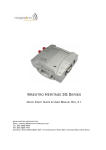
Download Maestro E200 Series Quick Start Guide User Manual
Transcript
Maestro E200 Series Quick Start Guide User Manual Version 1.1 www.maestro-wireless.com Email: [email protected] Tel: (+852) 2869 0688 Fax: (+852) 2525 4701 Address: Room 3603-3609, 36/F, 118 Connaught Road West, Sheung Wan, Hong Kong 1 Revision History Version 1 1.1 2 Date 9 April 2014 21 July 2014 Details First issue E200 V1.1 Combined H/W and S/W manual Originated by Samuel Chereau Alok Kelkar & Akshay Natu Reviewed by Shripad Nawalkar Confidential, the whole document is the sole property of Maestro Wireless Solutions ltd. [email protected] This manual is written without any warranty. Maestro Wireless Solutions Ltd. reserves the right to modify or improve the product and its accessories which can also be withdrawn without prior notice. Besides, our company stresses the fact that the performance of the product as well as accessories depends not only on the proper conditions of use, but also on the environment around the places of use. Maestro Wireless Solutions Ltd. assumes no liability for damage incurred directly or indirectly from errors, omissions or discrepancies between the tracker and the manual. This software, solution or application is provided on an "as is" basis. No warranty whether expressed or implied is given by Maestro Wireless Solutions Ltd. in relation to this software, solution or application. User shall assume the entire risk of using or relying on this software, solution, application. In no event will Maestro Wireless Solutions Ltd. be liable for any loss or damage including without limitation, indirect or consequential loss, damage, or any loss, damage whatsoever arising from loss of data or profit arising out of, or in connection with, the use of this software, application or solution. Every effort is made to keep the software, application or solution up and running smoothly. However, Maestro Wireless Solutions Ltd. takes no responsibility for, and will not be liable for, the software, application or solution being temporarily unavailable due to technical issues beyond our control. The above terms and conditions are subject to change without prior notice. The present use of this software, application or solution implies the user approves and understands all the above terms and conditions. Confidential, the whole document is the sole property of Maestro Wireless Solutions ltd. [email protected] 3 Table of Contents 1 Revision History .................................................................................................................................... 2 2 Safety Precautions ................................................................................................................................ 7 2.1 General precautions...................................................................................................................... 7 2.2 Using the router in vehicle ............................................................................................................ 7 2.3 Protecting your router .................................................................................................................. 7 3 Specifications ........................................................................................................................................ 8 3.1 Cellular .......................................................................................................................................... 8 3.2 Linux processor ............................................................................................................................. 8 3.3 Power supply requirements .......................................................................................................... 8 3.4 Typical current consumption ........................................................................................................ 8 3.5 Interfaces ...................................................................................................................................... 8 3.6 Dimensions.................................................................................................................................... 9 3.7 Temperature range ....................................................................................................................... 9 3.8 Performance data ......................................................................................................................... 9 3.9 Core features................................................................................................................................. 9 3.10 Front label ................................................................................................................................... 10 3.11 Back label .................................................................................................................................... 10 3.12 Packing ........................................................................................................................................ 10 4 Equipment Description ....................................................................................................................... 11 4.1 Interfaces .................................................................................................................................... 11 4.2 Status indicator ........................................................................................................................... 11 4.3 SMA female antenna connector (Cellular and GPS) ................................................................... 12 4.4 RP-SMA female antenna connector (Wi-Fi) ................................................................................ 12 4.5 8P8C RJ45 connector (WAN/LAN) ............................................................................................... 12 4.6 Reset button ............................................................................................................................... 12 4.7 4-pin Micro-Fit Molex connector (Power and input/output) ..................................................... 12 5 Hardware Installation ......................................................................................................................... 13 5.1 5.2 5.3 5.4 5.5 5.6 5.7 5.8 4 Mounting the router ................................................................................................................... 13 Installing the SIM card ................................................................................................................ 13 Connecting the external antennas (SMA type) ........................................................................... 13 Connecting the router to your existing WAN access .................................................................. 13 Connecting the router to your device / LAN ............................................................................... 13 Connecting the DC power supply................................................................................................ 13 Digital input/output wiring diagrams ......................................................................................... 14 Optional accessories ................................................................................................................... 15 Confidential, the whole document is the sole property of Maestro Wireless Solutions ltd. [email protected] 6 Default settings ................................................................................................................................... 15 7 E200 Series Router configuration and Usage...................................................................................... 16 7.1 Quick Setup ................................................................................................................................. 19 7.2 Op Mode ..................................................................................................................................... 24 7.3 Network ...................................................................................................................................... 26 7.3.1 LAN ...................................................................................................................................... 26 7.3.2 WAN .................................................................................................................................... 28 7.3.3 Cellular ................................................................................................................................ 29 7.3.4 Routing ................................................................................................................................ 30 7.3.5 DHCP Server ........................................................................................................................ 31 7.3.6 DHCP Clients........................................................................................................................ 32 7.3.7 MAC Clone........................................................................................................................... 32 7.4 Wireless....................................................................................................................................... 33 7.4.1 Basic .................................................................................................................................... 34 7.4.2 Advanced............................................................................................................................. 35 7.4.3 Security ............................................................................................................................... 36 7.4.4 WDS ..................................................................................................................................... 37 7.5 Firewall ........................................................................................................................................ 41 7.5.1 MAC/IP Filtering .................................................................................................................. 41 7.5.2 Port Forwarding .................................................................................................................. 43 7.5.3 MAC/IP bind ........................................................................................................................ 44 7.5.4 DMZ ..................................................................................................................................... 45 7.5.5 Content ............................................................................................................................... 46 7.5.6 QoS ...................................................................................................................................... 47 7.5.7 Security ............................................................................................................................... 48 7.6 VPN.............................................................................................................................................. 49 7.7 Management ............................................................................................................................... 50 7.7.1 Configuration ...................................................................................................................... 51 7.7.2 Settings................................................................................................................................ 52 7.7.3 Firmware ............................................................................................................................. 52 7.7.4 Statistics .............................................................................................................................. 53 7.7.5 Syslog .................................................................................................................................. 54 7.7.6 Reboot ................................................................................................................................. 55 Confidential, the whole document is the sole property of Maestro Wireless Solutions ltd. [email protected] 5 7.8 M2M Apps ................................................................................................................................... 57 7.8.1 Scheduled reboot ................................................................................................................ 57 8 6 7.8.2 Ping...................................................................................................................................... 58 7.8.3 DynDNS ............................................................................................................................... 59 7.8.4 SMS ..................................................................................................................................... 60 7.8.5 Events/ I/O Control ............................................................................................................. 60 7.8.6 Transparent ......................................................................................................................... 61 7.8.7 GPS ...................................................................................................................................... 62 Appendix A: List OF abbreviations ...................................................................................................... 63 Confidential, the whole document is the sole property of Maestro Wireless Solutions ltd. [email protected] 2 Safety Precautions 2.1 General precautions The router generates radio frequency (RF) power. When using the router care must be taken on safety issues related to RF interference as well as regulations of RF equipment. Do not use the router in aircraft, hospitals, petrol stations or in places where using GSM products is prohibited. Be sure that the router will not be interfering with nearby equipment. For example: pacemakers or medical equipment. The antenna of the router should be away from computers, office equipment, home appliance, etc. Always keep the router with minimum safety distance of 26.6cm or more from human body. Do not put the antenna inside metallic box, containers, etc. 2.2 Using the router in vehicle Check for any regulation or law authorizing the use of GSM in vehicle in your country before installing the router. Install the router by qualified personnel. Consult your vehicle dealer for any possible interference of electronic parts by the router. Be careful when the router is powered by the vehicle’s main battery. The battery may be drained after extended period. 2.3 Protecting your router To ensure error-free usage, please install and operate your router with care. Do remember the following: Do not expose the router to extreme conditions such as high humidity/rain, high temperatures, direct sunlight, caustic/harsh chemicals, dust, or water. Do not try to disassemble or modify the router. There is no user serviceable part inside. The warranty would be void in case of tampering. Do not drop, hit or shake the router. Do not use the router under extreme vibrating conditions. Do not pull the power supply cable. Please attach or detach it by holding the connector after switching off the supply. Connect the router only according to the instruction manual. Failure to do it will void the warranty. Confidential, the whole document is the sole property of Maestro Wireless Solutions ltd. [email protected] 7 3 Specifications 3.1 Cellular Quad bands GSM/GPRS/EDGE 850/900/1800/1900MHz Dual bands WCDMA depending on E205XT SKU's: o E205XT00: 850/1900MHz (SL8080T) with GPS. o E205XT02: 900/2100MHz (SL8082T) with GPS. o E205XT04: 800/850/2100MHz (SL8084T) with GPS. Support Data, SMS SIM Tool Kit Class 2 AT command set (GSM 07.05, GSM 07.07 and Sierra Wireless proprietary) 3.2 Linux processor High performance 32bit 360MHz MIPS24KEc core CPU Integrated 1T1R 2.4GHz Wi-Fi 11n (150Mbps throughput) Integrated 10/100 Ethernet PHY Linux version 2.6.21 (GCC version 3.4.2) Memory size: 8MB Flash, 32MB SDRAM 3.3 Power supply requirements Input voltage range: 9-60V Rated current: 650mA 3.4 Typical current consumption Idle state (Ethernet, Wi-Fi & Cellular not connected) Ethernet connected (Wi-Fi & Cellular not connected) Ethernet & Wi-Fi connected (Cellular not connected) Ethernet & Wi-Fi connected Cellular transmitting at max power @9V 180mA @12V 140mA @24V 70mA @48V 40mA @60V 40mA 230mA 160mA 80mA 50mA 50mA 230mA 160mA 80mA 50mA 50mA 400mA 270mA 130mA 70mA 70mA 3.5 Interfaces 8 SIM holder RJ45 8P8C WAN connector RJ45 8P8C LAN connector Wi-Fi RP-SMA antenna connector Active GPS SMA antenna connector Cellular SMA antenna connector 4-pin MicroFit Molex connector for power supply and digital inputs/outputs Reset button Confidential, the whole document is the sole property of Maestro Wireless Solutions ltd. [email protected] 3.6 Dimensions Overall size:83.9mm x 60mm x 25mm Weight: 130g 3.7 Temperature range Operating: -20°C ~ 60°C Storage: -40°C ~ 80°C Relative humidity: up to 95% without condensation 3.8 Performance data Boot time: ~30seconds Failover time: <15seconds ~100Mbps throughput from WAN to LAN Maximum 2 VPN clients 3.9 Core features Web-based user interface, quick set-up wizard, log viewer, save/load configuration NTP, secure remote management (security/hacking protection is being tested and added), WAN as Ethernet, PPPoE, cellular DHCP server, UPNP, DNS, routing static/dynamic, NAT, MAC filtering Wi-Fi b/g/n 1T1R (max. 150Mbps throughput) with WDS support Channel auto-select, power setting Security: WEP, WPA/WPA2 or Radius server (TKIP/AES) Firewall: address filtering, DMZ, content filtering, QoS, block flood & scan VPN server & client: PPTP, L2TP/Ipsec (Under test to support most common client, ie Win7 etc…), OpenVPN M2M focus: DynDNS, SMS, I/O, scheduled auto-reboot, ping, GPS Confidential, the whole document is the sole property of Maestro Wireless Solutions ltd. [email protected] 9 3.10 Front label 3.11 Back label 3.12 Packing 10 Bulk carton of 50 pieces Each E200 in a single plastic bag without any accessories Overall size: 635 x 235 x 150mm Weight: 7kg Confidential, the whole document is the sole property of Maestro Wireless Solutions ltd. [email protected] 4 Equipment Description 4.1 Interfaces Above picture reflects real device dimensions. 4.2 Status indicator Wi-Fi blue LED will indicate: o OFF: Wi-Fi network is deactivated o ON: Wi-Fi network is activated o Flashing: Wi-Fi network connection traffic Activity amber LED will indicate: o OFF: cellular data service is not connected o ON: cellular data service is connected o Flashing: cellular data service traffic Network amber LED will indicate: o OFF: SIM card is not inserted o ON: SIM card is inserted o Flashing: device is registered on the cellular network Signal amber LED will indicate: o OFF: no signal (CSQ<10) o Flashing: weak signal (10<CSQ<20) o ON: strong signal (CSQ>20) Power green LED will indicate: o OFF: power off o ON: power on Alert read LED, denoted by a /!\ icon, will indicate: o OFF: no alert, device is running smoothly Confidential, the whole document is the sole property of Maestro Wireless Solutions ltd. [email protected] 11 o o ON: hardware fault (High temperature, problem with module or SIM card) Flashing: software fault (Crash, issues…) 4.3 SMA female antenna connector (Cellular and GPS) GSM SMA female connector fits penta-band 850/900/1800/1900/2100MHz antenna with an impedance of 50Ω, or any similar dual band antenna. GPS SMA female connector fits active or passive GPS antenna with an impedance of 50Ω. NOTE: make sure to install GSM and GPS antenna with an angle of 90° to avoid disturbance. 4.4 RP-SMA female antenna connector (Wi-Fi) Wi-Fi RP-SMA female connector fits a Wi-Fi antenna with an impedance of 50Ω. 4.5 8P8C RJ45 connector (WAN/LAN) The two 8P8C RJ45 connector fits standard Ethernet cable category 5 or better (5e, 6, etc…). Both cross and straight cable works. 4.6 Reset button One push will soft reset the device, Push the reset button for 3 seconds and the device will be factory reset to default settings. NOTE: use a paper clip to push the reset button gently. 4.7 4-pin Micro-Fit Molex connector (Power and input/output) Pin number 1 2 3 4 12 Name DIO1 DIO2 POWERPOWER+ Functions Digital Input / Output (3V for input detection, 24V max.) Digital Input / Output (3V for input detection, 24V max.) DC power negative input (or ground) DC power positive input (9V to 60V max.) Confidential, the whole document is the sole property of Maestro Wireless Solutions ltd. [email protected] 5 Hardware Installation 5.1 Mounting the router If delivered with the DIN clip accessory, use two M3 screws to mount the DIN clip on the back of the router as shown on figure below. 5.2 Installing the SIM card Press the small button next to the SIM holder to eject the SIM Tray, the Tray will slide out. Put the SIM card to the tray; make sure it is completely inserted in the tray, then carefully put back the tray into the slot. Note: DO NOT pull out the SIM holder without pushing the ejector button. 5.3 Connecting the external antennas (SMA type) Connect both antennas with SMA male connector on the router; make sure antennas are tightly secured. Select a GSM antenna with the right GSM frequency and an impedance of 50Ω; incorrect antenna will affect communication and even damage the modem. Select an active GPS antenna with an impedance of 50Ω; incorrect antenna will affect GPS sensitivity and time to fix. Note: Make sure to install GSM and GPS antennas with an angle of at least 90º to avoid disturbance. Note: Respect a safety distance of at least 26.6cm to the antenna during the modem operation. 5.4 Connecting the router to your existing WAN access Use standard Ethernet Cat5e cable to connect your existing WAN access, note that the WAN side of the modem is highlighted with the orange colored side plate. 5.5 Connecting the router to your device / LAN Use standard Ethernet Cat5e cable to connect your device / LAN. 5.6 Connecting the DC power supply If delivered with the power cord accessory, use the open ending of the power cord to connect a DC supply. Refer to the following for power supply requirement: Confidential, the whole document is the sole property of Maestro Wireless Solutions ltd. [email protected] 13 Input voltage range: 9-60V Rated current: 650mA Plug the DC Molex connector of the power cord in the router and it will turn on automatically. The power led will light when power is applied. 5.7 Digital input/output wiring diagrams Example of DIO1 used as an input to sense a switch: Output needs to be open when using as an input Input is high when voltage is over 3V and low when voltage is below 0.5V Example of DIO1 used as an output to control an external relay circuit: 14 Output is open collector, shorted to the ground, external power supply needs to be added in current driven application, maximum current is 200mA Confidential, the whole document is the sole property of Maestro Wireless Solutions ltd. [email protected] If used to control relay, a protection diode needs to be added in parallel of the relay coil to avoid current peak when triggered. 5.8 Optional accessories You may contact your sales agent for the following optional accessories: Penta-band L-shape antenna – ACC-A11 Frequency bands: 850/900/1800/1900/2100MHz Antenna gain: o 2.0 ± 0.7dBi @ 880MHz o 1.0 ± 0.7dBi @ 1990MHz Polarization Linear Power cord with fuse – ACC-CA10 4-pin Micro-Fit connector 1m AWG20 cables with stripped wire end 2.5A glass fuse with plastic holder 6 Default settings Web admin page: o IP address: http://10.10.10.254/ o Username: admin o Password: admin Wi-Fi enabled, with WPA/WPA2 TKIP key: o SSID: Maestro E200 o WPA key: W1rele$$ Connection: o DHCP activated, starting IP: 192.168.1.100 with a pool of 100 clients o WAN as automatic DHCP IP, with Cellular backup o Cellular default APN is “internet” All web browsers supported from IE6 to latest Chrome/Firefox/Safari Confidential, the whole document is the sole property of Maestro Wireless Solutions ltd. [email protected] 15 7 E200 Series Router configuration and Usage Maestro E200 router can be widely used in M2M industry such as, intelligent network, intelligent transportation, intelligent household, financial sector, mobile POS terminal, supply chain automation, industrial automation, building automation, fire control, public security, environmental protection, meteorology, digital medical treatment, telemetry, military, space exploration, agriculture, forestry, water, coal, petrochemical and other fields. Getting Started Unpack the box you received containing E200 series router. The box contains the following: 1. 2. 3. 4. E200 series router Power supply with mains cable and 4pin Microfit power connector Ethernet cable 1 No. Antenna 2 Nos. Please note that a third antenna, (GPS antenna) is not included in the standard package. It can be ordered as an extra accessory. Follow these instructions to install your E200 series router: 16 Plug correct antenna, in the provided Socket. Wi-Fi antenna is RP-SMA(With Male Socket on modem, marked as Wi-Fi), and GSM antenna is SMA(With female socket on the modem, marked as GSM). Insert your SIM card. (2G or above, Internet enabled) Connect your existing Ethernet cable to the WAN side (i.e. your company network), and connect the LAN port to your computer using a standard Ethernet cable provided along with the router. Plug the 4-pin MicroFit power connector to a standard 12V power supply. Switch on power. Power LED will light on; after about 15seconds all LED will light on implying that the boot sequence is completed. Wi-Fi blue LED will indicate: o OFF: Wi-Fi network is deactivated o ON: Wi-Fi network is activated o Flashing: Wi-Fi network connection traffic Activity amber LED will indicate: o OFF: cellular data service is not connected o ON: cellular data service is connected o Flashing: cellular data service traffic Network amber LED will indicate: o OFF: SIM card is not inserted o ON: SIM card is inserted o Flashing: device is registered on the cellular network Signal amber LED will indicate: o OFF: no signal (CSQ<10) Confidential, the whole document is the sole property of Maestro Wireless Solutions ltd. [email protected] o ON: strong signal (CSQ>20) o Flashing: weak signal (10<CSQ<20) Power green LED will indicate: o OFF: power off o ON: power on Alert red LED, denoted by a /!\ icon, will indicate: o OFF: no alert, device is running smoothly o ON: hardware fault (High temperature, problem with module or SIM card) o Flashing: software fault (Crash, issues…) On your computer, go to network connections/ properties / ipv4 and select ‘obtain IP automatically’. This step is needed if the router is to be used in LAN DHCP Mode. Else you need to configure the (Fixed) IP which you want your computer to get which should be in the same sub domain as the router. Open your browser on your computer with the address http://10.10.10.254 Enter the default login “admin” and password “admin” You will be presented with the status page as below: Confidential, the whole document is the sole property of Maestro Wireless Solutions ltd. [email protected] 17 The Status sub-tab is a part of the Management tab. It gives the current status of your router and the parameters with which your router is configured. You can click on REFRESH button to refresh the current display page to provide an updated status of the Router. Please note that there is no auto refresh option available. Restart button will restart the router with the current saved settings. Mail to Support will capture the system logs and mail the same to [email protected] analysis. You can use tabs on this web page, to configure your router parameters. The tab Quick set up lets you configure bare essentials to get the basic routing functionality up and running. Other tabs let you configure the router parameters individually and in more detail. These are: 18 Quick Set Up Op Mode Network Confidential, the whole document is the sole property of Maestro Wireless Solutions ltd. [email protected] Wireless Firewall VPN M2M apps The following pages give a detailed explanation of the each. 7.1 Quick Setup When you click on Quick set up tab, the following page is displayed: The quick set up tab lets you configure essential parameters of your router and gets you going. Of course, you can use other tabs on this web page to configure your router parameters in detail. Click on NEXT button to proceed. Following page will be displayed: Confidential, the whole document is the sole property of Maestro Wireless Solutions ltd. [email protected] 19 Choose your language from the drop-down menu and click NEXT: 20 Confidential, the whole document is the sole property of Maestro Wireless Solutions ltd. [email protected] You can choose: DHCP (Auto Config) if the router is connected on WAN behind another Router. This setting will enable the Maestro Router to obtain WAN IP from its WAN Side DHCP Router. Static Mode (fixed IP): In this Mode, you can assign your own WAN IP address for Maestro Router. PPPOE (ADSL): This feature will enable PPP dial-up over incoming Ethernet line. Wan Backup – Tick in this box will enable the Router to intelligently switch to 3G WAN in absence of Wired WAN and roll back to Wired WAN once available. Click on NEXT after you make your choice. Confidential, the whole document is the sole property of Maestro Wireless Solutions ltd. [email protected] 21 You choose your internet service provider (ISP) from the Drop Down Menu. If your ISP doesn’t appear in the drop down menu or if you are using some special service from the Cellular operator, you will need to manually enter the ISP packet data settings. Enter the pin code, Access point name, Dial number, User name and Password corresponding to your ISP. This can also be set up in Network/ Cellular sub tab. 22 Confidential, the whole document is the sole property of Maestro Wireless Solutions ltd. [email protected] Click on NEXT after you enter the information. Enter the Wi-Fi basic settings here. Choose your Network Name (SSID). You can choose to disable the security or choose default Security type. It is recommended that security is NOT disabled. You can enter the corresponding security key. Press ‘NEXT’ button to proceed. For More advanced Wi-Fi settings, refer to page Wireless tab. Confidential, the whole document is the sole property of Maestro Wireless Solutions ltd. [email protected] 23 You can choose from the list of dynamic DNS servers from the drop down menu or ‘NONE’ to disable the DDNS service. If you choose to use DDNS provider, you need to enter the corresponding account and password from the provider. In the DDNS box, enter URL provided by DDNS provider. You can APPLY the settings you have made or CANCEL them. You can move to previous screen by pressing BACK button anytime. 7.2 Op Mode When you click on Op Mode tab, the following page is displayed: 24 Confidential, the whole document is the sole property of Maestro Wireless Solutions ltd. [email protected] You can choose the Operation Mode (Gateway or AP Client). In the Gateway mode, your WAN is either wired WAN or 3G and you LAN is either Wired LAN or Wi-Fi. In the AP Client mode, your WAN is WAN port, 3G and Wi-Fi and you LAN is wired LAN port. You can also choose the WAN Mode: In ‘WAN only’ and ‘Cellular only’ cases, only WAN or CELLULAR connection will be enabled. If you chose ‘WAN main CELLULAR Backup’, the connection by default will be WAN, on failure of which Click on APPLY to save your settings or on CANCEL to nullify them. Confidential, the whole document is the sole property of Maestro Wireless Solutions ltd. [email protected] 25 7.3 Network When you click on Network tab, the following page is displayed: 7.3.1 LAN The Network tab has multiple sub- tabs. By default LAN sub tab is displayed as above. Other sub tabs are: 26 WAN Cellular Confidential, the whole document is the sole property of Maestro Wireless Solutions ltd. [email protected] Routing DHCP Server DHCP Clients MAC Clone A brief explanation of the options on LAN tab is as follows: The IP Address is the one given to your router by your LAN. The Subnet mask is used to mask off some part of the IP Address range. By default it would be 255.255.255.0 The MAC address is fixed and is given on the label of your router. LLTD: is a protocol used mostly with windows machines, to determine quality of service. If you decide to use LLTD protocol for your QoS, you will need to ENABLE it. IGMP Proxy: is used to do IP multicast routing if required. Enable this setting in order to perform multicast routing UPNP: UPnP is Universal plug and play service, used inside the network, in order to discover other devices on same network. DNS Proxy: This setting is enabled if you require the device to act as a DNS proxy server, in order to improve the DNS lookup performance. Choose APPLY or CANCEL as appropriate after you make your choices. Confidential, the whole document is the sole property of Maestro Wireless Solutions ltd. [email protected] 27 7.3.2 WAN When you click on the WAN sub-tab, the following page is displayed: You can set up your WAN using this tab. The WAN connection type could be DHCP or Static IP or PPPOE. If you choose DHCP, the WAN IP address is decided by the remote DHCP server. You can give a fixed (Static) IP address, if you have one for the WAN. You can also choose the PPPoE dial up line. Default value of MTU is 1500. If you have a low speed internet connection, then it would be advisable to lower the value of MTU else leave it unchanged. Choose APPLY or CANCEL as appropriate after you make your choices. 28 Confidential, the whole document is the sole property of Maestro Wireless Solutions ltd. [email protected] 7.3.3 Cellular When you click on the Cellular sub-tab, the following page is displayed: You choose your ISP from the Drop down Menu. If your ISP doesn’t appear in the drop down menu or if you are using some special service from the Cellular operator, you will need to manually enter the ISP packet data settings. Enter the pin code, Access point name, Dial number, User name and Password corresponding to this ISP. Default value of MTU is 1500. If you have a low speed internet connection, then it would be advisable to lower the value of MTU else leave it unchanged. Confidential, the whole document is the sole property of Maestro Wireless Solutions ltd. [email protected] 29 Choose APPLY or CANCEL as appropriate after you make your choices. 7.3.4 Routing When you click on the Routing sub-tab, the following page is displayed: You can add routing rules to your router configuration using this page. If there is no routing information of destination network in the routing table, the router will forward the request to the default gateway. If you provide the Destination IP address, the incoming request will be forwarded to the destination IP address by the router. 30 Confidential, the whole document is the sole property of Maestro Wireless Solutions ltd. [email protected] Destination IP address Destination network or IP address of host. Gateway IP address Destination network or gateway of host. Choose APPLY or CANCEL as appropriate after you make your choices. The current routing rule will be displayed in a window below. 7.3.5 DHCP Server When you click on the DHCP Serversub-tab, the following page is displayed: Confidential, the whole document is the sole property of Maestro Wireless Solutions ltd. [email protected] 31 You may choose here the range of Host IP addresses which your DHCP server can use for assignment to clients. Choose APPLY or CANCEL as appropriate after you make your choices. 7.3.6 DHCP Clients When you click on the DHCP Clients sub-tab, the following page is displayed: This page gives you the list of clients connected to your router as LAN connection. Each entry provides the Name and MAC address of the machine, the IP address assigned to it and the remaining time after which the assigned IP would expire. You can press REFRESH button to refresh the list of clients. 7.3.7 MAC Clone When you click on the MAC Clone sub-tab, the following page is displayed: 32 Confidential, the whole document is the sole property of Maestro Wireless Solutions ltd. [email protected] You may choose to ENABLE / DISABLE the MAC cloning. By default it is DISABLE. CHAnge the Snapshot with ENABLE MAC If you choose to ENABLE it, you can provide the MAC address recognized by your service provider. This MAC address will be used to override the MAC address of the router, which connects to the ISP. You can choose to APPLY the change or CANCEL it. 7.4 Wireless When you click on the Wireless tab, the following page is displayed: Confidential, the whole document is the sole property of Maestro Wireless Solutions ltd. [email protected] 33 It has sub-tabs Basic Advanced Security WDS By default, the Basic sub-tab is displayed. 7.4.1 Basic You can choose Wireless Network parameters and HT Physical mode parameters here. 34 Confidential, the whole document is the sole property of Maestro Wireless Solutions ltd. [email protected] You can choose to switch OFF or ON your Wi-Fi network. If you switch it ON, you can choose the mode of 802.11 protocols. It supports different versions to facilitate communication from older to newer devices speaking 802.11 protocols namely 802.11b/g/n.. You can choose the Network Name (SSID) that would be visible to the world. The visibility is controlled by ‘Broadcast Network Name’ switch which can be ENABLEd/DISABLEd. The BSSID is the corresponding MAC address which is fixed. The Channel frequency can be chosen manually or set to Auto select. Choose the channel band width and Guard Interval that is appropriate for you. The lower bandwidth (20 MHz) would reduce the speed of wireless communication. Preferably, do not change the default Bandwidth and guard interval. You can choose between SAVE, APPLY and CANCEL. SAVE button is used to save the setting but not immediately APPLY it. The APPLY button would apply the change and reboot the routerimmediately. The CANCEL button negates any change you made to the setting. 7.4.2 Advanced When you click on the Advanced sub-tab, the following page is displayed: Confidential, the whole document is the sole property of Maestro Wireless Solutions ltd. [email protected] 35 You can choose the Percentage of the power rating your router uses for transmission. This defines the range of communication over the wireless network. You can choose between SAVE, APPLY and CANCEL. SAVE button is used to save the setting but not immediately APPLY it. The APPLY button would apply the change and reboot the router immediately. The CANCEL button negates any change you made to the setting. 7.4.3 Security When you click on the Security sub-tab, the following page is displayed: You can choose the security mode here. You can either use 36 Confidential, the whole document is the sole property of Maestro Wireless Solutions ltd. [email protected] OPENWep OR WPA with Radius Server OR WPA-PSK/ WPA2-PSK It is not recommended to DISABLE the security mode. If the Security mode is OPENWep then provide Default key (Key 1/ Key 2/ Key 3/Key 4) and WEP Key 1/2/3/4 which can be ASCII or HEX. If the security Mode is WPA with Radius server then provide WPA Algorithms (TKIP / AES / TKIPAES) Key Renewal interval in seconds (0 to 4194303) Radius Server IP Radius Server port Shared secret Session Time out (in seconds) Idle time out (in seconds) If the security Mode is WPA-PSK / WPA2-PSK then provide WPA Algorithms (TKIP / AES / TKIPAES) Pass Phrase Key Renewal interval in seconds (0 to 4194303) In each of these Security Modes, you can choose to make the Access Policy Disable / Allow / Reject. If the policy is allow / reject then you should add a station MAC, which is to be allowed / rejected. You can choose between SAVE, APPLY and CANCEL. SAVE button is used to save the setting but not immediately APPLY it. The APPLY button would apply the change and reboot the router immediately. The CANCEL button negates any change you made to the setting. On any screen, choosing the APPLY button will apply the saved and current settings and re-boot the router. If you do not press APPLY button, then the SAVED settings will not be effective. 7.4.4 WDS When you click on the WDS sub-tab, the following page is displayed: Confidential, the whole document is the sole property of Maestro Wireless Solutions ltd. [email protected] 37 You can choose to disable WDS or choose between Bridge mode and Repeater Mode. If you choose Bridge mode, following sub-screen is displayed: 38 Confidential, the whole document is the sole property of Maestro Wireless Solutions ltd. [email protected] If you choose Repeater mode, following sub-screen is displayed: Confidential, the whole document is the sole property of Maestro Wireless Solutions ltd. [email protected] 39 A brief explanation follows: Bridge mode: Wireless Bridging is used to connect two LAN segments via a wireless link. The two segments will be in the same subnet and look like two Ethernet switches connected by a cable to all computers on the subnet. Since the computers are on the same subnet, broadcasts will reach all machines, allowing DHCP clients in one segment to get their addresses from a DHCP server in a different segment. You could use a Wireless Bridge to transparently connect computer(s) in one room to computer(s) in a different room when you could not, or did not want to run an Ethernet cable between the rooms. 40 Confidential, the whole document is the sole property of Maestro Wireless Solutions ltd. [email protected] Repeater mode: Repeater mode can be used, to take an existing signal from a wireless router or access point and rebroadcasts it to create a second network. When two or more hosts have to be connected with one another over Wi-Fi, and the distance is too long for a direct connection to be established, a wireless repeater is used to bridge the gap. You can choose between SAVE, APPLY and CANCEL after you make your choices. SAVE button is used to save the setting but not immediately APPLY it. The APPLY button would apply the change and reboot the router immediately. The CANCEL button negates any change you made to the setting. 7.5 Firewall When you click on the Firewall tab, the following page is displayed. It has sub-tabs MAC/IP Filtering Port Forwarding MAC/IP Bind DMZ Content QoS Security By default, the MAC/IP Filtering sub-tab is displayed. 7.5.1 MAC/IP Filtering Confidential, the whole document is the sole property of Maestro Wireless Solutions ltd. [email protected] 41 You can ENABLE or DISABLE MAC or IP or Port based filtering here. You can select the policy; you can either drop the packet of data which satisfies the filter or accept it. You can choose to APPLY or RESET the changes you made here. Having ENABLED the basic settings, you can further refine filtering. You can provide the MAC and IP address of the incoming WAN request to be filtered. You can also select the protocol (TCP / UDP / ICMP) and corresponding range of ports to be filtered. Filtering means that you can either accept the data packets in this port range or drop it. If you choose to accept the data packets in the given port range, then the data packets not falling in the port range would be dropped. Similarly, if you choose to drop the data packets in the given port range, the data packets not falling in the port range would be accepted. 42 Confidential, the whole document is the sole property of Maestro Wireless Solutions ltd. [email protected] The screen also shows you the Current MAC/IP/Port filtering rules in the system at the bottom. If you decide to change the filtering rules, you can delete corresponding rule by selecting it and then pressing ‘DELETE SELECTED’ button. 7.5.2 Port Forwarding When you click on the Port Forwarding sub-tab, the following page is displayed: By default, the Virtual server setting is DISABLE. When you want a particular machine on the client (LAN) side to be exposed to WAN side for a certain services, you can ENABLE the Virtual server settings. Confidential, the whole document is the sole property of Maestro Wireless Solutions ltd. [email protected] 43 You need to provide the IP address of the machine to be exposed, the port range to be exposed and the corresponding protocol (TCP / UDP/ICMP). When you APPLY these settings, the current virtual servers in system are displayed below. When you want to expose a single virtual server with a specific port to be exposed, you can do that by providing the IP address of the server and the port to be exposed. This port may be mapped to a different port number in the server, which may be given as the private port number. For example, a public port HTTP (8080) may be declared as port number 5000 in the virtual server. Then put 8080 as public port and 5000 as private port entries. The corresponding protocol needs to be chosen from the drop down box. Press APPLY button to effect the change. The resulting settings will be displayed in a window below. These settings can be deleted by selecting the setting with a tick mark and then pressing DELETE button. 7.5.3 MAC/IP bind When you click on the MAC/IP bind sub-tab, the following page is displayed: 44 Confidential, the whole document is the sole property of Maestro Wireless Solutions ltd. [email protected] You can set binding between MAC address and IP address here. You can fix the IP addresses assigned by your router to your client devices on LAN side. This way, you can assign static IP addresses to your client devices. Press APPLY button to save the bindings. 7.5.4 DMZ When you click on the DMZ sub-tab, the following page is displayed: You can set up DMZ settings here. Confidential, the whole document is the sole property of Maestro Wireless Solutions ltd. [email protected] 45 In some special cases, it is required that a machine on the LAN side be completely exposed to WAN side, for 2-way communication. This machine would be in so called De Militarized Zone. You need to ENABLE the DMZ settings and provide the IP address of this machine. You can choose to disable Port 80 (HTTP) as an exception to DMZ. 7.5.5 Content When you click on the Content sub-tab, the following page is displayed: 46 Confidential, the whole document is the sole property of Maestro Wireless Solutions ltd. [email protected] You can filter the content based on filters like Java programs / ActiveX controls or proxy agencies in web pages. You can also decide to filter out some URLs (like www.gmail.com). The devices on the LAN side of the router will not be able to access these URLs. Such URLs are shown in the same window. If you change your policy, you can select that particular URL and DELETE it. Your LAN side devices would be able to access the deleted URL again. It is also possible to filter out certain key words (like ‘Sports’, ‘Adult’). The devices on the LAN side of the router will not be able to access data containing these keywords. Such key words are shown in the same window. If you change your policy, you can select that key word and DELETE it. Your LAN side devices would be able to access the data containing deleted keywords again. 7.5.6 QoS When you click on the QoS sub-tab, the following page is displayed: Confidential, the whole document is the sole property of Maestro Wireless Solutions ltd. [email protected] 47 When you ENABLE Quality of Service, you can limit the bandwidth available for uploading data and downloading data though actual available bandwidth may be much more. Press SUBMIT button to save your settings. 7.5.7 Security When you click on the Security sub-tab, the following page is displayed: 48 Confidential, the whole document is the sole property of Maestro Wireless Solutions ltd. [email protected] You can protect your router from outside attack effectively through the system security settings. You can: Deny or Allow Remotely accessing the router management (through these web pages) from WAN side Enable or disable Ping packet sniffer that comes from WAN Enable or Disable Port scan of LAN devices Enable or disable SYN Flood Enable or Disable SPI firewall 7.6 VPN When you click on the VPN tab, the following page is displayed. Confidential, the whole document is the sole property of Maestro Wireless Solutions ltd. [email protected] 49 You can either disable or enable VPN Mode. By default it will be disabled. If you want to enable it, your router can be either server or a client. You can choose which protocol to follow, whether it is configured to be a server or a client. You can choose between PPTP, L2TP/IPSEC or OpenVPN protocols. If you choose the router to be in server mode, you have to provide the local IP address of the server (assigned by the router), address range, server name, user name and password. Press SUBMIT button to save the parameters or RESET button to blank the changes you have made. If you choose the router to be in client mode, you need to provide the IP address of the corresponding VPN server, the username and password. The address mode can be ‘static’ or ‘dynamic’. The operation mode can be ‘Manual’ or ‘Keep Alive’. Select ‘Manual’, to manually reconnect, if there is a loss in VPN connection, or ‘Keep Alive’, to automatically reconnect after a set period of time. 7.7 Management When you click on Management tab, the status sub tab is displayed. This has been discussed at the start of section 8. The other sub-tabs on the Management tab are: 50 Configuration Settings Firmware Status Statistics Confidential, the whole document is the sole property of Maestro Wireless Solutions ltd. [email protected] Syslog Reboot 7.7.1 Configuration When you click on Configuration sub-tab, the following page is displayed: You can set your language using the drop down menu. You can set your administrative account and corresponding password and also set up NTP settings in this sub-tab. NTP settings will help the Router maintain time. You can either - SYNC with Host (Your Computer) OR SYNC with any time server by inputting the URL of that server The time will be synchronized with the given NTP server with the frequency given in the field ‘NTP synchronization (Hours)’. Confidential, the whole document is the sole property of Maestro Wireless Solutions ltd. [email protected] 51 7.7.2 Settings When you click on Settings sub-tab, the following page is displayed: You can export the current setting to a file titled “router-settings.dat”. You can import router settings from a file, which you can browse and select. NOTE: the file from which settings are imported should be a valid E200 settings file, which is either previously exported or provided by Maestro as default settings. You can also load default factory settings. 7.7.3 Firmware When you click on Firmware sub-tab, the following page is displayed: 52 Confidential, the whole document is the sole property of Maestro Wireless Solutions ltd. [email protected] It shows you the current version of the firmware. You can upgrade your firmware by browsing and selecting the new firmware file provided to you. Please ensure the correctness of the file. If a wrong data is uploaded, the router may not function as desired. Please note that the firmware file is always a .bin file. Uploading any other file may cause serious implication including permanent damage to the router. Please consult Maestro wireless technical t support before any firmware upgrade / downgrade. Please note that after updating the firmware version, the router continues to operate with the same parameter settings of the previous firmware version. Should you need the router to take new settings of the new firmware, you will need to factory reset the router. Alternately, you can reset the Router to factory default by using hardware reset button.Please refer to section 4.6 for details. 7.7.4 Statistics When you click on Statistics sub-tab, the following page is displayed: Confidential, the whole document is the sole property of Maestro Wireless Solutions ltd. [email protected] 53 This provides a snapshot of the statistics related to the performance of your router. You can refresh the statistics as and when you want to. 7.7.5 Syslog When you click on Syslog sub-tab, the following page is displayed: 54 Confidential, the whole document is the sole property of Maestro Wireless Solutions ltd. [email protected] This screen provides the system log for debugging purposes. The same log is emailed when “Mail to support” option is selected on Management / Status page. 7.7.6 Reboot When you click on Reboot sub-tab, the following page is displayed: Confidential, the whole document is the sole property of Maestro Wireless Solutions ltd. [email protected] 55 You can re-start your router here. 56 Confidential, the whole document is the sole property of Maestro Wireless Solutions ltd. [email protected] 7.8 M2M Apps M2M Apps are application running in the Router designed to provide added functionality to various M2M generic application. The primary aim of M2M applications is to add a level of accessibility, remote management capability, and remote monitoring function and considerably ease the debugging process should there be any unwanted behavior in the system. When you click on the M2M APPS tab, the following page is displayed. 7.8.1 Scheduled reboot Confidential, the whole document is the sole property of Maestro Wireless Solutions ltd. [email protected] 57 You can schedule a re-boot of the router on any of the week days. You need to select the day by checking the check box against the day and providing the time in Hours and Minutes. You can schedule a re-boot on any or all of the days in a week. Press APPLY button to schedule a re-boot. If you do not select any day and still provide time, the entry will not be accepted even if you press the APPLY button. 7.8.2 Ping The basic purpose of this application is to check the LAN side as well as WAN side connectivity for fault analysis. You can PING your LAN Device connected to your router here. Please provide the LAN IP address of the device and the time period and press PING button. The response will be displayed in the same window. You can press REFRESH to refresh this response. Similarly, you can PING your WAN Device connected to your route. Please provide the WAN IP address of the device and the time period and press PING button. The response will be displayed in the same window. You can press REFRESH to refresh this response. 58 Confidential, the whole document is the sole property of Maestro Wireless Solutions ltd. [email protected] 7.8.3 DynDNS You can choose from the list of dynamic DNS servers from the drop down menu or ‘NONE’ to disable the DDNS service. If you choose to use DDNS provider, you need to enter the corresponding account and password from the provider. In the DDNS box, enter URL provided by DDNS provider. Press APPLY button to apply the change. Confidential, the whole document is the sole property of Maestro Wireless Solutions ltd. [email protected] 59 7.8.4 SMS You can provide up to 4 numbers on this page. If a SMS is received by the router comprising of any of the commands given in the window below, that command will be executed by the router. If the SMS is not from the listed numbers or if it does not contain a command in the given format, such message will be ignored. SMS AT+IPMWAR and AT+IPLAN are to be used only in MWAS mode along with Maestro MWAS server. For more information on MWAS please contact your local Maestro Wireless representative. 7.8.5 Events/ I/O Control SMS will be sent by the router to a defined number with a defined text when a particular event takes place (GPIO 1, GPIO 2, SIM change). 60 Confidential, the whole document is the sole property of Maestro Wireless Solutions ltd. [email protected] You can select the event from the drop down, provide the number to which an SMS must be sent and define the text that is to be sent as the SMS. Press ‘+’ button to add an event. Similarly select the event and press ‘-‘button to delete the event. Press APPLY to effect the change. 7.8.6 Transparent This application creates a direct communication channel between a given port on a given Host on the LAN side and that on the WAN side of the router. In case the host on the WAN side fails to communicate, a backup WAN IP and port can be given. Please do note that this application as of now is limited to communicate only with Maestro MWAS server. For more information on Maestro MWAS server, please contact your local Maestro representative. (However in the subsequent release, the Transparent Mode application will be generic and will work across any custom designed gateway server) Confidential, the whole document is the sole property of Maestro Wireless Solutions ltd. [email protected] 61 7.8.7 GPS Under construction 62 Confidential, the whole document is the sole property of Maestro Wireless Solutions ltd. [email protected] 8 Appendix A: List OF abbreviations Acronym Expansion / Meaning 2G 3G 2nd generation 3rd Generation ADSL AES AP Client CSQ Asymmetric digital subscriber line, ADSL is a type of DSL broadband communications technology used for connecting to the Internet Advanced Encryption Standard Access Point Client DHCP Dynamic Host Configuration Protocol (DHCP) is a standardized networking protocol used on Internet Protocol (IP) networks for dynamically distributing network configuration parameters, such as IP addresses for interfaces and services. DIN DIN connector is an electrical connector that was originally standardized by the Deutsches Institut für Normung (DIN) DMZ In computer security, a DMZ or Demilitarized Zone is a physical or logical sub network that contains and exposes an organization's external-facing services to a larger and un-trusted network, usually the Internet. DNS Domain Name System (DNS) is a hierarchical distributed naming system for computers, services, or any resource connected to the Internet or a private network DynDNS, DDNS Dynamic DNS (DDNS) is a method of automatically updating a name server in the Domain Name System (DNS), often in real time, with the active DNS configuration of its configured hostnames, addresses or other information. EDGE Enhanced Data rates for GSM Evolution (EDGE) is a digital mobile phone technology that allows improved data transmission rates as a backward-compatible extension of GSM. GPRS GSM HT Physical mode General packet radio service (GPRS) is a packet oriented mobile data service on the 2G and 3G cellular communication system's global system for mobile communications Global system for mobile communications High Throughput Physical Mode ICMP Internet Control Message Protocol (ICMP) is one of the main protocols of the Internet Protocol Suite. It is used by network devices, like routers, to send error messages IGMP Internet Group Management Protocol is a communications protocol used by hosts and adjacent routers on IP networks to establish multicast group memberships IP Sec ISP L2TP LAN Internet Protocol Security is a protocol suite for securing Internet Protocol (IP) communications by authenticating and encrypting each IP packet of a communication session Internet service provider Layer 2 Tunneling Protocol is a tunneling protocol used to support virtual private networks Local Area Network Confidential, the whole document is the sole property of Maestro Wireless Solutions ltd. [email protected] 63 Acronym Expansion / Meaning LLTD M2M Link Layer Topology Discovery is a proprietary Link Layer protocol for network topology discovery and quality of service diagnostics Machine to machine MAC address Media access control address is a unique identifier assigned to network interfaces for communications on the physical network segment MTU Maximum transmission unit of a communications protocol of a layer is the size (in bytes) of the largest protocol data unit that the layer can pass onwards NAT Network address translation is a methodology of modifying network address information in Internet Protocol (IP) datagram packet headers while they are in transit across a traffic routing device for the purpose of remapping one IP address space into another. NTP PPPoE PPTP PSK QoS RF Rx SIM SMA SMS SPI SSID TCP TKIP Tx UDP UPnP VPN WAN WCDMA WDS WEP Network Time Protocol is a networking protocol for clock synchronization between computer systems over packet-switched, variable-latency data networks Point-to-Point Protocol over Ethernet Point-to-Point Tunneling Protocol Pre-shared key Quality of Service Radio Frequency Reception Subscriber identity module SMA (Sub Miniature version A) connectors are semi-precision coaxial RF connectors Short Message Service Serial Peripheral Interface Service set identification Transmission Control Protocol Transmission Control Protocol Transmission User Datagram Protocol Universal Plug and Play Virtual private network Wide Area network Wideband Code Division Multiple Access Wireless distribution system Wired Equivalent Privacy, is a wireless network security standard Wi-Fi WPA WPA2 Local area wireless technology that allows an electronic device to exchange data or connect to the internet using 2.4 GHz UHF and 5 GHz SHF radio waves Wi-Fi Protected Access Wi-Fi Protected Access II 64 Confidential, the whole document is the sole property of Maestro Wireless Solutions ltd. [email protected] For any further information, please contact: Maestro Wireless Solutions Ltd. 9th Floor, Wing Cheong Industrial Building, 121 King Lam Street, Cheung Sha Wan, Kowloon, Hong Kong Tel: +852 3955 0222 [email protected] www.maestro-wireless.com Confidential, the whole document is the sole property of Maestro Wireless Solutions ltd. [email protected] 65


