1
MMBasic
Language Manual
Ver 4.5
Geoff Graham
For updates to this manual and more details on MMBasic
go to http://mmbasic.com
or http://geoffg.net/maximite.html
Copyright 2011 - 2014 Geoff Graham
This manual is licensed under a
Creative Commons Attribution-NonCommercial-ShareAlike 3.0 Australia
(CC BY-NC-SA 3.0)
MMBasic is a Microsoft BASIC compatible implementation of the BASIC language with floating point and
string variables, long variable names, arrays of floats or strings with multiple dimensions and powerful string
handling. MMBasic was originally written for the Maximite, a small computer based on the PIC32
microcontroller from Microchip. It now runs on a variety of hardware platforms including DOS.
This manual describes the MMBasic language. For details of running MMBasic on specific platforms please
refer to the following documentation or websites:
Maximite, mini-Maximite:
Maximite Hardware Manual
from: http://geoffg.net/maximite.html
UBW32 experimenter board: Colour Maximite on the UBW32 from: http://geoffg.net/ubw32.html
DOS:
DOS MMBasic ReadMe
from: http://mmbasic.com/downloads.html
DuinoMite series:
DuinoMite MMBasic ReadMe included with the DuinoMite update.
CGMMSTICK1 and CGCOLORMAX2 boards from CircuitGizmos go to http://www.circuitgizmos.com
DTX2-4105C module from Dimitech go to http://dimitech.com
TFT Maximite go to http://github.com/heise/MAXIMITE
Throughout this manual Maximite or MM refers to the original monochrome Maximite family (Maximite, mini
Maximite, CGMMSTICK1, DuinoMite and the DTX2-4105C). Colour Maximite or CMM refers to the Colour
Maximite which also includes the UBW32, TFT Maximite and the CGCOLORMAX2. DOS refers to the
version that runs in a DOS box under Windows.
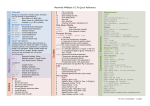
Contents
Functional Summary............................................................................................................... 3
Full Screen Editor ................................................................................................................... 5
Input/Output............................................................................................................................ 7
Audio and PWM Output.......................................................................................................... 8
Special Hardware Devices ..................................................................................................... 9
Graphics and Working with Colour ....................................................................................... 15
Game Playing Features........................................................................................................ 17
Defined Subroutines and Functions...................................................................................... 18
Implementation Details ......................................................................................................... 21
Predefined Read Only Variables .......................................................................................... 23
Commands ........................................................................................................................... 24
Functions.............................................................................................................................. 46
Obsolete Commands and Functions .................................................................................... 54
Appendix A Serial Communications ..................................................................................... 55
Appendix B I2C Communications.......................................................................................... 57
Appendix C 1-Wire Communications.................................................................................... 63
Appendix D SPI Communications......................................................................................... 64
Appendix E Loadable Fonts ................................................................................................. 66
Appendix F Special Keyboard Keys ..................................................................................... 67
Appendix G Tera Term Setup............................................................................................... 68
Appendix H Sprites............................................................................................................... 69
Appendix I Random File I/O ................................................................................................. 71
MMBasic Language Manual
Page 2
Functional Summary
Command and Program Input
At the prompt (the greater than symbol, ie, > ) you can enter a command line followed by the enter key and it
will be immediately run. This is useful for testing commands and their effects.
To enter a program you can use the EDIT command which will invoke the full screen editor built into
MMBasic. Line numbers are optional and if you use them you can enter a program at the command line by
preceding each program line with a line number.
When entering a line at the command prompt the line can be edited using the arrow keys to move along the
line, the Delete key to delete a character and the Insert key to switch between insert and overwrite. The up and
down arrow keys will move through a list of previously entered commands which can be edited and reused.
A program held in memory can be listed with LIST, run using the RUN command and cleared with the NEW
command. You can interrupt MMBasic at any time by typing CTRL-C and control will be returned to the
prompt.
Keyboard/Display
Input can come from either a keyboard or from a computer using a terminal emulator via the USB or serial
interfaces. Both the keyboard and the USB interface can be used simultaneously and can be detached or
attached at any time without affecting a running program.
Output will be simultaneously sent to the USB interface and the video display (VGA or composite) however
graphics commands operate on the video output only.
Line Numbers, Program Structure and Editing
The structure of a program line is:
[line-number] [label:]
command arguments [: command arguments] …
A label or line number can be used to mark a line of code. A label has the same specifications (length,
character set, etc) as a variable name but it cannot be the same as a command name. When used to
label a line the label must appear at the beginning of a line but after a line number (if used), and be
terminated with a colon character (:). Commands such as GOTO can use labels or line numbers to identify
the destination (in that case the label does not need to be followed by the colon character). For example:
GOTO xxxx
- - xxxx: PRINT "We have jumped to here"
Multiple commands separated by a colon can be entered on the one line (as in INPUT A : PRINT B).
Long programs (with or without line numbers) can be sent via USB to MMBasic using the XMODEM
command (Maximite only) or the AUTO command.
Program and Data Storage
In the DOS version of MMBasic the drive letters are as supported by Windows.
On the Maximite and Colour Maximite two “drives” are available for storing and loading programs and data:
Drive “A:” is a virtual drive using the PIC32’s internal flash memory and has a size of about 180KB on
the monochrome Maximite (a bit less with colour or CAN).
Drive “B:” is the SD card (if connected). It supports MMC, SD or SDHC memory cards formatted as
FAT16 or FAT32 with capacities up to 32Gb.
File names must be in 8.3 format prefixed with an optional drive prefix A: or B: (the same as DOS or
Windows). Long file names and directories are not supported. The default drive is B: and this can be changed
with the DRIVE command.
On the Maximite MMBasic will look for a file on startup called “AUTORUN.BAS” in the root directory of the
internal flash drive (A:) then the SD card (B:). If the file is found it will be automatically loaded and run,
otherwise MMBasic will print a prompt (“>”) and wait for input. If the Maximite has been restarted because
the watchdog timer has timed out and forced the Maximite to restart the file "RESTART.BAS" will be run
instead (see the WATCHDOG command for details).
Note that the video output will go blank for a short time while writing data to the internal flash drive A:. This
is normal and is caused by a requirement to shut off the video while reprogramming the memory. When using
MMBasic Language Manual
Page 3
drive A: you need to be careful not to wear out the flash (the same applies to SD cards). If drive A: is empty,
you could write and delete a file on it every day for 175 years before you would reach the endurance limit - but
if the interval was once a minute you would reach the limit in about 6 weeks.
Storage Commands and Functions
A program can be saved to either drive using the SAVE command. It can be reloaded using LOAD or merged
with the current program using MERGE. A saved program can also be loaded and run using the RUN
command. The RUN command can also be used within a running program, which enables one program to load
and transfer control to another. The CHAIN command allows a program to load and run another program
while retaining the current state of the program (ie, the value of variables, open files, loaded fonts,
open COM ports, etc). As long as a program can be broken down into modules CHAIN allows
programs of almost unlimited size to be run, even with limited memory.
The LIBRARY command will load a file containing user defined commands and functions which can
then be called by a running program. This provides an easy way to extend the language by creating
specialised libraries for maths functions, hardware drivers, etc. The LIBRARY command can also be
used to conserve memory by loading or unloading sections of a program as the program is run.
Data files can be opened using OPEN and read from using INPUT, LINE INPUT, or INPUT$() or written to
using PRINT or WRITE. On the SD card both data and programs are stored using standard text and can be
read and edited in Windows, Apple Mac, Linux, etc. An SD card can have up to 10 files open simultaneously
while the internal flash drive has a maximum of one file open at a time.
You can list the programs stored on a drive with the FILES command, delete them using KILL and rename
them using NAME. On an SD card the current working directory can be changed using CHDIR. A new
directory can be created with MKDIR or an old one deleted with RMDIR.
Whenever specified a file name can be a string constant (ie, enclosed in double quotes) or a string variable.
This means you must use double quotes if you are directly specifying a file name. Eg, KILL “TEST.BAS”.
However, quote marks are optional if the command is used at the command prompt. Note that symbols (such
as +, -, *) and valid keywords in an unquoted file name will cause an error. Quotes are always required if the
command is used within a program.
Timing
You can get the current date and time using the DATE$ and TIME$ functions and you can set them by
assigning the new date and time to them. The Colour Maximite with the optional battery backed clock will
never loose the time, on other Maximites the calendar will start from midnight 1st Jan 2000 on power up. On the
DOS version it will use the system time.
You can freeze program execution for a number of milliseconds using PAUSE. MMBasic also maintains an
internal stopwatch function (the TIMER function) which counts up in milliseconds. You can reset the timer to
zero or any other number by assigning a value to the TIMER.
Using SETTICK in the Maximite versions you can setup up to four “ticks” which will generate regular
interrupts with a period from one millisecond to over a month. See Interrupts below.
Expressions
In most cases where a number or string is required you can also use an expression. For example:
FNAME$ = “TEST”: RUN FNAME$ + ”.BAS”
Structured Statements
MMBasic supports a number of modern structured statements.
The DO WHILE … LOOP command and its variants make it easy to build loops without using the GOTO
statement. Defined subroutines and functions make it easy to add your own commands to MMBasic.
The IF… THEN command can span many lines with ELSEIF … THEN, ELSE and ENDIF statements as
required and also spaced over many lines. For example:
IF <condition> THEN
' start a multiline IF
<statements>
ELSEIF <condition> THEN
' the ELSEIF is optional
<statements>
ELSE
' the ELSE is optional
<statements>
ENDIF
' must be used to terminate the IF
MMBasic Language Manual
Page 4
Full Screen Editor
An important productivity feature of MMBasic is the full screen editor (this is not available in the DOS version
of MMBasic). It will work using an attached video screen (VGA or composite) and over USB with a VT100
compatible terminal emulator (Tera Term is recommended).
The full screen editor is invoked with the EDIT command. If you just type EDIT without anything else the
editor will automatically start editing whatever is in program memory. If program memory is empty you will
be presented with an empty screen.
The cursor will be automatically positioned at the last place that you were editing at and, if your program had
just been stopped by an error, the cursor will be positioned at the line that caused the error.
You can also run the editor with a file name (eg, EDIT "file.ext") and the editor will edit that file while leaving
program memory untouched. This is handy for examining or changing files on the disk without disturbing your
program.
If you are used to an editor like Notepad you will find that the operation of the full screen editor is familiar.
The arrow keys will move your cursor around in the text, home and end will take you to the beginning or end of
the line. Page up and page down will do what their titles suggest. The delete key will delete the character at
the cursor and backspace will delete the character before the cursor. The insert key will toggle between insert
and overtype modes.
About the only unusual key combination is that two home key presses will take you to the start of the program
and two end key presses will take you to the end.
At the bottom of the screen the status line will list the various function keys used by the editor and their action.
In more details these are:
ESC
MMBasic Language Manual
This will cause the editor to abandon all changes and return to the command prompt with
the program memory unchanged. If you have changed the text you will be asked if this
is really what you want to do.
Page 5
F1: SAVE
This will save the program to program memory and return to the command prompt. If
you are editing a disk file it will save that file to the disk.
F2: RUN
This will save the program to program memory and immediately run it.
F3: FIND
This will prompt for the text that you want to search for. When you press enter the
cursor will be placed at the start of the first entry found.
SHIFT-F3
Once you have used the search function you can repeatedly search for the same text by
pressing SHIFT-F3.
F4: MARK
This is described in detail below.
F5: PASTE
This will insert (at the current cursor position) the text that had been previously cut or
copied (see below).
CTRL-F
This will insert (at the current cursor position) a file residing on the disk. Note that while
this key is not listed on the status line it is always available.
You can also use control keys instead of the functions keys listed above. These control keystrokes are:
LEFT
HOME
DEL
F3
Ctrl-S
Ctrl-U
Ctrl-]
Ctrl-R
RIGHT
END
INSERT
ShiftF3
Ctrl-D
Ctrl-K
Ctrl-N
Ctrl-G
UP
PageUp
F1
F4
Ctrl-E
Ctrl-P
Ctrl-Q
Ctrl-T
DOWN
PageDn
F2
F5
Ctrl-X
Ctrl-L
Ctrl-W
Ctrl-Y
If you pressed the mark key (F4) the editor will change to the mark mode. In this mode you can use the arrow
keys to mark a section of text which will be highlighted in reverse video. You can then delete, cut or copy the
marked text. In this mode the status line will change to show the functions of the function keys in the mark
mode. These keys are:
ESC
Will exit mark mode without changing anything.
F4: CUT
Will copy the marked text to the clipboard and remove it from the program.
F5: COPY
Will just copy the marked text to the clipboard.
DELETE
Will delete the marked text leaving the clipboard unchanged.
The best way to learn the full screen editor is to simply fire it up and experiment.
The editor is a very productive method of writing a program. Using the OPTION Fnn command you can
program a function key to generate the command "EDIT" when pressed. So, with one key press you can jump
into the editor where you can make a change. Then by pressing the F2 key you can save and run the program.
If your program stops with an error you can press the edit function key and be back in the editor with the cursor
positioned at the line that caused the error. This edit/run/edit cycle is very fast.
If you are using the full screen editor over USB with Terra Term you must set Terra Term to a screen size of 80
characters by 36 lines. See Appendix G for details.
Note that a terminal emulator like Tera Term can loose its position in the text with multiple fast keystrokes
(like the up and down arrows). If this happens you can press the HOME key twice which will force the editor
to jump to the start of the program and redraw the display.
MMBasic Language Manual
Page 6
Input/Output
The following functions are only supported on the Maximite variants (not on the DOS version).
External Input/Output
You can configure an external I/O pin using the SETPIN command, set its output using the PIN()= command
and read the current input value using the PIN() function. Digital I/O uses the number zero to represent a low
voltage and any non-zero number for a high voltage. An analogue input will report the measured voltage as a
floating point number.
The original Maximite has 20 I/O pins numbered 1 to 20. Pins 1 to 10 can be used for analog input and digital
input/output with a maximum input voltage of 3.3V. Pins 11 to 20 are digital only but support input voltages
up to 5V and can be set to open collector.
The DuinoMite has completely different and confusing allocations. See "DuinoMite MMBasic ReadMe.pdf"
Normally digital output is 0V (low) to 3.3V (high) but you can use open collector to drive 5V circuit. This
means that the pin can be pulled down (when the output is low) but will go high impedance when the output is
high. So, with a pull up resistor to 5V an output configured as open collector you can drive 5V logic signals.
Typical value of the pull up resistor is 1K to 4.7K.
Arduino Connector
In addition to the 20 I/O pins described above the Colour Maximite has an extra 20 I/O pins on the Arduino
compatible connector (40 I/O pins in total). These are labelled D0 to D13 and A0 to A5.
You can use the labels D0, D1, etc in the SETPIN and PIN statements or you can use their corresponding
numbers (D0 = 21, D1 = 22, etc and A0 = 35, A1 = 36, etc). The digital pins (D0 to D13) have the same
characteristics (5V, open collector, etc) as the digital pins 11 to 20 and the analog capable pins (A0 to A5) have
the same capabilities as pins 1 to 10.
Communications
Two serial ports are supported with speeds up to 19200 baud with configurable buffer sizes and optional
hardware flow control. The serial ports are opened using the OPEN command and any command or function
that uses a file number can be used to send and receive data. See Appendix A for a full description.
Communications to slave or master devices on an I2C bus is supported with eight commands (see Appendix B
for a full description). MMBasic fully supports bus master and slave mode, 10 bit addressing, address masking
and general call, as well as bus arbitration (ie, bus collisions in a multi-master environment).
The Serial Peripheral Interface (SPI) communications protocol is supported with the SPI command. See
Appendix D for the details. The Dallas 1-Wire protocol is also supported. See Appendix C for details.
Interrupts
Most external I/O pins can be configured to generate an interrupt using the SETPIN command with many
interrupts (including the tick interrupt) active at any one time. Interrupts can be set up to occur on a rising or
falling digital input signal and will cause an immediate branch to a specified line number, label or a user
defined subroutine. The target can be the same or different for each interrupt. Return from an interrupt is via
the IRETURN statement except where a user defined subroutine is used (in that case END SUB or EXIT SUB
is used). Within the interrupt routine GOTO, GOSUB and calls to other subroutines can be used.
If two or more interrupts occur at the same time they will be processed in order of pin numbers (ie, an interrupt
on pin 1 will have the highest priority). During processing of an interrupt all other interrupts are disabled until
the interrupt routine returns with an IRETURN. During an interrupt (and at all times) the value of the interrupt
pin can be accessed using the PIN() function.
Up to four periodic interrupts (or regular “ticks”) with periods specified in milliseconds can be setup using the
SETTICK statement. This interrupt has the lowest priority. Using the ON KEY command an interrupt can be
generated whenever a key is pressed.
Interrupts can occur at any time but they are disabled during INPUT statements. If you need to get input from
the keyboard while still accepting interrupts you should use the INKEY$ function or the ON KEY command.
When using interrupts the main program is completely unaffected by the interrupt activity unless a variable
used by the main program is changed during the interrupt.
For most programs MMBasic will respond to an interrupt in under 100µS. To prevent slowing the main
program by too much an interrupt should be short and exit as soon as possible. Also remember to disable an
interrupt when you have finished needing it – background interrupts can cause strange and non-intuitive bugs.
MMBasic Language Manual
Page 7
Audio and PWM Output
On the Maximite variants there are a number of ways that you can use the sound output. You can play
synthesised music, generate tones or generate program controlled voltages (PWM).
PLAYMOD
This command will play synthesised music in the background while the program is running. The music must
be in the MOD format and the file containing the music must be located on the internal flash drive (drive A:).
The audio is high quality and MMBasic will generate full stereo on the Colour Maximite.
The MOD format is a music file format originating from the MOD file format on Amiga systems in the late
1980s. It is not a recording of the music (like a MP3 file) - instead it contains instructions for synthesising the
music. On the original Amiga this task was performed by dedicated hardware.
MMBasic will read this file and continuously play the music in the background while the program that
launched the music will continue running in the foreground. Be aware that synthesising music is a CPU
intensive activity and uses a lot of memory and this could affect the performance of the program.
A description of the MOD format can be found at: http://en.wikipedia.org/wiki/MOD_(file_format)
A large selection of files that can be played on the Maximite can be found at: http://modarchive.org (look for
files with the .MOD extension). Because the file must be located on drive A: to play it would be wise to select
reasonably small files.
You can also create your own music using a tracker. For an example see: http://www.modplug.com
TONE
This command will create two tones for the Colour Maximite that will be outputted separately on the left and
right sound channels. On the monochrome Maximite only one tone is generated. The tone is a synthesised sine
wave and can be in the range of 1Hz to 20KHz with a resolution of 1Hz and is very accurate as it is locked to
the PIC32's crystal oscillator. When the frequency is changed there is no interruption in the output so the
output can be made to glide smoothly across a range of frequencies.
The playing time can be specified in milliseconds and the tone will play in the background (ie, the program
continues running).
SOUND
The sound command is included only for compatibility with older programs. It generates a single frequency
square wave and should be replaced with the tone or PWM command in new programs.
PWM
The PWM (Pulse Width Modulation) command allows the Maximite to generate square waves with a program
controlled duty cycle. By varying the duty cycle you can generate a program controlled voltage output for use
in controlling external devices that require an analog input (power supplies, motor controllers, etc). The Colour
Maximite has two PWM outputs while the monochrome Maximite has one.
The frequency for both PWM outputs is the same and can be from 20Hz to 1MHz. The duty cycle for each
output can be independently set from between 0% and 100% with a 0.1% resolution when the frequency is
below 50KHz (above 50KHz the resolution is 1% or better up to 500KHz).
When the Maximite is powered up or the PWM OFF command is used the PWM outputs will be set to high
impedance (they are neither off nor on). So, if you want the PWM output to be low by default (zero power in
most applications) you should use a resistor to pull the output to ground when it is set to high impedance.
Similarly, if you want the default to be high (full power) you should connect the resistor to 3.3V.
This command uses the sound output for generating the PWM signal so the components on this output may
need to be changed or removed to allow this output to work as a PWM output.
MMBasic Language Manual
Page 8
Special Hardware Devices
To make it easier for a program to interact with the external world MMBasic includes support for a number of
common peripheral devices.
These are:
Infrared remote control receiver and transmitter
Ultrasonic distance sensor
LCD display modules
The DS18B20 temperature sensor
Numeric keypads
Battery backed clock
Rotary Encoder
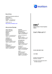
Infrared Remote Control Decoder
You can easily add a remote control to your project using the IR command. When enabled this function will
run in the background and interrupt the running program whenever a key is pressed on the IR remote control. It
will work with any Sony compatible remote control including ones that generate 12, 15 or 20 bit messages.
Most cheap programmable remote controls will generate these commands and using one of these you can add a
sophisticated flair to your project.
Pin 12 - Colour Maximite
To detect the IR signal you need an IR receiver connected to
Pin 14 - mono Maximite
pin 12 on the Colour Maximite and TFT-Maximite, pin 14 on
Pin 7 - DuinoMite
the monochrome Maximite and pin 7 on the DuinoMite. This
is illustrated in the diagram on the right. The IR receiver will
IR Receiver
sense the IR light, demodulate the signal and present it as a
TTL voltage level signal to this pin. Setup of the I/O pin is
+5V
automatically done by the IR command.
Maximite
Sony remotes use a 40KHz modulation frequency but receivers
for that frequency can be hard to find. Generally 38KHz
receivers will work fine but maximum sensitivity will be
achieved with a 40KHz device such as the Vishay TSOP4840.
Examples of 38KHz receivers that work include the Vishay
TSOP4838, Jaycar ZD1952 and Altronics Z1611A.
To setup the decoder you use the command:
IR dev, key, interrupt
Where dev is a variable that will be updated with the device code and key is the variable to be updated with the
key code. Interrupt is the interrupt label to call when a new key press has been detected. The IR decoding is
done in the background and the program will continue after this command without interruption.
This is an example of using the IR decoder:
IR DevCode, KeyCode, IR_Int
' start the IR decoder
DO
< body of the program >
LOOP
IR_Int:
' a key press has been detected
PRINT "Received device = " DevCode " key = " KeyCode
IRETURN
Sony remote controls can address many different devices (VCR, TV, etc) so the program would normally
examine the device code first to determine if the signal was intended for the program and, if it was, then take
action based on the key pressed. There are many different devices and key codes so the best method of
determining what codes your remote generates is to use the above program to discover the codes.
MMBasic Language Manual
Page 9
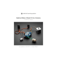
Infrared Remote Control Transmitter
Using the IR SEND command you can transmit a 12 bit
Sony infrared remote control signal. This is intended for
+5V
Maximite or Micromite† communications but it will also
work with Sony equipment that uses 12 bit codes. Note that
all Sony products require that the message be sent three
58 ohms
times with a 26mS delay between each message.
The circuit on the right illustrates what is required. The
transistor is used to drive the infrared LED because the
IR
output of the Maximite is limited to about 14mA. This
LED
circuit provides about 50mA to the LED.
Maximite
To send a signal you use the command:
BC338
IR SEND pin, dev, cmd
1K
Where pin is the I/O pin used, dev is the device code to send
and key is the key code. Any I/O pin on the Maximite can
be used and you do not have to set it up beforehand (the
IR SEND command will automatically do that).
Note that the modulation frequency used is 38KHz and this matches the common IR receivers (described in the
previous page) for maximum sensitivity when communicating with another Maximite or Micromite.
Measuring Temperature
The DS18B20() function will get the temperature from a DS18B20 temperature sensor. This device can be
purchased on eBay for about $5 in a variety of packages including a waterproof probe version.
The DS18B20 can be powered separately by a 3V to 5V supply
or it can operate on parasitic power from the Maximite as shown
on the right. Multiple sensors can be used but a separate I/O pin
3V to
and pullup resistor is required for each one.
5V
To get the current temperature you just use the DS18B20()
4.7K
function in an expression.
For example:
Any
PRINT "Temperature: " DS18B20(pin)
I/O Pin
Where 'pin' is the I/O pin to which the sensor is connected. You
do not have to configure the I/O pin, that is handled by
MMBasic.
The returned value is in degrees C with a resolution of 0.25ºC
and is accurate to ±0.5 ºC.
The time required for the overall measurement is 200mS and the running program will halt for this period while
the measurement is being made. This also means that interrupts will be disabled for this period. If you do not
want this you can separately trigger the conversion using the DS18B20 START command then later use the
DS18B20() function to retrieve the temperature reading. The DS18B20() function will always wait if the
sensor is still making the measurement.
For example:
DS18B20 START 15
< do other tasks >
PRINT "Temperature: " DS18B20(15)
LCD Display
The LCD command will display text on a standard LCD module with the
minimum of programming effort.
This command will work with LCD modules that use the KS0066, HD44780 or
SPLC780 controller chip and have 1, 2 or 4 lines. Typical displays include the
LCD16X2 (futurlec.com), the Z7001 (altronics.com.au) and the QP5512
†
For details of the Micromite go to http://geoffg.net/micromite.html
MMBasic Language Manual
Page 10
(jaycar.com.au). eBay is another good source where prices can range from $10 to $50.
To setup the display you use the LCD INIT command:
LCD INIT d4, d5, d6, d7, rs, en
D4, d5, d6 and d7 are the I/O pins that connect to inputs D4, D5, D6 and D7 on the LCD module (inputs D0 to
D3 and R/W on the module should be connected to ground). 'rs' is the pin connected to the register select input
on the module (sometimes called CMD or DAT). 'en' is the pin connected to the enable or chip select input on
the module.
Any I/O pins can be used and you do not have to set them up beforehand (the LCD command automatically
does that for you). The following diagram shows a typical set up.
To display characters on the module you use the LCD command:
LCD line, pos, data$
Where line is the line on the display (1 to 4) and pos is the position on the line where the data is to be written
(the first position on the line is 1). data$ is a string containing the data to write to the LCD display. The
characters in data$ will overwrite whatever was on that part of the LCD.
The following shows a typical usage.
LCD INIT 2, 3, 4, 5, 23, 24
LCD 1, 2, "Temperature"
LCD 2, 6, STR$(DS18B20(15))
' DS18B20 connected to pin 15
Note that this example also uses the DS18B20 function to get the temperature (described above).
Keypad Interface
A keypad is a simple method of entering data into an MMBasic based system. MMBasic supports either a 4x3
keypad or a 4x4 keypad and the monitoring and decoding of key presses is done in the background. When a
key press is detected an interrupt will be issued where the program can deal with it.
Examples of a 4x3 keypad and a 4x4 keypad are the Altronics S5381 and S5383 (go to www.altronics.com).
To enable the keypad feature you use the command:
KEYPAD
var, int, r1, r2, r3, r4, c1, c2, c3, c4
Where var is a variable that will be updated with the key code and int is the label of the interrupt to call when a
new key press has been detected. r1, r2, r3 and r4 are the pin numbers used for the four row connections to the
MMBasic Language Manual
Page 11
keypad. Note that these must be pulled up to 3.3V by individual 10K resistors (see the diagram below). c1, c2,
c3 and c4 are the column connections. c4 is only used with 4x4 keypads and should be omitted if you are using
a 4x3 keypad.
Any I/O pins can be used and you do not have to set them up beforehand, the KEYPAD command will
automatically do that for you.
The detection and decoding of key presses is done in the background and the program will continue after this
command without interruption. When a key press is detected the value of the variable var will be set to the
number representing the key (this is the number inside the circles in the diagram above). Then the interrupt
will be called.
For example:
Keypad KeyCode, KP_Int, 2, 3, 4, 5, 21, 22, 23
' 4x3 keyboard
DO
< body of the program >
LOOP
KP_Int:
PRINT "Key press = " KeyCode
IRETURN
' a key press has been detected
Measuring Distance
Using a HC-SR04 ultrasonic sensor and the DISTANCE() function you can measure the distance to a target.
This device can be found on eBay for about $4 and it will measure the
distance to a target from 3cm to 3m. It works by sending an ultrasonic
sound pulse and measuring the time it takes for the echo to be returned.
In MMBasic you use the DISTANCE function:
d = DISTANCE(trig, echo)
Where trig is the I/O pin connected to the "trig" input of the sensor and
echo is the pin connected "echo" output of the sensor. You can also use
3-pin devices and in that case only one pin number is specified.
The value returned is the distance in centimetres to the target or -1 if no
target was detected. If you repeatedly call this function you must arrange for a delay of at least 60mS between
each call otherwise errors may occur (caused by an echo from the previous sound pulse).
MMBasic Language Manual
Page 12
The I/O pins are automatically configured by this function but note that they should be 5V capable as the
HC-SR04 is a 5V device. You can use multiple sensors connected to different I/O pins or even sharing the one
trigger pin if care is taken to prevent one sensor from interfering with another.
Rotary Encoders
A rotary encoder is a handy method of adjusting the value of parameters in a
microcontroller project. A typical encoder can be mounted on a panel with a knob
and looks like a potentiometer. As the knob is turned it generates a series of signals
known as a Gray Code. The program fragment below shows how to decode this
code to update a variable in MMBasic.
A standard encoder has two outputs (labelled RA and RB) and a common ground.
The outputs should be wired with pullup resistors as shown below:
And this program fragment can be used to decode the output:
SETPIN 3, DIN
SETPIN 2, INTH, RInt
' setup RB as an input
' setup an interrupt when RA goes high
DO
< main body of the program >
LOOP
RInt:
IF PIN(3) = 1 then
Value = Value + 1
ELSE
Value = Value - 1
ENDIF
IRETURN
' Interrupt to decode the encoder output
' clockwise rotation
' anti clockwise rotation
This program assumes that the encoder is connected to I/O pins 2 and 3 however any pins can be used by
changing the pin numbers in the program. "Value" is the variable whose value will be updated as the shaft of
the encoder is rotated.
Note that this program is intended for simple user input where a skipped or duplicated step is not considered
important. It is not suitable for high speed or precision input.
Program courtesy TZAdvantage on the Back Shed Forum.
MMBasic Language Manual
Page 13
Real Time Clock Interface
The original monochrome Maximite and the DuinoMite do not have a built in real time clock, which means that
the time is lost when the power is removed. Using the RTC GETTIME command and a PCF8563 real time
clock integrated circuit you can automatically reset the Maximite's clock on start up.
The PCF8563 is popular and cheap and will keep accurate time to about ±50 ppm even with the power removed
(it is battery backed). It can be purchased for as cheap as $3 on eBay and complete modules using the
PCF8563 along with a battery can be found for as little as $8.
The PCF8563 is an I2C device and should be connected to the I2C I/O pins of the Maximite. Also, because the
PCF8563 draws very little current (even when communicating via I2C) it can be permanently connected to the
battery (typical battery life is 15 years).
This circuit shows a typical application (the pin numbers are for the monochrome Maximite).
The 32pF adjustable capacitor should be used to trim the crystal frequency for very accurate timekeeping but
that can be tedious as it will involve checking the time for drift over days and weeks. If you don't want to do
that you can substitute a 10pF capacitor or leave it out completely and the timekeeping will still be reasonably
accurate.
Before you can use the PCF8563 its time must be first set. That is done with the RTC SETTIME command
which uses the format RTC SETTIME year, month, day, hour, minute, second. Note that the year is just the
last two digits (ie, 14 for 2014) and hour is in 24 hour format. For example, the following will set the PCF8563
to 4PM on the 10th November 2014:
RTC SETTIME 14, 11, 10, 16, 0, 0
To get the time you use the RTC GETTIME command which will read the time from the PCF8563 and set the
clock inside the Maximite. Normally this command will be placed at the beginning of the program so that the
time is set on power up.
MMBasic Language Manual
Page 14
Graphics and Working with Colour
Graphics
Graphics commands operate on the video output only (not USB). Coordinates are measured in pixels with x
being the horizontal coordinate and y the vertical coordinate. The top left of the screen is at location x = 0 and
y = 0 with increasing positive numbers representing movement down the screen and to the right. The number
of pixels on the screen is defined by the read-only variables MM.HRES and MM.VRES which change
depending on the video mode selected (VGA or composite PAL/NTSC).
You can clear the screen with CLS and an individual pixel can be turned on or off and its colour set with
PIXEL(x,y) = . You can draw lines and boxes with LINE, and circles using CIRCLE. You can also set the
screen location (in pixels) of the PRINT output using @(x,y) and the SAVEBMP command will save the
current screen as a BMP file. LOADBMP will load and display a bitmap image stored on the SD card.
Working with Colour
The Colour Maximite supports eight colours (black, blue, green, cyan, red, purple, yellow and white). The
monochrome Maximite or DuinoMite support just two (black and white). In most places you can also specify
the colour as -1 to invert a pixel (this is useful in animation).
Throughout MMBasic you can refer to the colours by their name or their corresponding numbers where
black = 0, blue = 1, green = 2, etc through to white = 7. Commands such as LINE and CIRCLE use this colour
or number to specify the colour to draw. For example:
CIRCLE (100, 100), 50, CYAN
will draw a circle in cyan.
CIRCLE (100, 100), 50, 3
will also draw a circle in cyan (colour = 3).
You can also specify a default colour that will be used for all screen output with the COLOUR command. For
example: COLOUR PURPLE will set the colour of text to purple (and any other output where the colour is
not specified). The COLOUR command also takes a second parameter for the background colour. So,
COLOUR YELLOW, BLUE specifies that text will be displayed in yellow on a blue background.
In addition to the COLOUR command you can change the colour of text by embedding colour codes into
strings using the CLR$() function. For example, the following will display each word in a different colour:
Txt$ = "This is " + CLR$(RED) "red " + CLR$(YELLOW) + "yellow"
PRINT Txt$
You can also use this function to set the background colour by supplying a second parameter. For example:
PRINT CLR$(YELLOW,RED) " ALARM "
If the function is used without any parameters (eg, CLR$()) it will reset the colours to the defaults set by the
last COLOUR command. The colours are also reset when the print command terminates.
This function simply generates a two character string where the first character is the number 128 plus the
foreground colour number and the second character is the number 192 plus the background colour number.
You can use this trick to embed colour commands in any text, even text read from a text file on the SD card.
Colour Modes
The video system can be configured into one of four modes using the MODE command. This enables the
programmer to trade off the number of colours used on the screen and the graphic resolution against the amount
of memory required by the video driver. Modes 1 and 4 use the least amount of memory while mode 3 uses the
most. The syntax of the MODE command is: MODE colour-mode, palette
The 'colour-mode' can be one of four numbers:
1 Monochrome mode. In this mode the Colour MMBasic operates the same as the monochrome MMBasic
for the Maximite and has the maximum amount of free memory available for programs and data. The
second argument of the MODE command ('palette') selects the colour to be used for all output. It can be
any colour number from black to white.
2 Four colour mode. In this mode four colours (including black) are available. The actual colours are
selected by a number (1 to 6) used in the second argument of the MODE command ('palette'). See the
following image or the MODE command for a listing of the actual colours available.
3 Eight colour mode. In this mode all eight colours are available and can be used simultaneously anywhere
on the screen. The 'palette' argument is not required and will be ignored if specified. MODE 3 uses the
most memory but there still is plenty left for programs and data. This is the default when the Colour
Maximite is first powered up.
MMBasic Language Manual
Page 15
4
240x216 pixel mode. In this mode all eight colours are available and the video resolution is halved
(meaning that characters and graphics are doubled in size). This mode is most suitable for games as all
colours are available, it has the maximum amount of free memory and drawing of graphics is very fast.
The 'palette' argument is not required and will be ignored if specified.
This is an illustration of what the colour modes look like (Mode 3 was used to generate this image):
You can change the mode and the palette at any time and as often as you need, even within a running program.
Scan Line Colour Override
In mode 1 (monochrome) there is an additional facility to change the colour of each horizontal line of pixels on
the screen using the SCANLINE command. This is intended mostly for programmers writing games and
provides limited control over colour while still providing the maximum amount of free memory. The syntax is:
SCANLINE colour, startline, endline
This command can only be used in MODE 1, 7 (monochrome with the colour set to white) and is used to set the
colour for each horizontal scan line of pixels on the screen. 'colour' is the colour to be used and can be any one
of the eight colours, 'startline' is the starting scan line to be set to that colour and 'endline' is the ending line.
The scan lines are numbered from 0 at the top of the screen to 431 at the bottom of the screen. The numbering
is the same as that used when specifying the vertical coordinates of a pixel.
You can use multiple SCANLINE commands to set multiple scan lines to different colours. For example:
SCANLINE RED, 0, 9
' set the top 10 lines to red
SCANLINE YELLOW, 120
' and set only line 120 to yellow
SCANLINE BLUE, 200, 219
' and set a band of 20 lines to blue
To turn off the override imposed by the use of SCANLINE commands you can use the MODE command to
reselect mode 1 or a change to a different mode. It is also automatically turned off when control is returned to
the command prompt.
MMBasic Language Manual
Page 16
Game Playing Features
MMBasic 4.x introduces a number of features that are intended to make it easier to write games on the
Maximite.
MODE 4
The colour MODE 4 described in the previous section is mostly intended for games. It provides eight colours
and leaves plenty of free memory for the other aspects of an animated game (sprites, arrays, and so on).
Because this colour mode has only one quarter of the pixels the graphics operations are much faster due to the
fact that there are fewer pixels that need to be manipulated by MMBasic when drawing on the screen.
BLIT
This command will move an area of the video screen from one location to another. The destination can overlap
the source area and the BLIT command will copy the video data correctly to avoid corruption. On the Colour
Maximite you can also independently specify what colour planes to copy.
This method of moving video data is much faster than copying pixels one by one and allows for rapid
animation on the screen. It can also be used to replicate a pattern like a border or a brick wall to build a
complete image.
SPRITES
A sprite is a 16x16 bit graphic image that can be moved about on the screen independently of the background.
When the sprite is displayed MMBasic will automatically save the background text and graphics under the
sprite and when the sprite is turned off or moved MMBasic will restore the background.
The sprites are defined in a file which is loaded into memory using the SPRITE LOAD command, the number
of sprites contained in the file is only limited by the amount of available memory. Each sprite in the file can
contain pixels of any colour (on the Colour Maximite) and can also have transparent pixels which allow the
background to show through.
A special function exists to report if the sprite has collided with the edge of the screen or other sprites.
See Appendix H for a detailed description of creating and manipulating sprites.
LOADBMP
The LOADBMP command will load a colour or monochrome bitmap image and display it at a specified
location on the screen. This is handy for loading background images for games.
FONTS
The FONT command is normally used to load custom alphanumeric character fonts but a font's character can
be as large as 64 pixels high and 255 pixels wide.
This means that a specially designed font can be used to load custom designed graphic images and display them
anywhere on the screen at high speed.
PEEK/POKE
With the PEEK and POKE commands you can now use constant keywords to access special sections of
memory (like the video memory) and these keywords will be valid with future versions of MMBasic. This
makes it easy to access internal MMBasic data structures in a portable manner.
KEYDOWN FUNCTION
They KEYDOWN function makes it easy to tell if the user is holding down a key on the PS2 keyboard (like an
arrow key). While the key is held down KEYDOWN will return the numeric value of the key, when no key is
held down the function will return zero.
The KEYDOWN function will also remove any characters in the keyboard input buffer but, when playing a
game, the user often still has their finger on a key when the game ends. For that reason the program should
include the following line which will wait for the user to release the key and clear the buffer:
DO WHILE KEYDOWN AND INKEY$ <> "" : LOOP
MMBasic Language Manual
Page 17
Defined Subroutines and Functions
Defined subroutines and functions are useful features to help in organising programs so that they are easy to
modify and read. A defined subroutine or function is simply a block of programming code that is contained
within a module and can be called from anywhere within your program. It is the same as if you have added
your own command or function to the language.
For example, assume that you would like to have the command FLASH added to MMBasic, its job would be to
flash the power light on the Maximite. You could define a subroutine like this:
Sub FLASH
Pin(0) = 1
Pause 100
Pin(0) = 0
End Sub
Then, in your program you just use the command FLASH to flash the power LED. For example:
IF A <= B THEN FLASH
If the FLASH subroutine was in program memory you could even try it out at the command prompt, just like
any command in MMBasic. The definition of the FLASH subroutine can be anywhere in the program but
typically it is at the start or end. If MMBasic runs into the definition while running your program it will simply
skip over it.
Subroutine Arguments
Defined subroutines can have arguments (sometimes called parameter lists). In the definition of the subroutine
they look like this:
Sub MYSUB (arg1, arg2$, arg3)
<statements>
<statements>
End Sub
And when you call the subroutine you can assign values to the arguments. For example:
MYSUB 23, "Cat", 55
Inside the subroutine arg1 will have the value 23, arg2$ the value of "Cat", and so on. The arguments act
like ordinary variables but they exist only within the subroutine and will vanish when the subroutine ends. You
can have variables with the same name in the main program and they will be different from arguments defined
for the subroutine (at the risk of making debugging harder).
When calling a subroutine you can supply less than the required number of values. For example:
MYSUB 23
In that case the missing values will be assumed to be either zero or an empty string. For example, in the above
case arg2$ will be set to "" and arg3 will be set to zero. This allows you to have optional values and, if the
value is not supplied by the caller, you can take some special action.
You can also leave out a value in the middle of the list and the same will happen. For example:
MYSUB 23, , 55
Will result in arg2$ being set to "".
Local Variables
Inside a subroutine you will need to use variables for various tasks. In portable code you do not want the name
you chose for such a variable to clash with a variable of the same name in the main program. To this end you
can define a variable as LOCAL.
For example, this is our FLASH subroutine but this time we have extended it to take an argument (nbr) that
specifies how many times to flash the LED.
Sub FLASH ( nbr )
Local count
For count = 1 To nbr
Pin(0) = 1
Pause 100
Pin(0) = 0
MMBasic Language Manual
Page 18
Pause 150
Next count
End Sub
The counting variable (count) is declared as local which means that (like the argument list) it only exists
within the subroutine and will vanish when the subroutine exits. You can have a variable called count in your
main program and it will be different from the variable count in your subroutine.
If you do not declare the variable as local it will be created within your program and be visible in your main
program and subroutines, just like a normal variable.
You can define multiple items with the one LOCAL command. If an item is an array the LOCAL command
will also dimension the array (ie, you do not need the DIM command). For example:
LOCAL NBR, STR$, ARR(10, 10)
You can also use local variables in the target for GOSUBs. For example:
GOSUB MySub
...
MySub:
LOCAL X, Y
FOR X = 1 TO ...
FOR Y = 5 TO ...
<statements>
RETURN
The variables X and Y will only be valid until the RETURN statement is reached and will be different from
variables with the same name in the main body of the program.
Defined Functions
Defined functions are similar to defined subroutines with the main difference being that the function is used to
return a value in an expression. For example, if you wanted a function to select the maximum of two values
you could define:
Function Max(a, b)
If a > b
Max = a
Else
Max = b
EndIf
End Function
Then you could use it in an expression:
SetPin 1, 1 : SetPin 2, 1
Print "The highest voltage is" Max(Pin(1), Pin(2))
The rules for the argument list in a function are similar to subroutines. The only difference is that brackets are
required around the argument list when you are calling a function (they are optional when calling a subroutine).
To return a value from the function you assign a value to the function's name within the function. If the
function's name is terminated with a $ the function will return a string, otherwise it will return a number.
Within the function the function's name acts like a standard variable.
As another example, let us say that you need a function to format time in the AM/PM format:
Function MyTime$(hours, minutes)
Local h
h = hours
If hours > 12 Then h = h - 12
MyTime$ = Str$(h) + ":" + Str$(minutes)
If hours <= 12 Then
MyTime$ = MyTime$ + "AM"
Else
MyTime$ = MyTime$ + "PM"
EndIf
End Function
MMBasic Language Manual
Page 19
As you can see, the function name is used as an ordinary local variable inside the subroutine. It is only when
the function returns that the value assigned to MyTime$ is made available to the expression that called it.
This example also illustrates that you can use local variables within functions just like subroutines.
Passing Arguments by Reference
If you use an ordinary variable (ie, not an expression) as the value when calling a subroutine or a function, the
argument within the subroutine/function will point back to the variable used in the call and any changes to the
argument in your routine will also be made to the supplied variable. This is called passing arguments by
reference.
For example, you might define a subroutine to swap two values, as follows:
Sub Swap a, b
Local t
t = a
a = b
b = t
End Sub
In your calling program you would use variables for both arguments:
Swap nbr1, nbr2
And the result will be that the values of nbr1 and nbr2 will be swapped.
Unless you need to return a value via the argument you should not use an argument as a general purpose
variable inside a subroutine or function. This is because another user of your routine may unwittingly use a
variable in their call and that variable will be "magically" changed by your routine. It is much safer to assign
the argument to a local variable and manipulate that instead.
Additional Notes
There can be only one END SUB or END FUNCTION for each definition of a subroutine or function. To exit
early from a subroutine (ie, before the END SUB command has been reached) you can use the EXIT SUB
command. This has the same effect as if the program reached the END SUB statement. Similarly you can use
EXIT FUNCTION to exit early from a function.
You cannot use arrays in a subroutine or function's argument list however the caller can use them. For
example, this is a valid way of calling the Swap subroutine (discussed above):
Swap dat(i), dat(i + 1)
This type of construct is often used in sorting arrays.
Loadable Libraries
The use of defined subroutines and functions should reduce the need to add specialised features to MMBasic.
For instance, there have been a few requests to add bit shifting functions to the language. Now you can do that
yourself… this is the right shift function:
Function RShift(nbr, bits)
If nbr < 0 or bits < 0 THEN ERROR "Invalid argument"
RShift = nbr\(2^bits)
End Function
You can now use this function as if it is a part of the language:
a = &b11101001
b = RShift(a, 3)
After running this fragment of code the variable b would have the binary value of 11101.
The defined subroutine and function is intended to be a portable lump of code that you can insert into any
program. This is why MMBasic has the LIBRARY command which allows you to load files containing user
defined subroutines and functions into memory. These functions/subroutines are then available to the running
program and are indistinguishable from the built-in commands and functions.
So, it would be easy to create a library of bit manipulation functions like that described above and load them
within any program that might need them. The same for specialised maths functions, drivers for special
hardware and so on.
MMBasic Language Manual
Page 20
Implementation Details
Naming Conventions
Command names, function names, labels, variable names, file names, etc are not case sensitive, so that "Run"
and "RUN" are equivalent and "dOO" and "Doo" refer to the same variable.
There are two types of variable: numeric which stores a floating point number (eg, 45.386), and string which
stores a string of characters (eg, “Tom”). String variable names are terminated with a $ symbol (eg, name$)
while numeric variables are not.
Variable names and labels can start with an alphabetic character or underscore and can contain any alphabetic
or numeric character, the period (.) and the underscore (_). They may be up to 32 characters long. A variable
name or a label must not be the same as a function or one of the following keywords: THEN, ELSE, GOTO,
GOSUB, TO, STEP, FOR, WHILE, UNTIL, LOAD, MOD, NOT, AND, OR, XOR, AS. Eg, step = 5 is
illegal as STEP is a keyword. In addition, a label cannot be the same as a command name.
Constants
Numeric constants may begin with a numeric digit (0-9) for a decimal constant, &H for a hexadecimal
constant, &O for an octal constant or &B for a binary constant. For example &B1000 is the same as the
decimal constant 8.
Decimal constants may be preceded with a minus (-) or plus (+) and may terminated with 'E' followed by an
exponent number to denote exponential notation. For example 1.6E+4 is the same as 16000.
String constants are surrounded by double quote marks (“). Eg, “Hello World”.
Operators and Precedence
The following operators, in order of precedence, are recognised. Operators that are on the same level (for
example + and -) are processed with a left to right precedence as they occur on the program line.
Arithmetic operators:
^
Exponentiation
* / \ MOD
Multiplication, division, integer division and modulus (remainder)
+ -
Addition and subtraction
Logical operators:
NOT
<>
>=
logical inverse of the value on the right
< > <= =<
=>
=
Inequality, less than, greater than, less than or equal to, less than or
equal to (alternative version), greater than or equal to, greater than or
equal to (alternative version)
equality
AND
OR
XOR
Conjunction, disjunction, exclusive or
The operators AND, OR and XOR are bitwise operators. For example PRINT 3 AND 6 will output 2.
The other logical operations result in the number 0 (zero) for false and 1 for true. For example the statement
PRINT 4 >= 5 will print the number zero on the output and the expression A = 3 > 2 will store +1 in A.
The NOT operator is highest in precedence so it will bind tightly to the next value. For normal use the
expression to be negated should be placed in brackets. For example, IF NOT (A = 3 OR A = 8) THEN …
String operators:
+
<>
>=
Join two strings
< > <= =<
=>
=
MMBasic Language Manual
Inequality, less than, greater than, less than or equal to, less than or
equal to (alternative version), greater than or equal to, greater than or
equal to (alternative version)
Equality
Page 21
Implementation Characteristics
Maximum length of a command line is 255 characters.
Maximum length of a variable name or a label is 32 characters.
Maximum number of dimensions to an array is 8.
Maximum number of arguments to commands that accept a variable number of arguments is 50.
Maximum number of nested FOR…NEXT loops is 20.
Maximum number of nested DO…LOOP commands is 20.
Maximum number of nested GOSUBs is 100.
Maximum number of nested multiline IF…ELSE…ENDIF commands is 20.
Maximum number of user defined subroutines and functions (combined): 64
Numbers are stored and manipulated as single precision floating point numbers. The maximum number that
can be represented is 3.40282347e+38 and the minimum is 1.17549435e-38
The range of integers (whole numbers) that can be manipulated without loss of accuracy is ±16777100.
Maximum string length is 255 characters.
Maximum line number is 65000.
Maximum length of a file pathname (including the directory path) is 255 characters.
Maximum number of files simultaneously open is 10 on the SD card and one on the internal flash drive (A:).
Maximum SD card size is 2GB formatted with FAT16 or 2TB formatted with FAT32.
Size of the internal flash drive (A:) is 180KB on the monochrome Maximite (less with colour or CAN).
Maximum size of a loadable video font is 64 pixels high x 255 pixels wide and 107 characters.
Maximum number of library files that can be loaded simultaneously is 8.
Maximum number of background pulses launched by the PULSE command is 5.
Compatibility
MMBasic implements a large subset of Microsoft’s GW-BASIC. There are numerous small differences due to
physical and practical considerations but most MMBasic commands and functions are essentially the same. An
online manual for GW-BASIC is available at http://www.antonis.de/qbebooks/gwbasman/index.html and this
provides a more detailed description of the commands and functions.
MMBasic also implements a number of modern programming structures documented in the ANSI Standard for
Full BASIC (X3.113-1987) or ISO/IEC 10279:1991. These include SUB/END SUB, the DO WHILE …
LOOP and structured IF .. THEN … ELSE … ENDIF statements.
License
MMBasic is Copyright 2011-2014 by Geoff Graham - http://mmbasic.com.
The compiled object code (the .hex file) is free software: you can use or redistribute it as you please.
This program is distributed in the hope that it will be useful, but WITHOUT ANY WARRANTY; without even
the implied warranty of MERCHANTABILITY or FITNESS FOR A PARTICULAR PURPOSE.
The source code is available via subscription (free of charge) to individuals for personal use or under a
negotiated license for commercial use. In both cases go to http://mmbasic.com for details.
This manual is distributed under a Creative Commons Attribution-NonCommercial-ShareAlike 3.0 Australia
license (CC BY-NC-SA 3.0)
MMBasic Language Manual
Page 22
Predefined Read Only Variables
The centre column specifies the platform (CMM is the Colour Maximite, MM is the monochrome Maximite
and DuinoMite, DOS is the Windows version).
MM.HRES
MM.VRES
CMM
MM
The horizontal and vertical resolution of the current video display screen
in pixels.
MM.HPOS
MM.VPOS
CMM
MM
The current horizontal and vertical position (in pixels) following the last
graphics or print command.
MM.VER
CMM
MM
DOS
The version number of the firmware in the form aa.bbcc where aa is the
major version number, bb is the minor version number and cc is the
revision number (normally zero but A = 01, B = 02, etc).
MM.DEVICE$
CMM
MM
DOS
A string representing the device or platform that MMBasic is running
on. Currently this variable will contain one of the following:
"Maximite" on the standard Maximite and compatibles.
"Colour Maximite" on the Colour Maximite and UBW32.
"DuinoMite" when running on one of the DuinoMite family.
"DOS" when running on Windows in a DOS box.
"Generic PIC32" for the generic version of MMBasic on a PIC32.
MM.DRIVE$
CMM
MM
The current default drive returned as a string (either “A:” or “B:”).
MM.FNAME$
CMM
MM
DOS
The name of the file that will be used as the default for the SAVE
command. This is set by LOAD, RUN and SAVE.
MM.CMDLINE$
CMM
MM
DOS
The command line used with the implied RUN command. See the
implied RUN command at the start of the next page for the details.
MM.ERRNO
CMM
MM
DOS
Is set to the error number if a statement involving the SD card fails or
zero if the operation succeeds. This is dependent on the setting of
OPTION ERROR. For the Maximite (colour and monochrome) the
possible values for MM.ERRNO are:
0 = No error
1 = No SD card found
2 = SD card is write protected
3 = Not enough space
4 = All root directory entries are taken
5 = Invalid filename
6 = Cannot find file
7 = Cannot find directory
8 = File is read only
9 = Cannot open file
10 = Error reading from file
11 = Error writing to file
12 = Not a file
13 = Not a directory
14 = Directory not empty
15 = Hardware error accessing the storage media
16 = Flash memory write failure
MMBasic Language Manual
Page 23
Commands
The centre column specifies the platform (CMM is the Colour Maximite, MM is the monochrome Maximite
and DuinoMite, DOS is the Windows version). Square brackets indicate that the parameter or characters are
optional.
program command-line
CMM
MM
DOS
Implied RUN command. At the command prompt it is possible to omit
the RUN keyword and MMBasic will search the default drive and
directory for a matching program and if found, it will be run.
'program' is the program name. If there is no extension the extension
.BAS will be automatically appended.
'command-line' is an arbitrary string of characters which can be retrieved
by the new program using the read only variable MM.CMDLINE$.
Example:
SORT INFILE.TXT OUTFILE.TXT
Will run the program SORT.BAS and the variable MM.CMDLINE$ will
hold the string: "INFILE.TXT OUTFILE.TXT"
Notes:
The implied RUN command is valid only at the command prompt
(not within a running program).
If 'program' is already in memory it will be run directly without
reloading it from disk (even if it has been edited).
If 'program' is the same as an internal MMBasic command the
internal command will be run instead. To avoid this 'program' can
be surrounded by quote marks. Eg: "PRINT" command line.
If MM.CMDLINE$ returns an empty string this means that a
command line was not provided and the new program should then
prompt for the parameters that it needs.
To avoid accidently overwriting a program that you are working on
an error will be generated if the program needs to be loaded from
disk and the program currently in memory has been edited but not
saved. If this happens (and you do not want to save the program
currently in memory) use the NEW command to clear the memory.
‘ (single quotation mark)
CMM
MM
DOS
Starts a comment and any text following it will be ignored. Comments
can be placed anywhere on a line.
? (question mark)
CMM
MM
DOS
Shortcut for the PRINT command.
AUTO
or
AUTO start
or
AUTO start, increment
CMM
MM
DOS
Enter automatic line entry mode. To terminate this mode use Control-C.
With no arguments this command will take lines of text from the
keyboard or USB and append them to program memory without
modification. This is useful for adding lines that do not have line
numbers and when pasting a program into a terminal emulator.
If 'start' is provided the lines will be prefixed with an automatically
generated line number. 'start' is the starting line number and 'increment'
is the step size (default 10). If the automatically generated number is the
same as an existing line in memory it will be preceded by an asterisk (*).
In this case pressing Enter without entering any text will preserve the
line in memory and generate the next number.
MMBasic Language Manual
Page 24
BLIT x1, y1, x2, y2, w, h
or
BLIT x1, y1, x2, y2, w, h,
RGB
CMM
MM
Copy one section of the video screen to another.
The source coordinate is 'x1' and 'y1'. The destination coordinate is 'x2'
and 'y2'. The width of the screen area to copy is 'w' and the height is 'h'.
All arguments are in pixels. The source and destination can overlap.
Colour Maximite only: If the optional argument 'RGB' is specified then
only the specified colour planes will be copied. For example, 'GB' will
copy only the green and blue colour planes.
CHAIN file$
CMM
MM
DOS
Clear the current program from memory, load the new program ('file$')
into memory and run it starting with the first line.
Unlike the RUN command this command retains the current state of the
program (ie, the value of variables, open files, loaded fonts, open COM
ports, etc). The only exception is any open interrupts which will be
automatically closed.
One program can CHAIN to another which can then chain to another (or
back to the original) an unlimited number of times. As long as a
program can be broken down into modules this command allows
programs of almost unlimited size to be run, even with limited memory.
Communication between the modules can be accomplished by assigning
values to one or more variables which then can be examined by the new
chained program.
Note that another way of squeezing a large program into limited memory
is to use the LIBRARY command.
CHDIR dir$
CMM
MM
DOS
Change the current working directory on the SD card to ‘dir$’
The special entry “..” represents the parent of the current directory and
“.” represents the current directory.
CIRCLE ( x, y ) ,r [,c
[, aspect [,F]]]
CMM
MM
Draw a circle on the video output centred at 'x' and 'y' with a radius of 'r'.
'c' is the optional colour and defaults to the current foreground colour if
not specified. 'c' can also be -1 which will invert the pixels.
The optional 'aspect' will define the aspect ratio. Because the Maximite's
pixels are rectangular an aspect ratio of 0.833 will result in a perfect
circle on most monitors. Other ratios can be specified for a variety of
ovals. If 'aspect' is not specified the default is 1.0 which is backwards
compatible with early versions of MMBasic.
The F option can be appended to the end of the argument list and will
cause the circle to be filled according to the 'c' parameter.
See the section "Graphics and Working with Colour" for a definition of
the colours and graphics coordinates.
CLEAR
CMM
MM
DOS
Delete all variables and recover the memory used by them.
See ERASE for deleting specific array variables.
CLOSE [#]nbr [,[#]nbr] …
CMM
MM
DOS
Close the file(s) or serial port(s) previously opened with the file number
‘nbr’. The # is optional. Also see the OPEN command.
CLOSE CONSOLE
CMM
MM
Close a serial port that had been previously opened as the console.
CLS [colour]
CMM
MM
DOS
Clears the video display screen and places the cursor in the top left
corner. Optionally 'colour' can be specified which will be used for the
background when clearing the screen (Colour Maximite only).
MMBasic Language Manual
Page 25
COLOUR fore [, back]
or
COLOR fore [, back]
CMM
Sets the default colour for commands that display on the screen (PRINT,
LINE, etc). 'fore' is the foreground colour, 'back' is the background
colour. The background is optional and if not specified will default to
black.
The actual colour displayed will depend on the current colour mode (see
the MODE command).
See "Working with Colour" at the start of this manual for more details.
CONFIG COMPOSITE
NTSC | PAL | DISABLED
or
CMM
MM
Reprogram options into MMBasic. This command differs from other
options. It permanently reconfigures MMBasic and it only needs to be
run once (ie, the setting will be remembered even with the power turned
off). In most cases the power must be cycled after changing a setting for
it to take effect.
The COMPOSITE setting will enable the composite video output and
select the appropriate timing. The default is DISABLED for the Colour
Maximite and the DuinoMite and PAL for the Original (monochrome)
Maximite.
The VIDEO setting will switch the video output on or off. There is a
performance improvement with the video off but the biggest benefit is
that the unused memory is returned to the memory pool. Default is ON.
The FONT setting will select the default font used by MMBasic (a
reboot is required after this command). The default is FONT 1.
The CASE setting will change the case used for listing command and
function names when using the LIST command. The default is TITLE
but the old standard of MMBasic can be restored using CONFIG CASE
UPPER.
The KEYBOARD setting will change the keyboard layout to suit
standard keyboards (US), United Kingdom (UK), French (FR), German
(GR), Belgium (BE), Italian (IT) or Spanish (ES) keyboards. Default is
US.
The TAB setting will set the spacing for the tab key. Default is 2.
The FONT setting will set the default font to 'n' which can be either 1
(standard font of 10 x 5 pixels) or 2 (a larger font of 16 x 11 pixels). The
default is 1 but font 2 is useful with small displays
CONTINUE
CMM
MM
DOS
Resume running a program that has been stopped by an END statement,
an error, or CTRL-C. The program will restart with the next statement
following the previous stopping point.
COPY src$ TO dest$
CMM
MM
DOS
Copy the file named 'src$' to another file named 'dest$'. 'dest$' can be
just a drive designation (ie, A:) and this makes it convenient to copy files
between drives.
COPYRIGHT
CMM
MM
DOS
List all contributors to MMBasic and summarise the copyright.
DATA constant[,constant]...
CMM
MM
DOS
Stores numerical and string constants to be accessed by READ.
In general string constants should be surrounded by double quotes (").
An exception is when the string consists of just alphanumeric characters
that do not represent MMBasic keywords (such as THEN, WHILE, etc).
In that case quotes are not needed.
Numerical constants can also be expressions such as 5 * 60.
DATE$ = "DD-MM-YY"
or
DATE$ = "DD/MM/YY"
CMM
MM
Set the date of the internal clock/calendar.
DD, MM and YY are numbers, for example: DATE$ = “28-7-2012”
Normally the date is set to “1-1-2000” on power up. If the battery backed
clock option is fitted to the Colour Maximite the current date will be
automatically set on power up.
CONFIG VIDEO OFF | ON
or
CONFIG FONT 1 | 2
or
CONFIG CASE
UPPER | LOWER | TITLE
or
CONFIG KEYBOARD
US | UK | FR | GR | BE | IT
| ES
or
CONFIG TAB 2 | 4 | 8
or
CONFIG FONT n
MMBasic Language Manual
Page 26
DELETE line
DELETE -lastline
DELETE firstline DELETE firstline - lastline
CMM
MM
DOS
Deletes a program line or a range of lines.
If '–lastline' is used it will delete from the start of the first line in the
program to the end of 'lastline'. If 'startline-' is used it will delete from
start of 'startline' to the end of the program.
Also see the NEW command.
DIM var(dim) , [var(dim)]...
or
DIM var$(dim) LENGTH n
CMM
MM
DOS
Specifies a variable that is an array with one or more dimensions. The
variables can be numbers or strings with multiple declarations separated
by commas.
'dim' is a bracketed list of numbers separated by commas. Each number
specifies the number of elements in each dimension. Normally the
numbering of each dimension starts at 0 but the OPTION BASE
command can be used to change this to 1.
For example: DIM nbr(10, 20) specifies a two dimensional array with
11 elements (0 to 10) in the first dimension and 21 (0 to 20) in the
second dimension. The total number of elements is 231 and because
each number requires 4 bytes a total of 924 bytes of memory will be
allocated.
String arrays will by default be allocated memory for 255 characters for
each element and this can quickly use up memory. In that case the
LENGTH keyword can be used to specify the amount of memory to be
allocated to each element. This allocation ('n') can be from 1 to 255
characters.
For example: DIM str$(5, 10) will declare a string array with 66
elements consuming 16,896 bytes of memory while:
DIM str$(5, 10) LENGTH 20
Will only consume 1,386 bytes of memory. Note that the amount of
memory allocated for each element is n + 1 as the extra byte is used to
track the actual length of the string stored in each element.
If a string longer than 'n' is assigned to an element of the array an error
will be produced. Other than this string arrays created with the
LENGTH keyword act exactly the same as other string arrays.
DO
<statements>
LOOP
CMM
MM
DOS
This structure will loop forever; the EXIT command can be used to
terminate the loop or control must be explicitly transferred outside of the
loop by commands like GOTO or RETURN (if in a subroutine).
DO WHILE expression
<statements>
LOOP
CMM
MM
DOS
Loops while "expression" is true (this is equivalent to the older WHILEWEND loop, also implemented in MMBasic). If, at the start, the
expression is false the statements in the loop will not be executed, even
once.
DO
<statements>
LOOP UNTIL expression
CMM
MM
DOS
Loops until the expression following UNTIL is true. Because the test is
made at the end of the loop the statements inside the loop will be
executed at least once, even if the expression is false.
DRIVE drivespec$
CMM
MM
Change the default drive used for file operations that do not specify a
drive to that specified in 'drivespec$'. This can be the string “A:” or
“B:”.
See also the predefined read-only variable MM.DRIVE$.
DS18B20 START pin [,
precision]
CMM
MM
This command can be used to start a conversion running on a DS18B20
temperature sensor connected to 'pin'.
Normally the DS18B20() function is sufficient to make a temperature
measurement so usage of this command is optional and can be ignored.
This command will start the measurement on the temperature sensor.
The program can then attend to other duties while the measurement is
running and later use the DS18B20() function to get the reading.
'precision' is the resolution of the measurement and is optional. It is a
Examples:
DIM nbr(50)
DIM str$(20)
DIM a(5,5,5), b(1000)
DIM str$(200) LENGTH 20
MMBasic Language Manual
Page 27
number between 0 and 3 meaning:
0 = 0.5ºC resolution, 100mS conversion time.
1 = 0.25ºC resolution, 200mS conversion time (the default).
2 = 0.125ºC resolution, 400mS conversion time.
3 = 0.0625ºC resolution, 800mS conversion time.
EDIT
or
EDIT filename
or
EDIT line-number
MMBasic Language Manual
CMM
MM
Invoke the full screen editor. This can be used to edit either the program
currently loaded in memory or a program file. It can also be used to
view and edit text data files.
If EDIT is used on its own it will edit the program memory. If 'filename'
is supplied the file will be edited leaving the program memory
untouched.
On entry the cursor will be automatically positioned at the last line
edited or, if there was an error when running the program, the line that
caused the error. If 'line-number' is specified on the command line the
program in memory will be edited and cursor will be placed on the line
specified.
The editing keys are:
Left/Right arrows Moves the cursor within the line.
Up/Down arrows Moves the cursor up or down a line.
Page Up/Down
Move up or down a page of the program.
Home/End
Moves the cursor to the start or end of the line. A
second Home/End will move to the start or end of
the program.
Delete
Delete the character over the cursor. This can be
the line separator character and thus join two
lines.
Backspace
Delete the character before the cursor.
Insert
Will switch between insert and overtype mode.
Escape Key
Will close the editor without saving (confirms
first).
F1
Save the edited text and exit.
F2
Save, exit and run the program.
F3
Invoke the search function.
SHIFT F3
Repeat the search using the text entered with F3.
F4
Mark text for cut or copy (see below).
F5
Paste text previously cut or copied.
CTRL-F
Insert a file into the program being edited.
When in the mark text mode (entered with F4) the editor will allow you
to use the arrow keys to highlight text which can be deleted, cut to the
clipboard or simply copied to the clipboard. The status line will change
to indicate the new functions of the function keys.
While the full screen editor is running it will override the programmable
function keys F1 to F5. When the editor exits all programmable
functions will be restored.
The editor will work with lines wider than the screen but characters
beyond the screen edge will not be visible. You can split such a line by
inserting a new line character and the two lines can be later rejoined by
deleting the inserted new line character.
All the editing keys work with a VT100 terminal emulator so editing can
also be accomplished over a USB or serial link. The editor has been
tested with Tera Term and this is the recommended software. Note that
Tera Term must be configured for an 80 column by 36 line display.
Page 28
ELSE
CMM
MM
DOS
Introduces a default condition in a multiline IF statement.
See the multiline IF statement for more details.
ELSEIF expression THEN
CMM
MM
DOS
Introduces a secondary condition in a multiline IF statement.
See the multiline IF statement for more details.
ENDIF
CMM
MM
DOS
Terminates a multiline IF statement.
See the multiline IF statement for more details.
END
CMM
MM
DOS
End the running program and return to the command prompt.
END FUNCTION
CMM
MM
DOS
Marks the end of a user defined function. See the FUNCTION
command.
Each sub must have one and only one matching END FUNCTION
statement. Use EXIT FUNCTION if you need to return from a
subroutine from within its body.
Only one space is allowed between END and FUNCTION.
END SUB
CMM
MM
DOS
Marks the end of a user defined subroutine. See the SUB command.
Each sub must have one and only one matching END SUB statement.
Use EXIT SUB if you need to return from a subroutine from within its
body.
Only one space is allowed between END and SUB.
ERASE variable
[,variable]...
CMM
MM
DOS
Deletes arrayed variables and frees up the memory.
Use CLEAR to delete all variables including all arrayed variables.
ERROR [error_msg$]
CMM
MM
DOS
Forces an error and terminates the program. This is normally used in
debugging or to trap events that should not occur.
EXIT
EXIT DO
EXIT FOR
EXIT FUNCTION
EXIT SUB
CMM
MM
DOS
EXIT by itself or EXIT DO provides an early exit from a DO...LOOP
EXIT FOR provides an early exit from a FOR...NEXT loop.
EXIT FUNCTION provides an early exit from a defined function.
EXIT SUB provides an early exit from a defined subroutine.
Only one space is allowed between the two words.
FILES [fspec$]
CMM
MM
DOS
Lists files in the current directory on the SD or internal drive (drive A:).
The SD card (drive B:) may use an optional ‘fspec $’. Question marks
(?) will match any character and an asterisk (*) will match any number
of characters. If omitted, all files will be listed. For example:
*.*
Find all entries
*.TXT
Find all entries with an extension of TXT
E*.*
Find all entries starting with E
X?X.*
Find all three letter file names starting and ending with
X
FONT [#]nbr
or
FONT [#]nbr, scale
or
FONT [#]nbr, scale, reverse
CMM
MM
Selects a font for the video output. 'nbr' is the font number in the range
of 1 to 10. The # symbol is optional.
‘scale’ is the multiply factor in the range of 1 to 8 (eg, a scale of 2 will
double the size of a pixel in both the vertical and horizontal). Default is 1.
If ‘reverse’ is a number other than zero the font will be displayed in
reverse video. Default is no reverse.
There are three fonts built into MMBasic:
#1 is the standard font of 10 x 5 pixels containing the full ASCII set.
MMBasic Language Manual
Page 29
#2 is a larger font of 16 x 11 pixels also with the full ASCII set.
#3 is a jumbo font of 30 x 22 pixels consisting of the numbers zero to
nine and the characters plus, minus, space, comma and full stop.
Examples:
10 FONT #3, 2, 1
‘ double scale and reverse video
10 FONT #3, ,0
‘ reset to normal video
10 FONT #2
‘ just select font #2
Font #1 with a scale of one and no reverse is the default on power up and
will be reinstated whenever control returns to the input prompt.
Other fonts can be loaded into memory: see the FONT LOAD command.
FONT LOAD file$ AS
[#]nbr
CMM
MM
Loads the font contained in 'file$' and install it as font 'nbr' which can be
any number between 3 and 10. The # symbol is optional.
Appendix E describes the format of the font file.
FONT UNLOAD [#]nbr
CMM
MM
Removes font 'nbr' and frees the memory used. The # symbol is
optional. You cannot unload the built-in fonts.
FOR counter = start TO
finish [STEP increment]
CMM
MM
DOS
Initiates a FOR-NEXT loop with the 'counter' initially set to 'start' and
incrementing in 'increment' steps (default is 1) until 'counter' equals
'finish'.
The ‘increment’ must be an integer, but may be negative.
See also the NEXT command.
FUNCTION xxx (arg1
[,arg2, …])
<statements>
<statements>
xxx = <return value>
END FUNCTION
CMM
MM
DOS
Defines a callable function. This is the same as adding a new function to
MMBasic while it is running your program.
'xxx' is the function name and it must meet the specifications for naming
a variable. 'arg1', 'arg2', etc are the arguments or parameters to the
function.
To set the return value of the function you assign the value to the
function's name. For example:
FUNCTION SQUARE(a)
SQUARE = a * a
END FUNCTION
Every definition must have one END FUNCTION statement. When this
is reached the function will return its value to the expression from which
it was called. The command EXIT FUNCTION can be used for an early
exit.
You use the function by using its name and arguments in a program just
as you would a normal MMBasic function. For example:
PRINT SQUARE(56.8)
When the function is called each argument in the caller is matched to the
argument in the function definition. These arguments are available only
inside the function.
Functions can be called with a variable number of arguments. Any
omitted arguments in the function's list will be set to zero or a null string.
Arguments in the caller's list that are a variable (ie, not an expression or
constant) will be passed by reference to the function. This means that
any changes to the corresponding argument in the function will also be
copied to the caller's variable.
You must not jump into or out of a function using commands like
GOTO, GOSUB, etc. Doing so will have undefined side effects
including the possibility of ruining your day.
GOSUB target
CMM
MM
DOS
Initiates a subroutine call to the target, which can be a line number or a
label. The subroutine must end with RETURN.
MMBasic Language Manual
Page 30
GOTO target
CMM
MM
DOS
Branches program execution to the target, which can be a line number or
a label.
IF expr THEN statement
or
IF expr THEN statement
ELSE statement
CMM
MM
DOS
Evaluates the expression ‘expr' and performs the THEN statement if it is
true or skips to the next line if false. The optional ELSE statement is the
reverse of the THEN test. This type of IF statement is all on one line.
The ‘THEN statement’ construct can be also replaced with:
GOTO linenumber | label’.
IF expression THEN
<statements>
[ELSE
<statements>]
[ELSEIF expression THEN
<statements>]
ENDIF
CMM
MM
DOS
Multiline IF statement with optional ELSE and ELSEIF cases and
ending with ENDIF. Each component is on a separate line.
Evaluates 'expression' and performs the statement(s) following THEN if
the expression is true or optionally the statement(s) following the ELSE
statement if false.
The ELSEIF statement (if present) is executed if the previous condition
is false and it starts a new IF chain with further ELSE and/or ELSEIF
statements as required.
One ENDIF is used to terminate the multiline IF.
INPUT ["prompt string$";]
list of variables
CMM
MM
DOS
Allows input from the keyboard to a list of variables. The input
command will prompt with a question mark (?).
The input must contain commas to separate each data item if there is
more than one variable.
For example, if the command is: INPUT a, b, c
And the following is typed on the keyboard: 23, 87, 66
Then a = 23 and b = 87 and c = 66
If the "prompt string$" is specified it will be printed before the question
mark. If the prompt string is terminated with a comma (,) rather than the
semicolon (;) the question mark will be suppressed.
INPUT #nbr,
list of variables
CMM
MM
DOS
Same as above except that the input is read from a file previously opened
for INPUT as ‘nbr’. See the OPEN command.
IR dev, key , interrupt
or
IR CLOSE
CMM
MM
Decodes Sony infrared remote control signals.
An IR Receiver Module is used to sense the IR light and demodulate the
signal. It should be connected to pin 12 on the Colour Maximite and
TFT-Maximite, pin 14 on the monochrome Maximite and pin 7 on the
DuinoMite. This command will automatically set that pin to an input.
The IR signal decode is done in the background and the program will
continue after this command without interruption. 'dev' and 'key' should
be numeric variables and their values will be updated whenever a new
signal is received ('dev' is the device code transmitted by the remote and
'key' is the key pressed).
'interrupt' is the line number or label of the interrupt routine that will be
called when a new key press is received or when the existing key is held
down for auto repeat. In the interrupt routine the program can examine
the variables 'dev' and 'key' and take appropriate action. The IRETURN
command is used to return from the interrupt. A subroutine can also be
specified for the interrupt target and in that case return is via EXIT SUB
or END SUB.
The IR CLOSE command will terminate the IR decoder and return the
I/O pin to a not configured state.
See the section "Special Hardware Devices" for more details.
MMBasic Language Manual
Page 31
IR SEND pin, dev, key
CMM
MM
Generate a 12-bit Sony Remote Control protocol infrared signal.
'pin' is the I/O pin to use. This can be any I/O pin which will be
automatically configured as an output and should be connected to an
infrared LED. Idle is low with high levels indicating when the LED
should be turned on.
'dev' is the device being controlled and is a number from 0 to 31, 'key' is
the simulated key press and is a number from 0 to 127.
The IR signal is modulated at about 38KHz and sending the signal takes
about 25mS.
IRETURN
CMM
MM
Returns from an interrupt that used a line number or label. The next
statement to be executed will be the one that was about to be executed
when the interrupt was detected.
Note that IRETURN must not be used where the interrupt routine is a
user defined subroutine. In that case END SUB or EXIT SUB is used.
KILL file$
CMM
MM
DOS
Deletes the file specified by ‘file$’. If there is an extension it must be
specified.
If 'file' is a string constant quote marks around it are optional at the
command prompt but must be specified if the command is used within a
program. Example: KILL “SAMPLE.DAT”
KEYPAD var, int, r1, r2,
r3, r4, c1, c2, c3 [, c4]
or
KEYPAD CLOSE
CMM
MM
Monitor and decode key presses on a 4x3 or 4x4 keypad.
Monitoring of the keypad is done in the background and the program
will continue after this command without interruption. 'var' should be a
numeric variable and its value will be updated whenever a key press is
detected.
'int' is the line number or label of the interrupt routine that will be called
when a new key press is received. In the interrupt routine the program
can examine the variable 'var' and take appropriate action. The
IRETURN command is used to return from the interrupt. A subroutine
can also be specified for the interrupt target and in that case return is via
EXIT SUB or END SUB.
r1, r2, r3 and r4 are pin numbers used for the four row connections to the
keypad and c1, c2, c3 and c4 are the column connections. c4 is optional
and is only used with 4x4 keypads. This command will automatically
configure these pins as required.
On a key press the value assigned to 'var' is the number of a numeric key
(eg, '6' will return 6) or 10 for the * key and 11 for the # key. On 4x4
keypads the number 20 will be returned for A, 21 for B, 22 for C and 23
for D.
The KEYPAD CLOSE command will terminate the keypad function and
return the I/O pin to a not configured state.
See the section "Special Hardware Devices" for more details.
LET variable = expression
CMM
MM
DOS
Assigns the value of 'expression' to the variable. LET is automatically
assumed if a statement does not start with a command.
LCD INIT d4, d5, d6, d7,
rs, en
or
LCD line, pos, text$
or
LCD CLEAR
or
LCD CLOSE
CMM
MM
Display text on an LCD character display module. This command will
work with 1-line, 2-line or 4-line LCD modules that use the KS0066,
HD44780 or SPLC780 controller.
The LCD INIT command is used to initialise the LCD module for use.
'd4' to 'd7' are the I/O pins that connect to inputs D4 to D7 on the LCD
module (inputs D0 to D3 should be connected to ground). 'rs' is the pin
connected to the register select input on the module (sometimes called
CMD). 'en' is the pin connected to the enable or chip select input on the
module. The R/W input on the module should always be grounded. The
above I/O pins are automatically set to outputs by this command.
MMBasic Language Manual
Page 32
When the module has been initialised data can be written to it using the
LCD command. 'line' is the line on the display (1 to 4) and 'pos' is the
character location on the line (the first location is 1). 'text$' is a string
containing the text to write to the LCD display.
'pos' can also be C8, C16, C20 or C40 in which case the line will be
cleared and the text centred on a 8 or 16, 20 or 40 line display. For
example:
LCD 1, C16, "Hello"
LCD CLEAR will erase all data displayed on the LCD and LCD CLOSE
will terminate the LCD function and return all I/O pins to the not
configured state.
See the section "Special Hardware Devices" for more details.
LCD CMD d1 [, d2 [, etc]]
or
LCD DATA d1 [, d2 [, etc]]
CMM
MM
These commands will send one or more bytes to an LCD display as
either a command (LCD CMD) or as data (LCD DATA). Each byte is a
number between 0 and 255 and must be separated by commas. The LCD
must have been previously initialised using the LCD INIT command (see
above).
These commands can be used to drive a non standard LCD in "raw
mode" or they can be used to enable specialised features such as
scrolling, cursors and custom character sets. You will need to refer to
the data sheet for your LCD to find the necessary command and data
values.
LIBRARY LOAD $file
and
LIBRARY UNLOAD $file
CMM
MM
DOS
Will load a library file ('file$') into general memory. Any user defined
commands and subroutines in the file will then become available to the
running program. Up to 8 files can be loaded simultaneously.
A library file is like any other MMBasic program, with the exception
that any programming code outside the user defined commands and
subroutines in the file will be ignored. The library is not visible to the
user (it is not listed by the LIST command) so it should be tested and
debugged as a normal basic program first. Normally a library file has
the extension ".LIB" and that extension will be automatically added if
the file name ('$file') does not include the extension.
Libraries can be loaded and unloaded in any order. Libraries can be
loaded from within other libraries and nested to an unlimited extent.
Any library file can be unloaded from memory and the memory returned
to the general pool by using the LIBRARY UNLOAD command.
Library files must not be unloaded from within a library that is currently
being used by the program (the results are undefined but it may crash
MMBasic and cause your hair to go prematurely grey).
This command can be used to load specialised libraries to extend the
functionality of MMBasic. Examples include device drivers, libraries
that provide bit manipulation and libraries of specialised mathematical
functions. The library file is only loaded on the first load command
encountered so it is acceptable to put the same load command into every
part of the program or every subroutine that may need the library.
Another use of the LIBRARY command is to extend the amount of
memory available to a program by only loading sections of code as
needed and then unloading them when their task is finished so that
another function can be loaded.
To prevent fragmentation of memory, functions that use a lot of memory
(like COM port buffers and arrays) should be declared first before any
libraries are loaded and then unloaded.
MMBasic Language Manual
Page 33
LINE [(x1 , y1)] - (x2, y2)
[,c [,B[F]]]
CMM
MM
Draws a line or box on the video screen. x1,y1 and x2,y2 specify the
beginning and end points of a line. 'c' specifies the colour and defaults to
the default foreground colour if not specified. It can also be -1 to invert
the pixels.
(x1, y1) is optional and if omitted the last drawing point will be used.
The optional B will draw a box with the points (x1,y1) and (x2,y2) at
opposite corners. The optional BF will draw a box (as ,B) and fill the
interior.
See the section "Graphics and Working with Colour" for a definition of
the colours and graphics coordinates.
LINE INPUT [prompt$,]
string-variable$
CMM
MM
DOS
Reads entire line from the keyboard into ‘string-variable$’. If specified
the ‘prompt$’ will be printed first. Unlike INPUT, LINE INPUT will
read a whole line, not stopping for comma delimited data items.
A question mark is not printed unless it is part of ‘prompt$’.
LINE INPUT #nbr,
string-variable$
CMM
MM
DOS
Same as above except that the input is read from a file previously opened
for INPUT as ‘nbr’. See the OPEN command.
LIST
LIST line
LIST -lastline
LIST firstline LIST firstline - lastline
CMM
MM
DOS
Lists all lines in a program line or a range of lines.
If –lastline is used it will start with the first line in the program. If
startline- is used it will list to the end of the program.
LOAD file$
CMM
MM
DOS
Loads a program called ‘file$’ from the current drive into program
memory.
If an extension is not specified “.BAS” will be added to the file name.
LOADBMP file$ [, x, y]
CMM
MM
Load a bitmapped image and display it on the video screen. ''file$' is the
name of the file and 'x' and 'y' are the screen coordinates for the top left
hand corner of the image. If the coordinates are not specified the image
will be drawn at the top left hand position on the screen.
If an extension is not specified “.BMP” will be added to the file name.
The file must use either a monochrome or 16 colours (4 bit) colour depth
and be in the uncompressed BMP format. Microsoft's Paint program is
recommended for creating suitable images.
See also SAVEBMP.
LOCAL variable [,
variables]
CMM
MM
DOS
Defines a list of variable names as local to the subroutine or function.
'variable' can be an array and the array will be dimensioned just as if the
DIM command had been used.
A local variable will only be visible within the procedure and will be
deleted (and the memory reclaimed) when the procedure returns. If the
local variable has the same name as a global variable (used before any
subroutines or functions were called) the global variable will be hidden
by the local variable while the procedure is executed.
LOOP [UNTIL expression]
CMM
MM
DOS
Terminates a program loop: see DO.
MMBasic Language Manual
Page 34
MEMORY
CMM
MM
DOS
List the amount of memory currently in use. For example:
15kB (18%) Program (528 lines)
23kB (28%) 52 Variables
17kB (21%) General
28kB (33%) Free
Program memory is cleared by the NEW command. Variable and the
general memory spaces are cleared by many commands (eg, NEW,
RUN, LOAD, etc) as well as the specific commands CLEAR and
ERASE.
General memory is used by fonts, file I/O buffers, etc.
MERGE file$
CMM
MM
DOS
Adds program lines from 'file$' to the program in memory. Unlike
LOAD, it does not clear the program currently in memory.
MKDIR dir$
CMM
MM
DOS
Make, or create, the directory ‘dir$’ on the SD card.
MODE mode [, palette]
CMM
Sets the number of colours that can be displayed on the screen. 'mode'
can be:
1 Monochrome mode. 'palette' will select the colour to use and can be
0 to 7 representing the colours black to white. This mode provides
complete compatibility with programs written for the monochrome
Maximite
2 Four colour mode. 'palette' can be a number from 1 to 6 and will
select the range of colours available (see table below).
3 Eight colour mode. In this mode all eight colours (including black
and white) can be used. 'palette' can be supplied but will be ignored.
4 240x216 pixel resolution with all eight colours (including black and
white) available. 'palette' can be supplied but will be ignored.
In mode 2 the colours available in each palette are:
palette = 1
Black, Red, Green, Yellow
palette = 2
Black, Red, Blue, Purple
palette = 3
Black, Red, Cyan, White
palette = 4
Black, Green, Blue, Cyan
palette = 5
Black, Green, Purple, White
palette = 6
Black, Blue, Yellow, White
The MODE command allows the programmer to trade the number of
colours used and resolution against the amount of memory required by
the video driver. Modes 1 and 4 use the least amount of memory while
mode 3 uses the most.
Also see "Graphics and Working with Colour" at the start of this manual.
NAME old$ AS new$
CMM
MM
DOS
Rename a file or a directory from ‘old$’ to ‘new$’
Unlike the other commands that work with file names the NAME
command cannot accept a full pathname (with directories).
NEW
CMM
MM
DOS
Deletes the program in memory and clears all variables.
NEXT [counter-variable] [,
counter-variable], etc
CMM
MM
DOS
NEXT comes at the end of a FOR-NEXT loop; see FOR.
The ‘counter-variable’ specifies exactly which loop is being operated on.
If no ‘counter-variable’ is specified the NEXT will default to the
innermost loop. It is also possible to specify multiple counter-variables
as in:
NEXT x, y, z
MMBasic Language Manual
Page 35
ON nbr GOTO | GOSUB
target[,target, target,...]
CMM
MM
DOS
ON either branches (GOTO) or calls a subroutine (GOSUB) based on
the rounded value of 'nbr'; if it is 1, the first target is called, if 2, the
second target is called, etc. Target can be a line number or a label.
ON KEY target
CMM
MM
Setup an interrupt which will call 'target' line number, label or user
defined subroutine whenever there is one or more characters waiting in
the input buffer. The characters can come from the keyboard, USB or
serial console.
Return from an interrupt is via the IRETURN statement except where a
user defined subroutine is used (in that case END SUB or EXIT SUB is
used). Note that subroutine parameters cannot be used.
Note that all characters waiting in the input buffer should be read in the
interrupt routine otherwise another interrupt will be automatically
generated as soon as the program returns from the interrupt.
To disable this interrupt, use numeric zero for the target, ie: ON KEY 0
OPEN fname$ FOR mode
AS [#]fnbr
CMM
MM
DOS
Opens a file for reading or writing.
‘fname’ is the filename (8 chars max) with an optional extension (3 chars
max) separated by a dot (.). It can be prefixed with a directory path. For
example: "B:\DIR1\DIR2\FILE.EXT".
‘mode’ is INPUT, OUTPUT, APPEND or RANDOM.
INPUT will open the file for reading and throw an error if the file does
not exist. OUTPUT will open the file for writing and will automatically
overwrite any existing file with the same name.
APPEND will also open the file for writing but it will not overwrite an
existing file; instead any writes will be appended to the end of the file. If
there is no existing file the APPEND mode will act the same as the
OUTPUT mode (i.e. the file is created then opened for writing). Note:
APPEND is not supported on the flash file system (drive A:).
RANDOM will open the file for both read and write and will allow
random access using the SEEK command. When opened the read/write
pointer is positioned at the end of the file. See Appendix I for more
details.
‘fnbr’ is the file number (1 to 10). The # is optional. Up to 10 files can
be open simultaneously. The INPUT, LINE INPUT, PRINT, WRITE
and CLOSE commands as well as the EOF() and INPUT$() functions all
use ‘fnbr’ to identify the file being operated on.
See also OPTION ERROR and MM.ERRNO for error handling.
OPEN comspec$ AS [#]fnbr
or
OPEN comspec$ AS console
CMM
MM
Will open a serial port for reading and writing. Two ports are available
(COM1: and COM2:) and both can be open simultaneously. For a full
description with examples see Appendix A.
‘comspec$’ is the serial port specification and has the form:
“COMn: baud, buf, int, intlevel”
with an optional ",FC" or “,OC” or ",DE" or ",S2" appended.
COM1: uses pin 15 for receive data and pin 16 for transmit data and if
flow control is specified pin 17 for RTS and pin 18 for CTS.
COM2: uses pin 19 for receive data and pin 20 for transmit data on the
monochrome Maximite and D0 (receive) and D1 (transmit) on the
Colour Maximite.
For the DuinoMite see the "DuinoMite MMBasic ReadMe.pdf"
document for details.
If the port is opened using ‘fnbr’ the port can be written to and read from
using any commands or functions that use a file number.
A serial port can be opened with “AS CONSOLE”. In this case any data
received will be treated the same as keystrokes received from the
keyboard and any characters sent to the video output will also be
MMBasic Language Manual
Page 36
transmitted via the serial port. This enables remote control of MMBasic
via a serial interface.
OPTION BASE 0
or
OPTION BASE 1
CMM
MM
DOS
Set the lowest value for array subscripts to either 0 or 1. The default is
0.
This must be used before any arrays are declared.
OPTION BREAK nn
CMM
MM
Set the value of the break key to 'nn'. This key is used to interrupt a
running program.
The value of the break key is set to CTRL-C key at startup but it can be
changed to any keyboard key using this command (for example,
OPTION BREAK 156 will set the break key to the F12 key).
Setting this option to an invalid key value (for example, 255) will disable
the break function entirely.
OPTION ERROR
CONTINUE
or
OPTION ERROR ABORT
CMM
MM
DOS
Set the treatment for errors in file input/output. The option CONTINUE
will cause MMBasic to ignore file related errors. The program must
check the variable MM.ERRNO to determine if and what error has
occurred.
The option ABORT sets the normal behaviour (ie, stop the program and
print an error message). The default is ABORT.
Note that this option only relates to errors reading from or writing to
drives A: and B:. It does not affect the handling of syntax and other
program errors.
OPTION PROMPT string$
CMM
MM
DOS
Sets the command prompt to the contents of ‘string$’ (which can also be
an expression which will be evaluated when the prompt is printed).
For example:
OPTION PROMPT “Ok “
or OPTION PROMPT TIME$ + “: “
or OPTION PROMPT CWD$ + “: “
Maximum length of the prompt string is 48 characters. The prompt is
reset to the default (“> “) on power up but you can automatically set it by
saving the following example program as “AUTORUN.BAS” on the
internal flash drive A:.
10 OPTION PROMPT “My prompt: “
20 NEW
OPTION Fnn string$
CMM
MM
Sets the programmable function key 'Fnn' to the contents of ‘string$’.
'Fnn' is the function key F1 to F12. Maximum string length is 12
characters.
‘string$’ can also be an expression which will be evaluated at the time of
running the OPTION command. This is most often used to append the
ENTER key (chr$(13)), or double quotes (chr$(34)).
For example:
OPTION F1 "RUN" + CHR$(13)
OPTION F6 "SAVE " + CHR$(34)
OPTION F10 "ENDIF"
Normally these commands are included in an AUTORUN.BAS file (see
OPTION PROMPT for an example).
OPTION USB OFF
or
OPTION USB ON
CMM
MM
Turn the USB output off and on. This disables/enables the output from
the PRINT command from being sent out on the USB interface. It does
not affect the reception of characters from the USB interface.
Normally this is used when a program wants to separately display data
on the USB and video interfaces. This option is always reset to ON at
the command prompt.
MMBasic Language Manual
Page 37
OPTION VIDEO OFF
or
OPTION VIDEO ON
CMM
MM
VIDEO OFF prevents the output from the PRINT command from being
displayed on the video output (VGA or composite). The VIDEO ON
option will revert to the normal action.
Normally this is used when a program wants to separately display data
on the USB and video outputs. This option is always reset to ON at the
command prompt.
PAUSE delay
CMM
MM
DOS
Halt execution of the running program for ‘delay’ mS.
This can be a fraction. For example, 0.2 is equal to 200 µS.
The maximum delay is 2147483647 mS (about 24 days).
PIN( pin ) = value
CMM
MM
For a ‘pin’ configured as digital output this will set the output to low
(‘value’ is zero) or high (‘value’ non-zero). You can set an output high
or low before it is configured as an output and that setting will be the
default output when the SETPIN command takes effect.
‘pin’ zero is a special case and will always control the LED on the front
panel of the Maximite, the yellow LED on the UBW32 or the green LED
on the DuinoMite. A ‘value’ of non-zero will turn the LED on, or zero
for off.
See the function PIN() for reading from a pin and the command SETPIN
for configuring it.
PIXEL(x,y) = colour
CMM
MM
Set a pixel on the VGA or composite screen to a colour or inverted (if
the value is -1). See the section "Graphics and Working with Colour"
for a definition of the colours and graphics coordinates.
See the function PIXEL(x,y) for obtaining the value of a pixel.
PLAYMOD file [, dur]
or
PLAYMOD STOP
CMM
MM
Play synthesised music or sound effects. 'file' specifies a file which must
be located on the internal drive A: and must be in the .MOD format.
'dur' specifies the duration in milliseconds that the audio will play for - if
not specified it will play until explicitly stopped or the program
terminates. The audio is synthesised in the background and is not
disturbed by the running program.
The command PLAYMOD STOP will immediately halt any music or
sound effect that is currently playing.
NOTE: The file needs to be located on the internal drive A: for
performance reasons, it will not play from the SD card.
POKE hiword, loword, val
or
POKE keyword, offset, val
or
POKE VAR var, ±offset,
val
CMM
MM
DOS
Will set a byte within the PIC32 virtual memory space.
The address is specified by ‘hiword’ which is the top 16 bits of the
address while ‘loword’ is the bottom 16 bits.
Alternatively 'keyword' can be used and 'offset' is the ±offset from the
address of the keyword. The keyword can be VIDEO (monochrome
Maximite video buffer) or RVIDEO, GVIDEO, BVIDEO (red, blue and
green video buffers on the Colour Maximite), PROGMEM (program
memory) or VARTBL (the variable table). The input keystroke buffer is
KBUF, the position of the head of the keystroke queue is KHEAD and
the tail is KTAIL (the buffer is 256 bytes long).
You can also access the memory allocated to a variable by using the
variable's name ('var') preceded by the keyword VAR. This can be used
to access the individual bytes of a numeric variable or a large segment of
RAM allocated to an array. The first element of an array (eg, nbr(0)) is
the start of RAM allocated to the whole array. For example:
DIM nbr(1024)
'allocate 4KB
POKE VAR nbr(0),100,1 'set the 100th byte to 1
This command is for expert users only. The PIC32 maps all control
registers, flash (program) memory and volatile (RAM) memory into a
single address space so there is no need for INP or OUT commands.
The PIC32MX5XX/6XX/7XX Family Data Sheet lists the details of this
MMBasic Language Manual
Page 38
address space. Note that MMBasic stores most data (including video) as
32 bit integers and the PIC32 uses little endian format.
WARNING: No validation of the parameters is made and if you use this
facility to access an invalid memory address you will get an "internal
error" which causes the processor to reset and clear all memory.
PORT(start, nbr [,start,
nbr]…) = value
CMM
MM
Set a number of I/O consecutive pins simultaneously (ie, with one
command).
'start' is an I/O pin number and the lowest bit in 'value' (bit 0) will be
used to set that pin. Bit 1 will be used to set the pin 'start' plus 1, bit 2
will set pin 'start'+2 and so on for 'nbr' number of bits. I/O pins used
must be numbered consecutively and any I/O pin that is invalid or not
configured as an output will cause an error. The start/nbr pair can be
repeated if an additional group of output pins needed to be added.
For example; PORT(10, 4, 16, 4) = &B10000011
Will set eight I/O pins. Pins 10 and 11 will be set high while 12, 13, 16,
17 and 18 will be set to a low and finally 19 will be set high.
This command can be used to conveniently communicate with parallel
devices like LCD displays. Any number of I/O pins (and therefore bits)
can be used from 1 pin up to 23 pins.
See the PORT function to simultaneously read from a number of pins.
PRINT expression
[[,; ]expression] … etc
CMM
MM
DOS
Outputs text to the screen. Multiple expressions can be used and must be
separated by either a:
Comma (,) which will output the tab character
Semicolon (;) which will not output anything (it is just used to
separate expressions).
Nothing or a space which will act the same as a semicolon.
A semicolon (;) at the end of the expression list will suppress the
automatic output of a carriage return/ newline at the end of a print
statement.
When printed, a number is preceded with a space if positive or a minus
(-) if negative but is not followed by a space. Integers (whole numbers)
are printed without a decimal point while fractions are printed with the
decimal point and the significant decimal digits. Large numbers (greater
than six digits) are printed in scientific format.
The function FORMAT$() can be used to format numbers. The function
TAB() can be used to space to a certain column and the string functions
can be used to justify or otherwise format strings.
PRINT @(x, y) expression
Or
PRINT @(x, y, m)
expression
CMM
MM
Same as the PRINT command except that the cursor is positioned at the
coordinates x, y.
Example: PRINT @(150, 45) "Hello World"
The @ function can be used anywhere in a print command.
Example: PRINT @(150, 45) "Hello" @(150, 55) "World"
The @(x,y) function can be used to position the cursor anywhere on or
off the screen. For example PRINT @(-10, 0) "Hello" will only show
"llo" as the first two characters could not be shown because they were
off the screen.
The @(x,y) function will automatically suppress the automatic line wrap
normally performed when the cursor goes beyond the right screen
margin.
If 'm' is specified the mode of the video operation will be as follows:
m = 0 Normal text (white letters, black background)
m = 1 The background will not be drawn (ie, transparent)
m = 2 The video will be inverted (black letters, white background)
m = 5 Current pixels will be inverted (transparent background)
MMBasic Language Manual
Page 39
PRINT #nbr, expression
[[,; ]expression] … etc
CMM
MM
DOS
Same as above except that the output is directed to a file previously
opened for OUTPUT or APPEND as ‘nbr’. See the OPEN command.
PULSE pin, width
CMM
MM
PWM freq, ch2, ch1
or
PWM STOP
CMM
MM
Will generate a pulse on 'pin' with duration of 'width' mS.
'width' can be a fraction. For example, 0.01 is equal to 10 µS
This enables the generation of very narrow pulses.
The generated pulse is of the opposite polarity to the state of the I/O pin
when the command is executed. For example, if the output is set high
the PULSE command will generate a negative going pulse.
Notes: 'pin' must be configured as an output.
For a pulse of less than 3 mS the accuracy is ± 1 µS.
For a pulse of 3 mS or more the accuracy is ± 0.5 mS.
A pulse of 3 mS or more will run in the background. Up to five
different and concurrent pulses can be running in the
background. A background pulse can have its time changed
while it is running by issuing a new PULSE command or it can
be terminated by issuing a PULSE command with zero for
'width'.
Generate a pulse width modulated (PWM) output for driving analogue
circuits.
‘freq’ is the output frequency (between 20 Hz and 1 MHz) . The
frequency can be changed at any time by issuing a new PWM command.
The output will run continuously in the background while the program is
running and can be stopped using the PWM STOP command.
'ch2' and 'ch1' are the output duty cycles for channel 2 and 1 as a
percentage. If the percentage is close to zero the output will be a narrow
positive pulse, if 50 a square wave will be generated and if close to 100
it will be a very wide positive pulse. Both are optional and if not
specified will default to the previously used duty cycle for that channel.
The PWM output is generated on the PWM/sound connector and that
assumes that the connector has been wired for PWM output. The
frequency of the output is locked to the PIC32 crystal and is very
accurate and for frequencies below 50 KHz the duty cycle will be
accurate to 0.1%.
The original monochrome Maximite has only one PWM/sound output so
only 'ch2' can be set on that model.
QUIT
DOS
Will exit MMBasic and return control to the operating system.
RANDOMIZE nbr
CMM
MM
DOS
Seed the random number generator with ‘nbr’.
On power up the random number generator is seeded with zero and will
generate the same sequence of random numbers each time. To generate
a different random sequence each time you must use a different value for
‘nbr’. One good way to do this is use the TIMER function.
For example 100 RANDOMIZE TIMER
READ variable[, variable]...
CMM
MM
DOS
Reads values from DATA statements and assigns these values to the
named variables. Variable types in a READ statement must match the
data types in DATA statements as they are read. See also DATA and
RESTORE.
REM string
CMM
MM
DOS
REM allows remarks to be included in a program.
Note the Microsoft style use of the single quotation mark to denote
remarks is also supported and is preferred.
RESTORE
CMM
MM
DOS
Resets the line and position counters for DATA and READ statements to
the top of the program file.
MMBasic Language Manual
Page 40
RETURN
CMM
MM
DOS
RETURN concludes a subroutine called by GOSUB and returns to the
statement after the GOSUB.
RMDIR dir$
CMM
MM
DOS
Remove, or delete, the directory ‘dir$’ on the SD card.
RTC GETTIME
or
RTC SETTIME year,
month, day, hour, minute,
second
CMM
MM
RTC GETTIME will get the current date/time from a PCF8563 real time
clock and set the internal MMBasic clock accordingly. The date/time
can then be retrieved with the DATE$ and TIME$ functions.
RTC SETTIME will set the time in the PCF8563. The year must be the
last two digits of the year (ie, 14 for 2014) and hour is 0 to 23 hours (ie,
24 hour notation).
The PCF8563 is an I2C device and it must be connected to the two I2C
pins with appropriate pullup resistors. If the I2C bus is already open the
RTC command will use the current settings, otherwise it will temporarily
open the connection with a speed of 100KHz.
See the section "Special Hardware Devices" for more details.
RUN [line] [file$]
CMM
MM
DOS
Executes the program in memory. If a line number is supplied then
execution will begin at that line, otherwise it will start at the beginning
of the program. Or, if a file name (file$) is supplied, the current program
will be erased and that program will be loaded from the current drive and
executed. This enables one program to load and run another.
Example: RUN “TEST.BAS”
If an extension is not specified “.BAS” will be added to the file name.
SAVE [ file$ ]
CMM
MM
DOS
Saves the program in the current working directory as ‘file$’. The file
name is optional and if omitted the last filename used in SAVE, LOAD
or RUN will be automatically used.
Example: SAVE “TEST.BAS”
If an extension is not specified “.BAS” will be added to the file name.
SAVEBMP file$
CMM
MM
Saves the current VGA or composite screen as a BMP file in the current
working directory on the current drive. The Colour Maximite will save
the file as a 16 colour (4 bit) file.
Example: SAVEBMP “IMAGE.BMP”
If an extension is not specified “.BMP” will be added to the file name.
Note that Windows 7 Paint has trouble displaying monochrome images.
This appears to be a bug in Paint as all other software tested (including
Windows XP Paint) can display the image without fault.
See also LOADBMP.
SCANLINE colour, start
[, end]
CMM
This command can be used to set the colour of individual horizontal scan
lines on the VGA monitor when in MODE 1,7.
'colour' can be any colour specified by name or number from 0 to 7.
'start' and 'end' specify the range of scan lines to set. If 'end' is not
specified only one line will be set. Multiple calls to SCANLINE can be
used to set the colour of other scan lines or to change the colour of lines
already set (ie, the settings accumulate).
This command is valid only when the colour mode is set to MODE 1,7
(monochrome with the colour set to white). All settings made by
SCANLINE are automatically cancelled whenever the MODE command
is used or when MMBasic returns to the command prompt.
See the section "Graphics and Working with Colour" for more details.
SEEK [#]fnbr, pos
CMM
MM
DOS
Will position the read/write pointer in a file that has been opened for
RANDOM access to the 'pos' byte.
The first byte in a file is numbered one so SEEK #5,1 will position
MMBasic Language Manual
Page 41
the read/write pointer to the start of the file.
See Appendix I for more details on random file access.
SETPIN pin, cfg
CMM
MM
Will configure the external I/O ‘pin’ according to ‘cfg’.
The original Maximite has 20 I/O pins numbered 1 to 20, the Colour
Maximite has another 20 I/O pins on the Arduino connector. These are
labelled D0 to D13 and A0 to A5.
‘cfg’ is a keyword and can be any one of the following:
OFF
Not configured or inactive
AIN
Analog input
(pins 1 to 10, A0 to A5)
DIN
Digital input
(all pins)
FIN
Frequency input
(pins 11 to 14)
PIN
Period input
(pins 11 to 14)
CIN
Counting input
(pins 11 to 14)
DOUT Digital output
(all pins)
OOUT Open collector digital output
(pins 11 to 20, D0 to D1
In this mode the function PIN() will also return the value on
the output pin . This enables a program to check if an
external device is pulling the pin low.
Previous versions of MMBasic used numbers for 'cfg' and for backwards
compatibility they will still be recognised.
Pins 11 to 20 and D0 to D13 can accept 5V inputs and 5V pull-ups in
open collector mode. The remainder have a maximum input voltage of
3.3V.
For the DuinoMite see "DuinoMite MMBasic ReadMe.pdf"
See the function PIN() for reading inputs and the statement PIN()= for
outputs. See the command below if an interrupt is configured.
SETPIN pin, cfg , target
CMM
MM
Will configure ‘pin’ to generate an interrupt according to ‘cfg’:
'cfg' is a keyword and can be any one of the following:
OFF
Not configured or inactive
INTH
Interrupt on low to high input
INTL
Interrupt on high to low input
INTB
Interrupt on both (ie, any change to the input)
Previous versions of MMBasic used numbers for 'cfg' and for backwards
compatibility they will still be recognised.
‘target' is the interrupt routine which can be a line number, label or user
defined subroutine.
This mode also configures the pin as a digital input so the value of the
pin can always be retrieved using the function PIN().
Return from an interrupt is via the IRETURN statement except where a
user defined subroutine is used (in that case END SUB or EXIT SUB is
used). Note that subroutine parameters cannot be used.
SETTICK period, target
[, nbr]
CMM
MM
This will setup a periodic interrupt (or “tick”).
Four tick timers are available ('nbr' = 1, 2, 3 or 4). 'nbr' is optional and if
not specified timer number 1 will be used.
The time between interrupts is ‘period’ milliseconds and ‘target' is the
line number or label of the interrupt routine. See also IRETURN to
return from the interrupt. A subroutine can also be specified for the
interrupt target and in that case return is via EXIT SUB or END SUB.
The period can range from 1 to 2147483647 mSec (about 24 days).
These interrupts can be disabled by setting ‘period’ to zero
(ie, SETTICK 0, 0, 3 will disable tick timer number 3).
MMBasic Language Manual
Page 42
SPRITE LOAD file
or
SPRITE ON n, x, y
[, colour]
or
SPRITE MOVE n, x, y
[, colour]
or
SPRITE COPY n1 TO n2
or
SPRITE OFF n [, n [, …]]
or
SPRITE OFF ALL
or
SPRITE PASTE n, x, y
or
SPRITE UNLOAD
CMM
MM
Load and manipulate sprites on the screen. Sprites are 16x16 pixel
objects that can be moved about on the screen without erasing or
disturbing text or other underlying graphics. See Appendix H "Sprites"
for more details. This command is mostly used in animated games.
'n' is the sprite number, 'x' and 'y' are the sprite's coordinates on the
screen.
SPRITE LOAD will load a sprite file into memory. This file defines the
graphic images of one or more sprites.
SPRITE ON will display an individual sprite contained in the sprite file.
SPRITE MOVE will move the sprite to a new location and restore the
background at the old location.
For both ON and MOVE 'colour' can be optionally specified and this
colour will be used for the background. When using a solid background
colour this is faster and does not require special handling for overlapping
sprites (see Appendix H).
SPRITE COPY will copy the bitmap for sprite number n1 into the
bitmap for sprite n2. If the destination sprite ('n2') is currently on (ie,
displayed) then this command will perform the equivalent of SPRITE
OFF, COPY then ON again. This command can be used for animation
of multiple sprites that use the same bitmaps. See the MMBasic Library
(http://geoffg.net/maximite.html#Downloads) for an example.
SPRITE OFF will remove the sprite from the screen and restore the
background graphics that was obscured when the sprite was turned on.
A number of sprites may be quickly removed in sequence by specifying
a comma separated list. ie, SPRITE OFF 4, 8, 2, 3. As a shortcut
SPRITE OFF ALL will remove all active sprites.
SPRITE PASTE will simply copy the sprite bitmap to the video screen.
There is no need to turn the sprite on or off and the background is not
saved therefore the sprite bitmap will become part of the background.
SPRITE UNLOAD will disable the sprites, unload the file and reclaim
the memory used.
The sprite file can contain many individual sprites which can be
simultaneously displayed and independently manipulated at the same
time. The number of sprites is limited only by the available memory.
Also see the function COLLISION() for collision detection.
SUB xxx (arg1 [,arg2, …])
<statements>
<statements>
END SUB
CMM
MM
DOS
Defines a callable subroutine. This is the same as adding a new
command to MMBasic while it is running your program.
'xxx' is the subroutine name and it must meet the specifications for
naming a variable. 'arg1', 'arg2', etc are the arguments or parameters to
the subroutine.
Every definition must have one END SUB statement. When this is
reached the program will return to the next statement after the call to the
subroutine. The command EXIT SUB can be used for an early exit.
You use the subroutine by using its name and arguments in a program
just as you would a normal command. For example: MySub a1, a2
When the subroutine is called each argument in the caller is matched to
the argument in the subroutine definition. These arguments are available
only inside the subroutine. Subroutines can be called with a variable
number of arguments. Any omitted arguments in the subroutine's list
will be set to zero or a null string.
Arguments in the caller's list that are a variable (ie, not an expression or
constant) will be passed by reference to the subroutine. This means that
any changes to the corresponding argument in the subroutine will also be
copied to the caller's variable and therefore may be accessed after the
subroutine has ended.
MMBasic Language Manual
Page 43
Brackets around the argument list in both the caller and the definition are
optional.
SYSTEM command$
DOS
Submit 'command$' to the operating system.
It can be any command recognised by the command window in
Windows XP/Vista/7. The available commands are listed here:
http://ss64.com/nt
For example, this will set the window to blue lettering on a yellow
background: SYSTEM "COLOR 1E"
Note that the command is executed in a different instance of the
command processor to MMBasic so some commands (like "CD ..") will
have no effect.
TIME$ = “HH:MM:SS”
or
TIME$ = “HH:MM”
or
TIME$ = “HH”
CMM
MM
Sets the time of the internal clock. MM and SS are optional and will
default to zero if not specified. For example TIME$ = “14:30” will set
the clock to 14:30 with zero seconds.
Normally the time is set to “00:00:00” on power up. If the battery
backed clock option is fitted to the Colour Maximite the current time
will be automatically set on power up.
TIMER = msec
CMM
MM
DOS
Resets the timer to a number of milliseconds. Normally this is just used
to reset the timer to zero but you can set it to any positive integer.
See the TIMER function for more details.
TONE left [, right [, dur]]
or
TONE STOP
CMM
MM
Generates a continuous sine wave on the sound output. 'left' and 'right'
are the frequencies to use for the left and right channels. The tone plays
in the background (the program will continue running after this
command) and 'dur' specifies the number of milliseconds that the tone
will sound for. If the duration is not specified the tone will continue
until explicitly stopped or the program terminates.
The command TONE STOP will immediately halt the tone output.
The frequency can be from 1Hz to 20KHz and is very accurate (it is
based on the PIC32 crystal oscillator). The frequency can be changed at
any time by issuing a new TONE command.
In the monochrome Maximite and compatibles only the left frequency
will play but a dummy or empty value is still required for the right
channel.
TROFF
CMM
MM
DOS
Turns the trace facility off; see TRON.
TRON
CMM
MM
DOS
Turns on the trace facility. This facility will print the number of each line
(counting from the beginning of the program) in square brackets as the
program is executed. This is useful in debugging programs.
WATCHDOG timeout
or
WATCHDOG OFF
CMM
MM
Starts the watchdog timer which will automatically restart the Maximite
when it has timed out. This can be used to recover from some event that
disables the running program (such as an endless loop or a programming
or other error that halts a running program). This can be important in an
unattended control situation.
'timeout' is the time in milliseconds (mS) before a restart is forced. This
command should be placed in strategic locations in the running BASIC
program to constantly reset the timer and therefore prevent it from
counting down to zero.
If the timer count does reach zero (perhaps because the BASIC program
has stopped running) the PIC32 processor will be automatically
rebooted. When MMBasic is restarted it will then attempt to run the
program RESTART.BAS which can be used to recover the situation
before using RUN or CHAIN to run the main program.
At any time WATCHDOG OFF can be used to disable the watchdog
MMBasic Language Manual
Page 44
timer (this is the default on a reset or power up). The timer is also turned
off when the break character (normally CTRL-C) is used to interrupt a
running program.
XMODEM SEND file$
or
XMODEM RECEIVE file$
MMBasic Language Manual
CMM
MM
Transfers a file to or from a remote computer using the XModem
protocol. The transfer is done over the USB connection or, if a serial
port is opened as console, over that serial port.
‘file$’ is the file (on the SD card or internal flash) to be sent or received.
The XModem protocol requires a cooperating software program running
on the remote computer and connected to its serial port. It has been
tested on Tera Term running on Windows and it is recommended that
this be used. After running the XMODEM command in MMBasic
select:
File -> Transfer -> XMODEM -> Receive/Send
from the Tera Term menu to start the transfer.
The transfer can take up to 15 seconds to start and if the XMODEM
command fails to establish communications it will return to the
MMBasic prompt after 60 seconds.
Download Tera Term from http://ttssh2.sourceforge.jp/
Page 45
Functions
The centre column specifies the platform (CMM is the Colour Maximite, MM is the monochrome Maximite
and DuinoMite, DOS is the Windows version). Square brackets indicate that the parameter or characters are
optional.
ABS( number )
CMM
MM
DOS
Returns the absolute value of the argument 'number' (ie, any negative
sign is removed and the positive number is returned).
ASC( string$ )
CMM
MM
DOS
Returns the ASCII code for the first letter in the argument ‘string$’.
ATN( number )
CMM
MM
DOS
Returns the arctangent value of the argument 'number' in radians.
BIN$( number )
CMM
MM
DOS
Returns a string giving the binary (base 2) value for the 'number'.
CHR$( number )
CMM
MM
DOS
Returns a one-character string consisting of the character corresponding
to the ASCII code indicated by argument 'number'.
CINT( number )
CMM
MM
DOS
Round numbers with fractional portions up or down to the next whole
number or integer.
For example, 45.47 will round to 45
45.57 will round to 46
-34.45 will round to -34
-34.55 will round to -35
See also INT() and FIX().
CLR$( )
or
CLR$( fg )
or
CLR$( fg, bg )
CMM
Returns a string containing embedded codes to select colours in a string.
'fg' is the foreground colour and 'bg' is the background colour. If no
parameters are specified both the foreground and background colours
will be reset to the defaults set by the last COLOUR command.
Example, this will display yellow letters on a red background:
PRINT CLR$(YELLOW,RED) " ALARM "
This function simply generates a two character string where the first
character is the number 128 plus the foreground colour number and the
second character is the number 192 plus the background colour number.
COLLISION( n, EDGE )
or
COLLISION( n, SPRITE)
CMM
MM
Tests if a collision has occured between sprite 'n' and the edge of the
screen or another sprite depending on the form used. See Appendix H
for more details. Returns:
&B0001
Indicating a collision to the left of the sprite
&B0010
Collision on the right
&B0100
Collision on the top
&B1000
Collision on the bottom
Note that it is possible for these results to be combined. For example; a
result of &B0101 indicates that the sprite has collided with something
both at the top and left of the sprite (for example the top left corner of
the screen).
MMBasic Language Manual
Page 46
If the sprite is overlapping another (ie, one or more non transparent
pixels are on top of another sprite's non transparent pixels) bit &B10000
will be set in the value returned by COLLISION () in addition to the bits
for left, right, etc as described above.
COS( number )
CMM
MM
DOS
Returns the cosine of the argument 'number' in radians.
CWD$
CMM
MM
DOS
Returns the current working directory as a string.
DATE$
CMM
MM
DOS
Returns the current date based on MMBasic’s internal clock as a string
in the form "DD-MM-YYYY". For example, “28-07-2012”.
The internal clock/calendar will keep track of the time and date
including leap years. To set the date use the command DATE$ =.
DEG( radians )
CMM
MM
DOS
Converts 'radians' to degrees.
DIR$( fspec, type )
or
DIR$( fspec )
or
DIR$( )
CMM
MM
Will search an SD card for files and return the names of entries found.
'fspec' is a file specification using wildcards the same as used by the
FILES command. Eg, "*.*" will return all entries, "*.TXT" will return
text files.
'type' is the type of entry to return and can be one of:
VOL
Search for the volume label only
DIR
Search for directories only
FILE
Search for files only (the default if 'type' is not specified)
The function will return the first entry found. To retrieve subsequent
entries use the function with no arguments. ie, DIR$( ). The return of
an empty string indicates that there are no more entries to retrieve.
This example will print all the files in a directory:
f$ = DIR$("*.*", FILE)
DO WHILE f$ <> ""
PRINT f$
f$ = DIR$()
LOOP
This function only operates on the SD card and you must change to the
required directory before invoking it.
DISTANCE( trigger, echo )
or
DISTANCE( trig-echo )
CMM
MM
Measure the distance to a target using the HC-SR04 ultrasonic distance
sensor.
Four pin sensors have separate trigger and echo connections. 'trigger' is
the I/O pin connected to the "trig" input of the sensor and 'echo' is the
pin connected to the "echo" output of the sensor.
Three pin sensors have a combined trigger and echo connection and in
that case you only need to specify one I/O pin to interface to the sensor.
Note that any I/O pins used with the HC-SR04 should be 5V capable as
the HC-SR04 is a 5V device. The I/O pins are automatically configured
by this function and multiple sensors can be used on different I/O pins.
The value returned is the distance in centimetres to the target or -1 if no
target was detected or -2 if there was an error (ie, sensor not connected).
MMBasic Language Manual
Page 47
The measurement can take up to 32mS to complete and interrupts will be
disabled in this period.
DS18B20( pin )
CMM
MM
Return the temperature measured by a DS18B20 temperature sensor
connected to 'pin' (which does not have to be configured). The returned
value is degrees C with a default resolution of 0.25ºC.
The time required for the overall measurement is 200mS and interrupts
will be ignored during this period. Alternatively the DS18B20 START
command can be used to start the measurement and your program can do
other things while the conversion is progressing. When this function is
called the value will then be returned instantly assuming the conversion
period has expired. If it has not, this function will wait out the
remainder of the conversion time before returning the value.
The DS18B20 can be powered separately by a 3V to 5V supply or it can
operate on parasitic power from the Maximite.
See the section "Special Hardware Devices" for more details.
EOF( [#]nbr )
CMM
MM
DOS
Will return true if the file previously opened for INPUT with the file
number ‘nbr’ is positioned at the end of the file.
If used on a file number opened as a serial port this function will return
true if there are no characters waiting in the receive buffer.
The # is optional. Also see the OPEN, INPUT and LINE INPUT
commands and the INPUT$ function.
EXP( number )
CMM
MM
DOS
Returns the exponential value of 'number'.
FIX( number )
CMM
MM
DOS
Truncate a number to a whole number by eliminating the decimal point
and all characters to the right of the decimal point.
For example 9.89 will return 9 and -2.11 will return -2.
The major difference between FIX and INT is that FIX provides a true
integer function (ie, does not return the next lower number for negative
numbers as INT() does). This behaviour is for Microsoft compatibility.
See also CINT() .
FORMAT$( nbr [, fmt$] )
CMM
MM
DOS
Will return a string representing ‘nbr’ formatted according to the
specifications in the string ‘fmt$’.
The format specification starts with a % character and ends with a letter.
Anything outside of this construct is copied to the output as is.
The structure of a format specification is:
% [flags] [width] [.precision] type
Where ‘flags’ can be:
Left justify the value within a given field width
0
Use 0 for the pad character instead of space
+
Forces the + sign to be shown for positive numbers
space Causes a positive value to display a space for the sign.
Negative values still show the – sign
‘width’ is the minimum number of characters to output, less than this the
number will be padded, more than this the width will be expanded.
‘precision’ specifies the number of fraction digits to generate with an e,
or f type or the maximum number of significant digits to generate with a
g type. If specified, the precision must be preceded by a dot (.).
MMBasic Language Manual
Page 48
‘type’ can be one of:
g
Automatically format the number for the best presentation.
f
Format the number with the decimal point and following
digits
e
Format the number in exponential format
If uppercase G or F is used the exponential output will use an uppercase
E. If the format specification is not specified “%g” is assumed.
Examples:
format$(45) will return 45
format$(45, “%g”) will return 45
format$(24.1, “%g”) will return 24.1
format$(24.1,”%f”) will return 24.100000
format$(24.1, “%e”) will return 2.410000e+01
format$(24.1,"%09.3f") will return 00024.100
format$(24.1,"%+.3f") will return +24.100
format$(24.1,"**%-9.3f**") will return **24.100 **
HEX$( number )
CMM
MM
DOS
Returns a string giving the hexadecimal (base 16) value for the 'number'.
INKEY$
CMM
MM
DOS
Checks the keyboard and USB input buffers and, if there is one or more
characters waiting in the queue, will remove the first character and
return it as a single character in a string.
If the input buffer is empty this function will immediately return with an
empty string (ie, "").
INPUT$(nbr, [#]fnbr)
CMM
MM
DOS
Will return a string composed of ‘nbr’ characters read from a file
previously opened for INPUT with the file number ‘fnbr’. This function
will read all characters including carriage return and new line without
translation.
When reading from a serial communications port this will return as
many characters as are waiting in the receive buffer up to ‘nbr’. If there
are no characters waiting it will immediately return with an empty string.
The # is optional. Also see the OPEN command.
INSTR( [start-position,]
string-searched$, stringpattern$ )
CMM
MM
DOS
Returns the position at which 'string-pattern$' occurs in 'stringsearched$', beginning at 'start-position'.
INT( number )
CMM
MM
DOS
Truncate an expression to the next whole number less than or equal to
the argument. For example 9.89 will return 9 and -2.11 will return -3.
This behaviour is for Microsoft compatibility, the FIX() function
provides a true integer function.
See also CINT() .
KEYDOWN
CMM
MM
Return the decimal ASCII value of the PS2 keyboard key that is
currently held down or zero if no key is down. The decimal values for
the function and arrow keys are listed in Appendix F.
Note that this function will only work with the attached PS2 keyboard
and that using this function will also clear any characters stored in the
keyboard input buffer.
MMBasic Language Manual
Page 49
LEFT$( string$, numberof-chars )
CMM
MM
DOS
Returns a substring of ‘string$’ with ‘number-of-chars’ from the left
(beginning) of the string.
LEN( string$ )
CMM
MM
DOS
Returns the number of characters in 'string$'.
LOC( [#]fnbr )
CMM
MM
DOS
For a file opened as RANDOM this will return the current position of
the read/write pointer in the file. Note that the first byte in a file is
numbered 1. See Appendix I for more details of random file access.
For a serial port this will return the number of bytes received and
waiting in the receive buffer to be read.
The # is optional.
LOF( [#]fnbr )
CMM
MM
DOS
For a file this will return the current length of the file in bytes.
For a serial port this will return the space (in characters) remaining in the
transmit buffer. Note that when the buffer is full MMBasic will pause
when adding a new character and wait for some space to become
available.
The # is optional.
LOG( number )
CMM
MM
DOS
Returns the natural logarithm of the argument 'number'.
LCASE$( string$ )
CMM
MM
DOS
Returns ‘string$’ converted to lowercase characters.
MID$( string$, startposition-in-string[, numberof-chars ] )
CMM
MM
DOS
Returns a substring of ‘string$’ beginning at ‘start-position-in-string’
and continuing for ‘number-of-chars’ bytes. If ‘number-of-chars’ is
omitted the returned string will extend to the end of ‘string$’
OCT$( number )
CMM
MM
DOS
Returns a string giving the octal (base 8) representation of 'number'.
PEEK( hiword, loword )
or
PEEK( keyword, ±offset)
or
PEEK(VAR var, ±offset)
CMM
MM
DOS
Will return a byte within the PIC32 virtual memory space.
The address is specifies by ‘hiword’ which is the top 16 bits of the
address while ‘loword’ is the bottom 16 bits.
Alternatively 'keyword' can be used and 'offset' is the ±offset from the
address of the keyword. The keyword can be VIDEO (monochrome
Maximite video buffer) or RVIDEO, GVIDEO, BVIDEO (red, blue and
green video buffers on the Colour Maximite), PROGMEM (program
memory) or VARTBL (the variable table). The input keystroke buffer is
KBUF, the position of the head of the keystroke queue is KHEAD and
the tail is KTAIL (the buffer is 256 bytes long).
You can also access the memory allocated to a variable by using the
variable's name ('var') preceded by the keyword VAR. This can be used
to access the individual bytes of a numeric variable or a large segment of
RAM allocated to an array (the first element of an array (eg, nbr(0)) is
the start of RAM allocated to the whole array).
See the POKE command for notes and warnings related to memory
access.
MMBasic Language Manual
Page 50
PI
CMM
MM
DOS
Returns the value of pi.
PIN( pin )
CMM
MM
Returns the value on the external I/O ‘pin’. Zero means digital low, 1
means digital high and for analogue inputs it will return the measured
voltage as a floating point number.
Frequency inputs will return the frequency in Hz (maximum 200 kHz).
A period input will return the period in milliseconds while a count input
will return the count since reset (counting is done on the positive rising
edge). The count input can be reset to zero by resetting the pin to
counting input (even if it is already so configured).
‘pin’ zero (ie, = PIN(0)) is a special case which will always return the
state of the bootload or program push button on the PC board (non zero
means that the button is down).
Also see the SETPIN and PIN() = commands.
PORT(start, nbr [,start,
nbr]…)
CMM
MM
Returns the value of a number of consecutive I/O pins in one operation.
'start' is an I/O pin number and its value will be returned as bit 0. 'start'+1
will be returned as bit 1, 'start'+2 will be returned as bit 2, and so on for
'nbr' number of bits. I/O pins used must be numbered consecutively and
any I/O pin that is invalid or not configured as an input will cause an error.
The start/nbr pair can be repeated if an additional group of input pins need
to be added.
This command can be used to conveniently communicate with parallel
devices like memory chips. Any number of I/O pins (and therefore bits)
can be used from 1 pin up to 23 pins.
See the PORT command to simultaneously output to a number of pins.
POS
CMM
MM
DOS
Returns the current cursor position in the line in characters.
PIXEL( x, y )
CMM
MM
Returns the colour of a pixel on the VGA or composite screen. See the
section "Graphics and Working with Colour" for a definition of the
colours and graphics coordinates..
See the statement PIXEL(x,y) = for setting the value of a pixel.
RAD( degrees )
CMM
MM
DOS
Converts 'degrees' to radians.
RIGHT$( string$, numberof-chars )
CMM
MM
DOS
Returns a substring of ‘string$’ with ‘number-of-chars’ from the right
(end) of the string.
RND( number )
CMM
MM
DOS
Returns a pseudo-random number in the range of 0 to 0.999999. The
'number' value is ignored if supplied. The RANDOMIZE command
reseeds the random number generator.
SGN( number )
CMM
MM
DOS
Returns the sign of the argument 'number', +1 for positive numbers, 0 for
0, and -1 for negative numbers.
MMBasic Language Manual
Page 51
SIN( number )
CMM
MM
DOS
Returns the sine of the argument 'number' in radians.
SPACE$( number )
CMM
MM
DOS
Returns a string of blank spaces 'number' bytes long.
SPI( rx, tx, clk[, dat[,
speed]] )
CMM
MM
Sends and receives a byte using the SPI protocol with MMBasic as the
master (ie, it generates the clock).
‘rx’ is the pin number for the data input (MISO)
‘tx’ is the pin number for the data output (MOSI)
‘clk’ is the pin number for the clock generated by MMBasic (CLK)
‘dat’ is optional and is an integer representing the data byte to send over
the data output pin. If it is not specified the ‘tx’ pin will be held low.
‘speed’ is optional and is the speed of the clock. It is a single letter
either H, M or L where H is 3MHz, M is 500 KHz and L is 50 KHz.
Default is H.
See Appendix D for a full description.
SQR( number )
CMM
MM
DOS
Returns the square root of the argument 'number'.
STR$( number )
CMM
MM
DOS
Returns a string in the decimal (base 10) representation of 'number'.
STRING$( number, asciivalue|string$ )
CMM
MM
DOS
Returns a string 'number' bytes long consisting of either the first
character of string$ or the character representing the ASCII value asciivalue.
TAB( number )
CMM
MM
DOS
Outputs spaces until the column indicated by 'number' has been reached.
TAN( number )
CMM
MM
DOS
Returns the tangent of the argument 'number' in radians.
TIME$
CMM
MM
DOS
Returns the current time based on MMBasic's internal clock as a string
in the form "HH:MM:SS" in 24 hour notation. For example,
“14:30:00”.
To set the current time use the command TIME$ = .
TIMER
CMM
MM
DOS
Returns the elapsed time in milliseconds (eg, 1/1000 of a second) since
reset. If not specifically reset this count will wrap around to zero after
49 days.
The timer is reset to zero on power up and you can also reset by using
TIMER as a command.
UCASE$( string$ )
CMM
MM
DOS
Returns ‘string$’ converted to uppercase characters.
MMBasic Language Manual
Page 52
VAL( string$ )
MMBasic Language Manual
CMM
MM
DOS
Returns the numerical value of the ‘string$’. If 'string$' is an invalid
number the function will return zero.
This function will recognise the &H prefix for a hexadecimal number,
&O for octal and &B for binary.
Page 53
Obsolete Commands and Functions
These commands and functions are mostly included to assist in converting programs written for Microsoft
BASIC. For new programs the corresponding commands in MMBasic should be used.
The centre column specifies the platform (CMM is the Colour Maximite, MM is the monochrome Maximite
and DuinoMite, DOS is the Windows version). Square brackets indicate that the parameter or characters are
optional.
IF condition THEN linenbr
CMM
MM
DOS
For Microsoft compatibility a GOTO is assumed if the THEN statement
is followed by a number. A label is invalid in this construct.
New programs should use: IF condition THEN GOTO linenbr | label
LOCATE x, y
CMM
MM
Positions the cursor to a location in pixels and the next PRINT command
will place its output at this location.
This construct is included for Microsoft compatibility. New programs
should use the PRINT @(x,y) construct (see the PRINT command).
PRESET (x, y)
CMM
MM
Turn off (PRESET) or on (PSET) a pixel on the video screen.
These statements are included for Microsoft compatibility. New
programs should use the PIXEL(x,y) = statement.
SOUND freq
or
SOUND freq, dur
CMM
MM
Generate a single tone of ‘freq’ (between 20 Hz and 1 MHz) for ‘dur’
milliseconds. The sound is played in the background and does not stop
program execution.
If 'dur' is not specified the sound will play forever until turned off. If
‘dur’ is zero, any active SOUND statement is turned off.
The command has been replaced with the TONE command that
generates a pure sine wave (not a square wave as SOUND does).
SPC( number )
CMM
MM
DOS
This function returns a string of blank spaces 'number' bytes long. It is
similar to the SPACE$() function and is only included for Microsoft
compatibility.
WHILE expression
CMM
MM
DOS
WHILE initiates a WHILE-WEND loop.
The loop ends with WEND, and execution reiterates through the loop as
long as the 'expression' is true.
This construct is included for Microsoft compatibility. New programs
should use the DO WHILE … LOOP construct.
CMM
MM
DOS
Outputs the value of each ‘expression’ separated by commas (,). If
‘expression’ is a number it is outputted without preceding or trailing
spaces. If it is a string it is surrounded by double quotes (“). The list is
terminated with a new line.
If ‘#nbr’ is specified the output will be directed to a file previously
opened for OUTPUT or APPEND as ‘#nbr’. See the OPEN command.
WRITE can be replaced by the PRINT command.
PSET (x, y)
WEND
WRITE [#nbr,] expression
[,expression] …
MMBasic Language Manual
Page 54
Appendix A
Serial Communications
Two serial ports are available for asynchronous serial communications (four on the DuinoMite). They are
labelled COM1:, COM2:, etc and are opened in a manner similar to opening a file. After being opened they will
have an associated file number (like an opened disk file) and you can use any commands that operate with a file
number to read and write to/from the serial port. A serial port is also closed using the CLOSE command.
The following is an example:
OPEN “COM1:4800” AS #5
PRINT #5, “Hello”
dat$ = INPUT$(20, #5)
CLOSE #5
‘
‘
‘
‘
open the first serial port with a speed of 4800 baud
send the string “Hello” out of the serial port
get up to 20 characters from the serial port
close the serial port
The OPEN Command
A serial port is opened using the command:
OPEN comspec$ AS #fnbr
The transmission format is fixed at 8 data bits, no parity and one stop bit (two stop bits can also be specified).
‘fnbr’ is the file number to be used. It must be in the range of 1 to 10. The # is optional.
‘comspec$’ is the communication specification and is a string (it can be a string variable) specifying the serial
port to be opened and optional parameters.
It has the form “COMn: baud, buf, int, intlevel, FC, DE, OC, S2” where:
‘n’ is the serial port number for either COM1: or COM2: (plus COM3: and COM4: on the DuinoMite).
‘baud’ is the baud rate, either 19200, 9600, 4800, 2400, 1200, 600 or 300 bits per second. For COM3
and COM4 (DuinoMite only) it can be any number from 300 to 460800. Default is 9600.
‘buf’ is the buffer sizes in bytes. Two of these buffers will be allocated from memory, one for transmit
and one for receive. The default size is 256 bytes.
‘int’ is the line number, label or a user defined subroutine of the interrupt routine to be invoked when the
serial port has received some data. The default is no interrupt.
‘intlevel’ is the number of characters that must be waiting in the receive queue before the receive
interrupt routine is invoked. The default is 1 character.
All parameters except the serial port name (COMn:) are optional. If any one parameter is left out then all the
following parameters must also be left out and the defaults will be used.
Four options can be added to the end of 'comspec$' These are FC, DE, OC and S2.:
‘FC’ will enable hardware RS232 style flow control. This can only be specified on COM1: and it will
enable two extra signals, Request To Send (receive flow control) and Clear To Send (transmit flow
control) which can be used with a cooperating device to prevent data overflow.
‘DE’ will enable the Data output Enable (DE) signal for RS485. This can only be specified on COM1:
and it will enable the DE signal which will go high just before a byte is transmitted and will go low when
the last byte in the transmit buffer has been sent. DE and FC are mutually exclusive.
‘OC’ will force the output pins (Tx and optionally RTS or DE) to be open collector. This option can be
used on both COM1: and COM2:. The default is normal (0 to 3.3V) output.
'S2' specifies that two stop bits will be sent following each character transmitted.
Examples
Opening a serial port using all the defaults:
OPEN “COM2:” AS #2
Opening a serial port specifying only the baud rate (4800 bits per second):
OPEN “COM2:4800” AS #1
Opening a serial port specifying the baud rate (9600 bits per second) and buffer size (1KB) but no flow control:
OPEN “COM1:9600, 1024” AS #8
The same as above but with receive flow control (RTS) and transmit flow control (CTS) enabled:
OPEN “COM1:9600, 1024, FC” AS #8
An example specifying everything including an interrupt, an interrupt level, flow control and open collector:
OPEN “COM1:19200, 1024, ComIntLabel, 256, FC, OC” AS #5
MMBasic Language Manual
Page 55
Input/Output Pin Allocation
COM1: uses pin 15 for receive data (data in) and pin 16 for transmit data (data out). If flow control is specified
pin 17 will be used for RTS (receive flow control – it is an output) and pin 18 will be CTS (transmit flow
control – it is an input). If the Data output Enable (DE) signal for RS485 is enabled it will be on pin 17.
COM2: uses pin 19 for receive data (data in) and pin 20 for transmit data (data out) in the monochrome
Maximite and D0 for receive data and pin D1 for transmit data on the Colour Maximite.
For the DuinoMite see the "DuinoMite MMBasic ReadMe.pdf" document for details.
When a serial port is opened the pins used by the port are automatically set to input or output as required and
the SETPIN and PIN commands are disabled for the pins. When the port is closed (using the CLOSE
command) all pins used by the serial port will be set to a not-configured state and the SETPIN command can
then be used to reconfigure them.
The signal polarity is standard for devices running at TTL voltages (not RS232). Idle is voltage high, the start
bit is voltage low, data uses a high voltage for logic 1 and the stop bit is voltage high. The flow control pins
(RTS and CTS) use a low voltage to signal stop sending data and high as OK to send. These signal levels allow
you to directly connect to devices like GPS modules (which generally use TTL voltage levels).
Reading and Writing
Once a serial port has been opened you can use any command or function that uses a file number to write and
read from the port. Generally the PRINT command is the best method for transmitting data and the INPUT$()
function is the most convenient way of getting data that has been received. When using the INPUT$() function
the number of characters specified will be the maximum number of characters returned but it could be less if
there are less characters in the receive buffer. In fact the INPUT$() function will immediately return an empty
string if there are no characters available in the receive buffer.
The LOC() function is also handy; it will return the number of characters waiting in the receive buffer (ie, the
number characters that can be retrieved by the INPUT$() function). The EOF() function will return true if there
are no characters waiting. The LOF() function will return the space (in characters) remaining in the transmit
buffer.
When outputting to a serial port (ie, using PRINT #n, dat) the command will pause if the output buffer is full
and wait until there is sufficient space to place the new data in the buffer before returning. If the receive buffer
overflows with incoming data the serial port will automatically discard the oldest data to make room for the
new data.
Serial ports can be closed with the CLOSE command. This will discard any characters waiting in the buffers,
free the memory used by the buffers, cancel the interrupt (if set) and set all pins used by the port to the not
configured state. A serial port is also automatically closed when commands such as RUN and NEW are issued.
Interrupts
The interrupt routine (if specified) will operate the same as a general interrupt on an external I/O pin (see
page 7 for a description). Return from the interrupt is via the IRETURN statement except where a user defined
subroutine is used (in that case END SUB or EXIT SUB is used). Note that subroutine parameters cannot be
used.
When using interrupts you need to be aware that it will take some time for MMBasic to respond to the interrupt
and more characters could have arrived in the meantime, especially at high baud rates. So, for example, if you
have specified the interrupt level as 200 characters and a buffer of 256 characters then quite easily the buffer
will have overflowed by the time the interrupt routine can read the data. In this case the buffer should be
increased to 512 characters or more.
Opening a Serial Port as the Console
A serial port can be opened as the console for MMBasic. The command is:
OPEN comspec AS CONSOLE
In this case any characters received from the serial port will be treated the same as keystrokes received from the
keyboard and any characters sent to the video output will also be transmitted via the serial port. This enables a
user with a terminal at the end of the serial link to exercise remote control of MMBasic. For example, via a
modem.
Note that only one serial port can be opened “AS CONSOLE” at a time and it will remain open until explicitly
closed using the CLOSE CONSOLE command. It will not be closed by commands such as NEW and RUN.
MMBasic Language Manual
Page 56
Appendix B
I2C Communications
The Inter Integrated Circuit (I2C) bus was developed by Philips (now NXP) for the transfer of data between
integrated circuits. This implementation was written by Gerard Sexton and the standard definition of I2C is
provided by this document: http://www.nxp.com/documents/user_manual/UM10204.pdf
There are four commands that can be used in I2C master mode:
I2C OPEN speed, timeout
Enables the I2C module in master mode.
‘speed’ is a value between 10 and 400 (for bus speeds 10 kHz to 400 kHz).
‘timeout’ is a value in milliseconds after which the master send and receive
commands will be interrupted if they have not completed. The minimum
value is 100. A value of zero will disable the timeout (though this is not
recommended).
I2C WRITE addr, option,
sendlen, senddata [,sendata
....]
Send data to the I2C slave device.
‘addr’ is the slave I2C address.
‘option’ is a number between 0 and 3 (normally this is set to 0)
1 = keep control of the bus after the command (a stop condition will not
be sent at the completion of the command)
2 = treat the address as a 10 bit address
3 = combine 1 and 2 (hold the bus and use 10 bit addresses).
‘sendlen’ is the number of bytes to send.
‘senddata’ is the data to be sent - this can be specified in various ways (all
values sent will be between 0 and 255):
The data can be supplied in the command as individual bytes.
Example: I2C WRITE &H6F, 1, 3, &H23, &H43, &H25
The data can be in a one dimensional array. The subscript does not
have to be zero and will be honoured; also bounds checking is
performed. Example: I2C WRITE &H6F, 1, 3, ARRAY(0)
The data can be a string variable (not a constant).
Example: I2C WRITE &H6F, 1, 3, STRING$
I2C READ addr, option,
rcvlen, rcvbuf
Get data from the I2C slave device.
‘addr’ is the slave I2C address.
‘option’ is a number between 0 and 3 (normally this is set to 0)
1 = keep control of the bus after the command (a stop condition will not
be sent at the completion of the command)
2 = treat the address as a 10 bit address
3 = combine 1 and 2 (hold the bus and use 10 bit addresses).
‘rcvlen’ is the number of bytes to receive.
‘rcvbuf’ is the variable to receive the data - this can be a string variable (eg,
t$), or the first element of a one dimensional array of numbers (eg, data(0))
or a normal numeric variable (in this case rcvlen must be 1).
I2C CLOSE
MMBasic Language Manual
Disables the I2C module and returns the I/O pins to a "not configured" state.
Then can then be configured using SETPIN. This command will also send a
stop if the bus is still held.
Page 57
And similarly there are four commands for the slave mode:
I2C SLAVE OPEN addr,
mask, option, send_int,
rcv_int
Enables the I2C module in slave mode.
‘addr’ is the slave I2C address.
‘mask’ is the address mask (normally 0, bits set as 1 will always match).
This allows the slave to respond to multiple addresses.
‘option’ is a number between 0 and 3 (normally this is set to 0).
1 = allows MMBasic to respond to the general call address. When this
occurs the value of MM.I2C will be set to 4.
2 = treat the address as a 10 bit address
3 = combine 1 and 2 (respond to the general call address and use 10 bit
addresses).
‘send_int’ is the line number or label of a send interrupt routine to be
invoked when the module has detected that the master is expecting data.
‘rcv_int is the line number or label of a receive interrupt routine to be
invoked when the module has received data from the master.
I2C SLAVE WRITE
sendlen, senddata [,sendata
....]
Send the data to the I2C master. This command should be used in the send
interrupt (ie in the 'send_int_line' when the master has requested data).
Alternatively a flag can be set in the send interrupt routine and the command
invoked from the main program loop when the flag is set.
‘sendlen is the number of bytes to send.
‘senddata’ is the data to be sent. This can be specified in various ways, see
the I2C WRITE commands for details.
I2C SLAVE READ rcvlen,
rcvbuf, rcvd
Receive data from the I2C master device. This command should be used in
the receive interrupt (ie in the 'rcv_int_line' when the master has sent some
data). Alternatively a flag can be set in the receive interrupt routine and the
command invoked from the main program loop when the flag is set.
‘rcvlen’ is the maximum number of bytes to receive.
‘rcvbuf’ is the variable to receive the data - this can be a string variable (eg,
t$), or the first element of a one dimensional array of numbers (eg, data(0))
or a normal numeric variable (in this case rcvlen must be 1).
‘rcvd’ will contain the actual number of bytes received by the command.
I2C SLAVE CLOSE
Disables the slave I2C module and returns the external I/O pins 12 and 13 to
a "not configured" state. Then can then be configured using SETPIN.
Following an I2C write or read command the automatic variable MM.I2C will be set to indicate the result of the
operation as follows:
0 = The command completed without error.
1 = Received a NACK response
2 = Command timed out
For users of previous versions of MMBasic
This implementation of the I2C protocol is generally compatible with previous versions with the following
differences:
The commands have been renamed but have the same functionality. I2CEN is now I2C OPEN,
I2CSEND is I2C WRITE, I2CRCV is I2C READ and I2CDIS is now I2C CLOSE. Similarly, I2CSEN
is now I2C SLAVE WRITE, etc.
Master interrupts are not supported.
The NUM2BYTE command and BYTE2NUM () function are not implemented (use the PEEK function
and POKE command instead).
MMBasic Language Manual
Page 58
7 and 8 Bit Addressing
The standard addresses used in these commands are 7-bit addresses (without the read/write bit). MMBasic will
add the read/write bit and manipulate it accordingly during transfers.
Some vendors provide 8-bit addresses which include the read/write bit. You can determine if this is the case
because they will provide one address for writing to the slave device and another for reading from the slave. In
these situations you should only use the top seven bits of the address.
For example: If the read address is 9B (hex) and the write address is 9A (hex) then using only the top seven bits
will give you an address of 4D (hex). A simple way of finding the address is to take the 8 bit write address and
divide it by 2.
Another indicator that a vendor is using 8-bit addresses instead of 7-bit addresses is to check the address range.
All 7-bit addresses should be in the range of 08 to 77 (hex). If your slave address is greater than this range then
probably your vendor has specified an 8-bit address.
10 Bit Addressing
10-bit addressing was designed to be compatible with 7-bit addresses, allowing developers to mix the two types
of devices on a single bus. Devices that use 10-bit addresses will be clearly identified as such in their data
sheets.
In 10-bit addressing the slave address is sent in two bytes with the first byte beginning with a special bit pattern
to indicate that a 10 bit address is being used. This process is automatically managed by MMBasic when the
'option' argument is set for 10-bit addressing. 10-bit addresses can be in the range of 0 to 3FF (hex).
Master/Slave Modes
The master and slave modes can be enabled simultaneously; however, once a master command is in progress,
the slave function will be "idle" until the master releases the bus. Similarly, if a slave command is in progress,
the master commands will be unavailable until the slave transaction completes.
In master mode, the I2C send and receive commands will not return until the command completes or a timeout
occurs (if the timeout option has been specified).
The slave mode uses an MMBasic interrupt to signal a change in status and in this routine the program should
write/read the data as specified by the I2C master. This operates the same as a general interrupt on an external
I/O pin. Return from the interrupt is via the IRETURN statement except where a user defined subroutine is
used (in that case END SUB or EXIT SUB is used).
I/O Pins
On the Maximite pin 12 becomes the I2C data line (SDA) and pin 13 the clock (SCL). For the DuinoMite see
the "DuinoMite MMBasic ReadMe.pdf" document for details.
Both of these pins should have external pullup resistors installed (typical values are 10KΩ for 100KHz or 2KΩ
for 400 kHz). When the I2C CLOSE command is used the I/O pins are reset to a "not configured" state. Then
can then be configured as per normal using SETPIN.
When running the I2C bus at above 150 kHz the cabling between the devices becomes important. Ideally the
cables should be as short as possible (to reduce capacitance) and also the data and clock lines should not run
next to each other but have a ground wire between them (to reduce crosstalk).
If the data line is not stable when the clock is high, or the clock line is jittery, the I2C peripherals can get
"confused" and end up locking the bus (normally by holding the clock line low). If you do not need the higher
speeds then operating at 100 kHz is the safest choice.
Example
I2C is ideally suited for communications between integrated circuits. As an example, there might be an
occasion when a Maximite does not have enough serial ports, I/O pins, or whatever for a particular application.
In that case a Micromite‡ or Maximite could be used as a slave to provide the extra facilities.
This example converts a Micromite into a general purpose I/O expansion chip with 17 I/O pins that can be
dynamically configured (by the master) as analog inputs or digital input/outputs. The routines on the master are
‡
For details of the Micromite go to http://geoffg.net/micromite.html
MMBasic Language Manual
Page 59
Additional Input/Outputs
simple to use (SSETPIN to configure the slave I/O and SPIN() to control it) and the program running on the
master need not know that the physical I/O pins reside on another chip. All communications are done via I2C.
The following illustration shows the connections required:
Program Running On the Slave:
The slave must first set up its I2C interface to respond to requests from the master. With that done it can then
drop into an infinite loop while the job of responding to the master is handled by the I2C interrupts.
In the program below the slave will listen on I2C address 26 (hex) for a three byte command from the master.
The format of this message is:
Byte 1 is the command type. It can have one of three values; 1 means configure the pin, 2 means set the
output of the pin and 3 means read the input of the pin.
Byte 2 is the pin number to operate on.
Byte 3 is the configuration number (if the command byte is 1), the output of the pin (if the command byte
is 2) or a dummy number (if the command byte is 3).
The configuration number used when configuring a slave's I/O pin is the same as used in earlier versions of
Maximite MMBasic (with the SETPIN command) and can be any one of:
0
Not configured or inactive
1
Analog input
2
Digital input
3
Frequency input
4
Period input
5
Counting input
8
Digital output
9
Open collector digital output. In this mode SPIN() will also return the value on the output pin .
Following a command from the master that requests an input, the master must then issue a second I2C
command to read 12 bytes. The slave will respond by sending the value as a 12 character string.
This program can fall over if the master issues an incorrect command. For example, by trying to read from a
pin that is not an input. If that occurs, an error will be generated and MMBasic will exit to the command
prompt.
Rather than trap all the possible errors that the master can make, this program uses the watchdog timer. If an
error does occur the watchdog timer will simply reboot the Micromite and the program will restart (because
AUTORUN is on) and wait for the next message from the master. The master can tell that something was
wrong because it would get a timeout.
MMBasic Language Manual
Page 60
This is the complete program running on the slave:
OPTION AUTORUN ON
DIM msg(2)
I2C SLAVE OPEN &H26, 0, 0, WriteD, ReadD
DO
' array used to hold the message
' slave's address is 26 (hex)
' the program loops forever
' this will recover from errors
WATCHDOG 1000
LOOP
ReadD:
I2C SLAVE READ 3, msg(0), recvd
IF msg(0) = 1 THEN
SETPIN msg(1), msg(2)
ELSEIF msg(0) = 2 THEN
PIN(msg(1)) = msg(2)
ELSE
s$ = str$(pin(msg(1))) + Space$(12)
ENDIF
IRETURN
'
'
'
'
'
'
'
'
received a message
get the message into the array
command = 1
configure the I/O pin
command = 2
set the I/O pin's output
the command must be 3
get the input on the I/O pin
WriteD:
I2C SLAVE WRITE 12, s$
IRETURN
' request from the master
' send the last measurement
' return from the interrupt
' return from the interrupt
Interface Routines On the Master:
These routines run on the Maximite. They assume that the slave Micromite is listening on I2C address 26 (hex).
If necessary these can be modified to access multiple Micromites (with different addresses), all acting as
expansion chips and providing an almost unlimited expansion capability.
There are two subroutines and one function that together are used to control the slave:
SSETPIN pin, cfg
This subroutine will setup an I/O pin on the slave. It operates the same as the
MMBasic SETPIN command and the possible values for 'cfg' are listed above.
SPIN pin, output
This subroutine will set the output of the slave's pin to 'output' (ie, high or low).
nn = SPIN(pin)
This function will return the value of the input on the slave's I/O pin.
For example, to display the voltage on pin 3 of the slave you would use:
SSETPIN 3, 1
PRINT SPIN(3)
As another example, to flash a LED connected to pin 15 of the slave you would use:
SSETPIN 15, 8
SPIN 15, 1
PAUSE 300
SPIN 15, 0
These are the three routines:
' configure an I/O pin on the slave
SUB SSETPIN pinnbr, cfg
I2C OPEN 100, 1000
I2C WRITE &H26, 0, 3, 1, pinnbr, cfg
IF MM.I2C THEN ERROR "Slave did not respond"
I2C CLOSE
END SUB
MMBasic Language Manual
Page 61
' set the output of an I/O pin on the slave
SUB SPIN pinnbr, dat
I2C OPEN 100, 1000
I2C WRITE &H26, 0, 3, 2, pinnbr, dat
IF MM.I2C THEN ERROR "Slave did not respond"
I2C CLOSE
END SUB
' get the input of an I/O pin on the slave
FUNCTION SPIN(pinnbr)
LOCAL t$
I2C OPEN 100, 1000
I2C WRITE &H26, 0, 3, 3, pinnbr, 0
I2C READ &H26, 0, 12, t$
IF MM.I2C THEN ERROR "Slave did not respond"
I2C CLOSE
SPin = VAL(t$)
END FUNCTION
These use the new names for the I2C functions so, on the Maximite, version 4.5 or later of MMBasic will be
required. Earlier versions of MMBasic on the Maximite will also work but the I2C command names will have
to be changed to the old standard. Also, the method of getting the string from the slave in SPIN(pinnbr) will
have to be changed (earlier versions did not support receiving data into a string variable).
MMBasic Language Manual
Page 62
Appendix C
1-Wire Communications
The 1-Wire protocol was developed by Dallas Semiconductor to communicate with chips using a single
signalling line. This implementation was written for MMBasic by Gerard Sexton.
There are four commands that you can use:
ONEWIRE RESET pin
ONEWIRE WRITE pin, flag, length, data [, data…]
ONEWIRE READ pin, flag, length, data [, data…]
OWSEARCH pin, srchflag, ser [,ser…]
Reset the 1-Wire bus
Send a number of bytes
Get a number of bytes
Where:
pin - The Maximite I/O pin to use. It can be any pin capable of digital I/O.
flag - A combination of the following options:
1 - Send reset before command
2 - Send reset after command
4 - Only send/recv a bit instead of a byte of data
8 - Invoke a strong pullup after the command (the pin will be set high and open drain disabled)
length - Length of data to send or receive
data - Data to send or receive. The number of data items must agree with the length parameter.
srchflag - a combination of the following options:
1 - start a new search
2 - only return devices in alarm state
4 - search for devices in the requested family (first byte of ser)
8 - skip the current device family and return the next device
16 - verify that the device with the serial number in ser is available
If srchflag = 0 (or 2) then the search will return the next device found
ser - serial number (8 bytes) will be returned (srchflag 4 and 16 will also use the values in ser)
After the command is executed, the I/O pin will be set to the not configured state unless flag option 8 is used.
When a reset is requested the automatic variable MM.ONEWIRE will return true if a device was found. This
will occur with the OW RESET command and the OW READ and OW WRITE commands if a reset was
requested (flag = 1 or 2).
For users of previous versions of MMBasic
This implementation of the 1-Wire protocol is generally compatible with previous versions of MMBasic with
the following differences:
The commands are now two words where previously they were one word. For example, OWWRITE is
now ONEWIRE WRITE.
You cannot use an array or string variable for 'data'. One or more numeric variables are required.
The reset command (ONEWIRE RESET) does not accept a 'presence' variable (use the MM.ONEWIRE
variable instead).
The OWCRC8() and OWCRC16() functions are not implemented.
The 1-Wire protocol is often used in communicating with the DS18B20 temperature measuring sensor and to
help in that regard MMBasic includes the DS18B20() function which provides convenient method of directly
reading the temperature of a DS18B20 without using these functions.
MMBasic Language Manual
Page 63
Appendix D
SPI Communications
Maximite family only (not DOS or Generic PIC32 versions).
The Serial Peripheral Interface (SPI) communications protocol is used to send and receive data between
integrated circuits.
The SPI function in MMBasic acts as the master (ie, MMBasic generates the clock).
The syntax of the function is:
received_data = SPI( rx, tx, clk, data_to_send, speed, mode, bits )
Data_to_send, speed, mode and bits are all optional. If not required they can be represented by either empty
space between the commas or left off the end of the list.
Where:
‘rx’ is the pin number for the data input (MISO)
‘tx’ is the pin number for the data output (MOSI)
‘clk’ is the pin number for the clock generated by MMBasic (CLK)
‘data_to_send’ is optional and is an integer representing the data to send over the output pin. If it is not
specified the ‘tx’ pin will be held low.
‘speed’ is optional and is the speed of the clock. It is a single letter either H, M or L where H is 3 MHz,
M is 500 KHz and L is 50 KHz. Default is H.
'mode' is optional and is a single numeric digit representing the transmission mode – see Transmission
Format below. The default mode is 3.
'bits' is optional and represents the number of bits to send/receive. Range is 1 to 23 (this limit is defined
by how many bits can be stored in a floating point number). The default is 8.
The SPI function will return the data received during the transaction as an integer. Note that a single SPI
transaction will send data while simultaneously receiving data from the slave (which is often discarded).
Examples
Using all the defaults:
A = SPI(11, 12, 13)
Specifying the data to be sent:
A = SPI(11, 12, 13, &HE4)
Setting the mode but using the defaults for data to send and speed:
A = SPI(11, 12, 13, , , 2)
An example specifying everything including a 12 bit data transfer:
A = SPI(11, 12, 13, &HE4, M, 2, 12)
Transmission Format
The most significant bit is sent and received first. The format of the transmission can be specified by the 'mode'
as follows:
Mode
Description
CPOL
CPHA
0
Clock is active high, data is captured on the rising edge and output on the falling edge
0
0
1
Clock is active high, data is captured on the falling edge and output on the rising edge
0
1
2
Clock is active low, data is captured on the falling edge and output on the rising edge
1
0
3
Clock is active low, data is captured on the rising edge and output on the falling edge
1
1
For a more complete explanation see: http://en.wikipedia.org/wiki/Serial_Peripheral_Interface_Bus
MMBasic Language Manual
Page 64
I/O Pins
Before invoking this function the ‘rx’ pin must be configured as an input using the SETPIN command and the
‘tx’ and ‘clk’ pins must be configured as outputs (either normal or open collector) again using the SETPIN
command. The clock pin should also be set to the correct polarity (using the PIN function) before the SETPIN
command so that it starts as inactive.
The SPI enable signal is often used to select a slave and “prime” it for data transfer. This signal is not
generated by this function and (if required) should be generated using the PIN function on another pin.
The SPI function does not “take control” of the I/O pins like the serial and I2C protocols and the PIN command
will continue to operate as normal on them. Also, because the I/O pins can be changed between function calls
it is possible to communicate with many different SPI slaves on different I/O pins.
Example
The following example will send the command 80 (hex) and receive two bytes from the slave SPI device.
Because the mode, speed and number of bits are not specified the defaults are used.
SETPIN 18, 2
SETPIN 19, 8
PIN(20) = 1 : SETPIN 20, 8
PIN(11) = 1 : SETPIN 11, 8
‘
‘
‘
‘
set
set
set
pin
PIN(11) = 0
junk = SPI(18, 19, 20, &H80)
byte1 = SPI(18, 19, 20)
byte2 = SPI(18, 19, 20)
PIN(11) = 1
‘
‘
‘
‘
‘
assert the enable line (active low)
send the command and ignore the return
get the first byte from the slave
get the second byte from the slave
deselect the slave
MMBasic Language Manual
rx pin as a digital input
tx pin as an output
clk pin high then set it as an output
11 will be used as the enable signal
Page 65
Appendix E
Loadable Fonts
Maximite family only (not DOS or Generic PIC32 versions).
This section describes the format of a font file that can be loaded using the FONT LOAD command.
A font file is just a text file containing ordinary characters which are loaded line by line to build the bitmap of
each character in the font. Each character can be up to 64 pixels high and 255 pixels wide.
The first non-comment line in the file must be the specifications for the font as follows:
height, width, start, end
Where 'height' and 'width' are the size of each character in pixels, 'start' is the number in the ASCII chart where
the first character sits and 'end' is the last character. The character numbers must be in the range of 20 to 126
(decimal). Each number is separated by a comma. So, for example, 16, 11, 48, 57 means that the font is
16 pixels high and 11 wide. The first character is decimal 48 (the zero character) and the last is 57 (number
nine character).
The remainder of the lines specify the bitmap for each character.
Each line represents a horizontal row of pixels. A space means the pixel is not illuminated and any other
character will turn the pixel on. If the font is 11 pixels wide there must be 11 characters in the line although
trailing spaces can be omitted. The first line is the top row of pixels in the character, the next is the second and
so on. If the character is 16 pixels high there must be 16 lines to define the character. This repeats until each
character is drawn. Using the above example of a font 16x11 with 10 characters there must be a total of 160
lines with each line 11 characters wide. This is in addition to the specification line at the top.
A comment line has an apostrophe (') as the first character and can occur anywhere. A comment line is
completely ignored; all other lines are significant.
The following example creates two small icons; a smiley face and a frowning face. Each is 11x11 pixels with
the first (the smiley face) in the position of the zero character (0) and the frowning face in the position of
number one (1). To display a smiley face your program would contain this:
40 FONT LOAD "FACES.FNT" AS #6 ' load the font
50 FONT #6
' select the font
60 PRINT "0"
' print a smiley face
' example
' FACES.FNT
11,11,48,49
XXX
XX
XX
XX
XX
XX
X X
XX
X
X
XX X
X XX
X
XXX
X
XX
XX
XXX
XXX
XX
XX
XX
XX
XX
X X
XX
X
X
XX
XXX
XX
X X
X X
XX
XX
XXX
MMBasic Language Manual
Page 66
Appendix F
Special Keyboard Keys
Maximite family only (not DOS or Generic PIC32 versions).
MMBasic generates a single unique character for the function keys and other special keys on the keyboard.
These are shown in the table as hexadecimal and decimal numbers:
Keyboard Key
Key Code
(Hex)
Key Code
(Decimal)
Up Arrow
80
128
Down Arrow
81
129
Left Arrow
82
130
Right Arrow
83
131
Insert
84
132
Home
86
134
End
87
135
Page Up
88
136
Page Down
89
137
Alt
8B
139
F1
91
145
F2
92
146
F3
93
147
F4
94
148
F5
95
149
F6
96
150
F7
97
151
F8
98
152
F9
99
153
F10
9A
154
F11
9B
155
F12
9C
156
If the control key is simultaneously pressed then 20 (hex) is added to the code (this is the equivalent of setting
bit 5). If the shift key is simultaneously pressed then 40 (hex) is added to the code (this is the equivalent of
setting bit 6). If both are pressed 60 (hex) is added. For example Control-PageDown will generate A9 (hex).
The shift modifier only works with the function keys F1 to F12; it is ignored for the other keys.
MMBasic will translate most VT100 escape codes generated by terminal emulators such as Tera Term and
Putty to these codes (excluding the shift and control modifiers). This means that a terminal emulator operating
over a USB or a serial port opened as console will generate the same key codes as a directly attached keyboard.
This is particularly useful when using the EDIT command.
MMBasic Language Manual
Page 67
Appendix G
Tera Term Setup
Maximite family only (not DOS or Generic PIC32 versions).
MMBasic creates a virtual serial port over USB so that you can communicate with it from a Windows, Linux or
Macintosh computer using nothing more than the USB port.
The communications protocol used is the CDC (Communication Device Class) protocol and there is native
support for this in Linux (the cdc-acm driver) and Apple OS/X. Macintosh users can refer to the document
"Using Serial Over USB on the Macintosh" on http://geoffg.net/maximite.html. The rest of this tutorial
assumes that you are using a computer running Windows XP, Vista or 7.
First you need to install the Windows Serial Port Driver (available from http://geoffg.net/maximite.html). Full
instructions are included in the download and when you have finished you should see the connection in Device
Manager as a numbered communications port (eg, COM13).
To communicate with MMBasic over this virtual serial port you need to use a terminal emulator. This is a
program that emulates the old fashioned VT100 terminal over a serial communications link. There are quite a
few free emulators that you can use but I recommend Tera Term.
1. You should download Tera Term from http://en.sourceforge.jp/projects/ttssh2/releases/ and install it.
These instructions are based on version 4.71.
2. Make sure that the USB cable is plugged into your PC and that you know the COM number.
3. When you run Tera Term for the first time you will get a dialog box asking you to select the type of
connection. Select serial and select the correct COM number. You should then see the MMBasic prompt
as shown below:
4. Before you start using Tera Term you need to make a few changes to the setup:
Select Setup -> Terminal…
Set the terminal size to 80 x 36.
Untick the tick box labelled "term size = win size".
Tick the box labelled "auto window resize".
Select Setup -> Serial Port…
Make sure that the port matches the COM number representing the Maximite.
In the box for the "transmit delay msec/line" enter 50. Leave the other box with zero in it.
You do not have to bother with the baud rate or any other settings.
Select Setup -> Save Setup…
Save the setup as TERATERM.INI in the Tera Term installation directory overwriting the file there.
MMBasic Language Manual
Page 68
Appendix H
Sprites
Maximite family only (not DOS or Generic PIC32 versions).
A sprite is a 16x16 bit graphic image that can be moved about on the screen independently of the background.
When the sprite is displayed MMBasic will automatically save the background text and graphics under the
sprite and when the sprite is turned off or moved MMBasic will restore the background.
The sprites are defined in a file which is loaded into memory using the SPRITE LOAD command, the number
of sprites contained in the file is only limited by the amount of available memory. Each sprite in the file can
contain pixels of any colour (on the Colour Maximite) and can also have transparent pixels which allow the
background to show through. See below for a detailed description of creating a sprite file.
Manipulating Sprites
To manipulate the sprites you can use the command SPRITE ON which will display a specific sprite at a
specified location on the screen. SPRITE MOVE will move a sprite to a new location and restore the
background at the old location. SPRITE OFF will remove a sprite from the screen and restore the background.
Sprites should not overlap but if they do you should turn them off in the reverse sequence that you turned them
on before you turn them on again at their new location. This will enable the background image to be correctly
maintained.
For example, the following two sprites overlap:
SPRITE ON 1, 100, 150
' sprite 1 is drawn at x = 100, y = 150
SPRITE ON 2, 110, 160
' sprite 2 overlaps
To move the sprites they need to be turned off in the reverse sequence:
SPRITE OFF 2
SPRITE OFF 1
Then they can be redrawn at their new location:
SPRITE ON 1, 104, 154
' sprite 1 is drawn at x = 104, y = 154
SPRITE ON 2, 116, 166
' sprite 2 still overlaps
Because sprites are drawn so fast the user is unaware that the sprite has been turned off then redrawn.
Specifying the Background Colour
An alternative to turning sprites off in sequence is to specify the background colour when using the SPRITE
ON or SPRITE MOVE commands. The background colour is optional and is specified at the end of the
command. For example: SPRITE ON 1, 100, 100, BLUE
This results in a much faster operation when using a solid background colour because MMBasic does not have
to copy the background to a buffer. It also means the MMBasic will always restore the correct colour, even if
sprites overlap.
Collision Detection
You can use the COLLISION() function to detect if a sprite has collided with another sprite or the edges of the
screen. A collision is reported if the non transparent portion of the sprite is just touching (ie, the non
transparent pixels are adjacent) or overlapping the non transparent portion of another sprite or the edge of the
screen.
To detect if a sprite has collided with another sprite you use:
R = COLLISION (n, SPRITE)
And to detect if it has collided with the screen edge you use:
R = COLLISION (n, EDGE)
Where 'n' is the number of the sprite to test.
In both cases the value returned by the function indicates if the collision was on the left of the sprite, the right,
the top, etc. Following a collision COLLISION () will return:
&B0001
Indicating a collision with something on the left of the sprite
&B0010
Collision on the right
&B0100
Collision on the top
&B1000
Collision on the bottom
MMBasic Language Manual
Page 69
Note that it is possible for these results to be combined. For example; a result of &B0101 indicates that the
sprite has collided with something both at the top and left of the sprite (for example the top left corner of the
screen). When testing for collisions with other sprites it is possible for the function to return &B1111
indicating that there are collisions on all sides. This can happen if the sprite is surrounded on all sides by other
sprites.
If the sprite is overlapping another (ie, one or more non transparent pixels are on top of another sprite's non
transparent pixels) bit &B10000 will be set in the value returned by COLLISION () in addition to the bits for
left, right, etc as described above.
Format of a Sprite File
A sprite file is similar to a font file except that it contains the definition of sprites which are 16x16 bit graphical
objects. The sprite file is just a text file containing ordinary characters which are loaded line by line to build
the bitmap of each sprite. Currently the dimensions of each sprite are fixed at 16x16 bits although alternative
sizes may be allowed in the future.
The first non-comment line in the file must be the specifications for the sprite file as follows:
dimension, number
Where 'dimension' is the height and width of the sprites in pixels. At this time it must be the number 16.
'number' is the number of sprites in the file and is limited only by the amount of free memory available. The
remainder of the lines specify the bitmap for each sprite.
Each line represents a horizontal row of pixels with each character in the line defining the colour of the pixel.
The character can be a single numeric digit in the range of 0 to 7 representing the colours black to white or it
can be a space which means that that particular pixel will be transparent (ie, the background will show
through). On the monochrome Maximite 0 represents a black pixel and any other number represents a white
pixel.
Each sprite must immediately follow the preceding sprite in the file and be defined by 16 lines each of 16
characters wide (although trailing spaces can be omitted and will be assumed to be transparent pixels).
A comment line has an apostrophe (') as the first character and can occur anywhere. A comment line is
completely ignored; all other lines are significant.
The following example is of a file that contains a single sprite consisting of a red ball with a white border and a
blue centre dot. On the monochrome Maximite this would display as a white ball.:
' example sprite
' TEST.SPR
16, 1
7777
74444447
744444444447
74444444444447
74444444444447
7444444444444447
7444444114444447
7444441111444447
7444441111444447
7444444114444447
7444444444444447
74444444444447
74444444444447
744444444447
74444447
7777
MMBasic Language Manual
Page 70
Appendix I
Random File I/O
This appendix describes how to implement random access files with fixed length records. This is made
possible by opening the file for RANDOM access then using the SEEK command to position the read/write
pointer within the file.
For random access the file should be opened with the keyword RANDOM. For example:
OPEN "filename" FOR RANDOM AS #1
To seek to a record within the file you would use the SEEK command which will position the read/write
pointer to a specific byte. The first byte in a file is numbered one so, for example, the fifth record in a file that
uses 64 byte records would start at byte 257. In that case you would use the following to point to it:
SEEK #1, 257
When reading from a random access file the INPUT$() function should be used as this will read a fixed number
of bytes (ie, a complete record) from the file. For example, to read a record of 64 bytes you would use:
dat$ = INPUT$(64, #1)
When writing to the file a fixed record size should be used and this can be easily accomplished by adding
sufficient padding characters (normally spaces) to the data to be written. For example:
PRINT #1, dat$ + SPACE$(64 – LEN(dat$);
The SPACE$() function is used to add enough spaces to ensure that the data written is an exact length (64bytes
in this example). The semicolon at the end of the print command suppresses the addition of the carriage return
and line feed characters which would make the record longer than intended.
Two other functions can help when using random file access. The LOC() function will return the current byte
position of the read/write pointer and the LOF() function will return the total length of the file in bytes.
The following program demonstrates random file access. Using it you can append to the file (to add some data
in the first place) then read/write records using random record numbers. The first record in the file is record
number 1, the second is 2, etc.
RecLen = 64
OPEN "test.dat" FOR RANDOM AS #1
DO
abort: PRINT
PRINT "Number of records in the file =" LOF(#1)/RecLen
INPUT "Command (r = read,w = write, a = append, q = quit): ", cmd$
IF cmd$ = "q" THEN CLOSE #1 : END
IF cmd$ = "a" THEN
SEEK #1, LOF(#1) + 1
ELSE
INPUT "Record Number: ", nbr
IF nbr < 1 or nbr > LOF(#1)/RecLen THEN PRINT "Invalid record" : GOTO abort
SEEK #1, RecLen * (nbr - 1) + 1
ENDIF
IF cmd$ = "r" THEN
PRINT "The record = " INPUT$(RecLen, #1)
ELSE
LINE INPUT "Enter the data to be written: ", dat$
PRINT #1,dat$ + SPACE$(RecLen - LEN(dat$));
ENDIF
LOOP
This program can be found in the MMBasic Library (http://geoffg.net/maximite.html#Downloads).
Random access can also be used on a normal text file. For example, this will print out a file backwards:
OPEN "file.txt" FOR RANDOM AS #1
FOR i = LOF(#1) TO 1 STEP -1
SEEK #1, i
PRINT INPUT$(1, #1);
NEXT i
CLOSE #1
MMBasic Language Manual
Page 71