1
User Manual
Digital Analysis System
070-8485-09
This document supports software release 3 version
1.60 and above.
Copyright Tektronix, Inc. All rights reserved. Licensed software products are owned by Tektronix or its suppliers and
are protected by United States copyright laws and international treaty provisions.
Use, duplication, or disclosure by the Government is subject to restrictions as set forth in subparagraph (c)(1)(ii) of the
Rights in Technical Data and Computer Software clause at DFARS 252.227-7013, or subparagraphs (c)(1) and (2) of the
Commercial Computer Software – Restricted Rights clause at FAR 52.227-19, as applicable.
Tektronix products are covered by U.S. and foreign patents, issued and pending. Information in this publication supercedes
that in all previously published material. Specifications and price change privileges reserved.
Printed in the U.S.A.
Tektronix, Inc., P.O. Box 1000, Wilsonville, OR 97070–1000
TEKTRONIX and TEK are registered trademarks of Tektronix, Inc.
DASNT and DASXP are trademarks of Tektronix, Inc.
WARRANTY
Tektronix warrants that this product will be free from defects in materials and workmanship for a period of one (1) year
from the date of shipment. If any such product proves defective during this warranty period, Tektronix, at its option, either
will repair the defective product without charge for parts and labor, or will provide a replacement in exchange for the
defective product.
In order to obtain service under this warranty, Customer must notify Tektronix of the defect before the expiration of the
warranty period and make suitable arrangements for the performance of service. Tektronix will provide such service at
Customer’s site without charge during the warranty period, if the service is performed within the normal on-site service
area. Tektronix will provide on-site service outside the normal on-site service area only upon prior agreement and subject
to payment of all travel expenses by Customer. When or where on-site service is not available, Customer shall be
responsible for packaging and shipping the defective product to the service center designated by Tektronix, with shipping
charges prepaid. Tektronix shall pay for the return of the product to Customer if the shipment is to a location within the
country in which the Tektronix service center is located. Customer shall be responsible for paying all shipping charges,
duties, taxes, and any other charges for products returned to any other locations.
This warranty shall not apply to any defect, failure or damage caused by improper use or improper or inadequate
maintenance and care. Tektronix shall not be obligated to furnish service under this warranty a) to repair damage resulting
from attempts by personnel other than Tektronix representatives to install, repair or service the product; b) to repair
damage resulting from improper use or connection to incompatible equipment; or c) to service a product that has been
modified or integrated with other products when the effect of such modification or integration increases the time or
difficulty of servicing the product.
THIS WARRANTY IS GIVEN BY TEKTRONIX WITH RESPECT TO THIS PRODUCT IN LIEU OF ANY
OTHER WARRANTIES, EXPRESSED OR IMPLIED. TEKTRONIX AND ITS VENDORS DISCLAIM ANY
IMPLIED WARRANTIES OF MERCHANTABILITY OR FITNESS FOR A PARTICULAR PURPOSE.
TEKTRONIX’ RESPONSIBILITY TO REPAIR OR REPLACE DEFECTIVE PRODUCTS IS THE SOLE AND
EXCLUSIVE REMEDY PROVIDED TO THE CUSTOMER FOR BREACH OF THIS WARRANTY. TEKTRONIX
AND ITS VENDORS WILL NOT BE LIABLE FOR ANY INDIRECT, SPECIAL, INCIDENTAL, OR
CONSEQUENTIAL DAMAGES IRRESPECTIVE OF WHETHER TEKTRONIX OR THE VENDOR HAS
ADVANCE NOTICE OF THE POSSIBILITY OF SUCH DAMAGES.
EC Declaration of Conformity
We
Tektronix Holland N.V.
Marktweg 73A
8444 AB Heerenveen
The Netherlands
declare under sole responsibility that the
DAS NT Option 04, DAS XP Option 04, and DAS 9221 Option 04
Logic Analyzers
meets the intent of Directive 89/336/EEC for Electromagnetic Compatibility.
Compliance was demonstrated to the following specifications as listed in the Official
Journal of the European Communities:
EN 55011
Class A Radiated and Conducted Emissions
EN 50082–1 Immunity:
IEC 801-2
Electrostatic Discharge Immunity
IEC 801-3
RF Electromagnetic Field Immunity
IEC 801-4
Electrical Fast Transient/Burst Immunity
Tektronix, Inc. claims compliance to the EMC Directive 89/336/EEC for the following
products when they are used with the above named products:
92A96UD, 92C96, 92C96D, 92C96SD, 92C96XD, 92S16, 92S32, 92SX109,
92SX118, 9206XT
Table of Contents
General Safety Summary . . . . . . . . . . . . . . . . . . . . . . . . . . . . . . . . . . . .
Preface . . . . . . . . . . . . . . . . . . . . . . . . . . . . . . . . . . . . . . . . . . . . . . . . . . .
xi
xv
How to Use This Manual . . . . . . . . . . . . . . . . . . . . . . . . . . . . . . . . . . . . . . . . . . .
Manual Conventions . . . . . . . . . . . . . . . . . . . . . . . . . . . . . . . . . . . . . . . . . . . . . .
xv
xvi
Getting Started . . . . . . . . . . . . . . . . . . . . . . . . . . . . . . . . . . . . . . . . . . . .
1–1
Product Description . . . . . . . . . . . . . . . . . . . . . . . . . . . . . . . . . . . . . . . . . . . . . . .
Mainframe Hardware . . . . . . . . . . . . . . . . . . . . . . . . . . . . . . . . . . . . . . . . . . . . . .
DAS Mainframe with Option 04 . . . . . . . . . . . . . . . . . . . . . . . . . . . . . . . . . .
Mechanical Chassis . . . . . . . . . . . . . . . . . . . . . . . . . . . . . . . . . . . . . . . . . . . .
Controller Board . . . . . . . . . . . . . . . . . . . . . . . . . . . . . . . . . . . . . . . . . . . . . .
Backplane Board . . . . . . . . . . . . . . . . . . . . . . . . . . . . . . . . . . . . . . . . . . . . . .
Hard and Floppy Disk Drives . . . . . . . . . . . . . . . . . . . . . . . . . . . . . . . . . . . .
RS-232 Ports . . . . . . . . . . . . . . . . . . . . . . . . . . . . . . . . . . . . . . . . . . . . . . . . .
LAN Interface . . . . . . . . . . . . . . . . . . . . . . . . . . . . . . . . . . . . . . . . . . . . . . . .
I/O Port . . . . . . . . . . . . . . . . . . . . . . . . . . . . . . . . . . . . . . . . . . . . . . . . . . . . .
Power Supply . . . . . . . . . . . . . . . . . . . . . . . . . . . . . . . . . . . . . . . . . . . . . . . .
External Event Connections . . . . . . . . . . . . . . . . . . . . . . . . . . . . . . . . . . . . .
Expansion Mainframe . . . . . . . . . . . . . . . . . . . . . . . . . . . . . . . . . . . . . . . . . .
Installation . . . . . . . . . . . . . . . . . . . . . . . . . . . . . . . . . . . . . . . . . . . . . . . . . . . . . .
Power Requirements . . . . . . . . . . . . . . . . . . . . . . . . . . . . . . . . . . . . . . . . . . .
Site Considerations . . . . . . . . . . . . . . . . . . . . . . . . . . . . . . . . . . . . . . . . . . . .
Terminal Connections . . . . . . . . . . . . . . . . . . . . . . . . . . . . . . . . . . . . . . . . . .
Mainframe Connections . . . . . . . . . . . . . . . . . . . . . . . . . . . . . . . . . . . . . . . .
Host Computer or Serial Printer Connections . . . . . . . . . . . . . . . . . . . . . . .
Terminal, Host, and Auxiliary Port Baud Rate Selections . . . . . . . . . . . . . .
Software Installation . . . . . . . . . . . . . . . . . . . . . . . . . . . . . . . . . . . . . . . . . . .
Configuration . . . . . . . . . . . . . . . . . . . . . . . . . . . . . . . . . . . . . . . . . . . . . . . . . . . .
Hardware . . . . . . . . . . . . . . . . . . . . . . . . . . . . . . . . . . . . . . . . . . . . . . . . . . . .
System Software . . . . . . . . . . . . . . . . . . . . . . . . . . . . . . . . . . . . . . . . . . . . . .
Application Software . . . . . . . . . . . . . . . . . . . . . . . . . . . . . . . . . . . . . . . . . .
First Time Operation . . . . . . . . . . . . . . . . . . . . . . . . . . . . . . . . . . . . . . . . . . . . . .
Performing an Acquisition . . . . . . . . . . . . . . . . . . . . . . . . . . . . . . . . . . . . . .
Moving Forward . . . . . . . . . . . . . . . . . . . . . . . . . . . . . . . . . . . . . . . . . . . . . .
1–1
1–2
1–2
1–3
1–3
1–3
1–4
1–4
1–4
1–4
1–5
1–5
1–5
1–7
1–8
1–11
1–12
1–14
1–16
1–17
1–18
1–19
1–19
1–22
1–23
1–23
1–23
1–23
Functional Overview . . . . . . . . . . . . . . . . . . . . . . . . . . . . . . . . . . . . . . . .
2–1
Powering On and Powering Off . . . . . . . . . . . . . . . . . . . . . . . . . . . . . . . . . . . . . .
Powering On the DAS/XP . . . . . . . . . . . . . . . . . . . . . . . . . . . . . . . . . . . . . .
Powering On the DAS/NT . . . . . . . . . . . . . . . . . . . . . . . . . . . . . . . . . . . . . .
Workspace Menu . . . . . . . . . . . . . . . . . . . . . . . . . . . . . . . . . . . . . . . . . . . . . .
Powering Off . . . . . . . . . . . . . . . . . . . . . . . . . . . . . . . . . . . . . . . . . . . . . . . . .
2–3
2–3
2–3
2–4
2–5
Getting Started
Operating Basics
DAS System User Manual
i
Table of Contents
Menu Overview . . . . . . . . . . . . . . . . . . . . . . . . . . . . . . . . . . . . . . . . . . . . . . . . . .
Setup Menus . . . . . . . . . . . . . . . . . . . . . . . . . . . . . . . . . . . . . . . . . . . . . . . . .
Display Menus . . . . . . . . . . . . . . . . . . . . . . . . . . . . . . . . . . . . . . . . . . . . . . .
Utility Menus . . . . . . . . . . . . . . . . . . . . . . . . . . . . . . . . . . . . . . . . . . . . . . . .
Application Menus . . . . . . . . . . . . . . . . . . . . . . . . . . . . . . . . . . . . . . . . . . . .
2–5
2–5
2–8
2–10
2–10
Tutorial . . . . . . . . . . . . . . . . . . . . . . . . . . . . . . . . . . . . . . . . . . . . . . . . . . .
2–11
Selecting Menus . . . . . . . . . . . . . . . . . . . . . . . . . . . . . . . . . . . . . . . . . . . . . . . . . .
Fields . . . . . . . . . . . . . . . . . . . . . . . . . . . . . . . . . . . . . . . . . . . . . . . . . . . . . . . . . .
Select Fields . . . . . . . . . . . . . . . . . . . . . . . . . . . . . . . . . . . . . . . . . . . . . . . . .
Fill-in Fields . . . . . . . . . . . . . . . . . . . . . . . . . . . . . . . . . . . . . . . . . . . . . . . . .
Field Color Conventions . . . . . . . . . . . . . . . . . . . . . . . . . . . . . . . . . . . . . . . .
Exiting Overlays . . . . . . . . . . . . . . . . . . . . . . . . . . . . . . . . . . . . . . . . . . . . . . . . . .
On-Screen Buttons . . . . . . . . . . . . . . . . . . . . . . . . . . . . . . . . . . . . . . . . . . . . . . . .
Function Keys . . . . . . . . . . . . . . . . . . . . . . . . . . . . . . . . . . . . . . . . . . . . . . . . . . .
On-Line Notes . . . . . . . . . . . . . . . . . . . . . . . . . . . . . . . . . . . . . . . . . . . . . . . . . . .
Field Notes . . . . . . . . . . . . . . . . . . . . . . . . . . . . . . . . . . . . . . . . . . . . . . . . . .
Key Notes . . . . . . . . . . . . . . . . . . . . . . . . . . . . . . . . . . . . . . . . . . . . . . . . . . .
Defining Setup Menus . . . . . . . . . . . . . . . . . . . . . . . . . . . . . . . . . . . . . . . . . . . . .
Set Up the Config Menu . . . . . . . . . . . . . . . . . . . . . . . . . . . . . . . . . . . . . . . .
Set Up the Channel Menu . . . . . . . . . . . . . . . . . . . . . . . . . . . . . . . . . . . . . . .
Set Up the Clock Menu . . . . . . . . . . . . . . . . . . . . . . . . . . . . . . . . . . . . . . . . .
Set Up the Trigger Menu . . . . . . . . . . . . . . . . . . . . . . . . . . . . . . . . . . . . . . .
Acquiring Data . . . . . . . . . . . . . . . . . . . . . . . . . . . . . . . . . . . . . . . . . . . . . . . . . . .
Scrolling State Data . . . . . . . . . . . . . . . . . . . . . . . . . . . . . . . . . . . . . . . . . . .
Scrolling Timing Data . . . . . . . . . . . . . . . . . . . . . . . . . . . . . . . . . . . . . . . . . .
Split Screen Display . . . . . . . . . . . . . . . . . . . . . . . . . . . . . . . . . . . . . . . . . . . . . . .
Conclusion . . . . . . . . . . . . . . . . . . . . . . . . . . . . . . . . . . . . . . . . . . . . . . . . . . . . . .
2–11
2–14
2–14
2–15
2–15
2–16
2–16
2–19
2–20
2–20
2–20
2–22
2–22
2–23
2–25
2–26
2–28
2–29
2–30
2–31
2–32
Reference . . . . . . . . . . . . . . . . . . . . . . . . . . . . . . . . . . . . . . . . . . . . . . . . .
3–1
System Configuration Menu . . . . . . . . . . . . . . . . . . . . . . . . . . . . . . . . . . . . . . . .
Module Formation . . . . . . . . . . . . . . . . . . . . . . . . . . . . . . . . . . . . . . . . . . . .
Creating Clusters . . . . . . . . . . . . . . . . . . . . . . . . . . . . . . . . . . . . . . . . . . . . . .
Cluster Definition Overlay . . . . . . . . . . . . . . . . . . . . . . . . . . . . . . . . . . . . . .
Cluster Setup Menu . . . . . . . . . . . . . . . . . . . . . . . . . . . . . . . . . . . . . . . . . . . . . . .
Signal Definition Overlay . . . . . . . . . . . . . . . . . . . . . . . . . . . . . . . . . . . . . . .
Using the External Event I/O Pins . . . . . . . . . . . . . . . . . . . . . . . . . . . . . . . .
Correlation Definition Overlay . . . . . . . . . . . . . . . . . . . . . . . . . . . . . . . . . . .
Autorun Definition Overlay . . . . . . . . . . . . . . . . . . . . . . . . . . . . . . . . . . . . .
System Monitor Menu . . . . . . . . . . . . . . . . . . . . . . . . . . . . . . . . . . . . . . . . . . . . .
Save/Restore Menu . . . . . . . . . . . . . . . . . . . . . . . . . . . . . . . . . . . . . . . . . . . . . . .
Save Setup Operations . . . . . . . . . . . . . . . . . . . . . . . . . . . . . . . . . . . . . . . . .
Saving the Power-Up Setups . . . . . . . . . . . . . . . . . . . . . . . . . . . . . . . . . . . .
Save Refmem Operations . . . . . . . . . . . . . . . . . . . . . . . . . . . . . . . . . . . . . . .
Restore Setup Operations . . . . . . . . . . . . . . . . . . . . . . . . . . . . . . . . . . . . . . .
Restore Formation Overlay . . . . . . . . . . . . . . . . . . . . . . . . . . . . . . . . . . . . . .
Delete Operations . . . . . . . . . . . . . . . . . . . . . . . . . . . . . . . . . . . . . . . . . . . . .
3–1
3–1
3–3
3–4
3–6
3–8
3–11
3–14
3–16
3–20
3–21
3–23
3–25
3–26
3–27
3–28
3–30
Reference
ii
DAS System User Manual
Table of Contents
Disk Services Menu . . . . . . . . . . . . . . . . . . . . . . . . . . . . . . . . . . . . . . . . . . . . . . .
3–31
Copy File Operation . . . . . . . . . . . . . . . . . . . . . . . . . . . . . . . . . . . . . . . . . . .
3–32
Delete File Operation . . . . . . . . . . . . . . . . . . . . . . . . . . . . . . . . . . . . . . . . . .
3–34
Format Floppy Operation . . . . . . . . . . . . . . . . . . . . . . . . . . . . . . . . . . . . . . .
3–34
Verify Floppy Operation . . . . . . . . . . . . . . . . . . . . . . . . . . . . . . . . . . . . . . . .
3–35
Duplicate Floppy Operation . . . . . . . . . . . . . . . . . . . . . . . . . . . . . . . . . . . . .
3–35
Install Application Operation . . . . . . . . . . . . . . . . . . . . . . . . . . . . . . . . . . . .
3–36
Remove Application Operation . . . . . . . . . . . . . . . . . . . . . . . . . . . . . . . . . .
3–36
Backup User Files Operation . . . . . . . . . . . . . . . . . . . . . . . . . . . . . . . . . . . .
3–36
Restore User Files Operation . . . . . . . . . . . . . . . . . . . . . . . . . . . . . . . . . . . .
3–37
Symbol Editor Menu . . . . . . . . . . . . . . . . . . . . . . . . . . . . . . . . . . . . . . . . . . . . . .
3–38
File Functions Overlay . . . . . . . . . . . . . . . . . . . . . . . . . . . . . . . . . . . . . . . . .
3–43
Search Definition Overlay . . . . . . . . . . . . . . . . . . . . . . . . . . . . . . . . . . . . . .
3–44
Communications Menu . . . . . . . . . . . . . . . . . . . . . . . . . . . . . . . . . . . . . . . . . . . .
3–45
LAN Overlay . . . . . . . . . . . . . . . . . . . . . . . . . . . . . . . . . . . . . . . . . . . . . . . .
3–47
Print Screen Setup Overlay . . . . . . . . . . . . . . . . . . . . . . . . . . . . . . . . . . . . . .
3–50
Kermit File Transfers . . . . . . . . . . . . . . . . . . . . . . . . . . . . . . . . . . . . . . . . . .
3–52
Diagnostics Menu . . . . . . . . . . . . . . . . . . . . . . . . . . . . . . . . . . . . . . . . . . . . . . . . .
3–55
Set Date/Time Overlay . . . . . . . . . . . . . . . . . . . . . . . . . . . . . . . . . . . . . . . . .
3–56
Boot Option Overlay . . . . . . . . . . . . . . . . . . . . . . . . . . . . . . . . . . . . . . . . . . .
3–57
Version Menu . . . . . . . . . . . . . . . . . . . . . . . . . . . . . . . . . . . . . . . . . . . . . . . . . . . .
3–59
Multimodule General Use . . . . . . . . . . . . . . . . . . . . . . . . . . . . . . . . . . . . . . . . . .
3–60
Variable-Width Modules . . . . . . . . . . . . . . . . . . . . . . . . . . . . . . . . . . . . . . . .
3–60
Time Correlate Data Between Two Modules . . . . . . . . . . . . . . . . . . . . . . . .
3–62
Trigger One Module from Another or Cross Trigger Two Acquisition Modules . . . . .
3–63
Stimulus and Response Testing . . . . . . . . . . . . . . . . . . . . . . . . . . . . . . . . . .
3–64
Autorun Comparisons Between a Refmem and Acquired Data . . . . . . . . . .
3–65
Change the Pattern of the 92S16 Pattern Generator . . . . . . . . . . . . . . . . . . .
3–65
Send an Output Trigger Signal to External Test Equipment . . . . . . . . . . . . .
3–66
Printer and Hardcopy General Use . . . . . . . . . . . . . . . . . . . . . . . . . . . . . . . . . . .
3–67
Hard Copy of a Setup, State, or Disassembly Menu . . . . . . . . . . . . . . . . . . .
3–68
Hardcopy of a Timing Menu . . . . . . . . . . . . . . . . . . . . . . . . . . . . . . . . . . . . .
3–70
PostScript Applications . . . . . . . . . . . . . . . . . . . . . . . . . . . . . . . . . . . . . . . . .
3–70
HP Laserjet Printing . . . . . . . . . . . . . . . . . . . . . . . . . . . . . . . . . . . . . . . . . . .
3–71
Capturing and Printing Menus . . . . . . . . . . . . . . . . . . . . . . . . . . . . . . . . . . . . . . .
3–72
Capturing Menus from a Stand-alone System . . . . . . . . . . . . . . . . . . . . . . .
3–72
Capturing Menus from a Networked System . . . . . . . . . . . . . . . . . . . . . . . .
3–73
Aborting Screen Captures on a Networked System . . . . . . . . . . . . . . . . . . .
3–73
Deleting Print Jobs . . . . . . . . . . . . . . . . . . . . . . . . . . . . . . . . . . . . . . . . . . . .
3–73
Appendices
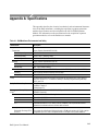
Appendix A: Specifications . . . . . . . . . . . . . . . . . . . . . . . . . . . . . . . . . . .
Appendix B: Accessories . . . . . . . . . . . . . . . . . . . . . . . . . . . . . . . . . . . . .
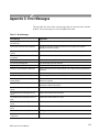
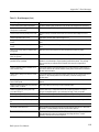
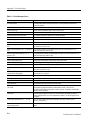
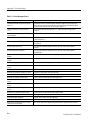
Appendix C: Error Messages . . . . . . . . . . . . . . . . . . . . . . . . . . . . . . . . .
DAS System User Manual
A–1
B–1
C–1
iii
Table of Contents
iv
Appendix D: Loading System Software . . . . . . . . . . . . . . . . . . . . . . . .
D–1
SCSI Hard Disk Format Utility . . . . . . . . . . . . . . . . . . . . . . . . . . . . . . . . . . . . . .
Running the SCSI Hard Disk Format Utility . . . . . . . . . . . . . . . . . . . . . . . .
SCSI Hard Disk Utility Main Menu . . . . . . . . . . . . . . . . . . . . . . . . . . . . . . .
Format Setup Menu . . . . . . . . . . . . . . . . . . . . . . . . . . . . . . . . . . . . . . . . . . . .
Change Swap Size Menu . . . . . . . . . . . . . . . . . . . . . . . . . . . . . . . . . . . . . . .
Bad Block List Display . . . . . . . . . . . . . . . . . . . . . . . . . . . . . . . . . . . . . . . . .
File System Make Utility . . . . . . . . . . . . . . . . . . . . . . . . . . . . . . . . . . . . . . . . . . .
Running the File System Make Utility . . . . . . . . . . . . . . . . . . . . . . . . . . . . .
File System Check Procedure . . . . . . . . . . . . . . . . . . . . . . . . . . . . . . . . . . . .
File System Install Utility . . . . . . . . . . . . . . . . . . . . . . . . . . . . . . . . . . . . . . . . . .
Installing Base System Software . . . . . . . . . . . . . . . . . . . . . . . . . . . . . . . . .
Installing Optional System Software . . . . . . . . . . . . . . . . . . . . . . . . . . . . . .
Installing Application Software . . . . . . . . . . . . . . . . . . . . . . . . . . . . . . . . . .
Removing Optional System Software or Application Software . . . . . . . . . .
Verifying Base, Optional, and Application Software . . . . . . . . . . . . . . . . . .
Optional System Software . . . . . . . . . . . . . . . . . . . . . . . . . . . . . . . . . . . . . . . . . .
Application Software . . . . . . . . . . . . . . . . . . . . . . . . . . . . . . . . . . . . . . . . . . . . . .
D–2
D–2
D–3
D–5
D–6
D–8
D–9
D–9
D–10
D–15
D–15
D–17
D–17
D–18
D–19
D–20
D–22
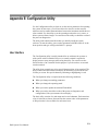
Appendix E: Configuration Utility . . . . . . . . . . . . . . . . . . . . . . . . . . . .
E–1
User Interface . . . . . . . . . . . . . . . . . . . . . . . . . . . . . . . . . . . . . . . . . . . . . . . . . . . .
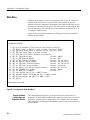
Main Menu . . . . . . . . . . . . . . . . . . . . . . . . . . . . . . . . . . . . . . . . . . . . . . . . . . . . . .
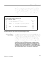
Display Hardware Configuration and Diagnostic Results . . . . . . . . . . . . . .
Save Image of Current System Software . . . . . . . . . . . . . . . . . . . . . . . . . . .
Restore Image of Saved System Software . . . . . . . . . . . . . . . . . . . . . . . . . .
Delete Saved Image of System Software . . . . . . . . . . . . . . . . . . . . . . . . . . .
Show Factory Default Network Configuration . . . . . . . . . . . . . . . . . . . . . . .
Set Operating Mode . . . . . . . . . . . . . . . . . . . . . . . . . . . . . . . . . . . . . . . . . . .
Set DAS Network Name . . . . . . . . . . . . . . . . . . . . . . . . . . . . . . . . . . . . . . . .
Set DAS Internet Address . . . . . . . . . . . . . . . . . . . . . . . . . . . . . . . . . . . . . . .
Set Network Subnet Mask . . . . . . . . . . . . . . . . . . . . . . . . . . . . . . . . . . . . . .
Set Gateway Internet Address . . . . . . . . . . . . . . . . . . . . . . . . . . . . . . . . . . . .
Set Default X Server Name . . . . . . . . . . . . . . . . . . . . . . . . . . . . . . . . . . . . . .
Set Default X Server Address . . . . . . . . . . . . . . . . . . . . . . . . . . . . . . . . . . . .
Set LANPCL Port Number . . . . . . . . . . . . . . . . . . . . . . . . . . . . . . . . . . . . . .
Set GPIB Port Number . . . . . . . . . . . . . . . . . . . . . . . . . . . . . . . . . . . . . . . . .
Update Terminal Flash ROM . . . . . . . . . . . . . . . . . . . . . . . . . . . . . . . . . . . .
Leave the Utility . . . . . . . . . . . . . . . . . . . . . . . . . . . . . . . . . . . . . . . . . . . . . .
E–1
E–2
E–2
E–3
E–4
E–5
E–5
E–6
E–6
E–7
E–7
E–7
E–7
E–8
E–8
E–9
E–9
E–12
Appendix F: User Service . . . . . . . . . . . . . . . . . . . . . . . . . . . . . . . . . . . .
F–1
Initial Inspection . . . . . . . . . . . . . . . . . . . . . . . . . . . . . . . . . . . . . . . . . . . . . . . . . .
Repacking for Shipment . . . . . . . . . . . . . . . . . . . . . . . . . . . . . . . . . . . . . . . . . . . .
Preventive Maintenance . . . . . . . . . . . . . . . . . . . . . . . . . . . . . . . . . . . . . . . . . . . .
Exterior Mainframe . . . . . . . . . . . . . . . . . . . . . . . . . . . . . . . . . . . . . . . . . . . .
Floppy Disk Drive . . . . . . . . . . . . . . . . . . . . . . . . . . . . . . . . . . . . . . . . . . . . .
Terminal . . . . . . . . . . . . . . . . . . . . . . . . . . . . . . . . . . . . . . . . . . . . . . . . . . . .
Module Configurations . . . . . . . . . . . . . . . . . . . . . . . . . . . . . . . . . . . . . . . . . . . .
Compatibility of Modules . . . . . . . . . . . . . . . . . . . . . . . . . . . . . . . . . . . . . . .
Configuration . . . . . . . . . . . . . . . . . . . . . . . . . . . . . . . . . . . . . . . . . . . . . . . .
F–1
F–1
F–2
F–2
F–2
F–3
F–3
F–3
F–4
DAS System User Manual
Table of Contents
Module Installation and Removal . . . . . . . . . . . . . . . . . . . . . . . . . . . . . . . . . . . .
Tools Required . . . . . . . . . . . . . . . . . . . . . . . . . . . . . . . . . . . . . . . . . . . . . . .
Removing the Top Cover and Card Cage Door . . . . . . . . . . . . . . . . . . . . . .
Installing a Module . . . . . . . . . . . . . . . . . . . . . . . . . . . . . . . . . . . . . . . . . . . .
Removing a Module . . . . . . . . . . . . . . . . . . . . . . . . . . . . . . . . . . . . . . . . . . .
Installing the GPIB Connector . . . . . . . . . . . . . . . . . . . . . . . . . . . . . . . . . . .
Installing Remote On/Off Options . . . . . . . . . . . . . . . . . . . . . . . . . . . . . . . .
Replacing the Line Fuse . . . . . . . . . . . . . . . . . . . . . . . . . . . . . . . . . . . . . . . . . . . .
Power-On Diagnostics . . . . . . . . . . . . . . . . . . . . . . . . . . . . . . . . . . . . . . . . . . . . .
Mainframe Diagnostics . . . . . . . . . . . . . . . . . . . . . . . . . . . . . . . . . . . . . . . . .
Terminal Diagnostics . . . . . . . . . . . . . . . . . . . . . . . . . . . . . . . . . . . . . . . . . .
Fault Isolation . . . . . . . . . . . . . . . . . . . . . . . . . . . . . . . . . . . . . . . . . . . . . . . . . . . .
Color Terminal Problems . . . . . . . . . . . . . . . . . . . . . . . . . . . . . . . . . . . . . . .
Incorrect Data Acquired . . . . . . . . . . . . . . . . . . . . . . . . . . . . . . . . . . . . . . . .
No Data Acquired . . . . . . . . . . . . . . . . . . . . . . . . . . . . . . . . . . . . . . . . . . . . .
No Data from Pattern Generator . . . . . . . . . . . . . . . . . . . . . . . . . . . . . . . . . .
No Data Printed To Printer Connected to Auxiliary Port . . . . . . . . . . . . . . .
No Data Sent to a Network File . . . . . . . . . . . . . . . . . . . . . . . . . . . . . . . . . .
No Data Printed to Network Printer . . . . . . . . . . . . . . . . . . . . . . . . . . . . . . .
Instrument Options . . . . . . . . . . . . . . . . . . . . . . . . . . . . . . . . . . . . . . . . . . . . . . . .
Power Cords . . . . . . . . . . . . . . . . . . . . . . . . . . . . . . . . . . . . . . . . . . . . . . . . .
F–11
F–11
F–11
F–13
F–16
F–16
F–17
F–18
F–19
F–19
F–19
F–19
F–20
F–21
F–21
F–22
F–22
F–22
F–23
F–23
F–24
Appendix G: DASdisk Utility . . . . . . . . . . . . . . . . . . . . . . . . . . . . . . . . .
G–1
PC System Requirements . . . . . . . . . . . . . . . . . . . . . . . . . . . . . . . . . . . . . . . . . . .
Installing DASdisk . . . . . . . . . . . . . . . . . . . . . . . . . . . . . . . . . . . . . . . . . . . . . . . .
Using DASdisk . . . . . . . . . . . . . . . . . . . . . . . . . . . . . . . . . . . . . . . . . . . . . . . . . . .
File Sets . . . . . . . . . . . . . . . . . . . . . . . . . . . . . . . . . . . . . . . . . . . . . . . . . . . . .
Change Operation . . . . . . . . . . . . . . . . . . . . . . . . . . . . . . . . . . . . . . . . . . . . .
Init Operation . . . . . . . . . . . . . . . . . . . . . . . . . . . . . . . . . . . . . . . . . . . . . . . .
List Operation . . . . . . . . . . . . . . . . . . . . . . . . . . . . . . . . . . . . . . . . . . . . . . . .
Dir Operation . . . . . . . . . . . . . . . . . . . . . . . . . . . . . . . . . . . . . . . . . . . . . . . .
Unpack Operation . . . . . . . . . . . . . . . . . . . . . . . . . . . . . . . . . . . . . . . . . . . . .
Pack Operation . . . . . . . . . . . . . . . . . . . . . . . . . . . . . . . . . . . . . . . . . . . . . . .
Add Operation . . . . . . . . . . . . . . . . . . . . . . . . . . . . . . . . . . . . . . . . . . . . . . . .
Remove Operation . . . . . . . . . . . . . . . . . . . . . . . . . . . . . . . . . . . . . . . . . . . .
Read Operation . . . . . . . . . . . . . . . . . . . . . . . . . . . . . . . . . . . . . . . . . . . . . . .
Write Operation . . . . . . . . . . . . . . . . . . . . . . . . . . . . . . . . . . . . . . . . . . . . . . .
Delete Operation . . . . . . . . . . . . . . . . . . . . . . . . . . . . . . . . . . . . . . . . . . . . . .
Quit Operation . . . . . . . . . . . . . . . . . . . . . . . . . . . . . . . . . . . . . . . . . . . . . . .
Optional Command-Line Switches . . . . . . . . . . . . . . . . . . . . . . . . . . . . . . . .
G–1
G–1
G–2
G–2
G–3
G–3
G–3
G–3
G–3
G–4
G–5
G–5
G–5
G–6
G–7
G–7
G–8
Glossary
Index
DAS System User Manual
v
Table of Contents
List of Figures
vi
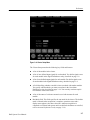
Figure 1–1: Master Mainframe and Expansion Mainframes . . . . . . .
Figure 1–2: Expansion Mainframe Stacked
on Master Mainframe . . . . . . . . . . . . . . . . . . . . . . . . . . . . . . . . . . . .
Figure 1–3: Master and Expansion Mainframe Connections . . . . . . .
1–6
1–7
1–14
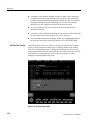
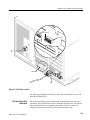
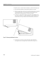
Figure 2–1: Front View of the DAS Mainframe . . . . . . . . . . . . . . . . . .
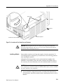
Figure 2–2: Rear View of the DAS Master Mainframe . . . . . . . . . . . .
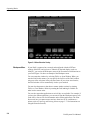
Figure 2–3: Menu Selection Overlay . . . . . . . . . . . . . . . . . . . . . . . . . . .
Figure 2–4: Workspace Menu (on Tektronix X Terminals) . . . . . . . . .
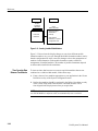
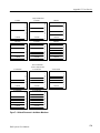
Figure 2–5: Setup Menus for Each Module . . . . . . . . . . . . . . . . . . . . .
Figure 2–6: Module Display Menus . . . . . . . . . . . . . . . . . . . . . . . . . . . .
Figure 2–7: Menu Selection Overlay . . . . . . . . . . . . . . . . . . . . . . . . . . .
Figure 2–8: Set Date/Time Overlay . . . . . . . . . . . . . . . . . . . . . . . . . . . .
Figure 2–9: On-Screen Buttons . . . . . . . . . . . . . . . . . . . . . . . . . . . . . . .
Figure 2–10: Function Keys Map to the Function Key Legends . . . .
Figure 2–11: Channel Menu . . . . . . . . . . . . . . . . . . . . . . . . . . . . . . . . . .
Figure 2–12: Clock Menu . . . . . . . . . . . . . . . . . . . . . . . . . . . . . . . . . . . .
Figure 2–13: Trigger Menu . . . . . . . . . . . . . . . . . . . . . . . . . . . . . . . . . . .
Figure 2–14: State Menu . . . . . . . . . . . . . . . . . . . . . . . . . . . . . . . . . . . . .
Figure 2–15: Timing Menu . . . . . . . . . . . . . . . . . . . . . . . . . . . . . . . . . . .
Figure 2–16: Split-Screen Menu . . . . . . . . . . . . . . . . . . . . . . . . . . . . . . .
2–2
2–3
2–4
2–5
2–7
2–9
2–12
2–13
2–16
2–20
2–25
2–26
2–27
2–28
2–30
2–32
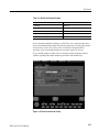
Figure 3–1: System Configuration Menu . . . . . . . . . . . . . . . . . . . . . . .
Figure 3–2: Multimodule Operation Sequence . . . . . . . . . . . . . . . . . . .
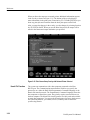
Figure 3–3: Cluster Definition Overlay . . . . . . . . . . . . . . . . . . . . . . . . .
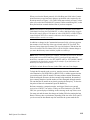
Figure 3–4: Cluster Setup Menu . . . . . . . . . . . . . . . . . . . . . . . . . . . . . .
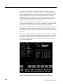
Figure 3–5: Signal Definition Overlay . . . . . . . . . . . . . . . . . . . . . . . . . .
Figure 3–6: 92C02 Module External Event Pins . . . . . . . . . . . . . . . . .
Figure 3–7: Time Correlation Between Two Acquisition
Modules in a Cluster . . . . . . . . . . . . . . . . . . . . . . . . . . . . . . . . . . . . .
Figure 3–8: Correlation Definition Overlay . . . . . . . . . . . . . . . . . . . . .
Figure 3–9: Autorun Definition Overlay . . . . . . . . . . . . . . . . . . . . . . . .
Figure 3–10: System Monitor Menu . . . . . . . . . . . . . . . . . . . . . . . . . . .
Figure 3–11: Save/Restore Menu: Save Setup Operations . . . . . . . . .
Figure 3–12: Save/Restore Menu: Save Refmem Operations . . . . . . .
Figure 3–13: Save/Restore Menu: Restore Setup Operations . . . . . . .
3–2
3–4
3–5
3–7
3–10
3–12
3–15
3–15
3–18
3–21
3–24
3–26
3–28
DAS System User Manual
Table of Contents
DAS System User Manual
Figure 3–14: Restore Formation Overlay . . . . . . . . . . . . . . . . . . . . . . .
Figure 3–15: Save/Restore Menu: Delete Operations . . . . . . . . . . . . .
Figure 3–16: Disk Services Menu: Copy File Operation . . . . . . . . . . .
Figure 3–17: Disk Services Menu: Delete File Operation . . . . . . . . . .
Figure 3–18: Symbol Editor Menu (Pattern Symbol
Table Displayed) . . . . . . . . . . . . . . . . . . . . . . . . . . . . . . . . . . . . . . . .
Figure 3–19: Symbol Editor Menu (Range Symbol
Table Displayed) . . . . . . . . . . . . . . . . . . . . . . . . . . . . . . . . . . . . . . . .
Figure 3–20: File Functions Overlay (Symbol Editor Menu) . . . . . . .
Figure 3–21: Search Definition Overlay (Symbol Editor Menu) . . . .
Figure 3–22: Communications Menu . . . . . . . . . . . . . . . . . . . . . . . . . .
Figure 3–23: LAN Overlay . . . . . . . . . . . . . . . . . . . . . . . . . . . . . . . . . . .
Figure 3–24: Print Screen Setup Overlay . . . . . . . . . . . . . . . . . . . . . . .
Figure 3–25: Print Screen Setup Overlay with Network
Printer Selected . . . . . . . . . . . . . . . . . . . . . . . . . . . . . . . . . . . . . . . . .
Figure 3–26: Communications Menu with the Kermit
File Transfer Protocol . . . . . . . . . . . . . . . . . . . . . . . . . . . . . . . . . . . .
Figure 3–27: The Diagnostics Menu . . . . . . . . . . . . . . . . . . . . . . . . . . .
Figure 3–28: Set Date/Time Overlay . . . . . . . . . . . . . . . . . . . . . . . . . . .
Figure 3–29: Boot Option Overlay . . . . . . . . . . . . . . . . . . . . . . . . . . . . .
Figure 3–30: Version Menu . . . . . . . . . . . . . . . . . . . . . . . . . . . . . . . . . . .
Figure 3–31: Creating Variable Width Modules . . . . . . . . . . . . . . . . .
Figure 3–32: Selecting Module Formations . . . . . . . . . . . . . . . . . . . . .
Figure 3–33: Print Screen Tool of the Workspace Menu . . . . . . . . . . .
3–29
3–30
3–33
3–35
3–54
3–55
3–56
3–57
3–59
3–62
3–63
3–73
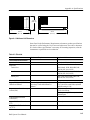
Figure A–1: Mainframe Unit Dimensions . . . . . . . . . . . . . . . . . . . . . . .
A–3
Figure D–1: DIP Switch Location . . . . . . . . . . . . . . . . . . . . . . . . . . . . .
Figure D–2: SCSI Hard Disk Format Utility Main Menu . . . . . . . . . .
D–3
D–4
Figure E–1: Configuration Utility, Main Menu . . . . . . . . . . . . . . . . . .
Figure E–2: Configuration Utility, Hardware Configuration
and Diagnostic Results . . . . . . . . . . . . . . . . . . . . . . . . . . . . . . . . . . .
Figure E–3: Configuration Utility, Factory Default
Network Configuration . . . . . . . . . . . . . . . . . . . . . . . . . . . . . . . . . .
E–2
E–6
Figure F–1: Module Placement in the Master Mainframe . . . . . . . . .
Figure F–2: Module Placement in the Expansion Mainframe . . . . . .
Figure F–3: Removing the Mainframe Top Cover . . . . . . . . . . . . . . . .
Figure F–4: Locations of Card Cage Door and Fasteners . . . . . . . . . .
Figure F–5: Installing the GPIB Connector . . . . . . . . . . . . . . . . . . . . .
F–9
F–10
F–12
F–13
F–18
3–40
3–42
3–43
3–45
3–46
3–48
3–51
3–52
E–3
vii
Table of Contents
List of Tables
viii
Table 1–1: Power for Master Mainframes . . . . . . . . . . . . . . . . . . . . . .
Table 1–2: Power for Expansion Mainframes . . . . . . . . . . . . . . . . . . .
Table 1–3: Power for Modules (with Probes) . . . . . . . . . . . . . . . . . . . .
Table 1–4: Terminal Default Boot Parameters . . . . . . . . . . . . . . . . . .
Table 1–5: 9-pin DCE-to-25-Pin DTE Cable Connections . . . . . . . . .
Table 1–6: 9-pin DCE-to-25-Pin DCE Cable Connections . . . . . . . . .
Table 1–7: Baud Rate DIP Switches . . . . . . . . . . . . . . . . . . . . . . . . . . .
Table 1–8: Acquisition and Pattern Generation Modules . . . . . . . . . .
1–9
1–9
1–10
1–13
1–16
1–16
1–18
1–19
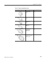
Table 2–1: Three-Button Mouse Description . . . . . . . . . . . . . . . . . . . .
Table 2–2: On-Screen Menu Buttons . . . . . . . . . . . . . . . . . . . . . . . . . .
Table 2–3: On-Screen Macro Buttons . . . . . . . . . . . . . . . . . . . . . . . . . .
Table 2–4: Keyboard Equivalents . . . . . . . . . . . . . . . . . . . . . . . . . . . . .
2–11
2–17
2–18
2–18
Table 3–1: Signal Event Resources . . . . . . . . . . . . . . . . . . . . . . . . . . . .
Table 3–2: External Event I/O Connections . . . . . . . . . . . . . . . . . . . .
Table 3–3: Asynchronous External Events . . . . . . . . . . . . . . . . . . . . . .
Table 3–4: Print Screen Output Formats . . . . . . . . . . . . . . . . . . . . . . .
3–9
3–13
3–13
3–51
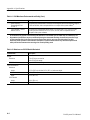
Table A–1: DAS Mainframe Environmental and Safety . . . . . . . . . .
Table A–2: Mainframe and 92C02 Module Mechanical . . . . . . . . . . .
Table A–3: Electrical . . . . . . . . . . . . . . . . . . . . . . . . . . . . . . . . . . . . . . .
Table A–4: Standard Electrical Interfaces . . . . . . . . . . . . . . . . . . . . . .
Table A–5: Discrete I/O Signals . . . . . . . . . . . . . . . . . . . . . . . . . . . . . .
Table A–6: Terminal Physical Dimensions . . . . . . . . . . . . . . . . . . . . . .
Table A–7: Terminal Keyboard Physical Dimensions . . . . . . . . . . . . .
A–1
A–2
A–3
A–4
A–5
A–6
A–6
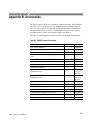
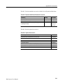
Table B–1: DAS/XP Standard Accessories . . . . . . . . . . . . . . . . . . . . . .
Table B–2: DAS/NT Standard Accessories . . . . . . . . . . . . . . . . . . . . .
Table B–3: Expansion Mainframe Standard Accessories . . . . . . . . . .
Table B–4: Optional Accessories . . . . . . . . . . . . . . . . . . . . . . . . . . . . . .
B–1
B–2
B–3
B–3
Table C–1: Error Messages . . . . . . . . . . . . . . . . . . . . . . . . . . . . . . . . . .
C–1
Table D–1: Phase 1 File System Check Error Messages . . . . . . . . . . .
Table D–2: Phase 2 File System Check Error Messages . . . . . . . . . . .
Table D–3: Phase 3 File System Check Error Messages . . . . . . . . . . .
D–11
D–12
D–13
DAS System User Manual
Table of Contents
DAS System User Manual
Table D–4: Phase 4 File System Check Error Messages . . . . . . . . . . .
Table D–5: Phase 5 File System Check Error Messages . . . . . . . . . . .
D–13
D–14
Table E–1: System Software vs Operating Modes . . . . . . . . . . . . . . . .
E–6
Table F–1: Card Placement Guidelines: Master Mainframe . . . . . . .
Table F–2: Card Placement Guidelines: Expansion Mainframe . . . .
Table F–3: System Unit Fuse Replacement . . . . . . . . . . . . . . . . . . . . .
Table F–4: Terminal Default Boot Parameters . . . . . . . . . . . . . . . . . .
Table F–5: DAS/XP System Options . . . . . . . . . . . . . . . . . . . . . . . . . . .
Table F–6: DAS/NT System Options . . . . . . . . . . . . . . . . . . . . . . . . . .
Table F–7: Power Cord Identification . . . . . . . . . . . . . . . . . . . . . . . . .
F–8
F–8
F–18
F–20
F–23
F–24
F–24
Table G–1: Screen Colors vs Switch Word . . . . . . . . . . . . . . . . . . . . .
Table G–2: Valid Color Characters for DASdisk . . . . . . . . . . . . . . . .
Table G–3: Examples of DASdisk Commands . . . . . . . . . . . . . . . . . .
G–8
G–9
G–10
ix
Table of Contents
x
DAS System User Manual
General Safety Summary
Review the following safety precautions to avoid injury and prevent damage to
this product or any products connected to it.
Only qualified personnel should perform service procedures.
Injury Precautions
Use Proper Power Cord
To avoid fire hazard, use only the power cord specified for this product.
Ground the Product
This product is grounded through the grounding conductor of the power cord. To
avoid electric shock, the grounding conductor must be connected to earth
ground. Before making connections to the input or output terminals of the
product, ensure that the product is properly grounded.
Do Not Operate Without
Covers
To avoid electric shock or fire hazard, do not operate this product with covers or
panels removed.
Use Proper Fuse
To avoid fire hazard, use only the fuse type and rating specified for this product.
Do Not Operate in
Wet/Damp Conditions
Do Not Operate in
Explosive Atmosphere
Avoid Exposed Circuitry
To avoid electric shock, do not operate this product in wet or damp conditions.
To avoid injury or fire hazard, do not operate this product in an explosive
atmosphere.
To avoid injury, remove jewelry such as rings, watches, and other metallic
objects. Do not touch exposed connections and components when power is
present.
Product Damage Precautions
Use Proper Power Source
DAS System User Manual
Do not operate this product from a power source that applies more than the
voltage specified.
xi
General Safety Summary
Use Proper Voltage
Setting
Provide Proper Ventilation
Do Not Operate With
Suspected Failures
Before applying power, ensure that the line selector is in the proper position for
the power source being used.
To prevent product overheating, provide proper ventilation.
If you suspect there is damage to this product, have it inspected by qualified
service personnel.
Safety Terms and Symbols
Terms in This Manual
These terms may appear in this manual:
WARNING. Warning statements identify conditions or practices that could result
in injury or loss of life.
CAUTION. Caution statements identify conditions or practices that could result in
damage to this product or other property.
Terms on the Product
These terms may appear on the product:
DANGER indicates an injury hazard immediately accessible as you read the
marking.
WARNING indicates an injury hazard not immediately accessible as you read the
marking.
CAUTION indicates a hazard to property including the product.
Symbols on the Product
The following symbols may appear on the product:
DANGER
High Voltage
xii
Protective Ground
(Earth) Terminal
ATTENTION
Refer to
Manual
Double
Insulated
DAS System User Manual
General Safety Summary
Certifications and Compliances
CSA Certified Power
Cords
Compliances
DAS System User Manual
CSA Certification includes the products and power cords appropriate for use in
the North America power network. All other power cords supplied are approved
for the country of use.
Consult the product specifications for IEC Installation Category, Pollution
Degree, and Safety Class.
xiii
General Safety Summary
xiv
DAS System User Manual
Preface
The DAS System User Manual is the main reference manual for the Digital
Analysis System (DAS). It includes an overview of the system, basic
installation information, a tutorial for new users, and reference information
for system-level menus.
The manual is part of the Digital Analysis System (DAS) documentation set. In
addition to the DAS System User Manual, you should consult the following
documentation to get the most out of your logic analysis system:
H
The 92A96 & 92C96 Module User Manual provides detailed information on
the 92A96 and 92C96 Data Acquisition Modules. Consult this manual for
information on the Setup and Display menus for the acquisition modules and
for information on connecting the probes to the system-under-test.
H
A series of other module user manuals that provide detailed information on
the data acquisition and pattern generation modules available for use with
DAS systems. Consult the individual manuals for information on the Setup
and Display menus for each module and for information on connecting the
probes to the system-under-test.
H
A series of microprocessor disassembler instruction manuals that describe the
various microprocessor support packages available with the DAS systems.
H
A technician’s reference manual provides service information for qualified
service technicians to isolate problems to the module level.
H
A series of application software user manuals that accompany the various
software support packages.
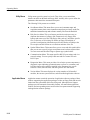
How to Use This Manual
The DAS System User Manual consists of the following:
DAS System User Manual
H
Getting Started. This chapter briefly describes the DAS and, provides
installation instructions, and information for first-time users.
H
Operating Basics. This chapter provides a functional overview of the DAS. It
also provides a tutorial for new users who are unfamiliar with the operation
of the DAS.
H
Reference. This chapter contains reference information on the system-level
menus and guidelines for multimodule operation.
xv
Preface
H
Appendices. The appendices contain information on the product specifications (acquisition and pattern generation module specifications are listed in
the respective module user manuals), product options and accessories, error
messages, software installation procedures, software configuration procedures, the DASdisk utility, and user service procedures. User service
procedures provide guidelines for changing the configuration of the
acquisition and pattern generation modules.
H
Glossary and Index.
If your are new to the DAS, you should read the Getting Started and Operating
Basics chapters before using the DAS for the first time. You should also review
the acquisition and pattern generation module user manuals to become familiar
with the capabilities of the individual modules of the DAS.
Manual Conventions
The following terms and conventions are used throughout this manual:
H
The term mainframe refers to the mechanical chassis of the DAS.
H
The term system refers to the entire digital analysis system including, the
mainframe, terminal, and probes.
H
The term terminal refers to the color X terminal. If you have a DAS/NT
system, your DAS can be connected to a network and be controlled by
X11/R4 workstations in addition to the X terminals.
H
The term module refers to either to the acquisition or pattern generation
circuit card.
H
The term 92C96 refers to the 92C96 Data Acquisition Module. The 92C96 is
the configurable 92A96 Data Acquisition Module. The 92C96 functions
identically to the 92A96 Data Acquisition Module.
H
The tilde symbol (~) represents active low signals.
Earlier references to the DAS included the following terms:
xvi
H
DAS 9200. The nomenclature for earlier versions of the digital analysis system.
H
DAS 9221, DAS 9200/SE. The various names assigned to the mainframe.
H
9200T and 9201T. These were the names of early (non-X terminal) versions
of the standard terminals for the DAS.
DAS System User Manual
Getting Started
This chapter introduces you to the Digital Analysis System (DAS) and provides
instructions for starting to use the system.
Product Description
The Digital Analysis System (DAS) is a highly modular family of digital
analysis tools, including a mainframe, a color terminal, acquisition and pattern
generation modules, application software packages, and probes. You select the
tools and configure them to suit your needs. The result is a custom digital
analysis system tailored to your own applications.
You can use the DAS in one of two ways, as a stand-alone digital analysis
system, or as an networked digital analysis system. The DAS/NT is the
networked version while the DAS/XP is the stand-alone version.
When used in the stand-alone configuration, the DAS can be connected with
peripheral printer or a host computer. The color X terminal displays the
interactive-control menus. When connected to a network, the DAS can be
controlled by a workstation (refer to the 92XTerm User Manual for more
information on using a DAS/NT on a network). When connected to a host
computer, the DAS supports transfers of acquisition/stimulation data and
instrument setup data.
The DAS comes standard with a local area network (LAN) interface. GPIB and
RS-232 remote control is also available. When connected to a host computer, the
following capabilities are available:
H
File transfers via ftp (LAN) or Kermit (RS-232)
H
Remote control via LAN (92LANP and PCL), GPIB, and RS-232
H
Networked operation with interactive control and data display on X
compatible workstations
The DAS supports a Programmatic Command Language (PCL) that serves as an
alternative to the keyboard and menu interface. The PCL commands allow you to
start and stop acquisition, to save, load, and transfer files, and to query the
mainframe for a variety of status and error information. Data can be processed
either by the DAS or the host computer. When data processing is performed by
the host, the DAS serves as a source for raw or partially processed data.
DAS System User Manual
1–1
Getting Started
Mainframe Hardware
The DAS mainframe provides computing power, input/output features, and mass
storage for the internal acquisition and pattern generation modules. You can
install several different instrument modules inside the mainframe depending on
your needs. An Expansion mainframe (DAS 92E9), which provides extra slots
for additional modules, is also available.
The DAS/NT can be identified by the NT sticker on the front panel. Similarly
the DAS/XP has a XP sticker. Earlier versions of the DAS have an SE sticker.
The standard display device for the DAS/XP is a color X window, terminal with
a mouse-driven interface. A set of nested, interactive menus let you define the
contents of the system you need, enter parameters and data, and control the
system outputs.
The DAS mainframe consists of the following major internal components:
DAS Mainframe with
Option 04
H
Mechanical chassis
H
Hard and floppy disk drives
H
40 MHz 68EC030 CPU
H
RS-232 ports
H
Power supply (100 watts per slot average)
H
Local Area Network (LAN) interface
H
External input and output connection
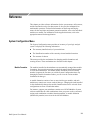
An option to the DAS mainframe, Option 04, allows the mainframe to satisfy the
German electromagnetic interference (EMI) requirements.
DAS Systems Prior to January 1, 1996. DAS mainframes equipped with Option 04
that were sold prior to January 1, 1996 satisfied the German electromagnetic
interference (EMI) requirements (VDE 0871, Class B). This VDE option applied
to mainframes set for 230 V operation only; operation at 115 V exceeds
component ratings. A mainframe with Option 04 included the following items:
1–2
H
Conductive elastic between the front facade and the media mount
H
Rear-panel probe shields
H
EMI gasket material on the edges of the base plate
H
Clip for holding the power supply tightly against the inside of the rear panel
H
Probe clamps for holding probes to the rear panel
DAS System User Manual
Getting Started
H
Conductive paint on the inside of the top cover and base plate that makes
connection to the EMI gasket material along the edges of the base plate
H
Screen material on the front facade and top cover
H
EMI gasket material on the inside-rear edge of the top cover
Follow these precautionary guidelines when using a mainframe equipped with
Option 04:
H
Avoid scratching any surface coated with conductive paint
H
Avoid bending or tearing gasket material along edges of base plate and take
care not to snag clothing on gasket material
Remove only the shields that correspond to probes or cables being attached;
unnecessary removal of shields increases EMI radiation. To remove a rear-panel
probe shield, you will need to remove two top screws, and then the two screws
for the adjacent shield. After removing the shield, replace the screws attaching
the adjacent shield.
DAS Systems After January 1, 1996. Newer DAS mainframes with Option 04 meet
Directive 89/336/EEC for electromagnetic compatibility. Option 04 applies to
mainframes set for 230 V operation only; operation at 115 V exceeds component
ratings. A mainframe with Option 04 includes a 230 V line filter to eliminate or
reduce electromagnetic interference.
Mechanical Chassis
The chassis provides mechanical connection and cooling for all mainframe
components and options. The internal acquisition and pattern generation modules
reside in a card cage; associated probes connect to installed modules through
openings in the rear of the chassis.
Controller Board
The Controller board provides the DAS with computing resources and the means
for setting up hardware for the system and individual modules. The Controller
board also provides access to mass storage and communication interfaces. The
Controller board resides in slot 0 of the mainframe.
Backplane Board
This board provides the mechanical and electrical connection between the
Controller board and the slots that accept DAS acquisition and pattern generation
modules. Signals are carried on bus structures, some of which extend beyond this
mainframe to expansion mainframes.
DAS System User Manual
1–3
Getting Started
Hard and Floppy Disk
Drives
The mass-storage device in the mainframe is a hard disk drive. You can order
your mainframe equipped with a removable hard disk drive so that setup and
data files can be secured in a vault overnight. The system software is installed on
the hard disk and all other files are eventually stored here (such as setups and
reference memories).
CAUTION. Do not disconnect or remove the removable hard disk drive while the
system is powered. Doing so will damage the hard disk or corrupt the file system.
A 3.5-inch, high-density, 1.44-megabyte floppy disk drive is standard in the
mainframe. The floppy disk drive is used for loading application software,
copying files for use on other DAS mainframes, making/restoring backup files,
and transferring data to host computers. A light on the front of the floppy disk
drive indicates when a floppy disk is being accessed. Backup system software
can also be loaded onto the hard disk from disks inserted in the floppy disk
drive. Backup procedures are described with on-screen steps that inform you
how to proceed.
RS-232 Ports
LAN Interface
I/O Port
1–4
The mainframe supports three RS-232 communication ports accessible on the
rear panel:
H
The terminal port connects the mainframe to the display terminal. Baud rates
are 38400 (default), 19200, 9600, 4800, 2400, 1200, 600, 300, and 110.
H
The host port connects the mainframe to RS-232-compatible host computer
systems. Baud rates are 38400, 19200, 9600 (default), 4800, 2400, 1200,
600, 300, and 110.
H
The auxiliary port provides the connection to other RS-232-compatible
devices (for example, a printer). The port sends out 8 bits per character and
no parity (parity is off). Baud rates are 38400, 19200, 9600 (default), 4800,
2400, 1200, 600, 300, and 110.
The local area network interface connects the mainframe to the X window
terminal or to a network. The LAN software provides you with a means to
transfer files between the DAS and a workstation through ftp (file transfer
protocol) and other protocols. An optional 92LANP application software product
allows you to remotely control the DAS through the LAN interface.
The 92C02 GPIB/Expansion Module provides an optional GPIB interface as
well as an interface to the DAS 92E9 Expansion mainframe. Since Direct
Memory Access (DMA) capability is provided only in the Master mainframe
(not in an Expansion mainframe), these I/O boards must reside in slot 8 of the
Master mainframe card cage.
DAS System User Manual
Getting Started
A 37-pin connector allows you to monitor or drive external devices with the
optional 92PORT application software.
Power Supply
The power supply module supplies the power for all mainframe components. This
supply is capable of delivering up to 500 watts from a 115 VAC single-phase power
source using the 15 A power cord Option 1A (400 watts with the standard 12 A
power cord). If you use a 230 VAC power source with power cord Options A1-A5,
the supply delivers up to 575 watts. When you use the three-phase power source
(Option 1B power cord), the supply is capable of delivering approximately
700 watts.
External Event
Connections
The optional 92C02 GPIB/Expansion module has a set of pins that provide
external event I/O signals. The External Event In pin accepts a TTL-level signal
from an external source. The received event can be monitored by (or can control)
other instrument modules according to selections that you make in the Signal
Definition overlay (Cluster Setup menu).
The External Event Out pin passes a TTL-level event signal from a specified
DAS to an external component for use as an arming or triggering signal. You can
use the event out signal to trigger an oscilloscope or to stop, start, or trigger a
separate DAS system.
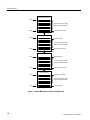
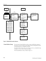
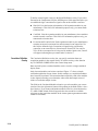
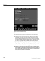
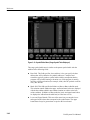
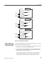
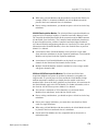
Expansion Mainframe
The DAS 92E9 Expansion mainframe provides additional slot space for
acquisition and pattern generation modules. Up to three Expansion mainframes
can be added to the Master mainframe. A Master mainframe and three Expansion
mainframes provide a total of 28 slots. Both Expansion and Master mainframes
use the same mechanical chassis, back plane, and power supply; however, the
Expansion mainframe does not include the disk drives, or the power switch. In
an Expansion mainframe, an Expansion Slave board takes the place of the
Master mainframe Controller board (see Figure 1–1).
In a fully-expanded system, the Master mainframe and Expansion mainframes
1 and 2 require a 92C02 Module in slot 8 of each mainframe.
If one Expansion mainframe is used with the Master mainframe, it can be placed
on top of the Master mainframe as in Figure 1–2; the Master mainframe can only
support the weight of one Expansion mainframe. When using two or three
Expansion mainframes, all mainframes must be vertically rackmounted; the
Master mainframe must be positioned as the lowest mainframe in the rack. For
complete details on rackmounting, refer to the document Option 05: Rackmount
Installation Instructions.
DAS System User Manual
1–5
Getting Started
Expansion Mainframe 3
Slot 35
8 slots for Acquisition and/or
Pattern Generation Modules
Slot 27
Expansion Slave Board
Expansion Cable
Expansion Mainframe 2
Slot 26
Expansion Board
7 slots for Acquisition and/or
Pattern Generation Modules
Slot 18
Expansion Slave Board
Expansion Cable
Expansion Mainframe 1
Expansion Board
Slot 17
7 slots for Acquisition and/or
Pattern Generation Modules
Expansion Slave Board
Slot 9
Expansion Cable
Master Mainframe
Slot 8
Expansion or Exp/GPIB
6 slots for Acquisition and/or
Pattern Generation Modules
Slot 0
Controller Board
Figure 1–1: Master Mainframe and Expansion Mainframes
1–6
DAS System User Manual
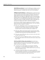
Getting Started
Acquisition Data Probe
Expansion
Mainframe
Master
Mainframe
Pattern Generation
Data Probe
System under Test
Figure 1–2: Expansion Mainframe Stacked on Master Mainframe
Installation
Most DAS mainframes are shipped from the factory with acquisition or pattern
generation cards already installed. Besides connecting the entire system, all you
have to do is connect the probes and power. If you ordered additional cards
separate from the mainframe, you can install them yourself. This section
describes how to install a system. To configure and install any additional
modules in the mainframe, refer to Appendix F: User Service.
Always read all guidelines, warnings, and cautions before attempting any
installation procedures. Also, check to make sure the mainframe power cord is
the proper rating for the configuration of cards you will be using.
The basic steps to install your logic analyzer follow:
1. Determine the power requirements for your mainframe and terminal (refer to
Power Requirements).
2. Determine the best locations for the mainframe and the terminal (refer to Site
Considerations on page 1–11).
3. Connect the power cord to the mainframe; connect the power cord to the
appropriate power source.
4. Connect the terminal to the mainframe (refer to Mainframe Connections on
page 1–14).
5. Connect the probes to the acquisition or pattern generation module (refer to
your module user manual for instructions on connecting the probes).
6. Connect the probes to the system-under-test.
DAS System User Manual
1–7
Getting Started
Power Requirements
The mainframe and terminal should connect to a power source that meets the
requirements stated in this section. The mainframe must be supplied with a properly
rated power cord. The mainframe power requirements depend on the number and
type of modules installed. To determine which power source your mainframe is set
to use, check the line voltage indicator on the rear panel of the mainframe.
Terminal Power Requirements. The color terminal requires a power source that
allows one-cycle surge currents of less than 30 A.
Mainframe Power Requirements. The Master mainframe and Expansion mainframes support different numbers of acquisition and pattern generation cards
based on the type of power cord/supply being used with each mainframe. The
standard 12 A power cord should be used for mainframe configurations drawing
less than 400 watts (12 A/115 V) and for Expansion mainframes drawing less
than 475 watts. When the configuration of cards in the mainframe requires more
power, a higher-current power cord must be used (refer to Tables 1–1 and 1–2). If
installed cards require more than 700 watts (750 in Expansion mainframes), the
DAS will automatically shut off. If the power requirements of the cards installed in
the mainframe exceed the power cord and power supply configuration, the DAS
also automatically shuts off. Contact your Tektronix field service representative for
assistance in determining the proper power supply or power cord configuration.
NOTE. If you install the 15 A power cord Option 1A, be sure to affix the label
supplied with the power cord. This label should be positioned directly to the
right of the power cord connector on the rear panel; the label should be placed
over the existing description that reads: 1900 VA MAX., FREQ. 48-63 Hz.
The maximum continuous current that each Master or Expansion mainframe can
draw is 15 A; the one-cycle surge current is 25 A nominal. Total line current for a
mainframe with three Expansion mainframes can be up to 60 A @ 115 V line
selection (40A @ 230 V). For a system using the maximum of four mainframes, the
power source must be capable of supplying the maximum amount of line current.
When the system is connected to a 230 V power source, the 230 V power cord
must be used. The DAS is specified to draw no more than 10 A when set for
230 V operation. When the DAS is connected to a three-phase power source, the
mainframe is specified to draw no more than 8 A on any phase; the three phase
power cord is permanently attached to the power supply. If it becomes necessary to
upgrade your power supply, contact your nearest Tektronix field service center.
1–8
DAS System User Manual
Getting Started
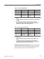
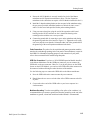
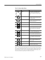
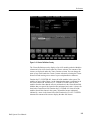
Table 1–1: Power for Master Mainframes
Watts
Voltage
Option
Source
400 W
105 V - 127 V
Std.
115 V, 12 A
500 W
105 V - 127 V 1
Opt. 1A
115 V, 15 A
575 W
200 V - 250 V
Opt. A1 - Opt. A5
230 V, 10 A
700 W 2
200 V - 250 V
(phase to phase)
Opt. 1B
(three-phase) 3
120/208 V, 8 A
1
Operation at a low line of 90 V is possible if the card-cage load is reduced to 425 W
or less.
2
The 3-phase 700 W power supply option 1B was discontinued effective SN B061162
and above.
3
The three-phase load is Y-connected. A maximum of 15 A at three times the
frequency may flow into the neutral conductor. A switch or circuit breaker at the
installation site is required by some international standards.
Table 1–2: Power for Expansion Mainframes
Watts
Voltage
Option
Source
475 W
105 V - 127 V
Std.
115 V, 12 A
575 W
105 V - 127 V 1
Opt. 1A
115 V, 15 A
650 W
200 V - 250 V
Opt A1 - Opt A5
230 V, 10 A
750 W 2
200 V - 250 V
(phase to phase)
Opt. 1B
(three-phase) 3
120/208 V, 8A
1
Operation at a low line of 90 V is possible if the card-cage load is reduced to
425 W or less.
2
The 3-phase 750 W power supply option 1B was discontinued SN B061162 and
above.
3
The three-phase load is Y-connected. A maximum of 15 A at three times the
frequency may flow into the neutral conductor. A switch or circuit breaker at the
installation site is required by some international standards.
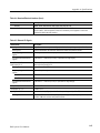
Susceptibility to Dropped Cycles in Power Source. The mainframe power supply
will maintain the DC voltage levels within the specified limits when the AC
power is removed for 16 ms or less. However, the mainframe will perform a
shutdown anytime the AC power is removed longer than 20 ms.
DAS System User Manual
1–9
Getting Started
If the intended installation site is susceptible to dropped cycles in the power
source, it is strongly recommended that a line-conditioning device be installed to
help prevent dropped cycles. The line-conditioning device should be specified to
handle line currents being drawn by the mainframe; for line currents, refer to
Mainframe Power Requirements on page 1–8.
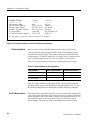
Module Power Requirements. Different combinations of modules requires that
different amounts of power be supplied by the Master mainframe or Expansion
mainframe. Some combinations may cause the line current to exceed the limits
of the power cord and power supply being used.
To determine which power cord/supply is required, check the terminal display
during power-on for a message describing the total wattage for the modules
currently installed in each attached mainframe. (Note: This power-on message is
erased after the Menu Selection overlay displays.) Compare the total card
wattage requirements (listed in Table 1–3) with the available mainframe power
listed in Tables 1–1 and 1–2. If the installed modules require more power than is
available from your current power cord/supply, you must upgrade the mainframe
to meet those requirements.
NOTE. If you changed the configuration of cards in the mainframe since the last
power-down, verify that the current power cord/supply supports the new
configuration. If you plan to add other modules to your system later, check the
power values in Tables 1–1, 1–2, and 1–3 to ensure that the total wattage
required by the new configuration can be supplied by your current mainframe
power cord/supply.
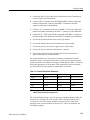
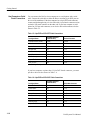
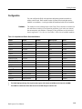
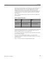
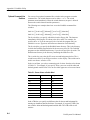
Table 1–3 lists the power consumed for each module. This table can also be used
when calculating the amount of power required for your specific configurations.
For example, assume a mainframe contains the following modules: one 92A16,
two 92A16Es, one 92S16, and one 92S32. The total power required equals:
107 W (A16) + 166 W (A16Es) + 78 W (S16) + 79 W (S32), or 430 watts total.
This value, when compared with the power cord options in Tables 1–1 and 1–2,
rules out the use of the standard 12 A power cord which is only able to deliver
up to 400 watts. The next-highest power cord option must be used; this is the
Option 1A power cord that supplies up to 500 watts to the card cage.
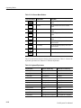
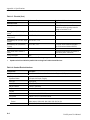
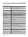
Table 1–3: Power for Modules (with Probes)
1–10
Module
Power (watts)
92A16
107
92A16E
83
92A96/SD/UD
1401
92A96D/XD
140
DAS System User Manual
Getting Started
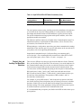
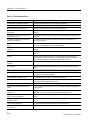
Table 1–3: Power for Modules (with Probes) (Cont.)
Module
Power (watts)
92C96D/XD/SD
1401
92A60
130
92A90/D
130
92S16
78
92S32
79
92SX109
78
92SX118
79
92C02
30
92HS8
20
92HS8E
12
1
92C96 Acquisition Module power requirements
reduced to 140 W max. effective SN B061162 and
above.
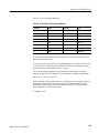
The system software checks for certain configurations at power-on, and also
prompts you to use the correct power supply and power cord. The power supply
and module cards can be damaged if you have an illegal configuration, the wrong
power supply, or the wrong power cord. For example, if you have more than four
92C96 Modules in one mainframe, the system will display a warning message at
power-on and then shut down.
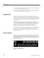
Site Considerations
Information provided here describes the environment in which the mainframe,
terminal, and modules should be operated; the intended site must meet the stated
conditions.
Mainframe Site Considerations. The mainframe will operate in a temperature
environment between +10° C and +40° C (+50° F and +104° F). The maximum
heat dissipation is 3,750 BTUs per hour.
When the mainframe is to be operated on a bench or cart, it should be placed in a
normal, upright position. For proper cooling, allow at least four inches (10.2 cm)
of clearance in front of and behind the mainframe; allow at least two inches
(5.1 cm) of clearance on both sides of the mainframe.
If the need arises, the mainframe can also be operated while on its right side
(media drives down). If positioned on its side, the mainframe must be raised off
the working surface a minimum of two inches (5.1 cm). This permits proper air
flow for cooling purposes.
DAS System User Manual
1–11
Getting Started
CAUTION. Overheating can occur if the mainframe is operated without the cover
or when positioned on its side without being raised off the work surface. Place
two equal height lifts at the front and back of the mainframe. The lifts must not
cover or block the air vents at the front (side) of the top cover, the front, or rear
of the mainframe.
The Master mainframe can support the weight of one Expansion mainframe
placed on top, or one Expansion mainframe and one 92HS8 cabinet, or two
92HS8 cabinets. When the Master mainframe is to be connected to more than
one Expansion mainframe, all mainframes must be mounted in a rack. The rack
must provide sufficient air flow to keep the mainframes’ maximum operating
temperature from exceeding +40° C (104° F). Complete instructions for
installing rackmount hardware are included in the Option 05: Rackmount
Installation Instructions.
Terminal Site Considerations. The color terminal is intended for use in normal or
semi-harsh environments. The terminal will operate in a temperature environment between +10° C and +40° C (+50° F and +104° F). The maximum heat
dissipation is 613 BTUs per hour.
Terminal Connections
The terminal connections differ depending on whether your DAS will be used in
a networked or stand-alone operation.
Networked Operation. For networked operation (DAS/NT), a console RS-232
terminal is required for selected operations such as displaying error or status
messages, setting network parameters using the Configuration utility, or installing
software. The terminal connects to the Terminal port on the mainframe. Any
RS-232 terminal with VT100 or ANSI compatibility or terminal emulation is
acceptable. The terminal should be capable of displaying 24 lines of 80 characters.
The terminal baud rate should be set to 38400. You should change the terminal
baud rate to match that of the mainframe. If necessary, you can change the baud
rate of the mainframe (refer to Terminal, Host, and Auxiliary Port Baud Rate
Selections on page 1–17). For information on the mainframe RS-232 pin-outs,
refer to Host Computer or Serial Printer Connections on page 1–16.
For more information on installing the networked operation, refer to the
92XTerm User Manual.
Stand-Alone Operation. For stand-alone operation (DAS/XP), the X terminal
connects to the logic analyzer mainframe with an RS-232 serial cable (provided
as a standard accessory) and a Thinnet cable.
Refer to the terminal installation manual that came with your terminal while
performing the following steps:
1–12
DAS System User Manual
Getting Started
1. Connect the RS-232 serial cable from Terminal Port 0 to the Terminal port
on the rear panel of the mainframe.
2. Connect a BNC-T connector to the Thin Ethernet BNC connector on the logic
module of the terminal. Connect a second BNC-T connector to the BNC
connector on the back of the mainframe.
3. Connect a 50 Ω terminator to one side of the BNC-T connector on the logic
module and another terminator to the BNC–T connector on the mainframe.
4. Connect the 50 Ω BNC cable from the unused side of the BNC-T connector on
the logic module to the unused side of the BNC-T connector on the mainframe.
5. Connect the keyboard and the mouse to the logic module.
6. Connect the monitor cable from the monitor to the logic module.
7. Connect the power cord (or power supply) to the logic module.
8. Connect the power cord to the monitor power connector.
9. Power on the monitor and logic module. Wait for the serial window to
appear and then power on the mainframe.
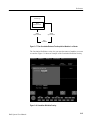
The terminal should be set for the correct settings to communicate with the
mainframe when it is shipped from the factory. After powering on the terminal
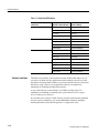
and the mainframe, the terminal will display its Boot Monitor. Table 1–4 lists the
default boot parameters of the terminal. If the terminal does not boot properly,
you should check the boot parameters against those in the table.
Table 1–4: Terminal Default Boot Parameters
Parameter
Default Value
Parameter
Default Value
IADDR
10.0.0.2
DNODE
0.0
IHOST
10.0.0.1
BMETHOD
ROM
IMASK
255.0.0.0
BDISPLAY
DISABLED
IGATE
0.0.0.0
BAFROM
NVRAM
BPATH1
os
1
On initial power on, the default value is /XP300/os (/XP10/os for the 9202XT and
9203XT Terminals) and then changes to os.
The terminal should display a series of messages in the Boot Monitor. When the
boot process is complete, the serial window will be displayed with the word
“Connected.” The serial window should then display the file system check
messages as the system completes its boot process. After a few moments, the
DAS display appears.
DAS System User Manual
1–13
Getting Started
Mainframe Connections
After determining the location of your mainframe, you are ready to connect the
mainframe to the power source, to the X Terminal, or to a host computer network.
Expansion Mainframe Connections. When you add one Expansion mainframe to
your system, you can place it on top of the Master mainframe. If you connect
multiple mainframes, place them in a rackmount configuration using the instructions
provided in the Option 05: Rackmount Installation Instructions. A set of sticky-back
labels, supplied with each Expansion mainframe, should be affixed to the rear panel
of each Expansion mainframe to identify slot numbers. You can use blank labels to
cover the Terminal, Host, and Auxiliary lettering printed on the rear panel.
The procedure for connecting one Expansion mainframe is basically the same as
for three Expansion mainframes. Refer to Power Requirements on page 1–8 for
details on power cord/supply requirements.
When fully connected, the Master mainframe controls the power-on sequence of
the attached Expansion mainframes. If, for example, a diagnostic test at
power-on encounters a serious problem in a mainframe in the chain, the
diagnostics do not allow any mainframe to power up.
Refer to Figure 1–3 while performing the connection procedure. You will need
both a #1 and a #2 Phillips screwdriver to perform the connection.
To Ground Lug on DAS 92E9
Master Mainframe
Retaining Bracket
To Expansion Slave
Board in DAS 92E9
Expansion Cable
Board Housing
Ground Lug
Figure 1–3: Master and Expansion Mainframe Connections
1–14
DAS System User Manual
Getting Started
1. Ensure the 92C02 Module is correctly installed in slot 8 of the Master
mainframe and all Expansion mainframes. (Note: The last Expansion
mainframe in the chain does not require a 92C02 Module installed in slot 8.)
2. Install the L-shaped retaining bracket on the rear panel of the mainframe using
the two screws provided. Attach the bracket over the hole for slot 8, rows C
and D. Use the screw holes provided for the probe retaining brackets.
3. Using care not to bend pins, plug the end of the expansion cable board
housing into the 92C02 connector at slot 8. Attach the housing to the
retaining bracket with the two screws provided.
4. Connect the ground cable by removing a screw on the mainframe and placing
the ground lug under the screw head (see Figure 1–3). Tighten the screw using
care not to strip the screw threads. Connect the other end of the ground cable to
the ground lug of the next Expansion mainframe in the chain.
Probe Connections. The probes for the acquisition and pattern generation modules
attach to the cards through openings in the rear panel of the mainframe(s) except for
the 92HS8. For information regarding proper use and connection of your probe,
refer to the user manual for the module using that probe.
GPIB Port Connections. If you have a 92C02 GPIB/Expansion Module installed
in the Master Mainframe with the GPIB port connector, you can connect the
GPIB cable to the port connector. However, if you do not plan to use the GPIB
feature on the 92C02 Module, you can leave the GPIB cable either connected or
disconnected without affecting the other functions of the module.
Use the following steps to connect the GPIB cable to the Master mainframe:
1. Press the GPIB cable male connector onto the port connector.
2. Hand-tighten the two screws on both sides of the GPIB connector to hold it
in place.
3. Connect the other end of the GPIB cable to your host computer in a
similar manner.
Mainframe Grounding. To reduce susceptibility to line spike or line variations, it is
recommended that you connect a ground lead from the ground lug on the rear of the
mainframe to ground; a short lead made from braided strands is recommended.
DAS System User Manual
1–15
Getting Started
Host Computer or Serial
Printer Connections
You can connect the DAS to a host computer or to a serial printer with a serial
cable. Connect the serial cable to either the Host or Auxiliary 9-pin DCE ports on
the rear of the mainframe. If the host computer has a 9-pin DTE male connector,
connect straight through using a 9-wire cable with a 9-pin female connector on one
end and a 9-pin male connector on the other end. If your host computer or serial
printer has a 25-pin male connector, use an 8-wire cable with connectors wired as
shown in Table 1–5.
Table 1–5: 9-pin DCE-to-25-Pin DTE Cable Connections
Port Signal Name
9-Pin Male Connector
(mainframe End)
Terminal Connector
Protective Ground (Shield)
(Shield)
(Shield)
Carrier Detect
Pin 1
Pin 1
Receive Data
Pin 2
Pin 2
Transmit Data
Pin 3
Pin 3
Data Terminal Ready
Pin 4
Pin 4
Signal Ground
Pin 5
Pin 5
Data Set Ready
Pin 61
No Connection
Request To Send
Pin 7
Pin 7
Clear To Send
Pin 8
Pin 8
1
Pin 6 is pulled up to +5 V.
If your host computer or printer has a 25-pin DCE female connector, you must
provide a cable wired as shown in Table 1–6.
Table 1–6: 9-pin DCE-to-25-Pin DCE Cable Connections
1–16
Port Signal Name
9-Pin Male Connector
(mainframe End)
25-Pin Male Connector
Protective Ground (Shield)
(Shield)
Pin 1
Carrier Detect
Pin 1
Pin 4
Receive Data
Pin 2
Pin 2
Transmit Data
Pin 3
Pin 3
Data Terminal Ready
Pin 4
Pin 5
Signal Ground
Pin 5
Pin 7
Data Set Ready
Pin 61
Pin 6
Request To Send
Pin 7
Pin 8
DAS System User Manual
Getting Started
Table 1–6: 9-pin DCE-to-25-Pin DCE Cable Connections (Cont.)
Port Signal Name
9-Pin Male Connector
(mainframe End)
25-Pin Male Connector
Clear To Send
Pin 8
Pin 20
1
Pin 6 is pulled up to +5 V.
The serial printer connects to the Auxiliary port on the mainframe; the connector
is accessible on the rear panel. When printing to a serial printer the Auxiliary
Port output data format consists of 8-bits/character, no parity and one stop bit.
For specific information on using a printer with specific modules, refer to the
appropriate module user manual.
The baud rate and flow control are selectable in the Communications menu. For
information on how to set the Baud rate DIP switches, refer to Terminal, Host,
and Auxiliary Port Baud Rate Selections.
When printing to a serial printer, ensure that your printer communication settings
match those of the Auxiliary port. For specific instructions on the use and care of
your printer, refer to its supporting documentation.
Output data is transmitted on pin 2 of the Auxiliary port connector and is
received on pin 3. For recommended cable connections to either DTE or DCE
type serial printer ports, refer to Tables 1–5 and 1–6 on page 1–16.
Terminal, Host, and
Auxiliary Port Baud Rate
Selections
There are two different ways that you can select the baud rates for the Terminal,
Host, and Auxiliary Ports on the DAS. The easiest way is to set the baud rates in
the Communications menu. You can also override the selections in the Communications menu using the DIP switches mounted on the Controller board. You
can access these switches through an opening on the rear panel of the mainframe.
DIP switch pairs 3 and 4, 5 and 6, and 7 and 8 select the baud rates for the
RS-232 ports as listed in Table 1–7. DIP switch 1 is the left-most switch as you
face the rear of the mainframe. The operation of DIP switches 1 and 2 is
described later in this manual.
For example, if you set DIP switches 7 and 8 both in the up position, the baud
rate for the Auxiliary Port (serial printer port) will always power on to a default
baud rate of 9600. You can use the other switch settings to provide alternative
baud rate settings. The restore parameters setting causes the three ports to power
on with the baud rates specified in the Communications menu.
It is recommended that you operate your DAS with all DIP switches in the up (or
open) position.
DAS System User Manual
1–17
Getting Started
Table 1–7: Baud Rate DIP Switches
Switch Use
Setting
(Up=Open, Down=Closed)
Result of Setting
Boot Control (Switches 1 & 2)
Up / Up
Normal system boot
Down / Up
BOOT?> prompt
Up / Down
Not used
Down / Down
Not used
Up / Up
38400 baud (default)
Up / Down
2400 baud
Down / Up
1200 baud
Down / Down
Restore Parameters
Up / Up
9600 baud (default)
Up / Down
2400 baud
Down / Up
1200 baud
Down / Down
Restore Parameters
Up / Up
9600 baud (default)
Up / Down
2400 baud
Down / Up
1200 baud
Down / Down
Restore Parameters
Terminal Port (Switches 3 & 4)
Host Port (Switches 5 & 6)
Auxiliary Port (Switches 7 & 8)
Software Installation
The DAS comes with the system software already installed and ready to use. If
you order your DAS with any application software products (such as one of the
microprocessor disassembler products), you must install the software on the hard
disk before using it. Refer to your application software user manual for
information on installing the application software.
A copy of the back-up system software is available on floppy disks. For
information on installing or reinstalling the system software, refer to Appendix D: Loading System Software.
If you connect your system to a LAN network, you must set the network parameters
for your system as assigned by your system administrator. Details on setting the
network parameters are provided in Appendix E: Configuration Utility.
1–18
DAS System User Manual
Getting Started
Configuration
You can configure the DAS with acquisition and pattern generation modules to
address various needs. DAS modules consist of printed circuit cards that must be
installed in a mainframe. A card cage within the mainframe holds all DAS modules.
Hardware
The modules are the building blocks of the DAS. These modules are installed in
the mainframe according to configuration guidelines given in the user manual
that accompanies each module; a summary of the guidelines are also included
later in Appendix F: User Service. See Table 1–8 for a list of available modules.
Table 1–8: Acquisition and Pattern Generation Modules
Module
Purpose
Channels
Memory Depth
Speed
92A16
acquisition
16
4K
200 MHz
92A16E
acquisition expander
16
4K
200 MHz
92A602
acquisition
60
32 K
20 MHz
92A60D1
acquisition
60
128 K
20 MHz
92A901
acquisition
90
32 K
20 MHz
92A90D1
acquisition
90
128 K
20 MHz
92A96, 92C962
acquisition
96
8K
100 MHz
92A96D, 92C96D2
acquisition
96
32 K
100 MHz
92A96XD, 92C96XD2
acquisition
96
128 K
100 MHz
92A96SD, 92C96SD2
acquisition
96
512 K
100 MHz
92A96UD2
acquisition
96
2M
100 MHz
92HS83
acquisition
8
8K
2 GHz
92HS8E3
acquisition expander
8
8K
2 GHz
92S16
pattern generation
16
1K
50 MHz
92S32
pattern generation
32
8K
50 MHz
92SX109
pattern generation
9
2K
100 MHz
92SX118
pattern generation
18
16 K
100 MHz
1
The 92A60/D and 92A90/D are both two-card sets; other modules are single-card sets.
2
The 92A96 High-Speed timing offers asynchronous support of 48 channels at 200 MHz and 24 channels at 400 MHz.
3
The 92HS8 has a mainframe cabinet that connects to the DAS through an interface card.
DAS System User Manual
1–19
Getting Started
92A16/E Data Acquisition Modules. The 92A16/E Module is a 200 MHz,
16-channel data acquisition module suited for general-purpose, medium-speed
hardware timing analysis and for high-speed state analysis. It uses two P6461/E
probes (or lower-bandwidth P6460 probes) to acquire data with either an internal
(asynchronous) or external (synchronous) clock equation. Data is stored on each
active clock edge until a trigger is generated and the delay counter value is
reached. Support for two-phase clocking (demultiplexing) is also provided.
The 92A16 Module acts as either a Master or an Expansion module; the 92A16E
Module is strictly an Expansion module. The 92A16 and 92A16E Modules can
be combined into a single 96-channel-wide module in one mainframe; all
channels operate under the same trigger and clock conditions and run at
200 MHz (no speed vs. channel width trade-offs). The first 64 channels can be
used for word recognition. In addition to stand-alone operation, the 92A16
Module can be correlated with other data acquisition modules in the DAS
mainframe to provide multiple time base capabilities.
92A60/D and 92A90/D Data Acquisition Modules. The large number of acquisition
channels (60 maximum) allows the 92A60 Module to serve as the basis for a
variety of DAS features, including microprocessor support, general-purpose state
analysis, and software performance analysis. The 92A90 Module (90 channels
maximum) provides increased width.
The 92A60 and 92A90 Modules are available in two versions: the standard
92A60/90 Module versions provide 32 k memory depth; the 92A60D/90D
Module versions offer 128 k memory depth.
Both the 92A60 and 92A90 Modules use a retargetable buffer probe that can be
quickly changed to fit the application. The 92A60/90 Modules cannot be
combined for applications requiring more channels; however, acquired data can
be time correlated with other acquisition modules.
92A96 and 92C96 Data Acquisition Modules. The 92A96 Module is a 100 MHz,
100-channel data acquisition module suited for general-purpose, medium-speed
hardware analysis, 32-bit microprocessor support, and up to 400 MHz highspeed timing analysis. The 92A96 Module can be expanded to provide up to 288
channels of acquisition at speeds of 100 MHz (synchronous) and 72 channels at
speeds of up to 400 MHz (asynchronous). The module comes with 8-channel
probes and single-channel clock probes.
The 92C96 Module is a subset of the 92A96 Module that can easily be upgraded
for deeper acquisition memory. Unless stated otherwise, the terms 92C96 and
92A96 are used interchangeably.
1–20
DAS System User Manual
Getting Started
The 92A96 Module is currently available in the following versions:
H
The 92A96D Module with a 32 K memory depth
H
The 92A96XD with a 128 K memory depth
H
The 92A96SD with a 512 K memory depth
H
The 92A96UD with a 2 M memory depth
In addition to stand-alone operation the 92A96 Module can be time-correlated
with the 92A16, 92A60/90, or other 92A96 Modules to provide multiple time
base capabilities.
92HS8/E High-Speed Acquisition Modules. The 92HS8 Module allows designers of
high-speed digital systems (clocks of 100 MHz and faster) to use digital analysis
techniques to locate timing problems where signal differences are as little as
1 ns. Eight channels (each with glitch detection) can acquire data using an
internal clock. Both data and glitch information can be stored and can also be
used as a trigger source. The internal time base provides sampling intervals from
5 ms to 500 ps; memory depth is 8k words per channel. A specialized form of
external clocking (synchronous acquisition) called External Asynchronous
clocking is available.
The 92HS8 Module channels can be expanded to a maximum of 32 channels by
adding a 92HS8E cabinet and two 92HS8C cabinets.
92S16/32 Pattern Generation Modules. These modules provide pattern generation
capabilities that can be used as a stand-alone stimulation source or can be linked
with data acquisition to provide a test system for debugging and verifying
components, boards, and systems. The 92S16 Module (16 channels plus two
strobe/data channels) features algorithmic pattern generation with a 1 K memory
depth; the 92S32 Module (32 channels plus 4 strobe/data channels) features
stored pattern generation with an 8 K memory depth. These modules can be used
separately or together to create the type of output pattern control that suits your
application. A single 92S16 Module can control up to seven 92S32 Modules;
without a 92S16 Module, up to eight 92S32 Modules can operate together.
Both modules provide pattern generation with the ability to vary the placement
of each edge in increments of 1 ns. The P6463A Pattern Generation probes
deliver the output pattern to the probe tip, providing drive equivalent to TTL or
CMOS series components. The P6464 Pattern Generation probes deliver the
output pattern to the probe tip, providing drive equivalent to AS (TTL) and
10 KH (ECL) series components.
DAS System User Manual
1–21
Getting Started
92SX109/118 Pattern Generator Modules. These modules also provide high-speed
100 MHz pattern generation. The 92SX109 Module is based on an enhanced
92S16 Pattern Generator Module. It is a 9-channel stimulus system that features
algorithmic pattern generation. This system can operate to a maximum of
100 MHz across nine channels. Total memory is 2 K for each channel for vector
patterns and 1 K for instructions.
The 92SX118 Module is based on an enhanced 92S32 Pattern Generator module.
It is an 18-channel, sequential stimulus system. This option can operate to a
maximum of 100 MHz. The total memory is 16 K for each channel.
NOTE. For more detailed information on individual modules, including
specifications and complete menu/field descriptions, refer to the appropriate
user manual.
System Software
The DAS is controlled by system software which is stored on the hard disk drive.
To determine the version number of the software currently installed in the mainframe, check the Diagnostics menu. The Version menu displays the version numbers
of modules in the mainframe; both menus are in the Utility menu group.
System software loads into memory (RAM) at power on and performs the
following tasks:
H
Manages system resources (that is, memory, CPU, storage devices, common
control functions, files and file access, and data communication I/O devices)
H
Provides system service subroutines so that acquisition and pattern generation modules and applications programs have a common set of subroutines
H
Provides common system control functions such as start/stop control and
allocation of system hardware resources
H
Controls communication between standard subroutines, modules, application
software, and I/O devices (standard, optional, and mass storage)
As a backup, the DAS can also load system software from a set of floppy disks.
1–22
DAS System User Manual
Getting Started
Application Software
Application software packages are available; each package includes an instruction manual. Refer to the appropriate manual for more detailed information. A
list of application software currently installed is shown in the Version menu. Use
the Disk Services menu to install application software from floppy disks.
The Microprocessor Support packages provide both hardware and software
mnemonic disassembly formats. Each support package includes a microprocessor-specific probe adapter which provides the hardware necessary to properly
acquire data from the microprocessor.
First Time Operation
After connecting the terminal and the probes, you should be ready to power on
the instrument.
Power on the terminal and then the mainframe. The terminal performs its
power-on checks; then the power-on sequence for the system begins. The DAS
temporarily displays a power-on screen with the product logo, system software
version, and information on the hard and floppy disk drives.
When the power-on sequence is complete, the system displays the Menu
Selection overlay. You are now ready to use the DAS.
Performing an Acquisition
Acquire data by using the following basic steps:
1. Connect the probes from the DAS to the system-under-test. If necessary,
refer to your acquisition module user manual for details on connecting
probes.
2. Set up the acquisition parameters by either programming the Setup menus or
by restoring a setup from the hard disk drive.
3. Acquire data (normally you can press the F1: START function key).
4. Use the Display menus to analyze the results of the acquired data.
These are the basic steps for acquiring data. You should refer to the acquisition
module user manual for more details on setting up and using the menus.
Moving Forward
The Digital Analysis System is a powerful tool for solving complex problems. It
can be as simple as pressing the start button. For more complex applications, you
can restore or load setups from application software programs and analyze the
resultant data on a host computer network.
The following tools or products can be used with the Digital Analysis System to
help you solve hardware or software problems.
DAS System User Manual
1–23
Getting Started
Microprocessor Disassemblers. The DAS can be used with several microprocessor disassembler application software packages. Each application comes with
software and an instruction manual.
Networked X-Windows Interface. The networked X windows interface is standard
with DAS/NT systems. The 92XTerm product allows you to upgrade a standalone DAS system to a DAS/NT system with a network X-window interface.
You can display the menus on a workstation while the actual mainframe is
located in a remote location. The 92XTerm upgrade comes with software and
user manual.
Programmatic Command Language (PCL). The 92LANP product allows you to
control the operation of the DAS from a host computer over a LAN (local area
network) using the Programmatic Command Language. The 92LANP product
comes with manuals and software.
You can also use PCL with your DAS over the General Purpose Interface Bus
(GPIB) if you have an optional 92C02 GPIB/Expansion Module installed in your
mainframe. You can use several different GPIB communications software
packages. For detailed information on the Programmatic Command Language,
refer to the DAS 9200 Programmatic Command Language User Manual.
Although PCL comes standard with the instrument and can be used with RS-232, it
is recommended that you use PCL with the 92LANP product or over GPIB.
Discrete I/O Port. The 92PORT product allows you to monitor and send signals to
a system-under-test using the 37-pin D-connector on the rear of the mainframe.
1–24
DAS System User Manual
Functional Overview
This chapter provides brief introductory information on the Digital Analysis
System. It provides a brief description of the product, an overview of its menus,
and includes a tutorial for first time users.
The Digital Analysis System uses a common mainframe for the DAS/NT and
DAS/XP systems; the main difference is that the DAS/NT system is the
networked version of the DAS/XP system. The DAS/NT system comes standard
with network software, while the DAS/XP system is available as a stand-alone
system with a color terminal. You can tell the difference between the two
systems by the stickers on the front panel of the mainframes.
Figure 2–1 shows a front view of the Master mainframe. The DC ON/OFF
switch, floppy disk drive, and hard disk drive are located at the front of the
instrument as shown. Expansion mainframes look similar to the Master
mainframes, but do not include the power switch and disk drives.
The DC ON/OFF switch is located in the upper-right corner of the front facade
of the Master mainframe. When in the OFF (Standby) position, the DC voltages
are removed from the circuitry; however, AC voltages still exist inside the
mainframe. The switch is illuminated when it is in the ON position. To remove
AC voltages from the mainframe, you must remove the power cord.
The DC ON/OFF switch, not the power cord, should be used for powering the
mainframe(s) on and off. Since the power-off sequence is logic-controlled, you
will notice a slight delay before DC power is removed from the mainframe.
During a normal power off, the mainframe saves information on the type of
shutdown occurring and saves the current state of the file system.
DAS System User Manual
2–1
Operating Basics
Front Panel
DC On/Off
switch
Floppy Disk
Drive
Hard Disk
LED
Figure 2–1: Front View of the DAS Mainframe
Figure 2–2 shows a rear view of the Master mainframe. Acquisition probes and
pattern generation probes connect to the individual modules at the rear of the
instrument. Expansion mainframes (not shown) do not include the rear panel
connectors (RS-232 ports, Ethernet ports, and I/O port).
The Line Voltage Indicator on the rear panel (Figure 2–2) shows the correct
nominal voltage for the power source you are using, either 115 V or 230 V. If the
mainframe has the three-phase power supply/cord installed, there is no Line
Voltage Indicator on the rear panel. The line voltage indicator is only an indicator
of the line voltage selection strapping within the power supply. If the indicator
shows the wrong voltage for the power source being used, refer a qualified
service person to the DAS 9200 Technician’s Reference Manual for power supply
reconfiguration and replacement of the power cord and fuse.
2–2
DAS System User Manual
Operating Basics
GPIB Connector
Fuse
92LANSE
Connectors
Power Cord
Connection
Line Voltage
Indicator
Discrete I/O Connector
RS-232 Port Connectors
Figure 2–2: Rear View of the DAS Master Mainframe
Powering On and Powering Off
The power on and power off procedures differ depending on whether you have a
DAS/NT or a DAS/XP system. Because the DAS/NT is connected to a network,
you should not power off the mainframe; operation is controlled from a
workstation (refer to the 92XTerm User Manual for information on controlling
the mainframe from a workstation).
Powering On the DAS/XP
To normally power on the DAS/XP system, power on the terminal and then the
mainframe. The terminal goes through its power-on tests before the mainframe
performs its system checks. When all power-on checks have been completed, the
Menu Selection Overlay displays. Figure 2–3 shows an example of the Menu
Selection overlay.
Powering On the DAS/NT
If you have a DAS/NT system, the Menu Selection overlay displays after you
start the 92XTerm application. From then on, all menus are similar to those in a
DAS/XP system.
DAS System User Manual
2–3
Operating Basics
Figure 2–3: Menu Selection Overlay
Workspace Menu
If your DAS is connected to a network and configured with the 92XTerm
software (DAS/NT) and you have a Tektronix X terminal display (such as a
9206XT), you can use the Workspace menu of the X terminal to add functions to
your DAS. Figure 2–4 shows an example of the Workspace menu.
You can restart the windows by selecting TekLA ➞ Open Window. When you
start the DAS in this manner, you can specify the font size of the DAS window
using one of the selections in the pull-down menu. If you select Auto fontsize,
the DAS window will be automatically sized to your terminal.
You can close the menus (or shut down a remote window session) by selecting
TekLA ➞ Close Window, effectively resetting the DAS making it available for
other local or remote users.
You can also start other applications or tools if they are available. For example, if
you have the 92Port application, you can start it from the Workspace menu (refer
to the 92Port Instructions for information on the 92Port application). The Print
Screen tool lets you capture menus and save them in a file or send them to a
printer (refer to Capturing and Printing Menus on page 3–72 for instructions on
using the Print Screen tool).
2–4
DAS System User Manual
Operating Basics
Workspace
Local Clients
Tek LA
92 port
Print Screen
Refresh
Restart WM
Reread Menu File
Open Window
Auto fontsize
Close Window
font - 12
font - 16
font - 20
font - 24
Exit WM
Exit
Figure 2–4: Workspace Menu (on Tektronix X Terminals)
Powering Off
To power off a non-networked DAS, simply turn off the DC ON/OFF switch on
the mainframe and then power off the terminal. On a DAS/NT (92XTerm)
system, you can quit the application by clicking on the title bar and selecting quit
from the pull-down menu on the workstation.
Menu Overview
The Digital Analysis System is controlled by interactive menus that appear on
the terminal screen. A menu is a screen display that offers selectable or scrollable
choices. Some menus are associated with overlays (submenus) that provide
additional menu selections or information.
The menu set can be divided into four separate groups:
Setup Menus
H
Setup menus
H
Display menus
H
Utility menus
H
Application menus
Setup menus define the conditions under which modules will operate and
communicate with other modules.
There are two classes of Setup menus: those that control system-wide operating
parameters and those that pertain specifically to one module type.
DAS System User Manual
2–5
Operating Basics
System Setup Menus. These menus will always appear on the Menu Selection
overlay (Cluster Setup can only be entered after you have defined a cluster using the
System Config menu). The System Configuration, Cluster Setup, and System
Monitor menus are described in more detail in the Reference section of this manual.
The following System Setup menus are available:
H
The System Configuration menu. This menu lists the modules installed in the
instrument. At initial power-on, the default groupings of modules are displayed;
you can select different module formations (groups of modules of the same
type). A typical example of when you might want to change a module
formation is when your application requires more channels in a module than are
currently defined. For example, by selecting different groupings of 92C96 cards
in a module, you can add needed acquisition channels.
The System Configuration menu also displays the current collection of modules
in a cluster; you can change the clusters with the Cluster Definition overlay.
H
The System Monitor menu. This menu displays the status of the modules
installed in the system as well as the clusters. It lets you see at a glance
which modules and clusters are running, which are waiting for their trigger
condition, which have acquired data and stopped, and which are autorunning.
If you acquire data for the selected module or cluster using Autorun, the
number of times that module or cluster has been started is shown in the
upper-right corner of the status line.
The System Monitor menu is especially valuable when you have defined
several different clusters and have them running simultaneously.
H
The Cluster Setup menu. This menu is only selectable after you create a
cluster using the Sys Configuration menu. It lets you define how modules
assigned to the same cluster interact. Specifically, it allows you to define
signals passed between modules, time-correlate data acquired by two
different modules, and specify Autorun conditions where a module acquires
data, compares it to a reference memory file, and based upon the comparison, stops or automatically repeats the acquisition.
Module Setup Menus. Module Setup menus that appear below the System Setup
menus correspond specifically to the module currently selected. For example, if
92C96-1 is the active module, the Config, Channel, Clock, Trigger, and Monitor
menus pertain only to this one module; other Setup menus will appear when you
select a different module (for example, 92S16-1 or 92S32-1). Refer to your
module user manual for complete details on all the menus, overlays, and fields of
the Module Setup menus.
Figure 2–5 shows the Setup menus for each module.
2–6
DAS System User Manual
Operating Basics
MODULE
SETUP
92A16/16E
92A60/90
92A96
92C96
System Configuration
Cluster Setup*
System Monitor
Configuration
Clock
Channel
Trigger
Monitor
92HS8/8E
System Configuration
Cluster Setup*
System Monitor
Configuration
Channel
Trigger
92S16/32
System Configuration
Cluster Setup*
System Monitor
Configuration
Channel
Program
Monitor
* All modules in a cluster share a Cluster Setup menu.
Modules not in a cluster have no Cluster Setup menu.
Figure 2–5: Setup Menus for Each Module
The following Setup menus are available for the acquisition module:
DAS System User Manual
H
Configuration Menu. The Config menu allows you to select the software
support mode, default memory size, and whether or not you want to capture
signal glitches. This menu shows you the name and type of module you
have, including the number of acquisition channels available, and it indicates
the number of intermodule signals you have defined.
H
Channel Menu. The Channel menu allows you to create channel groups and
define their names, radix, and order. You can also assign the individual
channel names and define their polarities and threshold voltages.
H
Clock Menu. The Clock menu lets you select the sample clock source and
the internal clock period or the external clock equations and qualifiers. You
can choose microprocessor-specific options if you have microprocessor
support application software installed on the hard disk and selected in the
Config menu.
2–7
Operating Basics
H
Trigger Menu. The Trigger menu lets you define the trigger position, trigger
specification program—including states, events, and actions. You can also
define the type of storage qualification you want. You can use trigger
libraries that contain templates for trigger specification programs or create
your own libraries.
H
Monitor Menu. The Monitor Menu monitors the progress of the acquisition.
It displays if an acquisition is not completed within a few seconds. You can
use the Monitor menu to debug trigger specification programs by monitoring
the status of the acquisition, the counter or timer values, and the amount of
acquisition memory being used.
The following Setup menus are available for the pattern generation modules:
Display Menus
2–8
H
Configuration Menu. The Configuration menu shows the current hardware
configuration and software mode for the pattern generation module.
H
Channel Menu. The Channel menu lets you collect channels into logical
groups for data entry and display purposes. You can change the names, radix,
and display order of each group.
H
Program Menu. The Program menu allows you to enter data and instructions
to stimulate the circuit or system under test. You can also send a signal to the
acquisition module.
H
Monitor Menu. The Monitor menu lets you debug pattern generation
programs by watching pattern-generator/circuit under test interactions at a
reduced clock rate. You can set break points in the pattern generation
programs and single-step through problem areas.
Display menus control the display format and viewing characteristics of acquired
data. Display menus are module-dependent (see Figure 2–6). Module display
menus are described in detail in the module manuals; Application menus are
described in the application software manuals.
DAS System User Manual
Operating Basics
MODULE
Display
92A16/16E
State
Timing
Graph
Disassembly
92A96
92C96
92A60/90
State
Timing
Graph
Disassembly
Stack
Data
92HS8/8E
State
Timing
Graph
9216/32
(no Display Menus
with these Modules)
Figure 2–6: Module Display Menus
The following Display menus are available for the acquisition module (there are
no display menus for the pattern generation modules):
DAS System User Manual
H
State Menu. The State menu displays acquired data as a table of logical
states of the input channels. Channels are organized as defined in the
Channel menu and data is displayed in the radix you select.
H
Timing Menu. The Timing menu provides a graphic display with each input
channel represented as a digital (two-state) waveform. It also shows the bus
value of all channel groups defined in the channel menu.
H
Graph Menu. The Graph menu displays a graph of data from any two of
the selected channel groups plotted against their locations in the
acquisition memory.
H
Disassembly Menu. The Disassembly menu is a table display that translates the
logic input for specific channel groups into microprocessor-specific mnemonics.
2–9
Operating Basics
Utility Menus
Utility menus provide system-level tools. They allow you to control data
transfers to and from the hard and floppy disks, and they allow you to define the
parameters that control the communication ports.
The following Utility menus are available:
Application Menus
2–10
H
Save/Restore Menu. This menu allows you to save instrument setups and
acquisition memory data, restore instrument setups from previously saved files,
and delete instrument setup and reference memory files from the hard disk.
H
Disk Services Menu. This set of menus provides the tools necessary to
duplicate the contents of a floppy disk, format and verify floppy disks,
backup and restore user files with floppy disks, and copy and delete specific
files. A directory of all existing file names on floppy or hard disks is
provided; accompanying information specifies the number of kilobytes the
file occupies and the creation or revision date and time of the file.
H
Symbol Editor Menu. This menu allows you to create and edit symbol tables
that you can use to specify trigger word patterns and evaluate acquired data.
You can create and edit either range or pattern type symbol tables.
H
Communications Menu. This menu specifies RS-232 port settings and view
network settings. You can specify baud rates and flow control for each
RS-232 port.
H
Diagnostics Menu. This menu provides a list of major system components, a
diagnostic report indicating operational status at power on, a summary and
brief description of the modules installed in the instrument, the system
software version, date and time, and some general user instructions.
H
Version Menu. This menu displays the version numbers of all installed
modules, the current system software, and all installed application software.
Application menus control the operation of application software packages. Most
software supporting the application packages resides on floppy disks and must be
loaded onto the system hard disk before being used. Microprocessor Support
packages provide mnemonic disassembly formats. All nonresident application
software and corresponding menus are described in separate manuals supporting
each application software package.
DAS System User Manual
Tutorial
This tutorial is intended to familiarize you with the menus, operator controls, and
the display conventions of the Digital Analysis System. This section is intended
for beginning users or for experienced users who want to review individual controls
or display functions. The tutorial begins by explaining the mouse-driven interface
and the use of fields and function keys within the menus. It then briefly explains
how to set up menus to acquire and display data with the acquisition module. It is
recommended that you perform the steps in sequence throughout this tutorial.
While this section describes the use of the Digital Analysis System with basic
menus and fields, it does not contain an exhaustive list of all possible combination of menus, keystrokes, mouse selections, and display contexts.
When you power on the system, an initial menu displays the product logo,
copyright information, and system software version. The menu continues to
display while the system software completes the initialization process. After a
few seconds the Menu Selection overlay appears.
Selecting Menus
The Menu Selection overlay lists all available menus that you need to operate the
system. You can move through the menus using the mouse or keys on the
keyboard. Table 2–1 describes the mouse buttons and their functions on a typical
three-button mouse. The table provides a brief overview of using the mouse;
more details of using the mouse in menus are provided later in this tutorial.
Table 2–1: Three-Button Mouse Description
DAS System User Manual
Button
Name
Description
Left
Select
Selects a field. Move the pointer to the field and press
the left button. Use this button to select on-screen
function keys, move the data cursor in display menus,
and scroll acquired data in display menus.
Center
–
No action.
Right
Open
Opens a field or displays a pop-up menu. When a field is
open, use the left button to change the active value of
the opened field; use the right button to select a new
value and close the pop-up menu.
2–11
Operating Basics
Figure 2–7 shows an example of the Menu Selection overlay. The display from
your system should be similar. Note that the overlay has four different types of
menus in the center of the overlay. All of the menus are briefly described under
Menu Overview, earlier in this manual. The function key legends for each of the
menus appear near the bottom of the overlay.
Figure 2–7: Menu Selection Overlay
There are different ways to access menus. The easiest way is to point the mouse
at the menu selection and press the left button. The active (yellow) cursor
automatically moves to the selection and displays the selected menu.
You can also access the menus in one of the following ways:
2–12
H
Point the mouse at the menu selection and press the right button; the yellow
cursor will move to the selection (but will not display the menu). Press the
left mouse button to display the menu.
H
Move the yellow cursor to the menu that you want and press the Return Key.
The menu highlighted by the yellow cursor will display.
H
Point the mouse at one of the function key legends and press the left button.
The menu highlighted by the white cursor will display.
DAS System User Manual
Operating Basics
H
Press the appropriate function key on the keyboard corresponding to the
function key legend in the window. The menu highlighted by the white
cursor will display.
The following steps show how to move between menus using the mouse:
1. Point the mouse at the Diagnostics menu selection under the Utilities column
and press the left button. The Diagnostics menu will display.
The diagnostics menu provides a brief overview of the system. It shows the
contents of the system unit and the results of the power-on diagnostics. It
also shows the current system software version, type of floppy and hard disk
drives, and the current date and time. You can change the date and time by
calling the Set Date/Time overlay. You will use this overlay to become
familiar with the use of the fields and the mouse.
2. Call the Set Date/Time overlay by pointing the mouse at the F5: SET TIME
function key legend and pressing the left button. You can also press the F5
function key on the keyboard. The Set Date/Time overlay appears over (over
lays) the diagnostics menu; it should look similar to Figure 2–8.
Figure 2–8: Set Date/Time Overlay
DAS System User Manual
2–13
Operating Basics
Fields
Most overlays have areas of information (called fields) that you can modify or
select data. You change or modify operating parameters in fields. There are two
kinds of fields: Select fields and Fill-in fields.
Select Fields
A Select field contains a number of predefined choices from which you can
select. While this type of field may contain several choices, it only displays the
current selection until it is opened. You must open a select field to display all the
choices. There are three basic ways of selecting the contents in a Select field:
H
View the entire list of choices and make a selection. With the mouse pointing
at the field, press the right button to display a list of selections. Point the
mouse at the selection you want and press the right button; the specified
selection is highlighted and the pop-up list closes.
H
Cycle through the entire list of choices one at a time and make a selection.
With the mouse, point at the NEXT or PREV buttons at the bottom of the
window and press the left button to cycle through the list of choices. You can
also use the plus (+) or minus (–) keys on the terminal keypad to cycle
through the list of choices.
H
Type in a string of characters that match one of the selections (the character
string that you enter is not case sensitive). Type in the first few characters of
the string until the selection appears. Press the right mouse button or the
Return key to finalize the selection.
Try each of the three methods by changing the information in the Set Date/Time
overlay as follows:
3. Point the mouse at the field to the right of the word Date: and press the right
button.
A pop-up menu appears on the right side of the window with the current
selection highlighted.
4. Point the mouse at the selection you want. If your selection is outside of the
numbers displayed in the pop-menu, you can scroll to the correct selection.
Note the small arrows near the top or bottom of the pop-up menu. These
arrows show that there are more selections outside of the range of selections
displayed in the pop-up menu. You can scroll through the numbers near the
top of the pop-up menu by pointing the mouse just outside and towards the
top of the pop-up menu and pressing the left mouse button. Alternately, you
can scroll through the numbers near the bottom of the pop-up menu by
pointing the mouse just outside and to the bottom of the pop-up menu and
pressing the left mouse button. You can also scroll through the data by
pointing the mouse at the NEXT and PREV buttons on the bottom of the
window and pressing the left button.
2–14
DAS System User Manual
Operating Basics
5. Confirm your selection by pressing the right mouse button. The pop-up
menu closes and the new value will display in the select field.
6. With the cursor in the Day select field, point the mouse at either the NEXT
or PREV buttons near the bottom of the window. Press the left button to
cycle through the choices in the select field.
7. Point the mouse at the Month field and press the left button to move the
cursor to the field.
You can cycle through the data using the methods described earlier.
However, another way to enter data is to type in characters until the desired
selection appears.
8. Type the letter J. The contents of the field changes to one of the words
beginning with the letter J, for example, January.
9. Type the letter u. The contents of the field changes to one of selections
containing the letters Ju, for example, June.
10. Type the letter l. The field contents change to July. Once the correct selection
appears, press the right mouse button to close the field.
If you type an invalid letter an error message will display.
11. If you have not already done so, enter the current date and time and select
the F8: EXIT & Save function key to exit the overlay. The overlay closes
and the full diagnostic menu displays.
Fill-in Fields
A fill-in field is essentially a box that lets you enter information such as a file
name. To use a fill-in field, move the cursor to the field, type in a value, and
press the Return or Enter key, or move the cursor to another field. Using the
mouse, press the left mouse button to select the field and then type in a value;
then press the right button to accept your value. To blank or clear an entire field,
press the Return or Enter key, or press the right mouse button twice.
There are limitations to some fill-in fields. For example, you cannot end a file
name with the underscore character (_). Some fill-in fields do not allow spaces;
while others only allow certain letters or digits. Also, some fill-in fields do not
allow editing — you must reenter the whole message or name.
You will use a fill-in field later in this tutorial.
Field Color Conventions
DAS System User Manual
Different colors identify the type and status of menu fields. The following
conventions apply to all fields in all menus:
H
White text on blue background indicates a closed field.
H
Black text on yellow background indicates a closed field (cursor present).
2–15
Operating Basics
H
White text on orange background is an open field; you can enter characters
for fill-in field or match-choice selections.
H
Gray text on orange background indicates a select field (matched selection
registered) or a field with nonselectable items.
Exiting Overlays
There are two ways to leave an overlay: you can close the overlay saving
changes you have made or close the overlay discarding any changes. To leave the
overlay and save the changes, point the mouse at the F8: EXIT & SAVE function
key legend and press the left button; alternately, you can press function key F8
on the keyboard.
To leave the overlay without saving any changes, select F1: CANCEL &
ESCAPE, or press function key F1. You will be prompted to confirm your action
so you do not accidentally lose any of your changes. Press the Return key to
confirm your actions; the overlay closes and any changes you made are
discarded. Press the Esc (Escape) key to abort the close operation.
There may be some exceptions on what changes are saved or discarded when you
exit the overlays. If you are unsure of the changes and actions for leaving
specific overlays, refer to the discussion of the specific overlays in the Reference
chapter of this manual.
On-Screen Buttons
Notice the two rows of on-screen buttons at the bottom of the menu. These same
buttons appear at the bottom of every menu. These buttons are activated by
pointing the mouse and pressing the left button. Figure 2–9 shows the on-screen
buttons as they appear at the bottom of each menu. Table 2–2 lists the on-screen
buttons and their functions.
Figure 2–9: On-Screen Buttons
2–16
DAS System User Manual
Operating Basics
Table 2–2: On-Screen Menu Buttons
On-screen Button
Button Name
Description
Joydisk
Use this button to scroll through acquired
data. Point to one of the arrows on the
Joydisk to scroll data in the direction of the
arrow.
NEXT
Select Next
Use this button to cycle through items in a
Select field. Pointing at this button displays
the next item in the list.
PREV
Select Previous
Use this button to cycle through items in a
Select field. Pointing at this button displays
the previous item in the list.
Page Up
Scrolls up one half a window of data.
Page Down
Scrolls down one half a window of data.
Shift Scroll Left/Up
Scrolls to the left one half a window at a time
in Timing or Graph menus and up one half a
window at a time in State or Disassembly
menus.
Scroll Left/Up
Scrolls to the left in Timing or Graph menus
and up in State or Disassembly menus.
Scroll Right/Down
Scrolls to the right in Timing or Graph menus
and down in State or Disassembly menus.
Shift Scroll Right/Down
Scrolls to the right one half a window at a
time in Timing menus and down one half a
window at a time in State or Disassembly
menus.
PRINT
Print
Calls the Print overlay allowing you to print
the data in a Display or Setup menu, to a
printer, or to a file.
NOTES
Notes
Displays on-screen notes.
MENU
Menu
Calls the Menu Selection overlay.
UP
DOWN
Table 2–3 briefly describes the bottom row of on-screen buttons. These buttons
are sometimes called macro buttons. The macro buttons, although visible, do not
operate when an overlay is open (excluding the Menu Selection overlay). You
can use these buttons to quickly move between key menus.
DAS System User Manual
2–17
Operating Basics
Table 2–3: On-Screen Macro Buttons
On-screen Button
Button Name
Description
CONFIG
Configuration
Calls the Configuration menu of the selected
module.
Channel
Calls the Channel menu of the selected
module.
Clock
Calls the Clock menu of the selected
module.
Trigger
Calls the Trigger menu of the selected
module.
STATE
State
Calls the State Display menu of the selected
module.
TIMING
Timing
Calls the Timing Display menu of the
selected module.
DISASM
Disassembly
Calls the Disassembly Display menu of the
selected module.
DISK
Disk
Calls the Disk Services menu.
SAVE
Save
Calls the Save/Restore menu.
CHAN
CLOCK
TRIG
The on-screen buttons also have their keyboard equivalents. Table 2–4 shows the
keyboard equivalents for Tektronix X Terminal keyboards.
Table 2–4: Keyboard Equivalents
2–18
Key Function
Typical X Terminal key
Tektronix X Terminal Key
Cursor Up
R8 (Keypad 8)
Keypad 8
Cursor Right
R12 (Keypad 6)
Keypad 6
Cursor Down
R14 (Keypad 2)
Keypad 2
Cursor Left
R10 (Keypad 4)
Keypad 4
Home
R11 (Keypad 5)
Keypad 5
Page Up
R9 (Keypad 9)
Keypad 9
Page Down
R15 (Keypad 3)
Keypad 3
Select Previous
Keypad -
Keypad -
Select Next
Keypad +
Keypad +
Open & Close
Keypad Enter
Keypad Enter
Scroll Left/Up
Ins (Keypad Ins or Keypad 0)
Ins (Keypad Ins or Keypad 0)
DAS System User Manual
Operating Basics
Table 2–4: Keyboard Equivalents (Cont.)
Key Function
Typical X Terminal key
Tektronix X Terminal Key
Scroll Right/Down
Del (Keypad Del or Keypad .)
Del (Keypad Del or Keypad .)
Call Menu Selection Overlay
Function Key F9
Function Key F9
Print
L6 (Copy)
Not Present
Notes
Help
Not Present
Break
L1 (Stop)
Not Present
Rubout
Shift-Backspace
Shift-Backspace
You may want to experiment moving between menus using the on-screen buttons
to become familiar with their operation. Later in this tutorial, you will learn how
to go through the basic Setup menus and use the on-screen buttons to scroll
through data.
NOTE. You can always return to the Menu Selection overlay by selecting the
MENU button at the bottom of the menu or by pointing the mouse at the Status
bar at the top of the menu and pressing the left mouse button.
Function Keys
You have already seen how to use the basic function keys to enter and leave the
Set Date/Time overlay. You have also learned how to use the function keys with
the mouse and from the keyboard. This section provides more information on
using the function keys.
Function keys F1 through F8 are display dependent. In other words, the purpose
of the function key changes as the display changes. For example, function key
F6 in the Channel menu calls the Channel Definition overlay; however, in the
Trigger menu, function key F6 calls the Trigger library. All active function keys
for the current menu are shown. The numbers on the function key legends
(F1-F8) correspond to the numbered function keys on the keyboard (see
Figure 2–10).
DAS System User Manual
2–19
Operating Basics
F1
F2
F3
F4
F5
F6
F7
F8
Figure 2–10: Function Keys Map to the Function Key Legends
On-Line Notes
Occasionally there are situations when you want to learn information about a
function key or field without having to take the time to look up the information
in the manual. Other times you want to know the purpose of a function key when
the name of the function key legend is not obvious. The on-line notes system is
designed to address these problems.
The on-line notes system provides information in the form of brief, quick-access
notes. Two types of notes are available: Field notes and Key notes. The Notes
text appears on the menu in a small window. You call the notes by selecting the
Notes button at the bottom of the menu or by pressing the Help key on the
keyboard.
Field Notes
A Field note gives you a brief, on-line description of the field (or individual
selection, in the case of an opened select field) where the cursor currently
resides. A note is available for each menu field and selection, but only displays
when you select the Notes button. The note disappears when you press the
Esc key or press the left mouse button while pointing inside the thin message
window (displayed directly above the function key legends). If you press any
other key (except function keys), the note disappears and the key works as usual.
Key Notes
A Key note describes what happens when you press any currently active function
key. If a function key legend does not give you enough information, a Key note
is available to provide more detail. A Key note appears when you select the
Notes button and then select a function key; the note disappears when you press
the Esc key. If you press the function key a second time, its function will be
activated. If you press any other key (except another function key), the note
disappears and the key works as usual.
Try using the on-line notes with the Diagnostic menu and the fields in the Set
Date/Time overlay.
2–20
DAS System User Manual
Operating Basics
1. Before continuing with this tutorial, make sure that the Diagnostics menu is
displayed.
2. Select the Notes key and then select function key F5: SET TIME. A brief
description of the function key and the Set Date/Time overlay appears.
3. Select function key F1: START. A description of the purpose of the function
key appears.
4. Now point the mouse at the location where function key F2 would normally
appear. A note appears telling you that there is no function for key F2. The
system knows that there is no valid function assigned for the key.
5. Point the mouse in the middle of the Diagnostics menu and press the left
button. A message appears describing the purpose of the left mouse button.
6. Press the Esc key to erase the messages on the menu.
7. Select function key F5: SET TIME to call the Set Date/Time overlay.
8. Point the mouse at the Month field and press the left button to move the
cursor to the Month field.
9. Select the Notes button. A message appears describing the purpose of the
field.
10. Point the mouse at the long message window just above the function key
legend and press the left button. The message window closes and the notes
disappear.
11. With the cursor still in the Month field, point at the field and press the right
button. A pop-up menu opens listing possible selections for the Month field.
12. Select the Notes button. A set of notes describing the current highlighted
selection appears.
Depending on the contents of the field, different messages appear for each
field. Other times, when the notes information is not critical, the same note
appears for each selection.
13. Clear the notes by pressing the Return key. The notes disappear and the field
closes.
14. Before closing the overlay, verify that the correct date and time are selected.
Close the overlay by selecting function key F8: EXIT & SAVE.
Whenever you need information on a field or function key, the on-line notes can
be quite helpful.
DAS System User Manual
2–21
Operating Basics
Defining Setup Menus
Now that you have become familiar with the basic mouse operation, you are
ready to learn more about using the Setup and Display menus for acquiring data
and displaying results.
The first step would be to connect the mainframe to the system-under-test. This
basically means connecting probes. For the purposes of this tutorial, you will not
connect probes to a system-under-test.
Set Up the Config Menu
After you connect the probes to the system-under-test, you will normally set up
the Config (Configuration) menu.
NOTE. If your system has a pattern generation module, select the acquisition
module in the Menu Selection overlay. Do this by selecting the MENU button at
the bottom of the menu and pointing the mouse at the acquisition module under
the Module column. Press the left mouse button and then return to the Diagnostics menu.
1. To quickly select the Config menu, point the mouse at the CONFIG button
on the lower-left side of the window and press the left mouse button. The
system displays the Config menu.
2. Point the mouse at the highlighted Software Support field and press the right
button to open and display the different software support selections.
The Software Support field lists all of the software applications that support
the acquisition module in addition to the General Purpose and High-Speed
Timing support. Once you choose a software support, your instrument will
automatically define the Setup menus.
3. Point the mouse at the High-Speed Timing selection (or any other selection
in the Software Support field) and press the right button. The pop-up menu
will close and the High-Speed Timing selection will be listed in the field.
However, before any changes can take effect, you will be asked to confirm
your action.
You can always respond to a query by pressing the keys as described in the
query message or use the mouse. To confirm your action with the mouse,
point the mouse to the center of the query message and press the left button.
To abort or reject your action, point the mouse anywhere outside of the
message and press the left button; the select field will return to its previous
selection and no changes will take place.
4. While the query message is displayed, point the mouse outside of the
message and press the left button to abort the selection.
2–22
DAS System User Manual
Operating Basics
Besides selecting the software support, you can also use the Config menu to
define the memory depth of the acquisition. The Config menu also gives you a
visual indication of how the module input and output signals are defined.
Set Up the Channel Menu
After defining the contents of the Config menu, the next step is to set up the
Channel menu. The Channel menu lets you assign probe input channels to
desired groups for easier recognition and interpretation of the acquired data.
5. Point the mouse at the button labeled CHAN and press the left button. The
Channel menu displays.
If you selected one of the software support packages, the Channel menu will
be setup according to the software support package. You can still change the
Channel menu as necessary for your particular application.
The default Channel menu assigns 32 channels for the Address Group,
32 channels for the Data Group, and 32 Channels for the Control Group. For
the purposes of this tutorial, assume that you only need 16 channels for the
Data Group and four channels for the Control Group. You can change the
Channel menu using the mouse and the function keys.
6. Point the mouse at the Data Group Section D3 field and press the left mouse
to move the cursor.
7. Point the mouse at the legend for function key F7: DELETE and press the
left button.
8. Point the mouse at the selection “Delete Section From Group” and press the
right button to delete the Section. The pop-up window closes and the
Section D3 is deleted from the Channel menu.
9. Select function key F7: DELETE again and press the right button to delete
Section D2.
Assume that you were getting ready to delete Section D1 but you changed
your mind. If you still have the pop-up window open, you can abort the
delete operation by pressing the Esc key on the keyboard. Alternately, you
can go ahead and delete Section D1 and then add it back in by using function
key F8: ADD.
10. Delete Section D1. Then select function key F8: ADD. A pop-up window
appears.
11. Verify that the cursor in the pop-up window shows “Add Section To Group”
and press the right button. Section D3 will be added to the group.
Section D3 is not the section that you wanted and it may not have been
added in the position where you wanted. As long as the channels you need
are unused by the system, you can edit the necessary channels into the menu.
DAS System User Manual
2–23
Operating Basics
12. Point the mouse at Section D0 (which should be at the top of the Data
Group) and press the right button. A new pop-up window appears.
The new pop-up window lists the status of all channel groups (which
channels are used and which are unused).
13. Point the mouse at the selection “D1 unused 76543210” and press the right
button to select Section D1 and close the pop-up window. Section D1 should
now appear in the field.
14. Repeat the previous step to change Section D3 to Section D0.
15. Point the mouse at the Control group and delete sections C3, C2, and C1.
16. Point the mouse at the Channels field of Section C0 and press the right
button. The Channels field goes blank.
17. Type the numbers 1 and 0 and press the right button. You have just changed
the Section C0 group to have channels 1 and 0; the remaining channels of
Section C0 are unused.
18. Select function key F8: ADD, select Add Group, and press the right button.
A new group appears below the Control group.
19. With the cursor in the new name field, type the word “Qual” and press the
Return key. You have just assigned the name Qual to the new group.
20. Point the mouse at the new Section field, press the left button, and type C0.
The unused channels of Section C0 appear in the Channels field.
21. Point the mouse at the Channels field, press the left button, type the
number 2, and press the Return key. You have just assigned Channel 2 to be
the single component of the Qual group.
22. Repeat steps 18 through 21 to add a Clock group with Section C0 and
Channel 3.
The Channel menu should look similar to Figure 2–11.
You can continue changing the Channel menu to suit your needs. If for any
reason you need to return to the default settings, you can select function key
F4: DEFAULT GROUPING.
You can also use the other function keys in the Channel menu to further define the
input polarity of each data channel and specify the input threshold voltages for each
probe. But describing these operations is beyond the scope of this tutorial. Refer to
your module user manual for information on these function keys.
2–24
DAS System User Manual
Operating Basics
Figure 2–11: Channel Menu
Set Up the Clock Menu
After you have defined your channel setup, you should set up your clocking
requirements.
23. Point the mouse at the button labeled CLOCK at the bottom of the menu and
press the left button; the Clock menu displays. The menu should look similar
to Figure 2–12.
24. Point the mouse at the Clock field and press the right button. A pop-up
window appears.
You have basically three clocking choices: Internal, External, and Custom.
Custom clocking is used with the microprocessor support packages and
provides additional clocking choices for the particular package. If you have
not selected one of the software support packages, the Custom selection field
is grayed out indicating that it is nonselectable. Internal clocking allows you
to use asynchronous clocking; you can select the clock period in the clock
rate field. External clocking allows you to use synchronous clocking from
the system-under-test. You can further define your external clocking choices
by setting up clock equations.
25. Select Internal Clocking and close the clocking selection.
DAS System User Manual
2–25
Operating Basics
Figure 2–12: Clock Menu
Set Up the Trigger Menu
The Trigger menu is probably the most important menu when setting up the system
to acquire data. You can use the Trigger menu to create programs to control when
(or where) the trigger occurs and what sampled data to store in the acquisition
module. You can also use trigger libraries to load preconfigured trigger setups. For
the purposes of this tutorial, you will keep the Trigger menu simple.
26. Point the mouse at the button labeled TRIG and press the left button to
display the Trigger menu.
Notice that the Trigger menu displays the channel grouping as you defined in
the Channel menu (see Figure 2–13).
27. Select function key F6: ACCESS LIBRARY to display the default trigger
library.
Trigger libraries let you use preconfigured trigger setups. You can select any of
the choices that meet your needs and restore that setup. The trigger menu then
prompts you to enter information to complete the Trigger menu setup.
2–26
DAS System User Manual
Operating Basics
Figure 2–13: Trigger Menu
28. Point the mouse at the library selection “Trigger on Anything” and press the
left mouse button.
29. Select function key F5: RESTORE ITEM to restore the trigger setup. You
will be prompted to verify your actions.
30. Confirm your selection and then select function key F8: EXIT & SAVE to
close the trigger library.
Notice that the Trigger menu has changed according to your selection from
the trigger library. Also notice that the name of the trigger library selection
appears in the Title field at the top of the Trigger menu.
Using trigger libraries, you can set up the Trigger menu to be very simple or
very complex. You can also edit the menu by adding Trigger states, starting
and stopping timers or counters, and looking for specific data on specific
channels. For detailed information on all of the Trigger capabilities, refer to
the user manual for your data acquisition module.
DAS System User Manual
2–27
Operating Basics
Acquiring Data
After defining the Trigger setups, you are ready to acquire data. From any of the
Setup menus, you can begin acquiring data by selecting the F1: START function
key.
31. Select function key F1: START to start acquiring data.
The system starts acquiring data according to the conditions specified in the
Setup menus (Trigger and Clocking). When the conditions are satisfied, the
system switches to the last selected display menu. In most cases, this will be
the State menu.
If the display menu does not appear within a few seconds, the system will
switch to the Monitor menu. Because you have not defined any specific
Trigger conditions, the display menu should appear. If not, go back to the
Clock menu and verify that the Clock is set to Internal.
32. If the State menu is not displayed, move the mouse to the button labeled
STATE at the bottom of the menu and press the left button. The State menu
should appear and look similar to Figure 2–14.
Figure 2–14: State Menu
2–28
DAS System User Manual
Operating Basics
Notice that the State data in Figure 2–14 is displayed in the same manner as
the Trigger menu and as defined by the Channel menu. The names of the
individual channel groups appear at the top of the menu.
Scrolling State Data
There are several different ways to scroll data in the State menu:
H
You can use the scroll buttons at the bottom of the screen (point the mouse at
the buttons and press the left button).
H
You can use the Joydisk (point the mouse at the up or down arrows and press
the left button).
H
You can scroll directly with the mouse on the menu.
H
You can move to a specific cursor sequence by entering a number in the
Cursor Sequence field.
33. Point the mouse at one of the single-arrow buttons and press the left button.
The data (or line cursor) will move one sequence each time you press the
button.
34. Point the mouse at one of the double-arrow buttons and press the left button.
The data will move several (one-half page of) sequences each time you press
the button.
35. Point the mouse at either the up-arrow or down-arrows on the Joydisk button
on the bottom left side of the menu and press the left button. The data will
move one sequence each time you press the button.
36. While still pointing at the Joydisk button, hold down the Shift key on the
keyboard and press the left button. The data will move several (one-half page
of) sequences each time you press the button.
37. Point the mouse to an area on the menu just above the function key legends
and press the left button. The line cursor will move to the approximate
location of the mouse pointer. Each time after that, the data will scroll one
sequence each time you press the mouse button.
38. Point the mouse at approximately three sequence lines from the top of the
data in the menu and press the left button. The line cursor will move to the
approximate location of the mouse pointer. Each time after that, the data will
scroll one sequence each time you press the button.
39. Enter a number (for example 500) in the Cursor field and press the right
button. The line cursor will be positioned at the indicated sequence location.
In addition to scrolling to specific data, you can also define search parameters to
search for data using the Search Definition overlays. However, describing these
operations is beyond the scope of this tutorial. Refer to your module user manual
for specific information on Search Definition overlay.
DAS System User Manual
2–29
Operating Basics
Scrolling Timing Data
You can use the Timing menu to graphically display digital data as a two-state
waveform. Data can be displayed in groups known as busforms or as individual
channels. You can view the timing over the entire acquisition, or you can
magnify the data to look at data over small clock increments.
40. Point the mouse at the Timing button and press the left button to display the
timing menu. The menu should look similar to Figure 2–15.
Figure 2–15: Timing Menu
Like the State menu, the data channels are grouped according to the
definitions in the Channel menu. All of the address channels are grouped
together, and all of the data channels are grouped together.
You can scroll through timing data in similar manner as in the State menu.
However, instead of scrolling data up or down, you scroll the data to the
right or to the left.
41. Point the mouse at either of the two double-arrow or single-arrow scroll
buttons and press the left button to scroll the data.
42. Point the mouse at the right or left arrows on the Joydisk and press the left
button to scroll the data. The data will scroll in the direction you indicated.
2–30
DAS System User Manual
Operating Basics
43. Point the mouse at the up or down arrows on the Joydisk and press the left
button. Notice that the data does not scroll and that the instrument beeps at
you telling you that you cannot scroll data using the up or down arrows.
If the timing menu has several channels of data displayed that fill up more
than the window can display, you can use the up or down buttons on the
Joydisk to position the channels you want to view on the screen.
44. Point the mouse over the timing data just inside the right edge of the window
and press the left button. The cursor will move towards the pointer location.
45. Press the left button a few more times. The data will scroll every time you
press the button.
You can also use the function keys at the bottom of the menu to further define
your display data or to search for specific data. For more information on the
features of the Timing menu, refer to the acquisition module user manual.
In addition to the Timing and State displays, you can also view data in a
Disassembly menu or Graph menu. The Disassembly menu has features similar
to the State menu and will not be discussed in this tutorial. In most cases you
will want to use the Disassembly menu with one of the microprocessor support
packages. For detailed information on the Disassembly menu, refer to the manual
that came with your microprocessor support package. Refer to your module user
manual for information on the Graph menu.
Split Screen Display
An important feature of the Display menus is the capability to display a
split-screen menu. In other words, you can create a Display menu to show part of
the data as Timing data and the other data as State or Disassembly data.
1. While still in the Timing menu, select function key F2: SPLIT DISPLAY.
A new overlay appears giving you the choice of how to split the data.
2. Verify that Timing is highlighted for the Window 1 data and State is
highlighted for the Window 2 data. Change the selections if they are
different.
3. Select function key F6: SPLIT VERT; you have the choice of splitting the
screens horizontally or vertically.
Some new information and new function keys appear letting you define the
ratio of the window widths. You can use function keys F3 or F4 to change
the ratio. You can also lock the cursors to track between the two windows.
4. Select function key F2: LOCK CURSORS to lock the cursors together
(locking the cursors allows the cursors in each window to track each other
over the same data sequence).
DAS System User Manual
2–31
Operating Basics
5. A pop-up window appears. Verify that the selection “lock cursors at the same
sequence” is highlighted and press the right button. The pop-up window
closes and the cursors are locked together.
6. Select function key F8: EXIT & SAVE. The overlay closes and the
split-screen menu appears. The menu should look similar to Figure 2–16.
Figure 2–16: Split-Screen Menu
You can use the mouse to scroll data in either side of the split screen.
Because you have locked the cursors together, scrolling data in one screen
automatically scrolls the data in the other (and the cursors will track each
other).
Conclusion
You have now had the opportunity to become familiar with operating the menus
of the system. You may want to spend some time experimenting with other
menus to become more familiar with the operation. For more details on the
individual Setup and Display menus, refer to the user manual for your acquisition module. For more information on the system menus and the utility menus,
refer to the Reference chapter in this manual.
2–32
DAS System User Manual
Reference
This chapter provides reference information for the system menus, utility menus,
and the associated overlays for those menus. It also provides information on
multimodule operation. For detailed information on the Setup and Display
menus for the acquisition and pattern generation modules, refer to the individual
module user manual. For information on the Application menus, refer to the
appropriate manual for that application.
System Configuration Menu
The System Configuration menu provides an inventory of your logic analysis
system. It displays the following information:
H
The contents (installed cards) of your mainframe
H
The identification number of the currently selected module formation
H
The contents of clusters
This menu provides the mechanisms for changing module formations and
creating clusters. These mechanisms are discussed in this chapter.
Module Formation
The modules installed in the mainframe are automatically arranged into module
formations. System software assigns a module formation identification number
to each valid combination. The default module formation selection (labeled
number 0) appears the first time you call the System Configuration menu. By
changing the module formation number, you can view the various module
formations for that type.
A module formation consists of one or more similar-type modules, and each
module may contain one or more cards of that type. Changing the cards installed
in slots dramatically changes the module formations that can be selected. Some
configurations are more versatile than others.
For instance, suppose your mainframe contains two 92C96D Modules. System
software establishes the valid combinations when you power on the system and
assigns each combination a module formation number. A module formation
(identified by number) now exists for the 92C96D Modules.
DAS System User Manual
3–1
Reference
The System Configuration menu looks similar to Figure 3–1. In this example, the
mainframe contains a 92C96 Module, 92S16 Module, and 92S32 Module. Because
the 92C96 Module is a single-card module, it only has the default formation with
no module formation number. However, the 92S16 Module and the 92S32 Module
can function as two separate modules or as a two-card module. Because of this, you
can select either formation with the module formation number.
Figure 3–1: System Configuration Menu
The System Configuration menu has the following key fields and features:
3–2
H
Cluster Status. The status of clusters is displayed on the right side of the
menu. The contents of currently defined clusters and unclustered modules
are displayed. You define clusters in the Cluster Definition overlay.
H
Module Formation Number. This field displays the number assigned to the
current module formation. As you cycle through the module formation
numbers, the configuration list to the right of this field changes to display
the designated modules.
DAS System User Manual
Reference
H
Module Formation List. This list indicates the name of the module formation. The name consists of the module type plus a number to differentiate
multiple module formations of the same type (for example, 92A96-1,
92A96-2). You can change the name of the module by moving the cursor to
the fill-in field and typing in a new name; each module name must remain
unique. Changing the name of the module also changes the name of the
module in the legend of function key F1.
Function key F1 starts the module or cluster named on the function key legend.
Function key F6: DEFINE CLUSTER calls the Cluster Definition overlay.
Function key F8: CHANGE CONFIG reconfigures the system as shown in the
upper-right corner of the menu and returns to this menu. Selecting this key has
no effect if the configuration has not been changed.
Creating Clusters
A cluster is a user-defined group of modules, usually including more than one
module type, intended to handle a specific application. Clusters are started and
stopped as a unit. This lets you tightly link modules of different types for more
efficient interaction.
Clustered modules allow the following interactions:
H
Time correlation
H
Interactive triggering between acquisition modules
H
Acquisition/pattern generation
After you select a module formation for each module, you can combine modules
of different types into clusters. Only clustered modules can be time-correlated or
pass signals (described later in this section).
Figure 3–2 offers a visual representation of the entire multimodule operation.
DAS System User Manual
3–3
Reference
HARDWARE
Modules
Installed In
Mainframe
DAS 9200
Mainframe
SOFTWARE
Select
Module Formation
Create Cluster
1 Module formations
established at
power-up
1 Create cluster in
Cluster Definition
overlay
2 Select desired
formation(s) in System
Configuration menu
2 View contents of all
clusters in Cluster
Setup menu
Monitor Cluster
Start
Cluster
View status of all
modules in cluster
in Cluster Monitor
menu
Define Signal
Clusters (groups of
modules of different
types) are created by the
user in order to perform
certain tasks. When the
application changes, the
user selects a different
cluster and effectively
reconfigures the system
without changing the
physical arrangements of
acquisition and pattern
generation modules.
Define signals
passed between
modules in a
cluster in Signal
Definition overlay
Define Correlation
Define correlation
between modules
in a cluster in
Define Correlation
overlay
Define Autorun
1 Create a refmen
2 Define Autorun
Figure 3–2: Multimodule Operation Sequence
Cluster Definition Overlay
You can use the Cluster Definition overlay to create and define the contents of
the clusters. You can access the overlay from the System Configuration menu by
selecting function key F6: DEFINE CLUSTER.
If you have defined a cluster and want to change or clear it, you should first stop
all modules or clusters before making any changes.
The Cluster Definition overlay is shown in Figure 3–3.
3–4
DAS System User Manual
Reference
Figure 3–3: Cluster Definition Overlay
The Cluster Definition overlay displays a list of all modules under the Modules
column and a list of all clusters under the Clusters column. The contents of the
clusters are displayed under the Cluster Contents column. You can change the
name of any cluster under the Cluster Contents column by selecting the Cluster
Name field and entering a new name of up to ten alphanumeric characters.
Function key F2: CLUSTER ALL clusters all of the modules in the system. The
modules are put in either Cluster-1 or the cluster that the cursor is positioned on in
the Cluster Name field. Function key F3: CLEAR CLUSTER clears all of the
modules from the cluster that the cursor is positioned on in the Cluster Name field.
Modules that were part of the cluster become unclustered and <none> is shown for
them in the Cluster Select field. Function key F4: CLEAR ALL clears all of the
modules from all the clusters in the system. All modules become unclustered
indicated by <none> in the cluster Select field. Function key F6: ALT CLUSTER
alternates the contents of the screen to display the other four clusters.
DAS System User Manual
3–5
Reference
To create a cluster, access the Cluster Definition overlay (press function key
F6: DEFINE CLUSTER in the System Configuration menu) and move the cursor to
the Cluster field next to the module you want to cluster. Open the field and select
the cluster name. The default cluster names are Cluster-1, Cluster-2, and so on. To
change the cluster name, move the cursor to the Cluster Name field of the cluster
name you want to change. Enter the new name. All the modules assigned to that
cluster will reflect the new cluster name. The new cluster name will also be listed as
one of the selections when you open the Cluster field.
A module cannot be in more than one cluster at a time. If you add a module that is
already part of a cluster to another cluster, it will be removed from the old cluster.
When the cluster has been defined, select function key F8: EXIT & SAVE to
change the system configuration.
After you define the module formation and define a cluster (if appropriate), you
can start the module or cluster by pressing F1: START (function key F1 in most
menus).
Cluster Setup Menu
You can create a tightly linked cluster of modules and define the coordination
and communication between modules in a cluster. You can specify which
modules you want to link as well as how each of those modules behaves in
relation to each of the other modules. This lets you solve integration problems
quickly. Clusters allow you to do the following:
H
Time correlate modules
H
Set up interactive triggering between two modules
H
Efficiently use acquisition and pattern generation modules together
NOTE. You cannot access the Cluster Setup menu until you define a cluster in the
System Configuration menu.
After you create a cluster, you can call up the Cluster Setup menu for that cluster
and see the default communication parameters for modules in the cluster. You can
then use the Cluster Setup menu and its overlays to change any of the parameters.
The Cluster Setup menu is shown in Figure 3–4. Each cluster has its own Cluster
Setup menu. The name of the cluster appears in the upper-left corner of the display.
3–6
DAS System User Manual
Reference
Figure 3–4: Cluster Setup Menu
The Cluster Setup menu has the following key fields and features:
DAS System User Manual
H
A list of the modules in the cluster.
H
A list of user-defined input signals for each module. You define signal events
for each module in the Signal Definition overlay, described on page 3–8.
H
A list of user-defined output signals for each module. You define signal events
for each module in the Signal Definition overlay, described on page 3–8.
H
A field describing whether a module is time correlated with another module.
You specify which modules you want to correlate in the Correlation
Definition overlay, described on page 3–14. You can only correlate acquisition modules in the same cluster.
H
A list of the names of reference memories used with Autorun for each
module.
H
Run Mode field. This field specifies the run mode for the cluster. The default
mode is Normal (when acquisition is complete, operation ceases and a
display menu appears); the other selection is Autorun (acquisition is
compared to a refmem and repeats until user-defined conditions are satisfied;
refer to Autorun Definition Overlay on page 3–16).
3–7
Reference
H
Start Mode field. This field specifies the start mode for the cluster. The
default is Normal (all modules are started together); the other selection is
ATE (acquisition modules are started before pattern generation modules).
H
Stop Mode field. This field specifies the stop mode for the cluster. The
default is Auto (operation automatically ceases when acquisition is complete); the other selection is Manual (you must select function key F1: STOP
CLUSTER to stop operation).
Function key F2:DEFINE SIGNAL calls the Signal Definition overlay. Function
key F4: DEFINE CORRELATN calls the Correlation Definition overlay and
function key F5: DEFINE AUTORUN calls the Autorun Definition overlay. All
three of these overlays are discussed later in this chapter.
Function key F3: SIGNAL TYPES displays the signal types next to signal
names in the Inputs and Outputs columns. Signals are designated NOR (normal)
and HIG (high-speed). (Displayed signal types are based on information you
enter in the Signal Definition overlay.) After you select this key, the legend
changes to REMOVE TYPES. When you select it again, signal types disappear
from the display.
You can change the default parameters of the Cluster Setup menu. For instance, you
can define additional signals and correlation for each module. You can also
determine what types of lines the signal events are assigned to and monitor an
acquisition at the cluster level. The first of these tasks, signal event assignments, is
accomplished with the overlays described in the following paragraphs; the second,
monitoring an acquisition, is accomplished with the System Monitor menu.
Signal Definition Overlay
The Signal Definition overlay lets you define signal events for the current
cluster. (A signal event might be one module waiting for a signal from another
module in order to trigger, for example.) You can specify the following
parameters:
H
Signal name
H
Signal type (speed)
H
Event line the signal will be assigned to
H
Direction the signal will travel (input or output) for a given module
To define a signal event, call the Signal Definition overlay (select function key
F2: DEFINE SIGNAL in the Cluster Setup menu). Then, select function key
F7: ADD SIGNAL. The Signal Name field will change to fill-in mode, allowing
you to type in the name of the signal event you want to define. After you enter
the name, press the Return key. You can then use the other fields in the overlay
to specify the various parameters you desire for that signal event.
3–8
DAS System User Manual
Reference
Note that you can only designate a specific line for your signal event if you’ve
selected Normal in the Type field; if you select High-Speed, the Line field
disappears. Note also that you can only specify a Boolean operator in the
Combination field if you have defined two (or more) output signal components;
if you have less than two output signal components defined, the Combination
field disappears.
Table 3–1 shows the number and type of signal event resources available with
different modules.
Table 3–1: Signal Event Resources
Module
Input
Output
92A16
Two normal and one high-speed
Two normal and one high-speed
92A60 or 92A90
Three normal
Three normal
92A96 or 92C96
Two normal or high-speed
Two normal or high-speed
92S16
One normal or high-speed
One normal or high-speed
92S32
None
None
In interaction between any two modules, only one module can drive a high-speed
signal event; the other can only receive it. Using Normal signal events, any
number of modules can drive or receive signal events.
To use high-speed signals, there cannot be any empty slots between the modules
for which signals are defined.
If you have an 92C02 GPIB/Expansion Module in your mainframe, the
Components field appears, allowing you to designate external as well as internal
signal components.
Figure 3–5 shows an example of the Signal Definition overlay.
DAS System User Manual
3–9
Reference
Figure 3–5: Signal Definition Overlay
The Signal Definition overlay has the following key fields and features:
3–10
H
Signal Name field. Use this field to enter the name of a signal you want to
define. Select function key F7: ADD SIGNAL to change this field to the
fill-in mode and enter a name of your choice. If you do not enter a name, a
default name (for example, Signal-1) will appear when you press the Return
key. Click on the right mouse button, while pointing at this field, to view a
list of all currently defined signals.
H
Type field. This field specifies the type (that is, speed) of signal you define.
The choices are Normal and High-Speed. (The High-Speed selection is
useful for applications that require high-speed communication lines.)
H
Line field. This field assigns a signal to a specific event line (1-16). Modules
in different clusters can use the same event line, as long as the line is
specified by number in this field for each cluster. This field only appears
when you select Normal in the Type field since high speed events can only
be internal. Selections are 1, 2, 3, . . . 16, and Don’t Care (default).
DAS System User Manual
Reference
H
Components field. This field only appears if a 92C02 GPIB/Expansion
Module is included in your system. It lets you designate whether you define
signal components within the mainframe (Internal) or whether you define
signal components connected to the 92C02 Module (External). You can
define both internal and external signal components for a given signal event.
If External is selected, additional fields appear in this overlay.
H
Combination field. This field determines the relationship between normal
outputs you have defined for a signal. Selections are OR and AND. This field
only appears if you define two or more output lines for the same signal. Output
and input assignments are shown in the Direction column in this overlay.
H
Modules column. All modules contained in the current cluster are listed here.
The name of the current cluster is shown in the status line at the top of the
menu.
H
Direction column. Entries in this column let you specify whether an output
will be used by the signal being defined, or whether the module will receive
the signal as an input. Selections are Input, Output, and None.
Function key F6: DELETE SIGNAL deletes a signal that is currently displayed.
Cycle through the signal names until the name of the signal you want to delete
appears in the Signal Name field. Then select function key F6: DELETE
SIGNAL. That signal will no longer appear in the list of defined signals. If there
are no signals to delete, this function key will not appear on the menu.
Function key F7: ADD SIGNAL adds a signal. Select function key F7: ADD
SIGNAL; the signal name field will change to fill-in mode. You can type in the
name of a signal event you want to define, or press the Return key and cause a
default name to appear in the field (for example, Signal-1). This function key
does not appear on the menu after you have defined all possible signals.
Using the External Event
I/O Pins
If you have a 92C02 Module installed in slot 8 of your mainframe (or in the top
slot of an Expansion mainframe), you can use the external event I/O signals by
connecting to a set of square pins. These square pins are accessible through an
opening on the rear panel as shown in Figure 3–6. If you do not plan to use the
external event I/O signals on the 92C02 Module, do not define any external
signals in the Signal Definition overlay.
The external-event in and out signals (pins 2 and 4) shown in Figure 3–6 are
TTL-compatible; the differential BTSYNC signals (pins 5 and 6) are ECL
compatible. When you connect to an external event-in or event-out pin, use pins
1 and 3 as ground references for these signals. The BTSYNC signals are
differential, unterminated, positive-voltage ECL signals (if you use these signals
terminate them through 100 resistors connected to a +3 V sinking supply).
Typical voltage swings for these signals when terminated are approximately
+3.2 V to +4.2 V (ground referenced).
DAS System User Manual
3–11
Reference
92C02 (Slot 8)
External Event
I/O Pins
GPIB Bus Indicators
(92C02 Only)
5 3 1
6 4 2
1. Ground
2. External Event In
3. Ground
4. External Event Out
5. BTSYNC (L)
6. BTSYNC
Figure 3–6: 92C02 Module External Event Pins
The external event signal square pins are 0.025 inch (0.635 mm) in size. To make
connections to the signal and ground pins, use a twisted pair of wires (24 gauge
minimum) fitted with square-pin connectors. The length of the wires should not
exceed 3 feet (1 m). The remaining end of each wire can be fitted with the
appropriate connector, depending on the use of the signal. If you connect an
external-event in pin on a separate mainframe, use the same size connector you used
when you connected to the external-event out square pin. If you connect to an
oscilloscope, you may want to use a BNC or simply leave the wire bare.
CAUTION. The external event I/O pins are not static protected. Before connecting
to any external event I/O square pins, follow proper static grounding procedures
by touching your finger to the mainframe chassis.
Table 3–2 defines the external event I/O signals.
3–12
DAS System User Manual
Reference
Table 3–2: External Event I/O Connections
Pin
Signal
Description
1
Ground
This is the ground reference for the external event in signal.
2
Ext. Event In
This input pin accepts a TTL-level signal as an event. The event is
routed to modules according to parameters defined in the Signal
Definition overlay (Cluster Setup menu).
3
Ground
This is the ground reference for the external event out signal.
4
Ext. Event Out
This output pin sends the event signal specified in the Signal
Definition overlay for use as a trigger or arming signal to an
external device such as an oscilloscope.
5
BTSYNC(L)
This is an active-low, buffered version of the mainframe’s
synchronizing clock (TSYNC) that clocks events on and off the
bus. The TSYNC rate changes depend on the number of
Expansion Mainframes that are in the system. Use this signal to
reconstruct the timing of an event as it is sent and received by the
mainframe.
6
BTSYNC
This is an active-high version of the BTSYNC(L) output.
Events are passed between modules in the mainframe over the backplane board.
You can send events to other modules that reside in an Expansion mainframe via
the expansion cable. Events, however, can also be passed to or received from an
external device through the square-pin connectors on the 92C02 Module.
Modules recognize incoming events on the leading (rising) edge of the BTSYNC
signal. Table 3–3 lists the minimum durations of asynchronous external event
signals.
Table 3–3: Asynchronous External Events
Number of Mainframes
Attached
Event In
Minimum Duration
Event Out
Minimum Duration
1
45 ns
35 ns
2
85 ns
75 ns
3
165 ns
155 ns
4
165 ns
155 ns
To recognize incoming synchronous external events, the events must be valid 10 ns
prior to the rising edge of the BTSYNC signal. Also, the events must be held valid
for at least 10 ns after the rising edge of the BTSYNC signal. The synchronous
external-event out signal is guaranteed to be valid for at least one TSYNC cycle.
DAS System User Manual
3–13
Reference
To define external signal events, use the Signal Definition overlay. If you select
External in the Components field, the following new fields appear that allow you
to establish the logic convention for signal events on the external event lines:
Correlation Definition
Overlay
H
Slot field. Lists the location (slot number) of all expansion modules in your
mainframe(s). This field is for information purposes only, you cannot make
selections here.
H
Card field. Lists the expansion modules in your mainframe(s); these modules
contain external event lines. This field is for information purposes only, you
cannot make selections here.
H
Event Out and Event In fields. Each expansion module in your mainframe(s)
contains an external event input line and an external event output line. Use
this field to define the logic conventions of signals being sent from the
output line to an external device. Selections are Unused, Hi True, and Lo
True. (If the event output line is being used by another signal event, Unavail.
will appear indicating that you cannot make a selection.)
The Correlation Definition overlay lets you specify correlation from two
acquisition modules in the current cluster. To call this overlay, select function
key F4: DEFINE CORRELATN in the Cluster Setup menu.
Data acquired by time-correlated modules can be viewed in a single combined
display menu.
Only clustered modules can be time-correlated. Figure 3–7 shows a simple
correlation application for one cluster. In this example, two acquisition modules
have been time correlated. This means that data acquired by each of the modules
is time aligned, allowing you to determine where each data sample occurred
relative to each other sample in time.
The fields in the Correlated Module column let you select modules you want to
correlate. Press the right mouse button while pointing at the blank field to view a
list of choices. If you want to add another module to the list, select function key
F7: ADD CORR; a blank field will appear below the current list. Available
selections are the acquisition modules in the cluster (pattern generation modules
cannot be correlated).
3–14
DAS System User Manual
Reference
Control Logic
32-bit
Microprocessor
92A16
async time base
92A90
sync time base
Time
Correlated
Figure 3–7: Time Correlation Between Two Acquisition Modules in a Cluster
The Correlation Definition overlay lets you enter the names of modules you want
to correlate. Figure 3–8 shows an example of the Correlation Definition overlay.
Figure 3–8: Correlation Definition Overlay
DAS System User Manual
3–15
Reference
When using clock-latch correlation features available with the 92A16 Modules, one
92A16 must be specifically paired with another module. Therefore, if you select a
92A16 in one of the correlation fields, a second field appears allowing you to
designate which module you want to pair it with. Press the Select Next key or the
Select Prev key to select a second module. Available selections are all other
acquisition modules in the cluster. (Refer to the 92A16/16E Module User Manual
for information on how to ensure the greatest accuracy in 92A16 correlation.)
Function key F4: DEFAULT CORR resets module correlation to the default
value (that is, no modules correlated). This overlay will then consist of a single
blank field. If you exit the overlay at this point, the Correlation column in the
Cluster Setup menu shows no modules correlated.
Function key F6: DELETE CORR deletes (or blanks) the field the cursor is on.
If there are no lines to delete, this function key will not appear on the menu.
Function key F7: ADD CORR adds a new blank field below the last module
currently listed and places the cursor on it. If all modules of a cluster have been
defined, this function key will not appear.
Autorun Definition
Overlay
Use the Autorun Definition overlay to set up automatic comparisons between
acquired data and reference memory data files that you have established in the
Save/Restore menu. The overlay, shown in Figure 3–9, defines the conditions
under which repeated or multiple acquisitions will stop.
After you identify the Autorun parameters in the Autorun Definition overlay and
you change the Run Mode field (in the Cluster Setup menu) to Autorun, you are
ready to compare reference memory data to acquired data. Select function key
F1: START to begin the compare operation. Instead of stopping after the first
acquisition, the system compares the acquired data to the data contained in the
selected reference memory file(s). If the selected module or cluster is autorunning, the number of times it has started and restarted is shown in the upper right
corner of the status line. You can view the status of all modules and clusters
operating in the Autorun mode along with the number of times each has started
in the System Monitor menu. The Autorun count for the selected module is also
displayed on the Module Status line at the top of the current menu.
The system compares the acquired data and reference memory data sequentially for
each module with a compare definition. The system continues the comparison until
it finds a difference between the acquired data and the reference memory data or
until there is no more data to compare. If the system meets the stop conditions
identified in the Compare Definition fields of the Autorun Definition overlay (or if
you press F1: STOP), the system stops. If it does not meet the stop conditions, it
continues acquiring data until the stop conditions are met or until you select
function key F1: STOP. After starting the system in the Autorun mode, it may take
a few moments for the label on the key to change to F1: STOP.
3–16
DAS System User Manual
Reference
Pattern generation modules clustered with acquisition modules will restart with
each Autorun comparison. This capability lets you perform repeated functional
tests on a board or device, without using an external controller.
You can use External clocking (in most cases) for acquisition modules operating
in the Autorun mode to ensure that data is acquired consistently on each cycle.
For each module with a compare definition, the system determines a reference point
within the data to use as comparison point. If a single trigger exists for both the
acquisition memory and the reference memory, the system uses the trigger position
as the comparison point. Otherwise, it uses the end-of-data point as the comparison
point.
The sequence range is limited by the sequences in the reference memory. You can
define the sequence range using the Sequence Range fields (in the Autorun
Definition overlay) within the reference memory that you want to compare against.
If the length of the reference data, the length of the acquired data, or the trigger
positions do not match, you must adjust the sequence range. The system truncates
the sequence range if the trigger positioning is shifted or if the acquisition memory
is shorter than the reference memory. If the entire range of the acquisition memory
is out of the specified range, the system ignores the comparison as if no comparison
definition was made for the module.
For example, the system has an acquisition module that uses a reference memory
that contains 5000 sequences with the trigger position at sequence 3000. The
Sequence Range in the Autorun Definition overlay is from 1900 to 2099 (200
sequences in a block before the trigger). Three examples of comparing data follow:
H
The acquisition module acquires 3000 sequences with the trigger position at
sequence 2000. In this case, sequences 900 – 1099 in the acquisition will be
compared with those specified in the reference memory.
H
The acquisition module acquires 3000 sequences with the trigger position at
sequence 1000. In this case, sequences 0 – 99 in the acquisition will be
compared with sequences 2000 – 2099 in the reference memory. The range is
truncated because the relative sequences do not exist in the acquired data.
H
The acquisition module acquires 3000 sequences with the trigger position at
sequence 100. In this case, no sequences will be compared. The system
continues checking other compare conditions for the cluster as if no
comparison definition was defined for the acquisition module. If no other
module is present, the Autorun stops.
Once the system determines the comparison range, it compares the data applying
the global compare mask and the individual sequence masks as indicated in the
Mask file. The system determines if the compare conditions are met for each
module. It combines this information with the information from the other module
using the Autorun Stop condition to determine whether or not to restart the cluster.
DAS System User Manual
3–17
Reference
Figure 3–9: Autorun Definition Overlay
The Autorun Definition overlay has the following key fields and features:
3–18
H
Autorun Stop field. This field specifies the conditions for two module
comparisons. Select Any True to tell Autorun to stop when any of the
module comparison conditions are met. Select All True to tell Autorun to
stop when all module comparison conditions are met. The default value is
Any True. If you compare only one module, this field will not appear.
H
Module field. This field specifies the acquisition module within the cluster.
By specifying a corresponding reference memory you can define a compare
condition for the module selected in this field. The Module field selection
also determines the correlation for comparing correlated modules.
H
Refmem field. This field specifies the reference memory to compare with the
selected module A blank Refmem field indicates that the selected module will
not be compared with reference memory data. Selecting a correlated reference
memory adds a stop condition for each module.
DAS System User Manual
Reference
H
Mask File field. This field specifies the mask file to be used in the compare.
A blank field indicates that the comparison between the selected module and
reference memory will not use a mask file. This field will not be present if
the Refmem field is blank. Mask files are created on a host computer and
downloaded to the system.
H
Upper Bound Sequence Range field. This field defines the upper bound of a
range of inclusive sequence numbers to be used in the comparison. The
system displays an error message if you try to set this number less than the
lower bound sequence range or more than the maximum sequence range.
This field is not present unless the reference memory and module (or the
correlated set defined by the module) match. The reference memory and
module are considered a match if they have the same type, data width, and
channel grouping.
The upper bound field applies only to the selected module. To apply an
upper bound to another module, you must select that module in the Module
field and then enter the upper bound sequence number.
H
Lower Bound Sequence Range field. Defines the lower bound of a range of
inclusive sequence numbers to be used in the comparison. An error message
will be displayed if this number exceeds that of the upper bound sequence
range. This field will not be present unless the reference memory and module
(or the correlated set defined by the module) match.
The lower bound field applies only to the selected module. To apply a lower
bound to another module, you must select that module in the Module field
and then enter the lower bound sequence number.
DAS System User Manual
H
Compare field. This field specifies the general method of comparison for the
module or the correlated set. There are two selections: “Until Equal” and
“Until Not Equal.” This field will not be present unless the reference
memory and module (or the correlated set defined by the module) match.
H
Refmem Module column. This column lists the modules within the reference
memory. For a non-correlated reference memory, the column lists only one
module. For a correlated reference memory, the list consists of the modules
in the reference memory. The one associated directly with the selected
module is highlighted in yellow.
H
Group Name column. This column lists the group names defined by information in the current selected reference memory. For a multiple module reference
memory, the names for the current selected module are highlighted in yellow.
H
Radix column. This column specifies the radix used by the Compare Mask
column display.
3–19
Reference
H
Compare Mask column. This column specifies a global mask for that portion
of the data indicated by the group name to the left. Values translating to a
binary 1 mean “use this bit in the comparison,” and those translating to a
binary 0 mean “ignore this bit.” Select function key F3: DEFAULT MASK
to reset this field to the default value (compare all bits).
Function key F3: DEFAULT MASK resets the comparison mask for the current
acquisition memory to the default condition, (all binary ones). If the mask fields
are not present, this function key will not be present.
Function key F5: RESTORE AUTORUN displays a list of saved definitions; the
one you select will be restored. Function key F6: DELETE AUTORUN displays
a list of saved definitions; the one you select will be deleted. The fields will not
be present if there are no saved definitions.
Function key F7: SAVE AUTORUN displays a field where you can enter the file
name to save the definition under.
System Monitor Menu
The System Monitor menu displays the current status of the modules in the
system. The current selected cluster and modules are highlighted in yellow. The
System Monitor menu, shown in Figure 3–10, is not interactive. The display is
for information purposes only.
The status column displays a status message for each module or cluster. Possible
messages are Idle, Waiting For Enable, Waiting For Trigger, Waiting For
Stop/Store, Waiting For Stop, and Running. Possible Autorun messages are Idle
or Running followed by an Autorun count.
The Modules column lists all modules and clusters in the system.
Function key F1 starts or stops the selected module or cluster. If none of the
modules in the cluster are running, this legend will read START (Cluster name);
if any of the modules in the cluster are running, this legend will read STOP
(Cluster name). The function key toggles the same way for an unclustered
module. The function key is not present if you have selected a reference memory.
3–20
DAS System User Manual
Reference
Figure 3–10: System Monitor Menu
Save/Restore Menu
The Save/Restore menu lets you save setups and acquisition memory data,
restore setups from previously saved files, and delete setups or reference memory
files from the hard disk. Once in the Save/Restore menu, you can access any of
the save, restore, or delete operations; the Save/Restore menu has one overlay
(Restore Formation overlay). To move a copy of a stored setup or reference
memory file from the hard disk to a floppy disk, use the Disk Services menu
described later in this section.
There are things that you should be aware of when you use the Save/Restore
menu:
DAS System User Manual
H
Do not use any remote file transfer or file removal commands while the files
are being used by the system.
H
Do not use a host computer to remove a file currently being used by the
system. For example, do not remove a reference memory file being displayed
or symbol tables used for triggering or display.
3–21
Reference
H
Do not use a host computer to access files that are being written to by the
system (for example, reference memories and setup files).
H
Do not use a host computer to place inappropriate files in application
specific directories.
H
When working with 92S16 Modules, the contents of the IRQ and Ext Jump
fields cannot be saved and restored; these fields will contain the default
selections after a restore operation.
H
Do not restore 92A60 Module setups to 92A90 Module setups or vice versa.
H
When restoring 92A16, 92S16/32, or 92HS8 Module setups, the contents of
the Probe Pod field in the Channel menu reflect the pod and slot number of
the original setup; the pod and slot number do not change when you move
the module to a different slot.
Save setup operations let you save setups for acquisition and pattern generation
modules. Figure 3–11 shows a menu with the Save System Setup operation
selected. Menu descriptions for other save setup operations follow this figure;
these menus look similar to Figure 3–11. The save setup operations follow:
H
Save System Setup
H
Save Cluster Setup
H
Save Module Setup
Save refmem operations allow you to save copies of the acquisition memory
data. (Once the data has been acquired and saved on hard disk, it becomes a
reference memory.) Figure 3–12 shows a menu with the Save Correlated
Refmem operation selected. The save refmem operations follow:
H
Save Correlated Refmem
H
Save Module Refmem
Restore setup operations allow you to restore setups for acquisition and pattern
generation modules from previously saved files. Figure 3–13 shows the Restore
Setup operation selected. The restore setup operations follow:
3–22
H
Restore Setup
H
Restore Partial Setup
DAS System User Manual
Reference
The delete operations let you delete stored setups and reference memory files
from the hard disk. Figure 3–15 shows the Delete Setup operation selected. The
delete operations follow:
Save Setup Operations
H
Delete Setup
H
Delete Refmem
Using the save setup operations, you can save a copy of the menu setups for the
entire system, for a cluster, or for a single module. Setups are saved on the hard
disk. The Operation field selects which level of setup information is stored. The
Save System Setup selection stores the setups of all modules in the system. Save
Cluster Setup stores the setups of the modules assigned to the specified cluster.
Save Module Setup stores the setup information for an individual module. You
can also save any one of these setup types in a file named “Power_Up” and the
system will automatically restore this setup at power on.
The Display field in the Save/Restore menu changes the type of information
presented within the menu; selections are Directory, File Contents, Sys Config,
and File Contents/Sys Config.
The Directory selection (shown in Figure 3–11) displays a directory that lists all
the setup files or all the refmem files (depending on the selected operation)
residing on the specified disk.
The Sys Config selection displays a listing of the currently configured clusters
and modules in the mainframe; this display is similar to the information in the
System Configuration menu.
The File Contents selection displays information on clusters and modules that
were previously saved in the specified file. The File Contents/Sys Config
selection (shown in Figure 3–12) is a combination of the two previous selections.
This selection simultaneously displays both types of information. Use this
side-by-side display during save/restore operations to help you decide which
cluster or module is best suited to the operation being performed.
DAS System User Manual
3–23
Reference
Figure 3–11: Save/Restore Menu: Save Setup Operations
The Save/Restore menu has the following fields and features:
3–24
H
Operation field. This field specifies the operation to perform when you select
function key F8: EXECUTE OPERATION.
H
File field. This field lets you select the name of the file that will contain the
saved setup; selections are all file names that appear in the directory listing.
For save operations, this field is a fill-in field; blank characters are not
allowed. The new file name is not created until you press function key
F8: EXECUTE OPERATION. For restore and delete operations, this field is
a select field. If you save a setup using the file name Power_Up, the system
will restore this file when you power on the system.
H
Comments field. This field displays the comments you enter to describe the
contents of the selected file. This field becomes a fill-in field when a save
operation is selected; blank characters are allowed. During other operations,
this field contains comments from the currently selected file.
H
Display field. Selects the type of display shown in the lower half of this menu.
DAS System User Manual
Reference
H
File information. This area of the menu displays information about the file
selected in the File field above. Information includes file name, size (in
kilobytes), date and time originally saved, and any entered comments.
Save System Setup. This operation stores setup information for each existing
cluster and unclustered module as well as any existing display formats for
acquisition memories.
Save Cluster Setup. This operation stores the following setup information for the
cluster specified in the Save Cluster field:
H
Clustering information (which modules)
H
Intermodule signal definitions
H
Time correlation definitions
H
Individual module setups
The Save Cluster field appears only when you select the Save Cluster Setup
operation.
Save Module Setup. This operation stores setup information for the module
specified in the Save Module field. The Save Module field appears only when
you select the Save Module Setup operation.
Saving the Power-Up
Setups
You can save a setup in a setup file named Power_Up that will automatically be
restored when you power on the system. If you intend to use the power-on
restore feature you must use the correct file name (Power_Up). If there are any
deviations from the spelling and case-sensitivity of the file name, the system will
ignore the file and return to the default settings. Note also that the configuration
you save in the file must match the hardware configuration when you power on
the system; if it doesn’t, the system displays an error message in the Diagnostics
menu and returns to the default settings.
If the previous shut down was abnormal, the system will restore to the default
setups instead of the setups in the Power_Up file. The system will display an error
message indicating this in the Diagnostics menu. This feature prevents the system
from restoring a faulty setup that may have caused the abnormal shut down.
DAS System User Manual
3–25
Reference
Save Refmem Operations
Using the save refmem operation, you can store the contents of a current
acquisition from either a correlated set of modules or from a single module; the
selections are Save Correlated Refmem and Save Module Refmem. After being
stored, the acquisition memory file is called a reference memory, or refmem.
Only the master module in the correlated set needs to be specified; the other
modules in the set are automatically stored. The list of refmem files displayed
with the operation can also be viewed in the Menu Selection overlay. The file
containing the refmem is saved on the hard disk.
To specify a save refmem operation, make the desired selection in the Operation
field and select a destination file. You can add notes in the Comments field that
describe the file contents. To complete the save process, select function key F8:
EXECUTE OPERATION. The system will estimate the size of the refmem and
ask you to confirm your choice; press the Return key to save the refmem. If there
is not enough space on the hard disk you can select function key F1: ESCAPE &
CANCEL to cancel the process. You can then delete files from the hard disk to
create room for the refmem.
Figure 3–12: Save/Restore Menu: Save Refmem Operations
3–26
DAS System User Manual
Reference
When you select the save refmem operations in the Save/Restore menu, the
following features are displayed:
H
Master Module field. This field specifies the master module of the correlated set
of modules. This is the only module in the correlated set that should be defined;
data acquired from the other modules in the set are automatically stored.
H
Display field. This field specifies the type of display shown in the lower half
of this menu.
H
Display Information. This part of the menu contains a combination of
information. The left side shows the File Contents display that contains
information on cluster/modules that were previously saved; information
includes the name of the cluster/module used to acquire the data, the module
used, the slot number the module occupied, and the number of slots used.
The right side shows the System Configuration display that contains
information on the cards currently configured into clusters/modules in the
system. The information presented here is equivalent to that displayed in the
File Contents listing. To switch the active cursor between the two sides,
select function key F4: CHANGE CURSOR.
Save Module Refmem. This operation stores acquired data from a specified
module as a reference memory file. The Save Module field appears when you
select Save Module Refmem.
If you acquire a correlated acquisition and save the data of each module as a
separate refmem, the modules cannot be correlated when you view them. This
restriction is true even if you use the split-screen display to view the refmems
simultaneously.
Restore Setup Operations
Use the restore setup operation (see Figure 3–13) to restore a setup for a specific
module or cluster, or to restore all setups for the entire system; the selections are
Restore Setup and Restore Partial Setup. Use Restore Setup to restore any
module, cluster, or system setup file. If only a partial restore is possible, the
system will display the Restore Formation overlay when you select function key
F8: EXECUTE OPERATION. Use the Restore Formation overlay to specify
how to match the setup file to the current hardware configuration.
Restore Partial Setup. This operation allows you to restore only part of a previous
setup file. When you select function key F8: EXECUTE OPERATION the
Restore Formation overlay displays.
DAS System User Manual
3–27
Reference
Figure 3–13: Save/Restore Menu: Restore Setup Operations
Restore Formation
Overlay
The Restore Formation overlay lets you assign the module setups in the saved
setup file to the current hardware in the system. This overlay appears when you
select the Restore Partial Setup operation or when the current hardware
configuration does not match the saved setup configuration on a Restore Setup
operation. Figure 3–14 is an example Restore Formation overlay.
The left half of the configuration box shows the current hardware configuration.
The select fields in the right half of the configuration box allow the saved
module setups to be assigned to the hardware cards in the system.
Saved module setups can be assigned to any compatible hardware. This allows
setups from systems with different card placement to be interchanged. It also
allows setups saved from one module to be restored into a different module.
Hardware cards can be reconfigured to form compatible modules during the
restore operation.
In addition to restoring setups saved on DAS systems, you can also restore
setups from the Tektronix TLA 510 and TLA 520 Logic Analyzers.
All modules and clusters in the saved setup are listed at the bottom of the
overlay. When modules are placed, they are highlighted in yellow. This allows
remaining and currently placed modules to be easily identified.
3–28
DAS System User Manual
Reference
If the saved setup file contains any clusters (cluster setup or system setup), each
cluster is listed on the right edge of the overlay.
When all the modules of a cluster are assigned, the Restore Cluster field for the
cluster appears that allows the cluster to be restored with the placed modules.
When this field is set to Yes, the placed modules from the indicated cluster will
be restored as a cluster. If the field is set to No, the modules will be restored as
unclustered module setups.
Function key F4: PLACE MODULES causes the system to try to place all modules
in the saved setup. Module placement can be changed after auto placement by
changing the selected saved modules manually. Since modules can only be placed in
one position at a time, it may be necessary to remove a saved module from its
position (by selecting a blank) before selecting it in the desired position.
Function key F1: ESCAPE & CANCEL closes the overlay and discards any
changes made to the overlay; no clusters or modules are restored. Function key
F8: EXIT & SAVE saves the new configuration and closes the overlay.
Figure 3–14: Restore Formation Overlay
DAS System User Manual
3–29
Reference
Delete Operations
The delete operations (Figure 3–15) let you delete setup files or reference
memories stored on the hard disk; selections are Delete Setup and Delete
Refmem. Select the file to delete and function key F8: EXECUTE OPERATION;
confirm the delete operation. You will be asked to confirm your actions before
the delete operation begins.
Delete Refmem. This operation deletes the reference memory file specified in this
menu; the file is not deleted until you select function key F8: EXECUTE
OPERATION and confirm the operation.
Figure 3–15: Save/Restore Menu: Delete Operations
3–30
DAS System User Manual
Reference
Disk Services Menu
The Disk Services menu allows you to do the following operations:
H
Copy or delete files on the hard or floppy disk.
H
Format and verify floppy disks.
H
Duplicate the entire contents of a floppy disk on another floppy disk.
H
Install or remove application software.
H
Identify the floppy disk and file type.
H
Backup user files from the hard disk to floppy disks.
H
Restore user files from floppy disks to the hard disk.
Once in the Disk Services menu, you can access all operations for file and floppy
disk manipulation; the menu has no overlays.
The Disk Services menu cannot be used for rebuilding the hard disk with the
operating system software; for rebuild information, refer to Appendix D: Loading
System Software. However, the Disk Services Install Application operation is
used when loading application software to the mainframe hard disk.
There are a few guidelines that you should be aware of when you use the Disk
Services menu:
H
Do not use file transfer or removal programs with a host computer while the
files are being used by the system.
H
Do not use a host computer to remove a file currently being used by the system.
For example, do not remove a reference memory while it is being displayed or
symbol tables while they are being displayed or used for triggering.
H
Do not use a host computer to access files that are being written to by the
system (for example, reference memories and setup files).
The following list briefly describes some of the file types that can be selected in
the Disk Services menu. These files and directories are also used with other file
transfer operations such as Kermit, DASdisk, ftp, and PCL.
DAS System User Manual
H
A16 Deskew. Selects files containing saved 92A16 deskew values.
H
A16 Trigger. Selects files containing saved 92A16 user-defined trigger setups.
Refer to the description of the Trigger Library in the 92A16/16E User Manual.
H
A60-90 Deskew. Selects files containing saved 92A60/90 deskew values.
3–31
Reference
H
A60-90 Trigger. Selects files containing saved 92A60/90 user-defined trigger
setups. Refer to the description of the Trigger Library in the 92A60/90 User
Manual.
H
A96 Clocking. Selects files containing saved 92A96 clocking setups.
H
A96 Trigger. Selects files containing saved 92A96 user-defined trigger
setups. Refer to the description of the Trigger Library in the 92A96 & 92C96
User Manual.
H
Autorun. Selects files containing saved Autorun specifications.
H
Compare Mask. Selects files containing bit masks for Autorun or Compare
operations.
H
HS8 Deskew. Selects files containing saved 92HS8 deskew values.
H
Print Output. Selects files containing previously stored data saved using the
print overlay for the State, Disassembly, and Timing display menus.
H
Reference Mem. Selects files containing previously stored cluster/module
acquisitions.
H
Setup. Selects files containing the Setup menu selections for cluster/module
acquisitions.
H
State Format, Disasm Format, Graph Format, and Timing Format. Each select
the files containing the display menu selections for that type of display.
H
Symbol Table. Selects files containing symbol table information. Refer to
the Symbol Editor utility menu.
Other types of files may be available depending on the types of applications you
have installed.
Copy File Operation
Using the Copy File operation (Figure 3–16), you can copy individual files from
the hard disk to a floppy disk (and vice versa) or make a copy of a hard-disk file
on the hard disk. For floppy-to-floppy disk copies, you must first make a copy in
a temporary hard-disk file. Once made, you can complete the copy operation
using the desired destination floppy disk. Refer to Duplicate Floppy Operation
on page 3–35 for information on copying the entire contents of a floppy disk.
When you select the Copy File operation, a directory listing displays the files
available for the specified source disk and source file type; a directory for the
destination disk is also displayed. Using the scroll keys (buttons) or joydisk, you
can move through the files in the directory; this operation automatically updates
the source and destination file names. If more file names are listed than can be
displayed, you can scroll through the file names. The copy file operation is
performed after you select function key F8: EXECUTE OPERATION.
3–32
DAS System User Manual
Reference
You can also rename files during the Copy File operation. To rename a file,
position the cursor on the Destination File Name field and enter the desired file
name. You then must delete the original file name. In cases where an existing file
would be overwritten, you are asked to confirm the choice.
To copy a large number of files from one system to another using floppy disks,
you should consider using the Backup User Files operation and the Restore User
Files operation beginning on page 3–36.
You can also copy files to and from 720 Kbyte floppy disks that have been
previously formatted on a 720 Kbyte machine. However, you cannot copy the
contents of a 720 Kbyte floppy disk to a 1.44 Mbyte floppy disk or vice versa.
Figure 3–16: Disk Services Menu: Copy File Operation
The Disk Services menu has the following features and fields:
H
DAS System User Manual
Disk Free Space field. This field displays the available storage space for the
hard disk and floppy disk. This information can be used to determine when it
is necessary to create additional space on the hard disk. To create additional
space, copy files to a floppy disk or to a host computer and then delete the
files from the hard disk.
3–33
Reference
Delete File Operation
H
Operation field. This field specifies the operation to be performed on the
files residing on floppy or hard disk. The selection made here determines
what fields appear in the display.
H
Source Disk and Destination Disk fields. These fields specify the disk that
contains the source file to be copied and the destination disk where the file
will be stored. The floppy disk cannot be selected as both the source and
destination disks.
H
Source File Type Field. This field specifies the file type to be copied from
the source disk. The destination will always be the same file type. Use the
scroll keys to view all available files.
H
Source and Destination File Name fields. These fields specify the source file
and destination file for the Copy File operation. The default destination file
name will be the same as the source file name.
H
Disk Information. These areas on the screen list information about each file
on the selected source and destination disk. Source file information is
displayed on the left side of the menu and destination file information is
displayed on the right side. Displayed information includes the file type, file
name, file size (in kilobytes), and the time and date the file was created. If
the selected file is divided between two or more floppy disks, the message
“Diskette Volume n of m” will be display.
H
Function key F5: IDENTIFY FLOPPY displays updated information on the
floppy disk. Use this function key when you install another floppy disk and
want to know the contents of the disk.
Using the Delete File operation (Figure 3–17), you can delete individual files
from hard disk and floppy disk. Deletions made with this operation only affect
the contents of a specified file; other files on the disk are not affected.
When you select the Delete File operation, a directory listing is displayed that
contains the file names, file sizes (in kilobytes), and creation/revision dates and
times for all files on the specified disk. To delete a file, make selections in the
Source Disk, Source File Type, and Source File Name fields. You can also
choose a file to delete by moving the active cursor through the directory listing
with the scroll keys. Complete the delete operation by selecting function key
F8: EXECUTE OPERATION and confirm your choice.
Format Floppy Operation
3–34
The Format Floppy operation prepares an unformatted 1.44 Mbyte floppy disk
for file storage. This operation destroys the contents of the disk. The format used
by the system can be read and written by IBM PC disk drives through the
DASdisk utility. You can also read and write this same format on SUN workstations using the tar command. For more information on the DASdisk utility refer
to Appendix G: DASdisk Utility.
DAS System User Manual
Reference
Verify Floppy Operation
The Verify Floppy operation checks that all blocks on the installed floppy disk
match their corresponding checksums. Floppy disks with bad blocks cannot be
used.
Figure 3–17: Disk Services Menu: Delete File Operation
Duplicate Floppy
Operation
The Duplicate Floppy operation duplicates the entire file contents for the
installed floppy disk. You can duplicate system software disks, application
software disks, and user file disks. If you want to copy or an individual file, use
the Copy File operation. Messages displayed at the bottom of the screen instruct
you when to insert the source and destination disks; you verify each step by
selecting or pressing the Return key.
You can also duplicate 720 Kbyte floppy disks that have been previously
formatted on a 720 Kbyte machine. However, you cannot duplicate the contents
of a 720 Kbyte floppy disk to a 1.44 Mbyte floppy disk or vice versa.
Prior to duplicating a floppy disk, the system checks the destination floppy disk
to see if it has been formatted. If the disk has not been formatted or if it has an
incompatible format, the disk will be reformatted.
DAS System User Manual
3–35
Reference
Install Application
Operation
Remove Application
Operation
Backup User Files
Operation
The Install Application operation loads an application program from floppy disks
onto the hard disk. This operation lets you access the functions of that application through the menus. Included with each application software package is a
manual that describes the operation of that application. Messages displayed on
the screen instruct you on how to proceed with the install operation. Any
application-specific instructions are included in the application user manual.
The Remove Application operation removes previously installed application
software from the hard disk. The Remove Application operation functions the
same as the Delete File operation, except that it frees disk space by removing
application software which consists of multiple files and directories. Messages
displayed on the screen instruct you on how to proceed with the Remove
Application operation.
The Backup User Files operation allows you to back up all user files stored in
the directories of the Disk Services menus to a set of floppy disks. Select
function key F8: EXECUTE OPERATION to begin the backup process. The
system estimates the number of disks that you will need to complete the
operation. The estimate can be high or low, so it is a good idea to have at least
one more disk on hand. After determining the number of disks required, you will
be prompted to continue or abort the operation. Press the Return key to continue
the operation; you will be prompted to insert the first blank floppy disk. Insert
the floppy disk and press the Return key to continue the process.
The system will format (if necessary) and verify the floppy disk before backing
up any files. During the backup process, the system will display the following
status information on the screen:
H
The current volume number
H
The estimated number of volumes for the backup process
H
The percentage of the files backed up to the current volume
H
The estimated percentage of the total files backed up
H
The current file name
If any errors occur during the process, the system will display the error messages
on the screen and prompt you to either continue or abort the operation. Press the
Return key to continue the operation or press the Escape key to abort; if you
continue the operation, you will be prompted to insert a new disk. You can press
the Escape (Esc) key at any time to abort the backup process.
3–36
DAS System User Manual
Reference
NOTE. Be sure to label each floppy disk with the volume number displayed on the
screen. The label will help you keep track of the disks.
If you decide to continue the backup operation after an error, the system will
restart the backup operation with the current disk or it will specify the volume
number of an earlier disk.
If the backup operation requires more than one floppy disk, the system will
prompt you to insert the next disk. Before writing data to the floppy disk, the
system verifies that the disk does not contain any information from a previous
volume in the current backup process; if it does, the system displays an error
message and prompts you to start over again.
When the backup operation is complete and no errors occurred the system
displays the message “Backup operation complete with no errors.”
Restore User Files
Operation
The Restore User Files operation allows you to restore user files from one or
more volumes of floppy disks to the appropriate directories on the hard disk.
Select function key F8: EXECUTE OPERATION to begin the restore process.
You will be prompted to insert the first floppy disk; insert the disk and press the
Return key.
NOTE. It is not a good idea to restore files over existing files with the same
name. Doing so can cause inconsistencies in file sets.
During the restore process, the system displays the following status information:
H
The current volume number
H
The estimated number of volumes for the restore process
H
The percentage of the files restored from the current volume
H
The estimated percentage of the total files restored
H
The current file name
The system checks that the disk you inserted is volume 1; if it is not it will
display the current volume number and prompt you to insert volume 1. If there is
insufficient free space on the hard disk, the system displays the amount of free
space required and then stops the restore operation. To restore all of your user
files, you must create additional free space; this may mean deleting other user
files, application software, or some of the optional system software.
DAS System User Manual
3–37
Reference
NOTE. Do not interrupt a restore operation before it is complete. Doing so can
cause the system to stop or produce other unexpected results.
The system will prompt you to insert additional disk volumes to complete the
restore operation. After reading the final disk volume, the system will update the
user files to the current format (if necessary). When the restore operation is
complete and no errors occurred the system displays the message “Restore
operation complete with no errors.”
Symbol Editor Menu
The Symbol Editor menu lets you create and edit symbol tables. Symbol tables
are files of alphanumeric symbol names and associated data values. There can be
up to 5,000 symbols in each symbol table. Large symbol tables can slow the
response time of the operating system. You can use no more than 50 symbol
tables at one time. Symbol tables can be created using the Symbol Editor utility
menu or transferred from a host computer and edited using this menu.
Each entry in a symbol table consists of an alphanumeric symbol name with its
associated numeric value or range of values. After you create a symbol table, you
can specify the symbol table file for the appropriate channel group in the
Channel menu and use symbolic names as a substitute for numeric values in the
Trigger Setup menu and in State and Disassembly Display menus.
Symbol tables perform like look-up tables. For example, if the address of a
printer I/O port is at address F734BC, you can define a symbol, printer-port,
corresponding to that value. Then, in the Trigger menu, you can specify the
symbol name as the word recognizer value and cause the module to trigger when
printer-port (F734BC) appears on the address bus. Alternatively, you can specify
symbolic display radix for the address channel group and the symbol name
printer-port will be displayed in the State menu every time F734BC appears on
the address bus.
Two types of symbol tables are possible: range symbol tables and pattern symbol
tables. Range symbols represent a contiguous set of integers, marked by specific
lower and upper bounds. For example, range symbols can be used to mark the
boundaries of subroutines, the location of global tables, or the set of locations
used by a peripheral. Range symbols are typically used in displaying the address
bus of a microprocessor.
When defining a range symbol table, do not overlap ranges of values. For example,
if SYM1 covers the range 1000-3FFF, and SYM2 covers 2000-2FFF, then the
values in range 2000-2FFF may be recognized as either SYM1 or SYM2, and the
values in the range 3000-3FFF may not be recognized as SYM1s at all.
3–38
DAS System User Manual
Reference
Pattern symbols describe a pattern of bits. Each bit in a pattern symbol can be 0,
1, or X (don’t care). Pattern symbols are used when a group of signals define a
logical state. For example, a microprocessor has a set of pins that indicate the
type of bus cycle in progress. A memory read cycle may be indicated when the
RD~ and MREQ~ pins are 0 (logic low) and the BUSAK~ and M1~ pins are 1
(logic high). You can define a pattern symbol name called mem-read that
corresponds to bit pattern 1100 and thereby mark all memory read bus cycles in
the State display menu. For other bus cycles the logic state of these pins is also
important and you can define different bit patterns for each cycle type.
To use symbolic names in module setup and display menus, you must first
perform the following tasks:
1. Create a symbol table using the Symbol Editor menu, or transfer a symbol
table to the system from a host computer.
2. Specify the Symbolic radix for the appropriate channel group in the Channel
menu. A new File field will appear allowing you to name the symbol table to
be used for this channel group. Only one symbol table per channel group is
allowed, but each channel group can have its own symbol table.
3. You can now use symbolic names to define word recognizer events in the
Trigger menu. After making an acquisition, you can view symbolic values in
the State or Disassembly display menus.
When you first enter the Symbol Editor menu, the default pattern-type symbol
table is displayed. You can immediately begin editing this menu. Alternatively,
you can select function key F2: FILE FUNCTIONS to create a new symbol table
or to open an existing symbol table to edit. Be aware, however, that many
applications (microprocessor disassembly programs) supplied with symbol tables
are write protected and can only be opened as read-only files.
The Symbol Editor menu provides a variety of function keys that you can use to
help create, edit, and search for symbol and pattern values. Selecting function key
F3 changes the definition of the function keys from edit mode to search mode.
Figure 3–18 shows a pattern-type symbol table.
DAS System User Manual
3–39
Reference
Figure 3–18: Symbol Editor Menu (Pattern Symbol Table Displayed)
The Symbol Editor menu when used with pattern symbol tables has the
following fields and features:
3–40
H
Cursor field. This field lets you move the cursor by specifying a new
sequence line number. You can also move the cursor by using the cursor
keys, scroll keys, joydisk, or by entering + <number>, – <number>, or $ (for
end of list) and pressing the Return key.
H
Radix field. This field specifies the entry radix for the bit pattern. This radix is
saved in the symbol table. This field also determines the State or Disassembly
display radix for any samples that do not match any of the defined symbols.
H
File Name field. This field displays the name of this symbol table file. To open
a different symbol table file, select function key F2: FILE FUNCTIONS and
refer to the File Functions overlay on page 3–43 for more instructions.
H
Bit Width field. This field defines the width of each pattern in the symbol
table. The default value is the widest pattern in the table. You can increase
the width, up to a maximum of 32 bits, but never make it smaller than the
widest existing symbol pattern.
DAS System User Manual
Reference
H
Sequence. This list identifies the sequence number (row number) of each
entry in the symbol table.
H
Symbol Name. This area of the menu lets you enter the symbolic name for
the data pattern appearing on this line. Enter a symbol name using any
alphanumeric string up to 32 characters long (trailing blanks are discarded).
H
Pattern. This area of the menu lets you enter the bit pattern for each symbol.
Your entry must be a valid digit for display radix or an X (don’t care).
Patterns that contain partial Xs (for example, 0X1 in binary radix) but are
then changed to another display radix will be displayed as $.
The following function keys are available for this menu:
H
F2: FILE FUNCTIONS. This key displays the File Functions overlay. Use
this overlay to create new symbol tables or to display existing symbol tables.
H
F3: EDIT/SEARCH MODE. This key toggles the definition of function keys
F5 through F8 between edit mode and search mode.
H
F4: UNDO. This key restores the menu to the state before the last edit
operation. The last ten changes are remembered, so selecting function key F4
three times will undo the last three changes.
H
(Edit mode) F5: YANK. This key copies the symbol under the cursor into a
temporary buffer. You can then move the cursor to a new location and select
function key F6 to put the line back into the symbol table.
H
(Edit mode) F6: PUT. This key puts the symbol in the temporary buffer in
the location below the cursor.
H
(Edit mode) F7: DELETE. This key deletes the symbol under the cursor and
stores a copy in the temporary buffer; you can move the cursor to a new
location and select function key F6: PUT to place the line in a new location.
H
(Edit mode) F8: ADD. This key adds a new blank symbol below the cursor.
The following function keys apply when in the Search mode:
H
F6: DEFINE SEARCH. This key displays the Search Definition overlay.
You can then specify search parameters by value or by symbol name. The
Search Definition overlay is discussed later in this section.
H
F7: SEARCH BACKWARD. This key searches the symbol table from the
symbol preceding the cursor location back to the beginning of the file.
H
F8: SEARCH FORWARD. This key searches the symbol table from the
symbol following the cursor location to the end of the file.
Figure 3–19 shows a range-type symbol table.
DAS System User Manual
3–41
Reference
Figure 3–19: Symbol Editor Menu (Range Symbol Table Displayed)
The range symbol table menu is similar to the pattern symbol table with the
addition of the following fields:
3–42
H
Base field. This field specifies a base address; it lets you specify the base
address that will be added to all symbolic addresses. Compilers and
assemblers typically produce symbol tables with the assumption that the
program will be loaded starting at location zero. If the program is actually
moved to a different location (for example, 1000), then all symbols would be
off by this amount.
H
Mode field. This field specifies the Relative to Base or Base Added In mode.
This selection controls whether the upper- and lower-bound values are displayed
with the base address added in (true address location) or relative to the base
(relative address). In Relative to Base mode, the lower- and upper-bound values
are displayed as offsets from the table base (as if the base were 0).
H
Lower and Upper Bounds. This area of the menu lets you enter the lowerand upper-bound values that correspond to the symbol name. The upper
bound must always be greater than or equal to the lower bound.
DAS System User Manual
Reference
File Functions Overlay
You can use the File Functions overlay (see Figure 3–20) to create new symbol
tables, open existing symbol tables for editing, sort symbols within a file,
rename an output file, and merge two symbol tables together. Use the Delete File
utility (Disk Services menu) to remove unwanted symbol tables.
To create a new symbol table, follow these instructions:
1. Select Open File in the Function field.
2. Select New File in the Edit Status field.
3. Enter a unique file name in the New File Name field.
4. Select either Pattern or Range in the Table Type field.
Range symbol tables let you assign a single symbol name to a range of data
values; these symbol tables display both upper- and lower-bound data value
fields for each symbol name. Pattern symbol tables display only a single data
value field for each symbol name. You cannot mix range and pattern types in the
same symbol table.
Figure 3–20: File Functions Overlay (Symbol Editor Menu)
DAS System User Manual
3–43
Reference
The File Function overlay has the following key fields:
H
Function field. This field specifies the desired operation. The fields on the
overlay change according to the operation you select.
H
Edit Status field. This field lets you create a new file, edit an existing file, or
read an existing file. When you select New File, a File Type field appears
where you specify the file type. Select either Range or Pattern.
H
File Name field. This field lets you enter the name of a new file or specify
the name of an existing symbol table file.
Function key F1: ESCAPE & CANCEL closes the overlay and restores the field
selections to their previous values. However, the results of any operation you
performed while using the overlay will be retained by selecting the F5:
EXECUTE FUNCTION key. Selecting function key F5 executes the specified
file function; no changes will take place until you select or press this function
key.
Search Definition Overlay
The Search Definition overlay (Figure 3–21) is used to search for a symbol by
name or by value. To perform a search, enter Search mode (press F3 until the key
reads F3: EDIT MODE), and then press F6: DEFINE SEARCH. The Search
Definition overlay displays.
After you specify the name or value you want to search for in the Search By field,
select function key F8: EXIT & SAVE to store the overlay. To begin the search,
select function key F7: SEARCH BACKWARD or F8: SEARCH FORWARD.
You can use the Symbol Name field in the overlay to define the name or value to
search for. If you select Symbol Name, you can specify the target name using
UNIX style regular expressions. For example, a period (.) will match any
character, [a-d] (in brackets) will match any character in the range a to d, and an
asterisk (*) will match zero or more occurrences of the preceding character.
If you search for a symbol value in a range table, enter a specific number. The
first symbol with a range containing that value will be found. For pattern tables,
enter a bit pattern using digits allowed by that radix. Specifying a digit causes a
search for that digit at that specific position in the pattern (this is also true for X
(don’t care) values). However, a period will match any value in the bit pattern.
3–44
DAS System User Manual
Reference
Figure 3–21: Search Definition Overlay (Symbol Editor Menu)
Communications Menu
The Communications menu (Figure 3–22) allows you to specify communication
port information. There are three RS-232 ports: Terminal, Auxiliary, and Host.
For the Terminal port, you can specify the transmit and receive (baud) rate for
communication with a console terminal. For the Auxiliary port, you can specify
baud rate and flow control (control of data transmission). The end-of-line
characters sent to a serial printer are specified in the print overlay associated with
the data you want to send. For the Host port, you can specify the protocol to use
(DAS 9200 PCL or Kermit), baud rate, mode (7 or 8 significant bits-per-character), flow control, input/output end-of-line characters, and the interrupt character.
From the Communications menu, you can call the LAN overlay to display the
network parameters by selecting function key F5: LAN. You can also call the
Print Screen Setup overlay to specify the print screen setup parameters by
selecting function key F6: PRINT SETUP.
DAS System User Manual
3–45
Reference
Figure 3–22: Communications Menu
The Communications menu has the following key features and fields:
H
Baud Rate fields. You can set the baud rates for the Terminal port, Auxiliary
port, and the Host port. The default baud rate for the Terminal port is 38400;
the default baud rate for the other ports is 9600. The last selected rate is
always stored in nonvolatile RAM and can also be selected by using the DIP
switches on the Controller board (accessible through the rear panel).
The Auxiliary port connects to a serial printer; the Host port connects to a
host computer.
H
3–46
Auxiliary Port Flow Control field. This field defines the type of flow control
the Auxiliary port uses when sending data to an attached printer. For XON/
XOFF selection, the printer sends XOFF (ASCII DC3) to stop the system from
sending more data and XON (ASCII DC1) to resume data transmission. For
DTR/CTS, the printer sets the DTR control line to a logic low to stop the
system from sending data and sets the same line high to resume transmission.
Avoid changing the settings of this field while printing data; doing so can cause
unpredictable results in the output data.
DAS System User Manual
Reference
H
Host Port Flow Control field. This field defines the type of flow control the
system uses when transferring data to and from a host computer; flow
control applies to data sent in either direction. For XON/XOFF selection, the
host sends XOFF (ASCII DC3) to stop the system from sending more data
and XON (ASCII DC1) to resume transmission. Similarly, the system sends
XOFF/ON to stop and start the host. For DTR/CTS, the host sets the DTR
control line low to stop the system from sending data and sets the same line
high to resume. Similarly, the system sets the CTS control lead low to stop
the host from sending data, and to high to resume transmission.
H
Protocol field. This field specifies either the DAS 9200 PCL or Kermit file
transfer protocols for the Host port. For more information on the DAS 9200
PCL protocol, refer to the DAS 9200 Programmatic Command Language User
Manual. The Kermit file transfer protocol is discussed in detail later in this
section.
H
Mode field. This field selects the number of significant data bits-per-character in a character frame; selections are 7-bit ASCII and 8-bit binary. For
either selection, a character frame is composed of 1 start bit, 8 data bits, and
1 stop bit (2 stop bits at 110 baud). In 7-bit mode, the system ignores the
most significant bit of the data from the host; all flow control characters and
an interrupt character are available. The system cannot send or receive binary
block information; hex block format must be used. In 8-bit mode, all eight
data bits are significant. XON/XOFF flow control is not available and there
is no interrupt character. In this mode, the system can send and receive data
using all types of transmission formats, including binary.
H
Input EOL field. This field selects the character the system recognizes as the
end of a message from the host; selections are CR (carriage return) and NL
(LF) (new line) (line feed). If your host sends CRLF (both characters) at the
end of a message, set this field to NL (LF).
H
Output EOL field. This field selects the characters the system sends at the
end of a message; selections are CR, NL (LF), and CRLF.
H
Interrupt field. This field selects the character sent to the system to cause a
device clear (clear all input/output buffers). For more information, refer to
the DAS 9200 Programmatic Command Language User Manual.
Function key F3: PREVIOUS VALUES returns all fields to the values prior to
entering this menu or to the values set the last time you selected this function key.
Function key F4: DEFAULT VALUES restores all fields to their default values.
LAN Overlay
DAS System User Manual
The LAN overlay contains fields for information that is assigned by your system
administrator. This information is needed for your host or terminal to communicate with the system, and is required for initial start up. It also contains status
fields that provide information on the status of the 92LANSE subsystem.
Figure 3–23 shows an example of a typical LAN overlay.
3–47
Reference
You can view the LAN communication parameters, but cannot change them. You
must use Appendix E: Configuration Utility to change the networking parameters.
Figure 3–23: LAN Overlay
The LAN overlay displays the following information:
3–48
H
Name field. This field specifies the name of the system. When you establish
communications with the system from a host, you will use the name in this
field. This name serves only as a reference for connecting from the host to
the system.
H
Internet Address. This address is assigned by your system administrator. The
Internet address is used by other machines that use TCP/IP to communicate
with the system. This address must be entered before the LAN subsystem
will function properly. The field is non-selectable; to change the address, you
must use the Configuration utility described in Appendix E.
H
Gateway Address. This address is assigned by your system administrator.
The LAN system can communicate with machines outside of its own local
network.
DAS System User Manual
Reference
This field is where the address of the gateway machine is recorded. The
system cannot be designated as a gateway. This field does not have to be
filled in to boot the 92LANSE system. The address 0.0.0.0 disables the
gateway function. To change the gateway address, you must use the
Configuration utility as described in the appendices.
H
Subnet Mask. The Subnet mask is assigned by your system administrator.
This field specifies the value of the mask used to determine the subnet
address component of an Internet address.
The subnet address specifies a local network, but is not included as part of
the Internet address. Instead, the routing software derives the subnet address
from the subnet mask and a bitwise AND operation on the Internet address.
A subnet mask of 0.0.0.0 disables the subnet addressing function. To change
the Subnet mask, you must use the Configuration utility.
H
Server. This field designates the server to view the status of the server. The
tftp selection is required for communications with the terminal. This field
also selects a server to enter a password.
H
LAN Boot Status. This field indicates the current status of the LAN subsystem.
H
Ethernet Address. The Ethernet address is unique to the system’s 92LANSE
Module and is assigned at the factory.
H
Server Present Status. This field displays the name and status of the sever
specified in the Server field. The status messages and their meaning are:
H
listening — The server is waiting for a remote connection.
H
connected — The server is currently connected to a host.
H
down — The server is not running. If there is a software problem with the
server or if the LAN system failed to boot, you would get this message.
You can assign a unique password to each server in the LAN overlay. To assign a
password, perform the following steps:
1. Select the desired server in the Server field.
2. Select function key F5: SET PASSWD.
3. Enter a password of eight characters or less, and press the Return key. You
will get a message to confirm the password.
4. Press the Return key to confirm your password or the Esc key to reject the
password.
DAS System User Manual
3–49
Reference
When you receive your system, no passwords are assigned. Once set, a password
cannot be viewed. If you want to use a server that has a password and do not know
the password, you must enter the overlay and reassign one. To assign a null
password, press the Return key in the password field; this turns off the password.
Then you will not need a password to communicate with the server.
Print Screen Setup
Overlay
Use the Print Screen Setup overlay to specify the setups needed to print any of
the menus (screens) using the Print Screen tool. If you have a stand-alone
system, DAS/XP, you can execute the Print Screen tool from the Workspace
menu. If you have a networked system (DAS/NT) and your remote host does not
have screen-capture utilities, you can execute the Print Screen tool using the
remote shell command (rsh). Refer to Capturing and Printing Menus on page
3–72 for instructions on capturing and printing menus.
The Print Screen Setup overlay lets you specify where to send the output and lets
you define the format of the output. On the local system, you can save the output in
a file in the Print_Output directory on the hard disk, or you can direct the output to
a printer connected to the RS-232C Auxiliary port. The printer can be a serial
printer or you can use a serial-to-parallel converter to print to a parallel printer.
NOTE. If you have a stand-alone system (DAS/XP), ignore the caution message
about the /etc/host file that displays when you access the overlay.
If your DAS is connected to a network, you can send the output to a remote host
file or to a network printer with a TCP/IP-compatible lpr spooler. If the /etc/host
file on the DAS has an entry for the remote host or remote printer, you can enter
the name of the host in the Name field in the overlay. Otherwise you can enter the
internet address of the host in the Internet Addr field. When printing to a network
printer, you must specify either the internet address of the printer in the Internet
Addr field or the host name in the Name field; you should also enter the printer
name in the Printer Name field.
If your DAS is part of a self-contained network (for example, a DAS/XP with a
single TCP/IP compatible printer), you need to specify the internet address of the
printer in the Internet Addr field. Depending on your printer, the printer name may
be required; refer to your printer documentation for details.
Figure 3–24 shows an example of the Print Screen Setup overlay. The field
selections depend on settings of the output destination (Send Output To:) field and
the output format. For example, if you specify the output format as PostScript, you
can specify the size of the output image (large, medium, or small), include the time
and date with the output image, and add a description of the image. However, these
fields may not be available if you select other output formats.
Table 3–4 lists the output formats available with the current system software.
3–50
DAS System User Manual
Reference
Table 3–4: Print Screen Output Formats
Output Format
Version
PostScript
Adobe-3.0
Microsoft Windows File format (BMP)
Windows 3.1 compatible
PC Paintbrush (PCX)
Version 5
X11 Window Dump (XWD)
X11 R4 compatible
HP Laserjet and Deskjet
If you encounter problems printing to a remote file or to a remote printer, have
your system administrator check the network permissions. You may also need to
set up an entry in the .rhosts file to allow a connection from the DAS. If
necessary, your system administrator can set up the .rhosts file for you.
If you send the output to either a local or network printer, the printer must be
capable of printing the output format as specified in the Format field.
Figure 3–24: Print Screen Setup Overlay
DAS System User Manual
3–51
Reference
When you direct the output to a network printer, additional information appears
in the overlay as shown in Figure 3–25. The bottom of the overlay displays
status information in the print queue. Function key F5: CLEAR QUEUE lets you
abort any print jobs and clear them from the local print queue on the DAS.
After you enter the changes in the overlay, save the changes by selecting function
key F8: EXIT & SAVE. When you use the Print Screen tool, the output will be
stored in the format and output destination you specified.
Figure 3–25: Print Screen Setup Overlay with Network Printer Selected
Kermit File Transfers
3–52
The system can communicate with a host computer connected to the Host
RS-232 port. The Communications menu Protocol field lets you specify the
protocol to use: either the DAS 9200 Programmatic Command Language or the
Kermit file transfer protocol. The Programmatic Command Language allows the
host computer to control the system, but typically requires custom software on
the host computer. The Kermit file transfer protocol is widely used and available
on many host computers. You can use the Kermit protocol to move data between
the system and the host; you cannot, however, remotely start or control the
system using Kermit.
DAS System User Manual
Reference
When you select the Kermit protocol, all of the Host port fields in the Communications menu (except baud rate) change to predefined values required by the
Kermit protocol (see Figure 3–26). These fields return to their previously values
when you reselect the DAS 9200 PCL protocol. Before transferring files, set the
Host port baud rate to match the baud rate of your host computer.
NOTE. Data transfers to and from the system may be unreliable at rates above
2400 baud when using the DAS 9200 PCL, or above 9600 baud when using the
Kermit file transfer protocol. You must use either XON/XOFF or DTR/CTS flow
control with the PCL. Flow control is inherent in the Kermit protocol; no
additional flow control is necessary.
In addition to changes in the Communications menu fields, a directory appears
that contains a list of the files of the type selected in the File Type field. The
directory listing shows the file names, file sizes (in kilobytes), and the date the
files were created. The File Name field is a fill-in field; the contents change as
you move the directory cursor with the joydisk or scroll keys.
NOTE. Some versions of Kermit (for example, UNIX Kermit, but not PC Kermit)
distinguish between ASCII and binary files. If your host Kermit makes this
distinction, remember to enter the SET (MODE) ASCII or SET (MODE) IMAGE
command on the host before starting the file transfer. If you fail to do so, the
data may be transferred incorrectly.
ASCII files include Disasm Format, Symbol Table and some Print Output.
To begin the file transfer (send or receive), enter the necessary information and
select function key F8: SEND FILE (or RECV FILE). A window appears that lets
you track the status of the file transfer. The status window contains informational
fields describing the file name, the data currently being transferred, the number of
bytes currently transferred, and the number of retries attempted during the transfer.
You can abort the file transfer at any time by pressing the Escape key. To force the
last packet of data to be retransmitted, press the Return key.
Reference memories, comparison masks, and trigger libraries are sent and
received as a UNIX V7 tar archive. When you select function key F8: SEND
FILE, the system displays a Building Archive message at the top of the screen.
You must wait until the status line changes to Sending File before starting the host
Kermit. This may take several minutes, depending on the size of the file to send. If
you do not wait, the host Kermit may time out before the system sends the file.
DAS System User Manual
3–53
Reference
The Operation field provides two selections: Receive From Host and Send To
Host. When you select receive, the system is set to receive data packets from the
host via the mainframe Host port. Selecting function key F8: RECV FILE starts
the file transfer. (When you select receive, the File Name field is no longer a
selectable field; the name of the file to be received from the host is predetermined.) When you select send, the system is set to send data to the host. Select
function key F8: SEND FILE to start the file transfer.
The File Type field specifies the type of field to send or receive. Two main types
of files exist: binary and ASCII. A variety of file formats are supported, ranging
from binary setups and refmems to ASCII printer and symbol table files.
Function key F7: DELETE FILE deletes the file indicated in the File Name field
(and pointed to in the directory by the cursor) from the list of files. To confirm
the delete operation, press the Return key. To abort the delete operation, press the
Escape key.
The label on function key F8 changes based on whether the Operation field is set
to receive or send files. When set to send files, selecting function key F8: SEND
FILE causes the system to transfer the specified file to the host. When set to
receive files, selecting function key F8: RECV FILE prepares the system to
receive a file from the host.
Figure 3–26: Communications Menu with the Kermit File Transfer Protocol
3–54
DAS System User Manual
Reference
Diagnostics Menu
The Diagnostics menu (Figure 3–27) lists the major system components
including media drives. Associated with each of the system components is a
diagnostic report that indicates the operational status of that component at power
on. This menu also provides a summary and brief description of the modules
installed, the software version currently installed, the date and time, and some
general user information. The menu has two overlays: the Set Date/Time overlay,
to set the system date and time, and the Boot Option overlay where you can
specify the boot options for power on.
Figure 3–27: The Diagnostics Menu
The Diagnostics menu has the following features:
H
DAS System User Manual
A report of the results of diagnostic testing with a PASS or FAIL message;
FAIL messages provide a four-digit error code for use by the service
technician.
3–55
Reference
Set Date/Time Overlay
H
A summary of the modules installed in each slot. Slots 0 and 1 contain the
Controller board and the 92LANSE Network Controller; slots 2 through 8
hold the acquisition modules and pattern generation modules. Any attached
Expansion mainframes provide additional slots; to select an Expansion
mainframe, use the Configuration field near the top of the menu.
H
The version number of the system software currently loaded from the
mainframe hard disk.
H
A summary of the conditions surrounding the last power off. These and other
error messages are described in Appendix C: Error Messages.
H
The current date and the time (in military format); you can change the values in
the Set Date/Time overlay accessed by function key F5: SET DATE/TIME.
The Set Date/Time overlay (see Figure 3–28) called by function key F5 allows
you to set the current date and time of day (in military format) of the 24-hour
clock. The clock/calendar feature is backed up by battery power. Once set, the
system automatically tracks the current time/day. You need to reset the clock/calendar feature only when passing from one time zone to another or when
changing to/from Daylight Savings Time.
Figure 3–28: Set Date/Time Overlay
3–56
DAS System User Manual
Reference
The Set Date/Time overlay has the following features:
Boot Option Overlay
H
The Date field which allows you to set the current date (day, month, and
year). Selections include all valid calendar values.
H
The Time field which allows you to set the current time (the hour followed
by the minute value). All time values are expressed in the military format
(for example, 1:00 p.m. becomes 1300 hours).
The Boot Option overlay, called by function key F6: BOOT CHECKS lets you
control how often the DAS will perform the diagnostics and file system check
procedures. By default, diagnostics and the file system checks are performed
every time you power on the DAS. You can use the selections in the overlay to
define how often to run the diagnostics and file system checks. These features
allow you to effectively bypass the diagnostics and file system checks to reduce
the time for the DAS to complete the power on process.
Figure 3–29 shows an example of the Boot Option overlay.
Figure 3–29: Boot Option Overlay
DAS System User Manual
3–57
Reference
The overlay has two main fields: the Diagnostics field and the File System
Check field. The default selection for both fields is Execute Each Power Up.
Both fields also have an Execute Custom selection where you can specify how
often the DAS will run the diagnostics and file system checks.
When you select Execute Custom you can specify the number of days (up to 14)
to skip before executing the diagnostics or file system check. You can also
specify the number of power up cycles that the DAS can bypass (up to five)
before executing the diagnostics or file system check. The DAS will execute the
diagnostics and file system check depending on which criteria is fulfilled first,
that is, the number of days or the number of power up cycles. The File System
Check field has a third selection that allows the DAS to execute the file system
check only after an abnormal system shut down.
Information under the BOOT ACTIVITY summarizes the most recent diagnostics and file system check activity. It indicates the last time that diagnostics were
checked and the last time that the file system was checked.
Changes to the overlay take effect at the next power-on cycle.
Use function key F4: DEFAULT CHECKS to return the Diagnostics field and
the File System Check field to the default settings (Execute Each Power Up).
3–58
DAS System User Manual
Reference
Version Menu
The Version menu (Figure 3–30) displays the version numbers of all installed
modules, system software, and application software. If there are more entries
than can be displayed, you can scroll through the remaining entries.
Figure 3–30: Version Menu
The version number of each module and application software is listed on the
right side of the menu. The digit to the left of the period specifies the major
version number of the hardware; the digit to the right specifies the minor version
number. The major version number determines hardware and software compatibility. The minor version number signifies hardware changes that do not affect
hardware and software compatibility. If you installed a module but not its
corresponding software support, you will see an error message in the version
column. This is not a select field; it is for information purposes only.
The System Software field indicates the version number of the system software.
The Optional System Software field lists the optional system software support
currently available on the hard disk.
DAS System User Manual
3–59
Reference
Function key F5: VERIFY SOFTWARE verifies all installed software. The
Verify Software function ensures that all installed software files are not corrupted
or missing.
Multimodule General Use
Multimodule involves operating two modules in conjunction with one another.
You can use multimodule operation to do the following tasks:
H
Time-correlate data between two or more modules on the display screen
H
Trigger one acquisition module when an event occurs on another module or
cross-trigger two modules
H
Perform stimulus/response testing with a pattern generator module and
acquisition module starting and stopping as a unit
H
Repeatedly compare the data acquired by an acquisition module to the data
in a reference memory until the data is equal or unequal
H
Change the pattern generator output pattern when an event occurs on another
module
H
Output a trigger signal to external test equipment such as an oscilloscope
You can use the System Configuration and Cluster Setup menus to define
module formations, to cluster (to group) modules, and to define interactions
between modules within a cluster.
The following pages provide procedures on how to set up the multimodule
operations listed above. These are general descriptions only; no specific
acquisition module or pattern generator information is given. Refer to your
module user manual for specific details such as channel grouping and clocking
selections.
Variable-Width Modules
3–60
Acquisition and pattern generation modules, which are the building blocks of
Digital Analysis Systems, can be used individually or in combination to perform
specific tasks. You can combine (or split apart) modules of the same type to
achieve more (or fewer) channel widths. For example, you can do the following:
H
Combine 92A16 and 92A16E acquisition modules to achieve a maximum of
96 channels in one mainframe.
H
Combine 92A96 or 92C96 acquisition modules to achieve a maximum of
288 channels in one mainframe.
H
Combine 92HS8 and 92HS8E high-speed acquisition modules to provide up
to 32 channels.
DAS System User Manual
Reference
H
Combine 92S16 pattern generation modules with up to seven 92S32 modules.
H
Combine up to eight 92S32 modules.
There are some limitations when working with variable width modules. For
example, 92A60 and 92A90 modules cannot be combined. Also, modules can only
be combined with other modules in the same mainframe and must reside in adjacent
slots; you cannot combine modules that reside in different mainframes.
Combined modules function in parallel; they are started and stopped as a unit.
For example, when a 92A16 and five 92A16Es are combined, they function
together as a single acquisition module that is 96 channels wide. When eight
92S32s are combined, they function together as one 256-channel-wide pattern
generation module.
These functional groupings of similar modules, called module formations, are
automatically created based on the card/slot configuration of your mainframe. A
module formation is a functional grouping of variable-width modules of similar
types that reside in adjacent mainframe slots. Based on the card/slot configuration of
your mainframe, system software automatically creates a set of module formation
selections for each module type. For example, if your mainframe contains two
92A16 cards and three 92A16E cards in adjacent slots, software establishes all valid
module combinations of that module type (there are eight in this case; each
formation is assigned a unique identification number). Each valid combination is a
module formation. For instance, formation 0 (default) might contain a single
80-channel-wide module (composed of all five cards); formation 1 might split the
five cards into one 64-channel module and one 16-channel module; formation 2
might contain one 48-channel module and one 32-channel module.
Figure 3–31 shows the process of creating variable width modules. System
software establishes all valid combinations of modules, or module formations,
that can be formed from each card type in the mainframe (assuming all cards of a
type are located in adjacent mainframe slots). An identification number is
assigned to each module formation; you select the formation, by number, that
best suits your application.
DAS System User Manual
3–61
Reference
HARDWARE
Modules
Installed In
Mainframe
DAS 9200
Mainframe
SOFTWARE
Select
Module Formation
1 Module formations
established at
power-up
2 Select desired
formation(s) in System
Configuration menu
Figure 3–31: Creating Variable Width Modules
Figure 3–32 shows how the display changes as you select different module
formation numbers. As you cycle through the module formation numbers, notice
that the configuration list in the center box changes to show the arrangement of
modules for that formation. Each module formation contains a different
arrangement of installed modules. The number of possible formations depends
on the modules installed in the mainframe.
Time Correlate Data
Between Two Modules
To time correlate data between two or more acquisition modules that are not
combined as a variable-width module, follow these steps:
1. Form a cluster of two modules appropriate to your application in the Cluster
Definition overlay of the System Configuration menu.
2. Define what modules should be correlated in the Define Correlation overlay
of the Cluster Setup menu. Data from the correlated modules will be
time-aligned in the display menu when you acquire data.
NOTE. Modules that are combined together as variable-width modules, such as
two 92C96 Modules in adjacent slots, are automatically time correlated.
3–62
DAS System User Manual
Reference
Configuration:
92A16
Formation 0
92S16/32
Formation 0
slot 0 Controller
slot 1
slot 2 92A16
slot 3 92A16
slot 4 92A16E
slot 5 92S16
slot 6 92S32
slot 7 92S32T
slot 8
Configuration:
92A16
Formation 1
92S16/32
Formation 1
slot 0 Controller
slot 1
slot 2 92A16
slot 3 92A16
slot 4 92A16E
slot 5 92S16
slot 6 92S32
slot 7 92S32T
slot 8
Configuration:
92A16
Formation 1
92S16/32
Formation 2
slot 0 Controller
slot 1
slot 2 92A16
slot 3 92A16
slot 4 92A16E
slot 5 92S16
slot 6 92S32
slot 7 92S32T
slot 8
Mainframe
92A16-1
92S16-1
Mainframe
92A16-1
92S16-1
Mainframe
92A16-1
92S16-1
Figure 3–32: Selecting Module Formations
Trigger One Module from
Another or Cross Trigger
Two Acquisition Modules
To trigger one module when an event occurs on another module or to cross-trigger two acquisition modules, follow these steps:
1. Form a cluster of two modules appropriate to your application in the Cluster
Definition overlay of the System Configuration menu.
2. Define a signal in the Signal Definition overlay of the Cluster Setup menu.
The signal should be an output signal from one module (92A96-1) and an
input signal to the other module (92A96-2).
To cross trigger two modules, you need to define two signals. Define one
signal as an output from 92A96-1 and as an input to 92A96-2. Define a
second signal as an output from 92A96-2 as and an input to 92A96-1.
DAS System User Manual
3–63
Reference
3. Set up the trigger event in the Trigger menu for 92A96-1 such as a word
event, counter value, or any other event appropriate for your application.
4. Set up the actions in the Trigger menu for 92A96-1 to assert or pulse the
signal defined in step 2, or to trigger 92A96-1 and assert or pulse the signal
defined in step 2.
5. In the Event field of the Trigger menu for 92A96-2, select If Signal (user
defined signal name) is Asserted.
6. Set up the action in the Trigger menu for 92A96-2 to Trigger. The 92A96-2
will trigger when the signal from 92A96-1 is pulsed or asserted.
7. To cross trigger two modules, repeat steps 3 through 6 and set up the Trigger
menu for both modules as follows:
State One
If <Event> = <Module Trigger event here>
or Signal <signal from other module> is Asserted
then Trigger
and Assert Signal <signal to other module>
Stimulus and Response
Testing
To perform stimulus/response testing with a pattern generator module and
acquisition module starting and stopping as a unit, follow these steps:
1. Form a cluster containing a pattern generator and acquisition module in the
Cluster Definition overlay of the System Configuration menu.
2. Choose either Normal or ATE Start mode in the Cluster Setup menu. ATE starts
the acquisition module before the pattern generator module to ensure that the
acquisition can capture the first output data from the pattern generator.
3. Program the acquisition and pattern generator modules according to your
application.
If the pattern generator will either directly or indirectly supply the clock to
the acquisition module, be sure to program the pattern generator (Run
Control, algorithmic steps, and output vector depth) to provide a sufficient
number of clocks to fill the remainder of the acquisition memory after the
acquisition trigger event has occurred.
When the acquisition module has triggered and filled its memory, both the
acquisition and pattern generator modules will stop. To automatically display the
acquired data when the cluster stops, start the cluster from a setup or display
menu of the acquisition module.
3–64
DAS System User Manual
Reference
Autorun Comparisons
Between a Refmem and
Acquired Data
To repeatedly acquire and compare data acquired by an acquisition module to the
data in a reference memory until the data is equal or not equal, follow these steps:
1. Form a cluster containing the acquisition module in the Cluster Definition
overlay of the System Configuration menu. Or, form a cluster containing an
acquisition module and a pattern generator if you are going to use the pattern
generator to stimulate the system under test.
2. Set up the menu of the acquisition module to capture data to which
subsequent data will be compared. The initial acquisition will be saved as a
reference memory. The reference memory is used when the system is
operating in the Autorun mode to compare newly acquired data against.
3. Set up the Clock menu (External is usually used) and the Trigger menu to
ensure that data is acquired consistently on each cycle.
4. Acquire data for the reference memory. Save the data as a reference memory
in the Save/Restore menu.
5. Select Autorun in the Cluster Setup menu.
6. Select the appropriate acquisition module and reference memory (saved in
step 4) in the Autorun Definition overlay. Make other selections appropriate
for your application and exit the overlay. Refer to the Autorun Definition
Overlay on page 3–16 for a list of selections.
NOTE. The System Monitor menu shows the status and Autorun count of all
modules and clusters. The status line in any menu shows how often the selected
Autorun cluster has started.
7. Start the cluster. When the Autorun stop conditions are met, data is displayed
for analysis.
You may want to use the Memory Differences field in the format definition
overlay of the various display menus to help you analyze acquired data.
Another helpful way to view data is to use the split-screen display with
reference memory data displayed in one half of the screen and acquired data
in the other half.
Change the Pattern of the
92S16 Pattern Generator
If you have a 92S16 Pattern Generator Module, you can change the output pattern
when an event occurs on the acquisition module, by following these steps:
1. Form a cluster containing a 92S16 pattern generator and the acquisition
module in the Cluster Definition overlay of the System Configuration menu.
Only a 92S16 pattern generator can change its pattern output as described in
this procedure.
DAS System User Manual
3–65
Reference
2. Define a signal in the Signal Definition overlay of the Cluster Setup menu.
The signal should be an output signal from the acquisition module and an
input signal to the pattern generator module.
3. Set up the event in the Trigger menu for the acquisition module to identify a
word event, counter value, or any other event appropriate for your application. This event will cause the pattern generator to change its output.
4. Set up the action in the Trigger menu for the acquisition module to assert or
pulse the signal defined in step 2.
5. Enter the External Control overlay of the Configuration menu for the pattern
generator. Set the IRQ Jump or Ext Jump to be enabled when the signal
defined in step 2 occurs.
6. Program the algorithmic actions of the pattern generator Program menu
using the If IRQ Jump or If Ext Jump commands to cause the pattern to
change at an appropriate point in the output data.
Send an Output Trigger
Signal to External Test
Equipment
You can set up the system to send or receive a TTL level signal to or from external
equipment such as an oscilloscope. You can use the Sync Out signal from the SMB
connector on the back edge of the acquisition module. You can access these
connectors through the slots in the rear panel of the mainframe. For a description of
how to use the Sync Out signal, refer to your module user manual.
Another way is to use a 92C02 Module in slot 8 of the lowest-numbered
mainframe. To send or receive a signal using the 92C02 Module, follow these
first two steps:
1. Form a cluster containing an acquisition module in the Cluster Definition
overlay of the System Configuration menu.
2. Access the Signal Definition overlay of the Cluster Setup menu, add a
signal, and set Components to Internal, Type to Normal, and Line to Don’t
Care.
To send a signal (with the Event In signal unused), continue with these steps:
3. Define the signal added in step 2 as an Output from the acquisition module
to initiate the signal being sent to the external equipment.
4. Change the Components field to External, Event Out to be Hi True or Lo
True for the 92C02 Module, and exit the overlay.
5. In the Trigger menu, set the event for a word event, counter value, or any
other event appropriate for your application.
6. In the Trigger menu, set the action to Assert or Pulse the signal defined in
step 3 when the event occurs.
3–66
DAS System User Manual
Reference
To receive a signal (with the Event Out signal unused):
1. Form a cluster containing an acquisition module in the Cluster Definition
overlay of the System Configuration menu.
2. Access the Signal Definition overlay of the Cluster Setup menu, add a
signal, and set Components to Internal, Type to Normal, and Line to Don’t
Care.
3. Define the signal added in step 2 as an Input to the acquisition module
receiving the signal from the external equipment.
4. Change the Components field to External, set Event In to be Hi True or Lo
True for the 92C02 Module, and exit the overlay.
5. In the Trigger menu, set the event to test for the signal defined in step 3 to be
asserted.
6. In the Trigger menu, set the action to meet the needs of your application.
Printer and Hardcopy General Use
The DAS provides different ways of capturing menus and printing data to meet
most printing needs. You can send the print data to a printer or save the data in a
file for use with a text editor or in a host application. Depending on whether the
DAS is connected to a hosted network or is used in a self-contained configuration, you can send the print data to one or more of the following destinations:
H
A local file stored in the Print_Output directory of the DAS
H
A local printer connected to the RS-232C Auxiliary port of the DAS
H
A remote network file
H
A network printer (hosted or self-contained)
The DAS provides two main tools for printing. You can use the Print Screen tool
to print an image of any one of the DAS menus (screens). You can use the Print
Setup overlays (available with most Setup and Display menus) to print the setup
data, state data, disassembly data, and timing data according to the parameters
specified in the individual Print Setup overlays.
For most printing you should use the Print Screen tool to capture and print data.
Use the Print Screen Setup overlay (in the Communications menu) to specify the
print screen setups (refer to Print Screen Setup Overlay on page 3–50). Then refer
to Capturing and Printing Menus beginning on page 3–72 for instructions on
using the Print Screen tool for capturing and printing menus.
DAS System User Manual
3–67
Reference
You can use the Setup Print overlays to print the Setup menu data and data
acquired by the DAS in the State, Timing, or Disassembly menus. Unlike using
the Print Screen tool, the print data does not include all information displayed on
the menu (such as function key legends). You specify the amount and type of
data to print in the individual Setup Print overlays.
Select the PRINT button in the Setup or Display menus to display the Setup
Print overlay. The individual overlays are described in more detail in the 92A96
& 92C96 User Manual and to the 92S16/32 User Manual.
Hard Copy of a Setup,
State, or Disassembly
Menu
You can print the data from a Setup menu or print acquired data or reference
memory data from the State menu or the Disassembly menu. The printed data is
generated using ASCII characters and looks similar to the data on the screen.
To print a hardcopy of a Setup menu, or of State or Disassembly data to a serial
printer, perform the following steps:
1. If you have not already done so, connect an appropriate RS-232 cable
between the serial port on the printer and the Auxiliary port on the rear panel
of the mainframe.
Be sure to select a cable compatible with the configuration of the serial
interface port on your printer. Refer to your printer manual for information
on the characteristics of its serial interface.
2. Set the parameters of the serial communications port on the printer and the
system. These parameters must match. Refer to your printer manual for
information on how to set the parameters for its serial interface. The
parameters for the system are set from the Communications menu. You can
also set the baud rate using the DIP switches on the Controller board near the
rear panel of the mainframe.
3. Display the menu or data you want to print on your terminal. With the
mouse, point at the PRINT button at the bottom of the menu; click on the
left mouse button to call the appropriate print overlay.
4. Select RS-232 Auxiliary Port in the Send Output To field.
5. Define the remaining print parameters in the overlay.
6. Select the appropriate function key legend to begin printing data.
Refer to your module user manual for information on accessing and using the
State Print or Setup Print overlays. Refer to your microprocessor support user
manual for information on accessing and using the Disassembly Print overlay.
3–68
DAS System User Manual
Reference
To print data to a local file on the DAS, perform the following steps:
1. Display the menu or data you want to print on your terminal. With the
mouse, point at the PRINT button at the bottom of the menu; click on the
left mouse button to call the appropriate print overlay.
2. Select File in the Send Output To field and specify a file name in the File
Name field (the default file name is output).
3. Define the remaining print parameters in the overlay.
4. Select the appropriate function key legend to print the data to a file.
To print data to a network printer, perform the following steps:
1. If the network printer is connected directly to the DAS and is not part of a
hosted network, ensure that the printer has a TCP/IP compatible lpr spooler.
2. Display the menu or data you want to print on your terminal. With the
mouse, point at the PRINT button at the bottom of the menu; click on the
left mouse button to call the appropriate print overlay.
3. Select Network Printer in the Send Output To field.
4. Define the remaining print parameters in the overlay.
5. Enter the internet address of the network printer in the Internet Addrs field.
6. If the printer is part of a hosted network, you may also need to enter the user
name in the User field and the name of the printer in the Printer Name field.
7. Select the appropriate function key legend to print the data to the printer.
To print data to a remote file (assuming the DAS: is properly connected to a
hosted network), perform the following steps:
1. Display the menu or data you want to print on your terminal. With the
mouse, point at the PRINT button at the bottom of the menu; click on the
left mouse button to call the appropriate print overlay.
2. Select Network File (rcp) in the Send Output To field and specify a file name
in the File Name field.
3. Define the remaining print parameters in the overlay.
4. Enter either the internet address of the host in the Internet Addrs field or the
name of the host in the Name field.
5. Enter the user name in the User field and the path in the Host Path field.
6. Select the appropriate function key legend to print the data to a network file.
DAS System User Manual
3–69
Reference
Hardcopy of a Timing
Menu
You can use a serial interface printer to print acquired data or reference memory
data in the Timing menu. The traces are printed down the long axis of the paper,
running from the top of the paper to the bottom.
To print Timing data to an RS-232 serial printer, perform these steps:
1. Select a printer with a serial interface that is compatible with one of the
supported graphics character formats. For information on the supported
graphics character formats, refer to the description of the Timing Print
overlay in your module user manual.
2. Connect an appropriate RS-232 cable between the serial port on the printer
and the Auxiliary port on the rear panel of the mainframe.
Be sure to select a cable compatible with the configuration of the serial
interface port on your printer. Refer to your printer manual for information
on the characteristics of its serial interface.
3. Set the parameters of the serial communications port on the printer and the
system. These parameters must match. Refer to your printer manual for
information on how to set the parameters for its serial interface. The
parameters for the system are set from the Communications menu. You can
also set the baud rate using the DIP switches on the Controller board near the
rear panel of the mainframe.
4. Display the Timing menu or data you want to print on your terminal. With
the mouse, point at the PRINT button at the bottom of the menu; simultaneously click on the left mouse button to call the print overlay.
Refer to your module user manual for information on accessing and using
the Timing Print overlay.
PostScript Applications
You can use the print overlays described in the individual module user manuals
to print Setup menu data, acquired data, reference memory data, or timing data
with PostScript printers, or to save the data as a PostScript file. If you want to
use the printed data as an Encapsulated PostScript (EPS) file with a word
processor on a host computer or workstation, you must perform a few additional
steps. The EPS files consist of a single page of output; while most files can
consist of multiple pages of output.
When saving a Print_Output EPS file to include in an application such as a word
processor, be aware that the EPS file does not contain a preview image.
Applications requiring a preview image are not compatible with the EPS output
from the system.
3–70
DAS System User Manual
Reference
To use a PostScript formatted file with a word processor on a host computer or
workstation perform the following steps:
1. Save the data to a file as described in the individual module user manuals
under the discussions of the print overlays.
2. Transfer the file to the host computer or workstation using one of the file
transfer utilities.
3. Edit the file as an ASCII file.
4. Verify that the file contains only a single page of output data.
Look for a line towards the end of the file containing the following
information:
If there is any other value than 1, the file cannot be a valid EPS file. You will
need to readjust the print parameters for only one page of output data on the
system in the print overlay.
5. Change the first line in the file to the following:
Note that the % character must be the first character in the file.
6. Save the file and rename it (if necessary, for your application; some files
require EPS files to have specific extensions).
By following the above procedure, you can treat the output file like any other
EPS file.
HP Laserjet Printing
You can use the Setup Print overlays to print data to HP Laserjet printers. The
following steps describe how to print data to an HP Laserjet printer.
1. Display the menu or data you want to print on your terminal. With the
mouse, point at the PRINT button at the bottom of the menu; click on the
left mouse button to call the appropriate print overlay.
2. Set the Lines per Page field to 59.
3. Enter the remaining printer parameters.
4. Select the appropriate function key legend to print the data.
Printing begins with a blank page. Data is printed on the remaining pages.
DAS System User Manual
3–71
Reference
Capturing and Printing Menus
This section provides information on capturing menus using the Print Screen tool of
the pull-down Workspace menu or from the command line interface with the
settings specified in the Print Screen Setup overlay to the Communications menu
(refer to Print Screen Setup Overlay beginning on page 3–50).
Capturing Menus from a
Stand-alone System
To capture a menu from a stand-alone system (DAS/XP) perform the following steps:
1. Use the Print Screen Setup overlay to specify the output destination of the
image and the format of the image (if necessary, refer to Print Screen Setup
Overlay on page 3–50).
If you intend to save the image to a local file, specify a local file name.
If you intend to send the image to a local printer, verify that the printer is
correctly connected to the Auxiliary Port and is ready to receive data.
If you intend to save the image to a remote network file, specify the file
name, internet address or the name of the remote host, user name, and the
remote path name (if any).
If you intend to send the image to a remote printer, specify the internet
address of the printer, user name, and the printer name.
2. Save the changes to the overlay by selecting function key F8: EXIT & SAVE.
3. Display the menu that you want to capture.
4. Start the Print Screen tool by selecting Print Screen ➞ Start Screen Capture
from the pull-down Workspace menu.
5. Point the mouse anywhere within the menu you want to capture.
6. Wait until the cursor changes to a cross-hatch cursor (+).
7. To capture the entire menu, press and release any of the mouse buttons
(being careful not to move the mouse). The terminal bell sounds once as the
capture process starts and twice when the process is done.
8. To capture a portion of the menu, hold the mouse button down while
dragging the cursor diagonally across the area you want to capture and then
release the mouse. The terminal bell sounds once as the capture process
starts and twice when the process is done.
The image will be sent to the output destination specified in the Print Screen
Setup overlay.
To abort a print job before the data is sent to the print spooler, use the Workspace
menu to select Print Screen ➞ Abort Screen Capture.
3–72
DAS System User Manual
Reference
Capturing Menus from a
Networked System
To start a screen capture of a menu from a networked system (DAS/NT) perform
steps 1 though 8 of the previous procedure except in place of step 4 execute the
following command in one of the shell windows:
rsh <DAS name> doprint -X <host display>:0
where <DAS name> is the name of the DAS system and <host display> is the
name of the remote display. For example if your DAS system is named das1 and
your remote display (workstation) is named huey, you would execute the
following command:
rsh das1 doprint -X huey:0
Aborting Screen Captures
on a Networked System
To abort a screen capture before the data is sent to the print spooler you can send
the following command from a networked system:
rsh <DAS name> doprint -k
where <DAS name> is the name of the DAS system.
Deleting Print Jobs
You can delete a print job using the Workspace menu selections as shown in
Figure 3–33. To delete all print jobs sent to the local RS-232C Auxiliary port,
select Print Screen ➞ Delete Print Jobs ➞ Local Aux Port Jobs. Use the other
selections to delete screen print or menu print jobs sent to a remote network
printer.
Workspace
Local Clients
Tek LA
92 port
Print Screen
Refresh
Restart WM
Reread Menu File
Exit WM
Exit
Start Screen Capture
Abort Screen Capture
Delete Print Jobs
Local Aux Port Jobs
Remote Print Screen Jobs
Remote Print Menu Jobs
Figure 3–33: Print Screen Tool of the Workspace Menu
DAS System User Manual
3–73
Reference
You can also delete print jobs from a networked workstation using the rsh lprm
command. For example, to delete a print job from the local RS-232C Auxiliary
port send the following command (substituting the name of your system for
<DAS name>):
rsh <DAS name> lprm To delete remote print screen jobs, use the following command (substituting the
name of your system for <DAS name>):
rsh <DAS name> lprm -Plp_wd To delete remote print menu jobs, use the following command (substituting the
name of your system for <DAS name>):
rsh <DAS name> lprm -Plp_menu -
3–74
DAS System User Manual
Appendix A: Specifications
This appendix describes the electrical, mechanical, and environmental characteristics of the DAS mainframe, excluding the acquisition or pattern generation
modules. Specifications are also included for the 92C02 GPIB/Expansion
Module. For information on the specifications for the acquisition or pattern
generation modules, refer to the module user manuals.
Table A–1: DAS Mainframe Environmental and Safety
Characteristic
Description
Atmospherics
Temperature
(As per Tektronix Standard 062-2847-00)
Maximum Operating
+40° C (+104° F)
Minimum Operating
+10° C (+50° F), limited by media
Nonoperating
–40° C to +50° C (–40° F to +122° F)
Humidity
(As per Tektronix Standard 062-2847-00)
Operating
≤80% (two hours before operating)
Nonoperating
10% – 90% (relative humidity)
Altitude
(As per Tektronix Standard 062-2847-00; exceeds MIL-T-28800D, tested for altitude 4.5.5.2)
Operating
3 km (10,000 ft) maximum, limited by hard disk drive
Nonoperating
12 km (40,000 ft) maximum, limited by hard disk drive
Safety
The Master and Expansion mainframes comply with the requirements of UL 1244, HD401S1,
and CSA C22.2 No. 231. The terminal is listed by a nationally recognized testing laboratory
(NRTL) and CSA.
Safety Certification Compliance
Safety Class I
Installation Category II
Pollution Degree 2
Electromagnetic Compatibility
(EMC)1
As per EC Council Directive 89/336/EEC (EC92), and EN 50081-1 (emissions),
EN50082-1 (immunity)
Emissions
Emissions shall be within the following limits:
Radiated
Class A limits, EN 55011
Conducted
Class A limits, EN 55011
FCC
Emissions are below FCC CFR Title 47, Part 15, Subpart B, Class A specification limits for
radiated and conducted emissions, with test cables removed.
Immunity
Electrostatic Discharge (ESD)
IEC 801-2
DAS System User Manual
The system unit shall withstand discharge through a 330 series resistor of a 150 pF capacitor
charged with up to 8 kV, with no component failure or corruption of the system software.2
A–1
Appendix A: Specifications
Table A–1: DAS Mainframe Environmental and Safety (Cont.)
Characteristic
Description
Radio Frequency
Electromagnetic Field
IEC 801-3
The system unit shall withstand 3 volts/meter electromagnetic field over the frequency range of
27 MHz to 500 MHz, with no component failure or corruption of the system software.2
Fast Transients, Common
Mode IEC 801-4
The system unit shall withstand fast transients on AC power lines of 1 kV, 5/50 ns, at 5 kHz,
and on signal and control lines of 0.5 kV, 5/50 ns, at 5 kHz, with no component failure or
corruption of the system software.2
1
CE Certification only applies to the following DAS 9200-Series units: DASXP Opt. 04; DASNT Opt. 04; DAS9221 Opt. 04.
2
Degradation of performance may occur momentarily during the electrostatic discharge, fast transient, power line surge,
or electromagnetic field, in the way of incorrectly acquired data; which in turn may cause false triggers or other
momentary erratic operation of the instrument. Corruption of system software includes any other non-temporal result
which prevents the instrument from returning to its normal operating mode.
Table A–2: Mainframe and 92C02 Module Mechanical
Characteristic
Description
Weight
Mainframe
57 lbs (25 kg) no accessories
74 lbs (33 kg) fully loaded
92C02 Module
Approx. 1 lb. 10 oz. (0.73 kg)
Physical Dimensions
Mainframe
Height
11.13 in (28.3 cm) with feet; 10.5 in (26.7 cm) rackmount height
Width
16.8 in (26.7 cm)
Depth
23.5 in (59.7 cm)
92C02 Module
A–2
Height
10.0 in (25.4 cm)
Length
15.5 in (39.4 cm)
DAS System User Manual
Appendix A: Specifications
11.13 in
(28.3 cm)
16.8 in
(26.7 cm)
23.5 in
(59.7 cm)
Figure A–1: Mainframe Unit Dimensions
Items listed in the Performance Requirements column are product specifications
that can be verified using the Verification and Adjustment Procedures document.
If a check of these specifications is necessary for incoming inspection, refer the
instrument to a qualified service technician.
Table A–3: Electrical
Characteristic
Performance Requirement
Supplemental Information
Serial Communication Interface
Operational Modes
Full Duplex, Half Duplex, Data Only
Baud Rates
Terminal Port
38400 (default), 19200, 9600, 4800, 2400,
1200, 600, 300, 110 (± 0.05%)
Host Port
38400, 19200, 9600 (default), 4800, 2400,
1200, 600, 300, 110 (± 0.05%)
Auxiliary Port
38400, 19200, 9600 (default), 4800, 2400,
1200, 600, 300, 110 (± 0.05%)
Ethernet LAN Interface
Supports TCP/IP with IEEE 802.3
10Base5 and 10Base2
Supports Internet Control Message
Protocol (ICMP)
Transfer a file from the system to a host and
back using FTP with either 10Base5 or
10Base2
For 10Base2 specification, capacitive loading
is 5 pF, (plus 9-inch coaxial cable, equivalent
capacitive loading is 12 pF)
Type 0: echo reply message
Type 8: echo message
Note: Supports largest Ethernet packets of
1500 data bytes.
Supports Address Resolution
Protocol (ARP)
Supports File Transfer Protocol
(FTP)
Server only
Supports Trivial File Transfer Protocol (TFTP)
DAS System User Manual
A–3
Appendix A: Specifications
Table A–3: Electrical (Cont.)
Characteristic
Performance Requirement
Supplemental Information
Mainframe Power
Primary Power Input
48 Hz to 63 Hz; operation over 63 Hz may
exceed the protective grounding conductor
leakage current limit of 3.5 mA
Mainframe Std.: (115 VAC, single
phase)1
105–127 VAC, ≤12 A
Mainframe Opt. A1–A5: (230 VAC,
single phase)1
200–250 VAC, ≤10 A
Mainframe Opt. 1A: (115 VAC, single
phase)1
105–127 VAC, ≤15 A2
Mainframe Opt. 1B: (120/208 VAC,
3 phase)
90–127 VAC, ≤8 A
90–127 VAC line to neutral for each phase
(Opt. 1B discontinued effective B061162)
92C02 Module
Data Transfer Rate Controller To
92C02
Power consumption
175 Kbytes/second minimum. No headers or
trailers (binary blocks, DMA mode)
30 W
1
The terminals do not have a 110/230 VAC switch. The voltage ranges are from 90–260 VAC.
2
Operation to low line of 90 VAC is possible if the card-cage load is reduced to 425 W or less.
Table A–4: Standard Electrical Interfaces
Characteristic
Description
RS-232 Interface
The interface is defined as a Data Communications Equipment (DCE) pinpoint.
RS-232 Operational Details
Operational Modes
Full Duplex, Half Duplex, Flagging
Data Type
Asynchronous
Control Lines
DCD, CTS, DSR
Bits per Character
7-bit ASCII, 8-bit Binary
Parity
None, Odd, Even
Stop Bits
1
Protocols
Kermit, Xmodem (DAS 9200 PCL)
Flow Control
XON/XOFF, DTR/CTS (receive & transmit)
Baud Rates
A–4
Terminal
38400 (default), 19200, 9600, 4800, 2400, 1200, 600, 300, 110
Host
38400, 19200, 9600 (default), 4800, 2400, 1200, 600, 300, 110
DAS System User Manual
Appendix A: Specifications
Table A–4: Standard Electrical Interfaces (Cont.)
Characteristic
Auxiliary
Ethernet LAN Interface
Description
38400, 19200, 9600 (default), 4800, 2400, 1200, 600, 300, 110
The interface conforms to the ANSI/IEEE 802.3, 3rd Edition, 1992; also known as
ISO/IEC 8802-3, 1992 except that “Control Out” functionality is not supported. Refer to the
standard for details about this interface.
Table A–5: Discrete I/O Signals
Characteristic
Description
Output Signals SO–1:8
Outputs can be momentary or level (Signal pins 2 – 9 with respective ground pins 21 – 28)
Drive (typical)
Driven from standard 74ALS996 with 10 series resistors and protection diodes
Negative-going pulse width
(typical)
2 ms, or greater, under momentary operation
Recommended maximum load
(typical)
1 standard STTL load with up to 250 pF capacitance for edge integrity
Read Strobe (pin 10)
Write Strobe (pin 1)
With respective ground pin 29
With respective ground pin 30
Drive (typical)
Driven from standard 74F14
Negative-going pulse width
(typical)
With active positive edge
Read Strobe
225 ns
Write Strobe
150 ns
Recommended maximum load
(typical)
1 standard STTL load with up to 60 pF capacitance for edge integrity
+5 V (pin 19)
Fused at 0.75 A
Ground (pins 20 – 37)
Fused at 1.5 A
Input Signals SI–1:8
Inputs are level only (Signal pins 11 – 18 with respective ground pins 30 – 37)
Load (typical)
DAS System User Manual
1 standard FTTL load with 4.7 k pull-up resistor and approximately 60 pF capacitive load, also
includes 10 series resistors and protection diodes
A–5
Appendix A: Specifications
Table A–6: Terminal Physical Dimensions
Terminal
Weight
Height
Width
Depth
9202/04XT
30. 9 lbs (14.0 kg)
15.8 in (40.1 cm)
14.2 in (36.1 cm)
14.8 in (37.6 cm)
Logic Unit
9 lbs (4.05 kg)
2.5 in (6.4 cm)
14.3 in (36.3 cm)
13.5 in (34.3 cm)
Monitor
42.2 lbs (19.2 kg)
16.3 in (41.5 cm)
16.3 in (41.5 cm)
17.4 in (44.2 cm)
Logic Unit
4 lbs (1.8 kg)
2.17 in (5.53 cm)
11.0 in (27.9 cm)
12.25 in (31.12 cm)
15-inch Monitor
28.6 lbs (13.0 kg)
15.0 in (38.0 cm)
14.6 in (37.2 cm)
16.2 in (41.2 cm)
17-inch Monitor
38.9 lb (17.7 kg)
16.6 in (42.2 cm)
16.1 in (41.0 cm)
17.2 in (43.8 cm)
9203/05XT
9206XT
Table A–7: Terminal Keyboard Physical Dimensions
Characteristic
Specification
Weight
2.6 lbs (1.1 kg)
Height
Flat 1.7 in (4.3 cm); to Key 1.0 in (2.54 cm); Tilted 2.4 in (6.07 cm)
Width
18.5 in (46.9 cm)
Length
7.3 in (18.5 cm)
A–6
DAS System User Manual
Appendix B: Accessories
The Digital Analysis System is available in configured systems. Each configuration has its own set of accessories. The information in this appendix contains
those accessories that are standard with the Master and Expansion mainframes.
For information on the accessories available with each acquisition or pattern
generation module, refer to the respective module user manual.
Table B–1 lists the standard accessories available for the DAS/XP mainframe.
Table B–1: DAS/XP Standard Accessories
DAS System User Manual
Accessory
Quantity
Part Number
DAS System User Manual
1
070-8485-XX
System Software Release Notes
1
DAS 9200 Programmatic Command Language User Manual
1
070-5960-XX
DAS 9200 Programmatic Command Language Reference
Guide
1
070-5958-XX
Acquisition & Pattern Generation Files User Manual
1
070-7483-XX
Binder
1
016-0855-XX
Backup System Software
1
Backup Terminal Software
1
Mainframe Power Cord (Voltage range and plug type varies
according to country)
1
Refer to
Table F–7 on
page F–24
Terminal Power Cord (Voltage range & plug type varies
according to country)
1
Refer to
Table F–7 on
page F–24
Passive Probe, used as Sync Out cable, SMB-to-BNC
1
P6041
Circuit-board ejectors
2
105-0985-XX
RS-232 cable, mainframe-to-terminal connection
1
012-1445-XX
Terminator, coaxial, BNC
2
011-0168-XX
Cable, Interconnect, 50 coaxial, 10 ft (3.05 m)
1
012-0205-XX
Adapter, connector, BNC-T
2
103-0030-XX
Terminal with keyboard
1
B–1
Appendix B: Accessories
Table B–2 lists the standard accessories for the DAS/NT mainframe.
Table B–2: DAS/NT Standard Accessories
B–2
Accessory
Quantity
Part Number
DAS System User Manual
1
070-8485-XX
System Software Release Notes
1
DAS 9200 Programmatic Command Language User Manual
1
070-5960-XX
DAS 9200 Programmatic Command Language Reference
Guide
1
070-5958-XX
Acquisition & Pattern Generation Files User Manual
1
070-7483-XX
92XTERM User Manual
1
070-8653-XX
Binder
1
016-0855-XX
92XTERM Software
1
Backup System Software
1
Backup Terminal Software
1
Mainframe Power Cord (Voltage range and plug type varies
according to country)
1
Refer to
Table F–7 on
page F–24
Passive Probe, used as Sync Out cable, SMB-to-BNC
1
P6041
Circuit-board ejectors
2
105-0985-XX
DAS System User Manual
Appendix B: Accessories
Table B–3 lists the standard accessories available for the Expansion Mainframe.
Table B–3: Expansion Mainframe Standard Accessories
Accessory
Quantity
Part Number
Circuit-board ejectors
1
105-0985-XX
Sheet of stick-on slot labels
1
334-6798-XX
Mainframe power cord (voltage range & plug type varies
according to country)
Refer to
Table F–7 on
page F–24
Table B–4 lists the optional accessories.
Table B–4: Optional Accessories
DAS System User Manual
Accessory
Part Number
Null-modem cable, mainframe-to-host connection
012-1399-XX
Rackmount adapter
016-0845-XX
Binder
016-0856-XX
Four probe retainers
020-1484-01
Six 8-channel lead sets, 12 Y-cables, 72 KlipChip Adapters
020-2108-00
DAS 9200 Technician’s Reference Manual
070-5959-XX
Coaxial cables, set of four
198-5761-00
B–3
Appendix B: Accessories
B–4
DAS System User Manual
Appendix C: Error Messages
This appendix lists some of the error messages that you may encounter with this
product. All error messages are listed in alphabetical order.
Table C–1: Error Messages
Error Message
Explanation
A “Seq Flow” instruction cannot be programmed at [n].
A sequence flow instruction cannot be placed on the first sequence of an IRQ routine.
Active clocks cannot be used as qualifiers.
A 92A96 clock channel cannot be used both as a clock edge and as a qualifier
through the entire clock equation.
ADD key is only valid in a sequence line. Key
ignored.
Move the cursor to the sequence line area and select the function key again.
ADD key is only valid in the conversion table.
Key ignored.
Move the cursor to the conversion table area and select the function key again.
All added clock lines are deleted.
You cannot delete the only line in a clock equation.
All clock lines are being used.
You cannot assign any more clock lines.
All groups have been deleted.
You cannot delete a group; there are no groups left to delete.
Asterisks (*) are not allowed in label fields.
Entries in label fields cannot contain asterisks. Enter a label name using alphanumeric
characters.
Binary input radix; use 0, 1 or X.
Input radix is binary; enter a value using 0, 1, or X.
Building the display, please stand by.
Data is being processed to create the display.
Can’t add; maximum number of Library Items
already defined.
The maximum allowable number of Library Items has already been defined. The
function key is ignored.
Can’t delete Tek-defined Library Items.
You cannot delete or modify any of the pre-defined Library Items; you can only delete
or modify user-defined Library Items.
Can’t delete the only remaining Action in a
Clause.
A Clause must contain at least one Action.
Can’t delete the only remaining Action in a
Macro.
A Macro must contain at least one Action.
Can’t delete the only remaining Clause in a
State.
A State must contain at least one Clause.
Can’t delete the only remaining Event in a
Clause.
A Clause must contain at least one Event.
Can’t delete the only remaining Event in a
Macro.
A Macro must contain at least one Event.
Can’t delete the only remaining State.
The Trigger menu must contain at least one State.
Can’t filter an Event containing a Counter or
Timer Event.
Event filters conflict with the operation of counter/timers.
DAS System User Manual
C–1
Appendix C: Error Messages
Table C–1: Error Messages (Cont.)
Error Message
Explanation
Can’t find selected symbol table file.
Symbol table file does not exist on the hard disk; verify you are using correct file name
or install the symbol table file.
Can’t save to Tek-defined Library Items.
You cannot save to any of the predefined Library Items; you can only save to Library
Items that you have defined.
Cannot delete first line of clock equation.
You cannot delete the first line; you may add or delete a second line.
Cannot deskew if the module is running or
hardware is otherwise busy.
Deskew requires that the module not be busy with other activities. Wait until the
module is available.
Cannot use external components with
High-Speed signals.
You cannot use high-speed signals for external input or output. Only normal signals
can be used.
Caution: Signal [signal name]:High Speed
Signal line cannot be allocated.
Line cannot be allocated; an empty slot exists between the modules or they do not
support high-speed signals.
Channel [channel number] already being used
in the group [group name].
The selected channel number is already being used in another group.
Channel names must be unique.
No two channel names can be the same. The old channel name will be restored.
Characters-per-line value too large for
PostScript, set to maximum.
PostScript allows a maximum of 80 characters-per-line.
Choose another name; Default is reserved.
Enter a name other than Default.
Clock edge is never active.
The 92A96 clock qualifiers have been logically ANDed together such that the clock
edge is never active.
Clock edge is always active.
The 92A96 clock qualifiers have been logically ORed together such that the clock
edge is always active.
Cluster: [cluster name] will be destroyed.
Press Return to confirm, Esc to abort.
You have assigned a module to more than one cluster. If you press the Return key,
the specified cluster will be destroyed.
Clusters must contain at least one module. No
changes will be saved. Press Return to
confirm, Esc to abort.
You’ve defined a cluster with no modules; this cluster definition cannot be saved. If
you press the Return key, the cluster definition will be deleted.
Compound Event cannot contain 2 Counters
or Timers.
A Compound Event can contain only one counter or timer.
Conflict with Event in last State.
The “Store Event” and “Combination” selections in the storage field are not valid if the
third clause in the last (fourth) State is currently in use.
Conversion destination is not wide enough.
The width of the conversion destination must be equal to or greater than the source
width.
Counter not available, 2 Timers in use.
Only two counter/timer resources are available.
Counter or Timer unavailable, 2 Counters
and/or Timers maximum.
Only two counter/timer resources are available.
Current clock equation fully expanded.
You can have a maximum of four lines in a 92A96 clock equation.
Cursor must be in an Action Macro.
Position cursor on the Action Macro you want to change and press the function key
again.
Cursor must be in an Event Macro.
Position cursor on the Event Macro you want to change and press the function key
again.
C–2
DAS System User Manual
Appendix C: Error Messages
Table C–1: Error Messages (Cont.)
Error Message
Explanation
Cursor must be in the State to be deleted.
In order to delete a State, position the cursor on the State and press the function key.
Data channel deskew is suggested when
Clks/Quals are redeskewed.
After redeskewing Clks/Quals, you may also want to deskew data channels again.
Decimal fields cannot be partially don’t cared.
Decimal-to-binary conversion will not work if one or more decimal digits is a “don’t
care.”
Decimal input radix; use 0-9 or X.
Input radix is decimal; enter a value using 0-9 or X.
Delay cannot exceed memory depth, use
0-2047.
The delay value you entered is larger than memory. Enter a new value between 0 and
2047.
Delay cannot exceed memory depth, use
0-4093.
The delay value you entered is larger than memory. Enter a new value between 0 and
4093.
DELETE key is only valid in a sequence line.
Key ignored.
Move the cursor to the sequence line area and press the function key again.
DELETE key is only valid in the conversion
table. Key ignored.
Move the cursor to the conversion table area and press the function key again.
Deskew complete: Deskew operation detects
possible Clk Eqn 2 problem.
External Deskew has not been performed for a multicard 92A16 module. The possible
problem is not indicated by a channel showing invalid deskew status. This message
also occurs when you enter the 92A16 External Clock menu for a single 92A16
module.
Deskew complete: Unable to deskew one or
more channels of [n].
The deskew operation just performed found one or more channels of deskew item [n]
to be invalid. Refer to the Channel Definition overlay to the Channel menu for detailed
deskew status information.
Deskew failure; timing errors may occur with
Clk Eqn 2.
The deskew operation just performed indicates that there may be a problem with clock
equation 2. The possible problem is not indicated by a channel showing invalid
deskew status.
Deskew not performed: Pod B of slot [n] must
have a P6461 probe.
The master deskew probe must be attached to Pod B of the master card in your
module.
Deskew not performed: Probe at [n] must be a
P6460, P6461, or P6461E.
One of the probes you are using is not a 92A16/16E probe.
Deskew not performed; timing errors may
occur with Clk Eqn 2.
External deskew of a multiple-card module has not been performed. You may be
using an incompatible probe, or your probe may be faulty. Check your probes.
Deskew procedure complete.
Deskew has been completed, not necessarily successfully.
Deskew Values file is empty.
You cannot restore deskew status information from a deskew status file that is empty.
Destination label not specified in sequence(s):
[n]
All flow control commands must have a value entered in the corresponding label field.
Destination State is currently undefined.
The State specified in the “Go To” Action does not exist. You must add it.
Disk failed to return block size.
When formatting or booting the hard disk, the disk failed to return the SCSI disk mode
information. The disk probably is defective and should be replaced.
Disk HARD ERROR (n-m).
A fatal hard disk operation occurred. The SCSI hard disk returned a Sense Key (n)
and extended sense value (m) in hexadecimal describing the failure. The disk
probably is defective and should be replaced.
DAS System User Manual
C–3
Appendix C: Error Messages
Table C–1: Error Messages (Cont.)
Error Message
Explanation
Disk rezero failed.
An attempt was made to rezero the hard disk. The disk probably is defective and
should be replaced.
Duplicate channel name encountered.
Channel name must be unique; enter a unique name.
Duplicate entry: [n]
Entries in this field must be unique; enter a unique value.
Duplicate label: [n]
Each label must be unique; enter a unique name.
Duplicate Macro names are invalid.
Each Macro must have a unique name. Rename the Macro.
Duplicate State names are invalid.
Each State must have a unique name. Rename the State.
Embedded spaces are invalid.
Entry cannot contain blank spaces; use alphanumeric characters only.
Embedded spaces not allowed in this field.
Entry cannot contain any blank spaces. Use alphanumeric characters only.
Enter a binary number (0-1), Z, X, Return, or
Esc.
Only binary numbers are valid entries in this field. You can also enter Z or X, or press
the Return key or the Esc key.
Enter a decimal number (0-9), Z, X, Return, or
Esc.
Only decimal numbers are valid entries in this field. You can also enter Z or X, or
press the Return key or the Esc key.
Enter a hexadecimal number (0-F), Z, X,
Return, or Esc.
Only hexadecimal numbers are valid entries in this field. You can also enter Z or X, or
press the Return key or the Esc key.
Enter a unique channel name.
Channel name already exists; rename channel using unique name.
Enter a unique group name.
Group name already exists; rename group using unique name.
Enter a unique pattern range name.
Pattern range name already exists; rename pattern range using unique name.
Enter a value from [n] to [n].
Entries in this field must fall in the range of [n] to [n].
Enter an octal number (0-7), Z, X, Return, or
Esc.
Only octal numbers are valid entries in this field. You can also enter Z or X, or press
the Return key or the Esc key.
ENTER INSTR key is only valid in 92S16
sequence lines. Key ignored.
This function key is only valid when the cursor is positioned on a 92S16 sequence
line. Otherwise, it is ignored.
Expression can be simplified.
The expression in the clock equation is redundant.
Enter the number without commas.
Commas are not valid numeric entries.
Event Filter or Compound Event conflict.
That specific combination of events and/or event filters is not supported.
F[n] is not active.
That function key is not active in the current context.
FAIL or
FAIL XXXX
The system does not contain optional software required for the current configuration
or the power up diagnostics detect a problem with a module. The XXXX is a
hexadecimal value that corresponds to a specific problem. Sometimes, reseating the
module cures the problem.
Fan Failure
The last system shutdown occurred as a result of either a mainframe fan failure, a
power supply fan failure, or an over-temperature condition. The disk file system is not
corrupted.
Field accepts alphanumerics, +, –, or . only.
The only valid entries in this field are alphabetic characters, numerals, plus (+),
minus (–), and period (.).
Field maximum exceeded; field set to
maximum legal value.
Entry is larger than maximum allowable value for this field; the field is set to maximum
value.
C–4
DAS System User Manual
Appendix C: Error Messages
Table C–1: Error Messages (Cont.)
Error Message
Explanation
Field requires at least one valid character.
Enter an alphanumeric value in this field.
File already exists.
You must use a unique name for the file you are trying to add.
Fill in value; press Close to accept value, Esc
to cancel operation.
Use the keyboard to type in a value; once you’ve completed your entry, press the
Open/Close key to verify your choice.
Formatting graph; please wait.
The system is processing data to create the graph display.
Formatting the display; please stand by.
The system is processing data to create the display.
Formatting timing; please stand by.
The system is processing data to create the timing display.
Go To State Actions may have been modified.
A State in the Trigger menu was deleted. Any “Go To State” Actions may have been
modified.
Glitch input radix; use G or X.
This field accepts only G (look for glitch) or X (ignore).
Glitch is invalid when 92A16 Clock is not
Internal.
You can only capture glitches if you are using internal clock mode.
Group names must be unique.
No two group names can be the same. The old group name will be restored.
Hex input radix; use 0-F or X.
The input radix for this field is hexadecimal; enter 0-F or X.
High-speed signals must have 1 input and 1
output.
High-speed signals must have one input and one output. Specify the missing
input/output signal.
Illegal disk block size (N).
When formatting or booting the hard disk, the returned block size information (N)
indicates that the hard disk is incompatible with the system software. Contact your
local Tektronix service center for information and recommended action.
Incompatible channel width detected.
Restored the previous setup.
The 92A96 software support package requires a wider or narrower module than is
presently available. Verify that the required channel width for your support package
and set up the module using the System Configuration menu.
Inconsistency with Channel menu forced a
Trigger Spec change.
If you change the Channel menu after setting up the Trigger menu, the Trigger menu
will be altered to reflect those changes.
Inconsistency with Clock menu forced a
Trigger Spec change.
If you change the Clock menu after setting up the Trigger menu, the Trigger menu will
be altered to reflect those changes.
Inconsistency with Cluster Setup menu forced
a Trigger Spec change.
If you change the Cluster Setup menu after setting up the Trigger menu, the Trigger
menu will be altered to reflect those changes.
Inconsistency with Config menu forced a
Trigger Spec change.
If you change the Config menu after setting up the Trigger menu, the Trigger menu
will be altered to reflect those changes.
Invalid combination of Compound Events for
State.
That specific combination of Compound Events is not supported.
Insufficient channels assigned to this group,
use 0-3.
You entered a value in a word recognizer field that is legal for the group radix, but
which cannot be used because there aren’t enough bits associated with that digit to
handle the value entered. Enter the value again using 0-3.
Insufficient channels assigned to this group,
use 0-7.
You entered a value in a word recognizer field that is legal for the group radix, but
which cannot be used because there aren’t enough bits associated with that digit to
handle the value entered. Enter the value again using 0-7.
DAS System User Manual
C–5
Appendix C: Error Messages
Table C–1: Error Messages (Cont.)
Error Message
Explanation
Insufficient channels assigned to this group,
use 0 or 1.
You entered a value in a word recognizer field that is legal for the group radix, but
which cannot be used because there aren’t enough bits associated with that digit to
handle the value entered. Enter the value again using 0 or 1.
Leading character in this field cannot be
+ or –.
Entries in this field may not begin with + or –. Begin entry with an alphanumeric
character.
Lines-per-page value too large for PostScript,
set to maximum.
PostScript allows a maximum of 60 lines per page.
Maximum legal value is 4,999,995 ns.
Entry exceeds maximum allowable value for this field. Enter a value between
0 and 4,999,995 ns.
Maximum legal value is 320 ns.
Entry exceeds maximum allowable value for this field. Enter a value between
0 and 320 ns.
Maximum legal value is 64.
Entry exceeds maximum allowable value for this field. Enter a value between
0 and 64.
Maximum legal value is 999,999.
Entry exceeds maximum allowable value for this field. Enter a value between
0 and 999,999.
Maximum number of Action Macros already
defined.
You must delete an Action Macro in order to define another.
Maximum number of Event Macros already
defined.
You must delete an Event Macro in order to define another.
Maximum of [n] groups allowed.
You cannot add any more groups without deleting currently existing ones.
Maximum of 1 Action per Counter/Timer per
Clause.
You cannot assign more than one Action to a counter/timer.
Maximum of 1 Edge Event per Clause.
A Clause cannot contain more than one Edge Event.
Maximum of 1 Action per Signal in a Clause.
A Signal can only perform one Action at a time.
Maximum of 1 Event Filter per State.
A State cannot contain more than one Event Filter.
Maximum of 1 Glitch Event per Clause.
A Clause cannot contain more than one Glitch Event.
Maximum of 1 “Go To State” Action per
Clause.
A Clause cannot contain more than one “Go To State” Action.
Maximum of 1 unique Edge-type Channel
Event.
Only one edge-detector resource is available.
Maximum of 1 unique Glitch-type Channel
Event.
Only one glitch-detector resource is available.
Maximum of 2 Simple Events per Clause.
A Clause cannot contain more than two Simple Events.
Maximum of 4 States.
The Trigger Program already contains the maximum allowable number of States.
Maximum of 8 pods per group.
A group cannot contain more than eight pods.
Maximum of 8 Simple Actions per Clause.
A Clause cannot contain more than eight Simple Actions.
Maximum of 10 replacement traces; restore
some before saving another.
You can only replace ten original timing traces before an original must be restored.
C–6
DAS System User Manual
Appendix C: Error Messages
Table C–1: Error Messages (Cont.)
Error Message
Explanation
Maximum of 32 channels per group.
You cannot add more than 32 channels per group. This message appears if you
attempt to add to a channel group already containing 32 channels.
Maximum of 32 channels per group, channels
truncated.
You cannot add more than 32 channels per group. This message appears if you
attempt to add more than the maximum channels to a group; the channels are
truncated to fit a maximum of 32 channels to a group.
Maximum of 32 sections per group.
You cannot add any more sections without deleting currently existing ones.
Minimum legal value is 10 ns.
Entry is smaller than the allowable minimum value for this field. Enter a value of 10 ns
or larger.
Minimum legal value is 2.
Entry is smaller than the allowable minimum value for this field. Enter a value of 2 or
larger.
Missing IRQ Call label.
The IRQ Call label has not been defined in the Program menu.
Module [module name]: Fast Clock.
The memory storage rate is greater than the maximum clock rate of the module.
Module [module name]: Slow Clock.
The module has not detected a clock from the system under test.
Module/Cluster currently running. System
configuration cannot change.
Once you’ve started a module or cluster, you cannot alter the configuration until the
module/cluster stops.
Module name already exists.
Rename module; use a unique name.
Move cursor to a clock equation.
To add or delete items, position the cursor on the equation you want to change and
press the function key.
Move cursor to desired menu.
In order to select a menu, position the cursor on the menu name and press the
corresponding function key.
Move cursor to second line of a clock
equation.
Position the cursor on the second line of the clock equation and press the function key
again.
Name already exists. Cluster names must be
unique.
Rename cluster; use a unique name.
No active fields present.
The menu displayed contains no active fields that allow you to make selections.
No assertable or unassertable signals
available.
You have not defined any assertable/unassertable intermodule signals in the Signal
Definition overlay to the Cluster Setup menu.
No channels in any group; press Select Menu
key.
No channels are assigned to any group. No data can be displayed.
No data acquired for active window; press
Select Menu key.
You entered a display menu before an acquisition was performed.
No deskewed channels.
The setup and hold values selected may not be valid because the channels have not
been deskewed.
No embedded spaces allowed in this field.
Entries in this field cannot contain spaces. Enter a value with no spaces.
No field operation to cancel.
There are no selections to cancel. To select a menu, position the cursor on the menu
name and press the corresponding function key.
No Input Signals defined.
You selected a Signal Event, but there are no input signals currently defined in the
Signal Definition overlay to the Cluster Setup menu.
No match -- last valid choice will be restored if
field is closed.
Your entry does not match an available selection.
DAS System User Manual
C–7
Appendix C: Error Messages
Table C–1: Error Messages (Cont.)
Error Message
Explanation
No more entries to delete. Key ignored.
There are no more items to delete. The function key is ignored.
No more groups to delete.
There are no more groups to delete. The function key is ignored.
No more pods to delete in this group.
There are no more pods to delete. The function key is ignored.
No more than [n] sequences may be entered.
Key ignored.
The maximum number of sequences has already been entered. The function key is
ignored.
No more than 256 conversion rules may be
entered. Key ignored.
The maximum number of conversion rules has already been entered. The function key
is ignored.
No more than 8 fields may be entered in a
sequence. Key ignored.
The maximum number of fields has already been entered in this sequence. The
function key is ignored.
No Power Up restore. System config does not
match.
The system hardware configuration does not match the configuration in the Power Up
Setup file. The system powered on to its default settings.
No Power Up restore. Last shutdown was
abnormal.
The previous shut down was not normal. The system powered on to its default
settings.
No S/W
The system does not contain optional software required for the module listed with this
error.
Normal
The last system shutdown occurred as a result of pushing the front-panel power
switch to the OFF position. This is the correct way to power off the logic analyzer. All
open files and inter-process communication channels will be closed.
No Start – System resources cannot be
allocated.
The maximum number of clusters or modules are running.
Not converted.
The width of the conversion destination must be equal to or greater than the source
width.
Not found.
Search operation failed.
No valid acquisition data.
The module was started, but the current acquisition was in valid. This condition can
occur after you reconfigure the module.
No valid runtime or acquisition data.
No valid data has been acquired. The module never started.
No valid signal available in current context.
The requested Signal Action (pulse, assert, or unassert) cannot be accepted because
of conflicts with other existing Signal Actions.
Octal input radix; use 0-7 or X.
Input radix for this field is octal; enter value using 0-7 or X.
Only one Signal can be asserted or unasserted.
Only one of the possible output signals can be asserted or unasserted. All others can
only be pulsed.
Partial Install: Unable to locate all custom
clock files.
One or more (but not all) of the custom clock files are missing from custom clocking
application. Verify you have properly installed all of the application files.
Perform match-choice; press Close to accept
value, Esc to cancel operation.
Type in the selection until system displays match; press the Open/Close key to verify
choice.
Please enter a channel number (0-7),
RETURN, or ESC.
Enter a legal channel number, press the Return key, or press the Esc key.
Please enter a unique digit.
You cannot enter the same digit more than once in the same field.
Pod 12A-7-0 Ch 76543210 removed from
Group Pg12-1.
Confirms that specified channels were removed by a delete channel operation.
C–8
DAS System User Manual
Appendix C: Error Messages
Table C–1: Error Messages (Cont.)
Error Message
Explanation
Pod already assigned to group [n]. Press
Return to accept, Esc to cancel, or a select
key to continue.
This pod has been assigned; press the Return key to remove pod from previous
location and add it to a new location.
Power Failure
The last system shutdown occurred due to loss of ac power (such as when the power
cord is disconnected from the power source). Files are left open resulting in a loss of
disk space.
Press function keys for Key Notes, Esc to
erase, or any other key to continue.
To display a Key Note, press Notes key and then immediately press a function key.
Press the Esc key to erase a note; press any other key to continue.
Press Return to confirm, Esc to abort.
You must confirm your choice; if you press the Esc key, selections will be cancelled.
Press Return to delete all empty groups and
pods, or press Esc to cancel.
You must confirm your choice; if you press the Return key, all empty groups or pods
will be deleted.
Press Return to remove “Hold S32” or
“Advance S32” instruction(s).
Press the Return key to verify that you want to remove the instruction; press the Esc
key to cancel operation.
Press Return to remove “If IRQ Jump”, “Call”,
and/or “Return” instruction(s), or press Esc to
cancel.
Press the Return key to verify that you want to remove the instruction; press the Esc
key to cancel operation.
Press Return to remove “If Full Jump”, “If End
Jump”, “Reload” and/or “Incr Page” instruction(s), or press Esc to cancel.
Press the Return key to verify that you want to remove the instruction; press the Esc
key to cancel operation.
Press Return to remove “Return” instruction or
press Esc to cancel.
Press the Return key to verify that you want to remove the instruction; press the Esc
key to cancel operation.
Press Return to restore default channel groups
or press Esc to cancel.
You must confirm your choice; if you press the Return key, all default channel groups
will be restored.
Press Return to restore default channel names
or press Esc to cancel.
You must confirm your choice; if you press the Return key, all default channel names
will be restored.
Press Return to restore default channels or
press Esc to cancel.
You must confirm your choice; if you press the Return key, all default channels will be
restored.
Press Return to restore default group ordering
or press Esc to cancel.
You must confirm your choice; if you press the Return key, all default group ordering
will be restored.
Press Return to restore default inhibit masks
or press Esc to cancel.
You must confirm your choice; if you press the Return key, all default inhibit masks will
be restored.
Print unable to open prolog file.
The PostScript prolog output file is missing from the system. To recover the file, you
must reinstall the Base System Software.
Print unable to read prolog file.
The PostScript prolog output file has been corrupted. To recover the file, you must
reinstall the Base System Software.
Probe disconnect forces default deskew
values.
Whenever you change probes (or disconnect, then reconnect, a probe) default deskew
values are assigned to that probe.
Rubout invalid in this field, use backspace.
The rubout key is invalid when the cursor is on a group value field of a word, glitch, or
edge recognizer. Use the backspace key.
Sample rate will be changed to 10 ns when
screen is exited.
When you select to store glitches, you cannot use a 5 ns clock rate.
DAS System User Manual
C–9
Appendix C: Error Messages
Table C–1: Error Messages (Cont.)
Error Message
Explanation
Sample rates faster than 5 ns invalid when
glitches enabled.
You cannot use sample rates faster than 5 ns when glitches are enabled.
Select item; press Close to accept value, Esc
to cancel operation.
Position cursor on the item you want to select; press the Enter key to verify your
choice.
Signal cannot be asserted or unasserted
(pulse only).
This signal cannot be asserted and left asserted; it must be pulsed or not used.
Similar field in other counter event(s) also
modified.
Only one counter event resource is available; if you change it, it will be changed
wherever it appears.
Similar field in other edge event(s) also
modified.
Only one edge resource is available; if you change it, it will be changed wherever it
appears.
Similar field in other glitch event(s) also
modified.
Only one glitch resource is available; if you change it, it will be changed wherever it
appears.
Similar field in other timer event(s) also
modified.
Only one timer resource is available; if you change it, it will be changed wherever it
appears.
Similar field in other word event(s) also
modified.
Only one word resource is available; if you change it, it will be changed wherever it
appears.
Software
The last system power off occurred as a result of depleted system resources, such as
hard disk space or memory. This type of power-off may corrupt the hard-disk file
system but it is usually fixed at the next power on.
Some restored values changed because of
different probe status.
You have restored a Deskew Values file to a module that has different probes than
those in place when the deskew values were saved. Some restored values have
therefore been changed.
Specify a breakpoint label.
Enter the name of the label contained in the sequence line where you want the
breakpoint to occur.
Specify a start label.
Enter the name of the label contained in the sequence line where you want the
pattern generator to start.
Specify an IRQ call label.
Enter the name of the label contained in the first sequence line of the interrupt request
subroutine.
State already contains maximum number of
Clauses.
This State already contains the maximum allowable number of clauses. The function
key is ignored.
Subset restored, file narrower than current
module.
The file you have restored was saved to a module with more channels than your
current module.
Subset restored, file wider than current
module.
The file you have restored was saved to a module with fewer channels than your
current module.
Symbol value too large for group.
You entered a symbol value that is too large for the current group. Enter a smaller
value.
That key has no function.
The key you pressed has no function in the current context; no action taken.
The filename must have at least one character.
Enter a minimum of one alphanumeric character as a file name.
The first character in this field cannot be a
dollar sign.
Use any alphanumeric character as the first character in this field except the dollar
sign.
C–10
DAS System User Manual
Appendix C: Error Messages
Table C–1: Error Messages (Cont.)
Error Message
Explanation
There are no fields to be deleted. Key ignored.
There are no fields to delete. The function key is ignored.
There are no groups.
No groups are present in this menu.
This Event already contains a Not.
The existing “Not” applies to the entire Simple or Compound Event.
This Event already contains an Event Filter.
The Event Filter applies to the entire Simple or Compound Event.
This Event does not contain a Not.
There is no “Not” to delete.
This Event does not contain an Event Filter.
The only valid entries in this field are alphabetic characters (except blanks and double
quotes), numerals, plus (+), minus (–), and period (.).
This field cannot be blank. Previous value
restored.
You must enter a value in this field; the previous value will be restored.
This field cannot be modified.
The Item ID fields along the left edge of the menu cannot be modified.
This field has no selection list. Fill in a value
with the ASCII keyboard.
This is a fill-in field; type in your selection.
This is a decimal field; use 0-9.
Only decimal values can be entered in this field. Enter a number between 0 and 9.
Timer not available; 2 Counters in use.
Only two counter/timer resources are available. You must remove one counter if you
want to use a timer.
Unable to invoke selected SW Support.
Restored the previous setup.
The installation of the selected software support has failed; one or more support files
are missing.
Unable to start 9202XT.
The 9202XT server is not running or the network connection is missing. The X server
address specified in the Configuration utility may be different from the Internet
address set in the 9202XT terminal display.
Undefined breakpoint label: [n]
A jump label is specified, but a label has not actually been entered in the label
field for a sequence.
Undefined IRQ call label: [n]
A jump label is specified, but a label has not actually been entered in the label
field for a sequence.
Undefined label: [n]
A jump label is specified, but a label has not actually been entered in the label
field for a sequence.
Undefined start label: [n]
A jump label is specified, but a label has not actually been entered in the label field for
a sequence.
Unexpected
The last system power off occurred from unknown causes. This type of power-off may
corrupt the disk file system but it is usually fixed at the next power on.
Use of Word and/or Channel Events makes
this selection invalid.
All Word and Channel Event recognizers have been allocated. The selected Word or
Channel Event cannot be accommodated.
Value changed; it must be a multiple of 5 ns.
This clock operates in 5 ns increments.
Waiting for Stop.
Trigger conditions have been satisfied and memory is full; however, the manual stop
mode is selected in the Cluster Setup menu. This message also appears if other
cards in the module have not stopped running.
Waiting for Stop-Store.
The Trigger word has been found, but memory has not yet been filled.
Waiting for Trigger.
Trigger conditions have not been satisfied.
DAS System User Manual
C–11
Appendix C: Error Messages
C–12
DAS System User Manual
Appendix D: Loading System Software
System software is loaded onto the hard disk at the factory. It is only necessary
to load the system software using the supplied floppy disks under the following
conditions:
H
When you upgrade the software version
H
When a major system software failure damages one or more system files
H
When you replace the hard disk
You can load the system software onto the hard disk using a series of steps
described in this section. These steps differ from those used to make copies of
floppy disks and to load application software using the Disk Services menus.
The System Software consists of the following floppy disks:
DAS System User Manual
H
The SYSTEM UTILITIES disk (FORMAT & MAKE). This disk contains
the SCSI Hard Disk Format utility and the file system Make utility. Use the
SCSI Hard Disk Format utility to format the hard disk or modify the swap
partition size, and the file system Make utility to create a new file system on
a newly formatted hard disk. The Make utility also includes the file system
Check procedure to check or repair the file system.
H
The SYSTEM UTILITIES disk (INSTALL). This disk contains the Install
Utility. Use the Install utility to install and verify the Base System Software,
the optional system software, and the application software. You can also use
the Install utility to remove the optional system software and application
software. The file system Verify function is an option to the Install utility.
H
Base System Software (volume 1 through volume n). These disks contain the
essential software for the system. You must install all the files from these
floppy disks.
H
Optional System Software. These disks contain module specific portions of
the system software that are not required for all configurations of the system.
H
Applications Software. These disks contain special purpose software that is not
available with the base system software or the optional system software disks.
D–1
Appendix D: Loading System Software
SCSI Hard Disk Format Utility
You need to reformat your hard disk under the following conditions:
H
When you replace the hard disk with an unformatted hard disk
H
When a serious system failure corrupts the hard disk format
H
When the system reports that it cannot read block 0 of the hard disk
CAUTION. Reformatting the hard disk or running the file system Make utility
destroys all files on the hard disk. Use one of the methods described below to
save files from the hard disk.
Formatting prepares the hard disk for data storage; all previous stored data is
destroyed. Before formatting the hard disk, use one of the following methods to
save files from the hard disk:
Running the SCSI Hard
Disk Format Utility
H
Copy the files to floppy disks using the Backup/Restore utility supplied in
the Disk Services Menu.
H
Transfer the files to a host computer using ftp or Kermit.
To access the main menu of the SCSI Hard Disk Format Utility, follow these
steps:
1. Power off the mainframe. Face the rear of the mainframe and locate the DIP
switches mounted on the Controller board (as shown in Figure D–1).
2. Place DIP switch 1 (the leftmost DIP switch) in the closed (down) position.
Place DIP switch 2 in the open (up) position. Leave all other DIP switches in
their original positions.
3. Power on the terminal. Power on the mainframe, wait for the prompt BOOT?>,
and then insert the System Utilities disk labeled FORMAT, MAKE.
4. In response to the BOOT?> prompt, type f:/format and press the Return key.
D–2
DAS System User Manual
Appendix D: Loading System Software
Dip Switch 1
Dip Switch
Middle Slot
Figure D–1: DIP Switch Location
The following paragraphs briefly discuss the menus and submenus in the SCSI
Hard Disk Format Utility.
SCSI Hard Disk Utility
Main Menu
DAS System User Manual
The main menu displays general information about the hard disk and how it is
partitioned. If the hard disk has not been formatted, the main menu will indicate
that the hard disk has no valid partition information. Figure D–2 shows an
example of the main menu for the SCSI Hard Disk Format Utility.
D–3
Appendix D: Loading System Software
Main Menu - SCSI HARD DISK FORMATTER
Disk Description
Capacity
Compatibility
Manufacture ID
Product ID
Revision NO
:
:
:
:
:
:
/xxx/xxxx
416575 (512 byte logical block size)
SCSI-1
xxxxxxxxxxxx
xxxxxxxxxxx
xxx
Disk Partition List:
NUMBER
X
X
X
X
NAME PURPOSE LOCATION BLOCKS (Kbytes)
/xxx/xxx ROOT
xxxxx
xxxx
(xxxxxxxxxxxx)
/xxx/xxx SWAP
xxxxx
xxxx
(xxxxxxxxxxxx)
/xxx/xxx MAP
xxxxx
xxxx
(xxxxxxxxxxxx)
/xxx/xxx ALL
xxxxx
xxxx
(xxxxxxxxxxxx)
Selections Available:
a. Format Setup Menu
b. Change Swap Size Menu
c. Show Bad Block List
d. Exit
Enter choice [default = d]
Figure D–2: SCSI Hard Disk Format Utility Main Menu
Select the submenu or information you want to enter. To format the hard disk,
select Option a; the Format Setup Menu will display. To change the swap
partition space size of a previously formatted hard disk, select Option b. To
display a list of bad blocks, select Option c.
To make a selection, enter the letter preceding the selection description. If you only
press the Return key, the default action inside the square brackets will be selected.
D–4
DAS System User Manual
Appendix D: Loading System Software
Format Setup Menu
This menu initiates the formatting of your hard disk; it also lets you specify
the swap space size value. This value will be used the next time you request a
swap space size change in the Change Swap Size submenu or Initiate Format
in this menu.
FORMAT SETUP MENU
Current Active Options:
Swap Size - 6 Meg (Recommended)
Selections Available:
a. Initiate Format
b. Use Recommended" Settings
c. Defects-Manufacturers and Grown (Recommended)
d. Defects-Manufacturers Only
e. Swap Size - 6 Meg (Recommended)
f. Swap Size - 8 Meg
g. Go to Main Menu
Enter choice [default = g]:
The selections in the Format Setup menu let you format the hard disk, change the
swap size option, or return to the main menu. Option c maps out the manufacturer’s
bad block list and any bad blocks that may have been detected by earlier format
operations. Option d maps out the manufacturer’s bad block list only. To make a
selection, enter the letter preceding the selection description. If you only press the
Return key, the default action inside the square brackets will be selected.
If you select Initiate Format, the SCSI hard disk internal disk format command
will be initiated. The current active swap size option will be used during the
format operation. The following warning message and prompt will be displayed.
!!!WARNING: About to format hard disk. This will destroy
any data currently stored on the disk!!!!!!!!
Swap size - 6 Meg (Recommended)
Are you sure you want to continue (y/n) [default = n]...
CAUTION. Reformatting the hard disk or running the file system Make utility
destroys all files on the hard disk. Before running one of these utilities, use one
of the methods described on page D–2 to save the user files from the hard disk.
DAS System User Manual
D–5
Appendix D: Loading System Software
At this point, if you want to continue, press y. If you do not want to format your
hard disk, press n or press the Return key (default is n – do not continue).
After formatting the hard disk, the utility verifies that all blocks on the hard disk
can be read. During the verification process, a series of periods (.) and plus (+)
characters are printed on the screen to show the progress of the disk verification.
If any errors are found, the utility stops and displays the errors.
The bad block handling is done automatically by the SCSI formatting process.
After successfully formatting the hard disk, the partitioning information will be
written to the hard disk.
If you select options b or c in the Format Setup menu, the swap space size option
will be changed accordingly; for more information on changing the swap space
size, refer to the discussion under Change Swap Size Menu.
Change Swap Size Menu
Use the Change Swap Size menu to change the swap space size of a previously
formatted hard disk. You can also change the swap space size option; this option
will be used the next time you request the swap space size via the Make Change
selection in this menu or the next time that you use the Initiate Format option in
the Format Setup menu.
NOTE. Changing the size of the swap partition space on your hard disk does not
require reformatting the hard disk (unless the disk has never been formatted), but
does require you to rebuild the file system using the Make utility. Running the
Make utility will destroy the data saved on the disk. Be sure to save all of the
user files using one of the methods described earlier in this section.
Swap space is the area reserved on the hard disk for temporarily storing program
information during operation. The swap space is only used when there is not
enough memory available on the system. The swap partition space is normally
used when very large symbol table files are used.
When the system runs out of swap partition space, normal operation cannot
continue and an error message will be displayed. If this happens, you should use
the Change Swap Size option to increase the size of the swap partition. However,
increasing the size of the swap partition also decreases the amount of hard disk
space available for storing other files such as reference memories, setups, and
autorun definitions.
D–6
DAS System User Manual
Appendix D: Loading System Software
CHANGE SWAP SIZE MENU
Current Active Options:
Swap Size - 6 Meg (Recommended)
Selections Available:
a. Make change
b. Swap Size - 6 Meg (Recommended)
c. Swap Size - 8 Meg
d. Go to Main Menu
Enter choice [default = d]:
The four selections in the Change Swap Size menu let you initiate the change for
the swap size for the hard disk, change the swap size option to 6 megabytes,
change the swap size option to 8 megabytes, or return to the main menu. To
make a selection, enter the letter preceding the selection description. If you press
Return only, the default action inside the square brackets will be selected.
If you select options b or c, the swap space size option will change accordingly.
Although selecting these options will not change the hard disk, the option that
you select will be used when you select Make Change in this menu or when you
select Initiate Format in the Format Setup menu.
If you select option a, the SCSI hard disk swap space size will change. The
current active swap size option will be used. The following warning message
will be displayed:
!!!WARNING: About to change swap space size for hard disk.
This will destroy any data currently stored on
the disk!!!!!!!!
Swap size - 6 Meg (Recommended)
Are you sure you want to continue (y/n) [default = n]...
CAUTION. Reformatting the hard disk or running the file system Make utility
destroys all files on the hard disk. Use one of the methods described on page D–2
to save files from the hard disk.
At this point, if you want to continue, press y. If you do not want to change the
swap space size of your hard disk, press n or press the Return key (default is n – do
not continue).
DAS System User Manual
D–7
Appendix D: Loading System Software
If you try to change the swap space size of an unformatted hard disk, an error
message will be displayed and the change request will be cancelled.
If the hard disk has never been formatted, you must format it before changing the
swap space size. A swap partition is created after the hard disk is formatted or
reformatted. The default size of the swap partition is 6 megabytes; you can
change it to 8 megabytes.
After the change swap space size operation completes, you should return to the
BOOT?> prompt by leaving the SCSI Hard Disk Format Utility (select the Exit
option in the Main Menu). You must then run the Make Utility to build the file
system and the Install Utility to reload the system software after changing the
size of swap partition. If you do not run these two utilities, the system will not
function properly. Both of these utilities are described later in this section.
Bad Block List Display
The SCSI Hard Disk Format Utility lets you view the bad block list (a bad block
is an area on the hard disk that contains unusable bytes).
The Bad Block List display shows all known Manufacturer’s defects and Grown
defects (defects developed on the hard disk after it was shipped from the
factory). The bad blocks will be listed by head, cylinder, and sector. The partition
or file system block the defects are associated with is not given. It is not
necessary (nor possible) to add blocks to these lists.
( %)$( +#'(%& $)()&& (' &%*$ (' %$
&'' $+ "+ (% &()&$ (% ( !$ $)
If the system software detects bad blocks while the system is running, the blocks
are automatically added to the bad block list by the SCSI hard disk drive.
D–8
DAS System User Manual
Appendix D: Loading System Software
File System Make Utility
The file system Make utility either creates a new, empty, file system and destroys
all previously stored files on the hard disk, or it checks and repairs the existing
file system. The utility prompts you to select one of the two options. Use the file
system Check option to repair file system damage which can result from an
abnormal power off of the mainframe. Before running the Make procedure of
this utility use the system software Disk Services menu to save all user created
files on floppy disks.
NOTE. If the hard disk drive has been seriously corrupted, it may not be possible
to save files on floppy disks. It is a good idea to perform regular backups of your
user-generated files.
Running the File System
Make Utility
If the BOOT?> prompt is displayed, proceed to step 4. If not, follow steps 1, 2,
and 3 before continuing with step 4.
1. Power off the mainframe. Face the rear of the mainframe and locate the DIP
switches mounted on the Controller board (refer to Figure D–1).
2. Place DIP switch 1 (the leftmost DIP switch) in the closed (down) position.
Place DIP switch 2 in the open (up) position. Leave all other DIP switches in
their original positions.
3. Power on the terminal. Power on the mainframe, wait for the prompt
BOOT?>, and then insert the floppy disk labeled FORMAT, MAKE.
4. In response to the BOOT?> prompt, type f:/make and press the Return key.
The following menu is displayed:
Press "m" to run the file system Make procedure.
Press "c" to run the file system Check Procedure -->
5. Type m to create a new file system. This operation destroys all files on the
hard disk. A warning message and prompt will be displayed; type y to
continue with the Make utility.
DAS System User Manual
D–9
Appendix D: Loading System Software
File System Check
Procedure
If you type c in step 5, the file system Check procedure repairs the damaged file
system after a system failure occurs. An unexpected loss of power or certain
software or hardware failures can corrupt the file system and cause the system to
shut down in an uncontrolled fashion. When this happens, recent file system
changes may not be completely written to the hard disk and the file system on
the hard disk may be inconsistent.
NOTE. If you run the File System Check procedure from the floppy disks, the
logic analyzer will ignore the settings in the Boot Option overlay.
The system normally performs the file system Check procedure at power on
unless you change the parameters in the Boot Option overlay to the Diagnostics
menu (refer to Boot Option Overlay on page 3–57). Under certain conditions, the
system may ask you to perform the file system Check procedure manually. (In
this case you would perform this procedure.) The file system Check procedure
may not be able to completely recover from all types of damage to the file
system. If system software files are either corrupted or cleared, you must rebuild
the file system using the file system Install utility.
NOTE. You must run the file system Check procedure when (at power on) a
message indicates that the file system has been damaged and cannot be
automatically repaired. The system will not operate with a damaged file system
that it cannot repair.
There are six phases of the file system Check procedure (described later in
detail). During these phases, software attempts to reconstruct the file system by
deleting unreferenced files, rebuilding the free block list, and fixing any
inconsistencies. It may take multiple attempts to complete the repair process.
You should run the file system Check procedure until you no longer get errors or
queries (normally no more than five times).
Once you have started the file system Check procedure, it proceeds automatically.
The check procedure goes through six phases which are described beginning on
page D–11. Tables list typical messages that can be displayed during each phase of
the file system Check procedure and give an explanation of each message. The
tables also contain recommended responses to the error messages.
NOTE. Where a message in these tables is followed by a word in parentheses, the
word indicates the actual prompt message you will see on the screen.
D–10
DAS System User Manual
Appendix D: Loading System Software
When the file system Check procedure finds an inconsistency in the file system, it
prompts you to take corrective action. There are several approaches to correcting file
system problems, depending on the situation. Usually, answering y to a CLEAR?
prompt or n to a RECONNECT? prompt corrects the problem without damaging
any files on the hard disk. If a file has a size of 0, it can always be cleared. After
clearing any files, you should run the Verify option of the Install utility to make sure
that no system files were deleted. If the message EXCESSIVE BAD BLOCKS.
CONTINUE? appears, you should enter y to continue. (A file system bad block is
not the same as a bad block on the hard disk.)
NOTE. If you receive the Excessive Bad Blocks message, you must repeat the file
system Check procedure until you get through it with no errors reported.
All problems may not be fixed on the first pass through the file system Check
procedure; you may have to rerun the procedure several times. If all checks are
successfully completed, the number of files, blocks, and the amount of free space
are printed, and the following prompt is displayed:
Do you want to rerun the File System Check Procedure
(y/n)[n]:
Enter y to the prompt only if all checks did not complete successfully. If you
enter n, the BOOT?> prompt is displayed.
Phase 1: Check Blocks and Sizes. This phase checks the inode section of the file
system; errors uncovered here usually indicate serious corruption of the file
system. Table D–1 summarizes the error messages that can be generated during
Phase 1 testing. In the table, a word in parentheses following an error message
indicates the actual prompt message that appears on the screen.
Table D–1: Phase 1 File System Check Error Messages
Message
Explanation
UNKNOWN FILE TYPE I=I (CLEAR?)
This message indicates that the procedure found an unknown type of file. Type y in
response to this message.
LINK COUNT TABLE OVERFLOW (CONTINUE?)
An internal error has been found. Repeat the steps for the file system Check
procedure after completing the current pass. Type y in response to this message. May
require several y responses.
B BAD I=I
The procedure detected an illegal block number B in inode I.
EXCESSIVE BAD BLOCKS I=I (CONTINUE?)
The procedure detected 10 or more bad block numbers. Type y in response to this
message. Run the file system Check procedure again after completion.
DAS System User Manual
D–11
Appendix D: Loading System Software
Table D–1: Phase 1 File System Check Error Messages (Cont.)
Message
Explanation
B DUP I=I
The procedure identified a duplicate block B in inode I.
EXCESSIVE DUP BLKS I=I (CONTINUE?)
The procedure detected too many duplicate blocks in inode I. Type y to continue;
when finished, run the file system Check procedure again.
DUP TABLE OVERFLOW (CONTINUE?)
There has been an internal table overflow. Type y to continue; when finished, run the
file system Check procedure again.
POSSIBLE FILE SIZE ERROR I=I
A possible error in file size has been detected. After completing the file system Check
procedure, run the system software Install utility, Verify option, to ensure that no files
are corrupted.
DIRECTORY MISALIGNED I=I
A possible directory error has been detected. After completing the file system Check
routine, run the system software Install utility, Verify option, to ensure that no files are
corrupted.
PARTIALLY ALLOCATED INODE I=I
(CLEAR?)
A partially allocated inode has been detected. Respond with y. After completing the
file system Check procedure, run the system software Install utility, Verify option, to
ensure that no files are corrupted.
PHASE 1B: RESCAN FOR MORE DUPS
This message may be displayed if the procedure is rescanning for additional duplicate
block entries in the inode structures.
Phase 2: Check Path Names. This phase removes files with corrupted inodes
detected in the Phase 1 check. Table D–2 summarizes the error messages that can
be generated during Phase 2 testing.
Table D–2: Phase 2 File System Check Error Messages
Message
Action
ROOT INODE UNALLOCATED. TERMINATING
You must rebuild the file system. First, run the file system Make procedure. Then, use
the file system Install utility to reload the system software.
ROOT INODE NOT DIRECTORY (FIX?)
Try typing y in response to this message. If this generates a large number of errors,
you will have to rebuild the system. Do this by running the file system Make procedure
followed by the file system Install utility to reload the system software.
DUPS/BAD IN ROOT INODE (CONTINUE?)
Try typing y in response. If this generates a large number of errors, you will have to
rebuild the system. Do this by running the file system Make procedure followed by the
file system Install utility to reload the system software.
I OUT OF RANGE I=I NAME=F (REMOVE?)
The procedure detected a directory entry with an out-of-range inode number I; type y
in response. Run the file system Install utility, Verify option, to ensure that no files are
corrupted.
UNALLOCATED I=I OWNER=O MODE=M
SIZE=S MTIME=T NAME=F (REMOVE?)
The procedure detected a directory entry with no allocation bits set; type y in
response. Run the system file system Install utility, Verify option, to ensure that no
system files have been deleted.
DUP/BAD I=I OWNER=O MODE=M SIZE=S
MTIME=T DIR=F (REMOVE?)
The procedure detected duplicate or bad block numbers associated with this file; type
y in response. Run the file system Install utility, Verify option, to ensure that no system
files have been deleted.
D–12
DAS System User Manual
Appendix D: Loading System Software
Phase 3: Check Connectivity. This phase checks for unreferenced directories.
Table D–3 summarizes the error messages that can be generated during
Phase 3 testing.
Table D–3: Phase 3 File System Check Error Messages
Message
Explanation
UNREF DIR I=I OWNER=O MODE=M
SIZE=S MTIME=T (RECONNECT?)
The procedure detected an unreferenced directory; you have no recourse but to clear
it. Type n in response to the RECONNECT? prompt. The procedure prompts you to
clear the inode. Type y in response to the CLEAR? prompt. Run the file system Install
utility, Verify option, to ensure that no system files have been deleted.
SORRY. NO lost+found DIRECTORY
When this message displays, you must rebuild your system. First, run the file system
Make procedure, then use the file system Install utility to reload the system software.
SORRY. NO SPACE IN lost+found
DIRECTORY
When this message displays, you must rebuild your file system. First, run the file system
Make procedure. Then use the file system Install utility to reload the system software.
Phase 4: Check Reference Counts. This phase checks link count information in
the file system. You will almost always see some type of error here. As a general
rule, if a file with a SIZE of 0 is unreferenced, you should clear it (do not
reconnect it). Table D–4 summarizes the error messages that can be generated
during Phase 4 testing.
Table D–4: Phase 4 File System Check Error Messages
Message
Explanation
UNREF FILE I=I OWNER = 0 MODE=M
SIZE=S MTIME=T (RECONNECT?)
An unreferenced file has been detected; always type n in response. Note the file size;
if the file has a size greater than 0, run the file system Install utility, Verify option, to
ensure that no system files have been deleted. Most files that show up here are
temporary files. Deletion of these files is harmless since the files would not be usable
if you were to try to reconnect them.
(CLEAR?)
If you type n at a RECONNECT prompt, another prompt appears telling you to clear
the file. You should then type y in response.
LINK COUNT FILE I=I OWNER=O MODE=M
SIZE=S MTIME=M COUNT=X SHOULD BE Y
(ADJUST?)
An incorrect link count has been detected; type y in response.
LINK COUNT DIR I=I OWNER=O MODE=M
SIZE=S MTIME=M COUNT=X SHOULD BE Y
(ADJUST?)
An incorrect link count has been detected; type y in response.
LINK COUNT F I=I OWNER=0 MODE=M
SIZE=S MTIME=M COUNT=X SHOULD BE Y
(ADJUST?)
An incorrect link count has been detected; type y in response.
UNREF FILE I=I OWNER=O MODE=M
SIZE=S MTIME=M (CLEAR?)
An unreferenced file has been detected; type y in response. If the file has a size
greater than 0, run the file system Install utility, Verify option, to ensure that no system
files have been deleted.
DAS System User Manual
D–13
Appendix D: Loading System Software
Table D–4: Phase 4 File System Check Error Messages (Cont.)
Message
Explanation
UNREF DIR I=I OWNER=O MODE=M
SIZE=S MTIME=M (CLEAR?)
An unreferenced directory has been detected; type y in response. If the file has a size
greater than 0, run the file system Install utility, Verify option, to ensure that no system
files have been deleted.
BAD/DUP FILE I=I OWNER=O MODE=M
SIZE=S MTIME=M (CLEAR?)
A file inode containing bad blocks of duplicate blocks has been detected; type y in
response. If the file has a size greater than 0, run the file system Install utility, Verify
option, to ensure that no system files have been deleted.
BAD/DUP DIR I=I OWNER=O MODE=M
SIZE=S MTIME=M (CLEAR?)
A directory inode containing bad blocks or duplicate blocks has been detected; type y
in response. If the directory has a size greater than 0, run the file system Install utility,
Verify option, to ensure that no system files have been deleted.
FREE INODE COUNT WRONG IN SUPERBLK (FIX?)
An inconsistency in the free inode count has been detected. The actual number of
free inodes does not match the number stored in the superblock. Type y in response.
Phase 5: Check Free List. This phase checks for errors in the free block list.
Table D–5 summarizes the error messages that can be generated during
Phase 5 testing.
Table D–5: Phase 5 File System Check Error Messages
Message
Explanation
EXCESSIVE BAD BLKS IN FREE LIST
(CONTINUE?)
More than 10 bad block numbers in the free block list have been detected; type y in
response.
EXCESSIVE DUP BLKS IN FREE LIST
(CONTINUE?)
More than 10 duplicate block numbers in the free block list have been detected; type y
in response.
BAD FREEBLK COUNT
This message indicates that the free block count is incorrect. No action is required.
X BAD BLKS IN FREE LIST
This message indicates that there are X bad blocks in the free list. No action is
required.
X DUP BLKS IN FREE LIST
This message indicates that there are X duplicate blocks in the free list. No action is
required.
X BLK(S) MISSING
This message indicates that there were X blocks unused by the file system that were
not in the free list. No action is required.
FREE BLK COUNT WRONG IN SUPERBLOCK (FIX?)
An inconsistency in the free block count has been detected. The free block count in
the superblock is incorrect; type y in response.
BAD FREE LIST (SALVAGE?)
The free block list must be repaired; type y in response.
Phase 6: Salvage Free List. This phase rebuilds the file system free block list. There
are no error messages generated in this phase of the file system Check procedure.
D–14
DAS System User Manual
Appendix D: Loading System Software
File System Install Utility
Use the file system Install utility to install and verify the Base System Software,
the optional system software, and application software. You can also use the
Install utility to remove the optional system software and application software.
You must install the Base System Software after you run the file system Make
utility, when you upgrade to a new version of system software, or to repair any
damage to the system software from an abnormal shutdown of the system. You
can also install the optional system software and the application software at this
time. However, you can also install the application software using the Disk
Services menu at a later time.
In all cases, you will need to install some portion of the optional system software
together with the Base System Software. You can use the Install utility at a later
time to install or remove any optional system software. However, you cannot use
the Install utility to remove the Base System Software.
The file system Install utility has three functions. Its main function is to install
the software including the Base System Software, the optional system software,
and application software. You can use it to remove optional system software or
application software. You can also use it to verify that the installed software is
both complete and correct.
Installing Base System
Software
The Base System Software contains the essential software for the mainframe.
Use this program to add or replace Tektronix supplied files. The program will
not disturb user generated files (such as reference memories and system setups).
If the BOOT?> prompt is already displayed, proceed to step 4. If not, begin with
step 1.
1. Power off the mainframe. Face the rear of the mainframe and locate the DIP
switches mounted on the Controller board (refer to Figure D–1 on page D–3).
2. Place DIP switch 1 (the left-most DIP switch) in the closed (down) position.
Place DIP switch 2 in the open (up) position. Leave all other DIP switches in
their original positions.
3. Power on the terminal. Power on the mainframe, wait for the prompt
BOOT?>, and then insert the INSTALL floppy disk.
DAS System User Manual
D–15
Appendix D: Loading System Software
4. In response to the BOOT?> prompt, type f:/install and press the Return key.
The following menu is displayed:
Press "i" to install Base System Software, Optional
System Software, or Application Software.
Press "r" to remove Optional System Software or
Application Software.
Press "v" to verify currently installed software.
Selection:
5. Type i to start the system software installation procedure. The following
menu will appear immediately:
File System Installation Procedure:
When the BOOT?> prompt appears, type /install to
continue with the installation process, or type /config
to adjust the LAN, or Operating mode parameters or save
an image of the current system software.
If you need to adjust the network parameters, type /config and refer to the
Configuration Utility. Otherwise, continue with the next step.
NOTE. Do NOT remove the INSTALL disk yet. The program transfers several
files from the floppy disk to the hard disk. The BOOT?> prompt will appear.
6. Type /install in response to the BOOT?> prompt and press the Return key.
The system will access the hard disk and after a few seconds will display the
following message:
File System Installation Procedure:
XXXXX Kbytes disk space remaining.
Insert next DAS system floppy disk and press Return.
(When installation is complete press "c") -->
7. Remove the INSTALL disk, insert the Base System Software (Vol. 1 of n)
disk, and press the Return key. When the prompt returns, insert the next disk
in the sequence and press the Return key. Continue loading Base System
Software disks in sequence until you have installed all of them.
8. After you have installed all of the Base System Software disks, install the
optional system software disks that you require for your application.
D–16
DAS System User Manual
Appendix D: Loading System Software
9. When you have installed all of the optional system software disks, you can
install any other application Software disks. However, you can wait and
install the application software disks using the Disk Services menu.
10. After you have installed the last disk, type c to complete the software
installation procedure; the system will then power off.
11. After the system has completed the power-off sequence, place DIP switch #1
in the open (up) position and power on the mainframe.
Installing Optional
System Software
Use this part of the File System Install utility to add or replace Tektronix
supplied files only. The program will not disturb user generated files (such as
reference memories and system setups).
If the BOOT?> prompt is already displayed, proceed to step 4. If not, begin with
step 1.
1. Power off the mainframe. Face the rear of the mainframe and locate the DIP
switches mounted on the Controller board (refer to Figure D–1 on page D–3).
2. Place DIP switch 1 (the left-most DIP switch) in the closed (down) position.
Place DIP switch 2 in the open (up) position. Leave all other DIP switches in
their original positions.
3. Power on the terminal. Power on the mainframe, wait for the prompt
BOOT?>, and then insert the INSTALL floppy disk.
4. In response to the BOOT?> prompt, type f:/install and press the Return key.
The following menu is displayed:
$ ! !! "
! #! " $ ! $ ! !"
5. When the prompt appears, insert the first optional system software disk that
you require for your application. Continue installing the disks at each prompt
until you have installed all required disks.
6. After you have installed the last disk, type c to complete the software
installation procedure; the system will then power down.
7. Place DIP switch #1 in the open (up) position and power on the mainframe.
Installing Application
Software
DAS System User Manual
You can install application software using the same procedure given for
installing optional system software. However, it may be easier to install the
application software disks using the Disk Services menu.
D–17
Appendix D: Loading System Software
Removing Optional
System Software or
Application Software
You can remove the optional system software and application software using the
Install utility on disk. Removing software in this manner provides additional free
space on the hard disk drive. You can also remove application software using the
Disk Services Menu (but not the optional system software).
If the BOOT?> prompt is already displayed, proceed to step 4. If not, begin with
step 1.
1. Power off the mainframe. Face the rear of the mainframe and locate the DIP
switches mounted on the Controller board (refer to Figure D–1 on page D–3).
2. Place DIP switch 1 (the left-most DIP switch) in the closed (down) position.
Place DIP switch 2 in the open (up) position. Leave all other DIP switches in
their original positions.
3. Power on the terminal. Power on the mainframe, wait for the prompt
BOOT?>, and then insert the INSTALL floppy disk.
4. In response to the BOOT?> prompt, type f:/install and press the Return key.
The following menu is displayed:
Press "i" to install Base System Software, Optional
System Software, or Application Software.
Press "r" to remove Optional System Software or
Application Software.
Press "v" to verify currently installed software.
Selection:
D–18
DAS System User Manual
Appendix D: Loading System Software
5. Type r to start the system software installation procedure. A menu similar to
the following will appear immediately:
DAS Software Removal Procedure:
XXXXX Kbytes space remaining.
The following Optional System Software and/or
Application Software is currently installed
1) .92A96
2) .92S16
To remove a software package, type in the number on the
same line as the name of the package and press Return.
To exit, type in "0" and press Return, or simply press
Return with no number specified.
Which Optional System Software or Application Software
package would you like to remove.
After you enter your selection, the Install procedure removes the selected
package and displays the remaining list of software packages. You are then
prompted for another selection.
If there are no optional system software or application software packages, the
procedure displays an appropriate message and then displays the BOOT?> prompt.
Verifying Base, Optional,
and Application Software
Use the verify function of the Install utility to verify that all Tektronix supplied
software, including the Base System Software, the optional system software, and
the application software, is completely and correctly installed and has not been
corrupted.
Use the verify function of the Install utility after executing the file system Check
procedure of the Make utility. Each base, optional, and application software
package is individually verified as you install it. Therefore, it is not necessary to
use the verify function of the Install utility after installing software.
You can also verify all Tektronix supplied software through the Version menu.
If the BOOT?> prompt is already displayed, proceed to step 4. If not, begin with
step 1.
1. Power off the mainframe. Face the rear of the mainframe and locate the DIP
switches mounted on the Controller board (refer to Figure D–1 on page D–3).
2. Place DIP switch 1 (the left-most DIP switch) in the closed (down) position.
Place DIP switch 2 in the open (up) position. Leave all other DIP switches in
their original positions.
DAS System User Manual
D–19
Appendix D: Loading System Software
3. Power on the terminal. Power on the mainframe, wait for the prompt
BOOT?>, and then insert the INSTALL floppy disk.
4. In response to the BOOT?> prompt, type f:/install and press the Return key.
The following menu is displayed:
Press "i" to install Base System Software, Optional
System Software, or Application Software.
Press "r" to remove Optional System Software or
Application Software.
Press "v" to verify currently installed software.
Selection:
5. Type v to start the software verification procedure.
Each Base System Software, optional system software, and application software
disk has a separate checksum list corresponding to the name of the floppy disk
containing the files. Each list contains the name and the expected checksum
value for each file on the associated disk. The verification program displays the
name of each checksum list as it verifies the checksums for the files. This
process takes several minutes to complete.
If any files in a checksum list do not exist, or do not match the expected
checksum, an error message displays the name of the disk and the faulty file.
After the checksums for all disks have been tested, one of two messages will be
printed. If no failures are found, the program displays:
Verify Procedure Complete, NO ERRORS
However, if one or more failures occur, the program displays:
Verify Procedure Complete, ERRORS OCCURRED
In this case, identify the disks where the errors occurred, reinstall the disks, and
repeat the verify procedure.
Optional System Software
Optional system software disks contain parts of the system software which are
not required for all operations. This software is optional so that you can free up
additional space on your hard disk by installing or retaining software that is
required for your system. Each optional software disk label tells the approximate
size consumed by the software to help you decide which optional software to
install. Note that it is possible for this number to be larger than the capacity of
the floppy disks.
D–20
DAS System User Manual
Appendix D: Loading System Software
The Base System Software and all optional system software are already installed
on all instruments shipped from the factory. You can remove unnecessary
optional system software or application software by using the remove option of
the Install utility. You can install or exclude optional system software and
application software at your discretion when you upgrade your system to new
software versions. Be sure to remove any optional system software that you do
not intend to replace with a newer version when you upgrade the Operating
System Software version; if you are unsure, run the Verify function to be sure
that all of the software on the hard disk is the current version.
There are different optional software packages for the DAS. The optional
software packages are briefly described below.
DAS System User Manual
H
92A16 Support. This package provides the necessary software to operate the
92A16/E Data Acquisition Modules. You can remove or exclude this
software in DAS systems that do not contain 92A16/E Modules.
H
92A60 Support. This package provides the necessary software to operate the
92A60/90 and 92A60D/90D Data Acquisition Modules. You can remove or
exclude this software in DAS systems that do not contain 92A60/90 or
92A60D/90D Modules.
H
92A96 Support. This package provides the necessary software to operate the
92A96 and 92C96 Data Acquisition Modules. You can remove or exclude
this software in DAS systems that do not contain 92A96 or 92C96 Modules.
H
92HS8 Support. This package provides the necessary software to operate the
92HS8/8E Data Acquisition Modules. You can remove or exclude this
software in DAS systems that do not contain 92HS8/8E Modules.
H
92S16 Support. This package provides the necessary software to operate the
92S16, 92S32, 92SX109, and 92SX118 Pattern Generation Modules. You
can remove or exclude this software if your system does not contain pattern
generation modules.
H
Remote Operation Support. This package provides the necessary software to
operate the system remotely using the Programmatic Command Language
(PCL). You can remove or exclude this software in DAS systems that you
will not operate remotely with 92LANP.
H
9202XT Support, XP17 Supplement. This package provides the necessary
software to update the Flash ROM in the 9202XT or 9203XT terminals. It
also provides additional software to service the terminal.
H
9204XT Support, XP100 and XP200 Supplement. This package provides the
necessary software to update the Flash ROM in the 9204XT, 9205XT, and
9206XT terminals. It also provides additional software to service the terminal.
D–21
Appendix D: Loading System Software
Application Software
Application software disks contain special purpose software that provides
additional capability not present in the Base System Software or optional system
software. Application software (available as separate products) includes
microprocessor support and performance analysis packages.
You can install or remove application software using the Disk Services menu.
However, for convenience, you can install or remove the application software
using the Install utility when you install the Base System Software or optional
system software.
D–22
DAS System User Manual
Appendix E: Configuration Utility
Use the Configuration utility to check or set the various parameters for operating
the system. In most cases, you will use this tool to check or set the network
addresses used to enable communications between the instrument and the host or
color terminal. Use the utility to set the operating mode and to save, restore, or
delete system software images. You can also use the utility to check the results of
the power-on diagnostics.
The utility loads onto the hard disk when you initially install the system
software. To start the utility, power on the instrument with DIP switch #1 in the
down position and type /config at the BOOT?> prompt.
User Interface
The Configuration utility is mainly intended for use with network systems or
with systems with X terminals. However, a console terminal is required to
display status or error messages while using the utility. You can also use the
Serial window of an X terminal for this purpose if you do not have an external
console terminal.
The utility does not make use of any special characteristics of any terminal. The
utility assumes that the terminal can display 80 characters per line and at least
24 lines per screen. No special character positioning or highlighting is used.
The Configuration utility is required under the following conditions:
H
When you change networking parameters
H
When you change the operating mode
H
When you need to update the terminal Flash ROM
H
When you need to check the results of the power-on diagnostics and
configuration (if the system menus do not display)
The basic utility consists of a main menu and several submenus. Each menu has
a list of selections to choose from and lists the current values of the parameters.
A Help selection is also available for each menu item.
DAS System User Manual
E–1
Appendix E: Configuration Utility
Main Menu
The Main menu displays as soon as you start the utility. Figure E–1 shows an
example of the main menu. To select an item in the main menu, enter the
character enclosed in parenthesis following the line number of the item you are
interested in, and press the Return key. You can also enter the line number, and
press the Return key. For example, to view the diagnostic results, enter a “1” or
“c” and press the Return key.
Values of previously defined parameters will appear in the menu. Undefined
parameters will be blank.
Configuration Utility:
!
"
$
#
/751'= '6*;'6+ %&43,/-96'8/43 '3* /'-3478/) +79187
%!&':+ /2'-+ 4, )966+38 7=78+2 74,8;'6+ :'/1'(1+ $"
% &+7846+ 7':+* /2'-+ 4, 7=78+2 74,8;'6+ :'/1'(1+ 43+
%&+1+8+ 7':+* /2'-+ 4, 7=78+2 74,8;'6+
!.4; ')846= +,'918 +8;460 43,/-96'8/43
!+8 %&5+6'8/3- 4*+
966+38 $"
!+8 ! +8;460 %&'2+
966+38 *'7
!+8 ! 38+63+8 %&**6+77
966+38 !+8 +8;460 !9(3+8 %&'70
966+38 !+8 %&'8+;'= 38+63+8 **6+77
966+38 !+8 +%,&'918 $>7+6:+6 '2+
966+38 +1*'6
!+8 +,'918 %$&>7+6:+6 38+63+8 **6+77 966+38 !+8 %& 468 92(+6
966+38 !+8 %&468 92(+6
966+38 !':+ ).'3-+7 '3* %&</8 84 " 564258
%#&5*'8+ $" 1'7. '3* </8 84 " 564258
/7)'6* ).'3-+7 '3* %&9/8 84 " 564258
%&+15
Please make a selection:
Figure E–1: Configuration Utility, Main Menu
Display Hardware
Configuration and
Diagnostic Results
E–2
The Configuration utility allows you to check the results of the power-on
diagnostics for each module installed in the instrument. It also lets you view the
contents of each slot and the configurations of the modules in the instrument.
The configuration and diagnostic information is listed when you select item C in
the main menu.
DAS System User Manual
Appendix E: Configuration Utility
Figure E–2 shows an example of the configuration display listing. The listing
looks similar to the Diagnostic menu. For each installed card or module, the
diagnostic results are displayed. If a diagnostic failure exists, the resulting error
code displays. The diagnostic results are those that were recorded as of the last
normal power on. A value of No S/W indicates that the corresponding hardware
could not be tested because the Optional System Software for that hardware was
not installed.
CURRENT CONFIGURATION
System Software Release 3 Version 1.40
Previous Shutdown: Normal
Slot
0
1
2
3
4
5
6
7
8
Card
Controller/92LANSE Network Controller
92C96XD
96 Channels/10 ns Acquisition, 128K Deep
92S16
18 Channels/20ns Pattern Generation
Diagnostic
PASS
---PASS
------PASS
----------
Figure E–2: Configuration Utility, Hardware Configuration and Diagnostic Results
Save Image of Current
System Software
Selecting item S from the main menu lets you save a nonexecutable image of the
current system software in a different location on the hard disk. This operation is
useful when you plan to change the operating mode of the system. You can save
an image of the system software for the current mode of operation before
installing new software. If you later decide to return to the original mode of
operation, you can restore the previously saved image from the hard disk. If you
plan to switch modes often, you can alternate between saved images rather than
reloading software from the floppy disks.
You must have an image saved on the hard disk before you attempt to restore an
image; if not, the current image will be lost. Once you save an image, you cannot
use the image. You have to restore an image before you can use it. In other words,
the saved image is inactive until you restore it. You can have more than one inactive
image saved on the hard disk; however, you can have only one active image.
DAS System User Manual
E–3
Appendix E: Configuration Utility
User-created files, such as saved setups, reference memories, and trigger libraries
remain in place when you save or restore an image. The files do not become part of
the saved image and are not replaced when you restore an image. Therefore, when
you convert a system from one mode of operation to another by saving then
restoring or installing new system software, existing user files that were present in
the original mode will still be present in the new mode. It is not necessary to save
the user files separately when switching modes, (although doing a backup before
such a major change is always a good idea). Likewise, saving a system software
image does not make a copy of the user files and is not a substitute for a backup.
Be aware that saving an image of the current system software causes the software
to be removed. Therefore, you must install new software following a Save
operation before returning to normal operation. You can install new software
either from the floppy disks or by restoring a previously saved image.
Saved images of system software vary in size according to the amount of
optional system software and application software installed. The minimum size
is approximately 14 Mbytes. If there is insufficient room on the hard disk to save
the complete image, the save operation will abort, leaving the current system
software intact. Saving an image takes approximately three minutes.
The Available: field at the right end of the save entry in the Main menu shows
the type of system software that is currently installed and available for saving, if
any. The value None signifies that the system software has not been installed or
has been removed as the result of either a save or operating mode change.
You will be prompted to verify your actions before the save operation occurs. If
the save operation cannot be carried out, you will be returned to the Main menu.
Restore Image of Saved
System Software
Selecting item R from the Main menu lets you restore a previously saved image of
system software. This operation is useful when you plan to change the operating
mode of the system. You can save an image of the system software supporting the
current mode of operation before installing new software. If you later decide to
return to the original mode of operation, all that is necessary is to restore the image
from the hard disk. If you will be switching modes often, you can alternate between
saved images rather than reload software from the floppy disks.
NOTE. You must have an image saved on the hard disk before you attempt to
restore an image; if not, the current image will be lost.
E–4
DAS System User Manual
Appendix E: Configuration Utility
User-created files, such as saved setups, reference memories, and trigger libraries
remain in place when you save or restore an image. The files do not become part of
the saved image and are not replaced when you restore an image. Therefore, when
you convert a system from one mode of operation to another by saving then
restoring or installing new system software, existing user files that were present in
the original mode will still be present in the new mode. It is not necessary to save
the user files separately when switching modes, (although doing a backup before
such a major change is always a good idea). Likewise, saving a system software
image does not make a copy of the user files and is not a substitute for a backup.
Be aware that a saved image of system software can only be restored once. After it
is restored, the saved image no longer exists. Therefore, if you alternate between
different versions of system software, you must resave the current system software
before each restore operation. Restoring an image takes about two minutes.
The Available: field at the right of the Restore entry in the Main menu shows the
type of system software that is currently saved and available to restore, if any.
The value None signifies that there are no saved images present on the hard disk.
You will be prompted to verify your actions before the restore operation occurs. If
the restore operation cannot be carried out, you will be returned to the Main menu.
Delete Saved Image of
System Software
Selecting item D deletes saved images of the system software that you no longer
need. The Available: field at the right of the Restore entry in the Main menu
shows which saved images are present on the hard disk. Each image occupies
approximately 14 Mbytes of hard disk space.
You will be prompted to verify your actions before the delete operation occurs. If
the delete operation cannot be carried out, you will be returned to the Main menu.
Show Factory Default
Network Configuration
Selecting item T lets you see or change the factory default network configuration
in a single step. The proper network settings guarantee the proper configuration
for stand-alone operation when no other network devices are attached to the
network cable that connects the instrument and the terminal.
A menu similar to Figure E–3 will be displayed. Items in the Current column are
the current settings shown in the Main menu. Items listed in the Factory column
show the settings that allow the instrument to operate in the stand alone mode.
If you want to use the default factory settings, enter Yes or Y at the prompt. The
utility will load the default settings. If you do not want to use the default
settings, enter No or N at the prompt, and you will be returned to the main menu.
DAS System User Manual
E–5
Appendix E: Configuration Utility
#%3017 '(#4-3 /'3601, %0/(+)41#3+0/
'3601, #.'
/3'1/'3 &&1'22
'3601, 4$/'3 #2,
#3'6#7 /3'1/'3 &&1'22
'15'1 #.'
'15'1 /3'1/'3 &&1'22
411'/3

'-
#%3017
',"#
"
0 704 6#/3 30 42' 3*' #%3017 2'33+/)2 '2 0!
Figure E–3: Configuration Utility, Factory Default Network Configuration
Set Operating Mode
Select item O to set the operating (start-up) mode for the system software.
There are different operating modes: 9202XT mode, 92XTerm Manual mode,
and 92XTerm Automatic mode. The available operating modes depend on the
system software. The 9202XT mode is for use with the color X terminals, while
the two 92XTerm modes are for use with work station X server displays.
Table E–1 lists the software versions and the operating modes they support.
Table E–1: System Software vs Operating Modes
Operating Mode
DAS/XP System Software
DAS/NT System Software
9202XT
X
X
92XTerm Manual
X
92XTerm Autostart
X
Enter an X for the 9202XT operating mode, an M to select the 92XTerm Manual
operating mode, or an A to enter the 92XTerm Autostart operating mode. To retain
the current operating mode, press the Return key without entering any characters.
Set DAS Network Name
E–6
Selecting item N from the Main menu lets you set the system (network) name for
your system. Some applications refer to network devices by a name. The Internet
address and name of the system must be entered in the appropriate tables on your
host so that the system name of the system can be converted to the correct
Internet address. The name can be up to eight alphanumeric characters long.
DAS System User Manual
Appendix E: Configuration Utility
To set or change the name, enter a new name and press the Return key. To retain
the current name, press the Return key without entering any other characters.
You will be returned to the Main menu.
Set DAS Internet Address
Selecting item A from the Main menu lets you set the Internet address for your
system. The Internet address is the IEEE802 network address for your system
(the Internet address is not the same thing as the Ethernet address, which is set at
the factory). This Internet address must be set to an address other than 0.0.0.0 to
permit communication between the DAS system and other network devices. The
Internet address is normally assigned by your system administrator.
Enter the new value in the format XXX.XXX.XXX.XXX (where each XXX
represents a decimal number in the range of 0 to 255), and press the Return key.
To retain the current address, press the Return key without entering any numbers.
Set Network Subnet Mask
Selecting item M from the Main menu lets you set the subnet mask for your
system. The subnet mask specifies the portion of an Internet address that is
common to all node addresses on a particular subnet. The subnet mask determines which other network devices the instrument may address directly and
which ones it must access through a gateway. A value of 0.0.0.0 turns off subnet
support. The subnet mask is normally assigned by your system administrator.
Enter the new value in the format XXX.XXX.XXX.XXX (where each XXX
represents a decimal number in the range of 0 to 255), and press the Return key.
To retain the current value, press the Return key without entering any numbers.
Set Gateway Internet
Address
Selecting item G from the Main menu lets you set the gateway Internet address.
This is the IEEE802 gateway address for the local network. The value must be
set to an address other than 0.0.0.0 to permit communication between the
instrument and other devices not on the same subnet. This number is normally
assigned by your system administrator.
Enter the new value in the format XXX.XXX.XXX.XXX (where each XXX
represents a decimal number in the range of 0 to 255), and press the Return key.
To retain the current value, press the Return key without entering any numbers.
Set Default X Server Name
DAS System User Manual
Selecting item F from the Main menu lets you specify the system name of the
X server that will display the window in the 9202XT or 92XTerm Autostart
operating mode. In this mode, the instrument automatically initiates an X window display on the Default X Server when the instrument is powered on. Most
X servers have only one display and one screen, so server_name:0.0 is the most
common entry.
E–7
Appendix E: Configuration Utility
Enter the new value in the format server_name:d.s, where server_name is the
system name of the X server device, d is the single digit number of the display
on that device, and s is the single digit number of the screen on that display.
The display number is required; however, the screen value will default to .0 if
not specified. To retain the current name, press the Return key without entering
any numbers.
This name is only for informational purposes, unless the default X server address
parameter is set to Use Name. In this case, there must be an entry in the
instrument’s /etc/hosts table that associates this name with an X server address.
If the operating mode is set to something other than 9202XT or 92XTerm
Autostart, this parameter has no affect. Your system administrator should provide
you with the correct name for your default X server.
Set Default X Server
Address
Selecting item X from the Main menu lets you specify the default X server
address. The default X server address specifies the Internet address of the
X server that displays the window in the 9202XT or 92XTerm Autostart
operating modes. In this mode, the instrument automatically initiates an
X window display on the default X server when the instrument is powered on. If
this parameter is set to the special value of Use Name, then the default X server
name is used instead of the address. In this case, the default X server name and
address must be entered in the /etc/hosts file.
If the operating mode is set to something other than 92XTerm Autostart or
9202XT, this parameter has no affect. Your system administrator should provide
you with the correct Internet address for your default X Server.
Enter the new value in the format XXX.XXX.XXX.XXX (where each XXX
represents a decimal number in the range of 0 to 255), or enter –1 to select the
Use Name option, and press the Return key. To retain the current address, press
the Return key without entering any numbers.
Set LANPCL Port Number
Selecting item L from the Main menu lets you set the service number assigned to
the DAS LAN PCL (LANP) service. This number is used by host software
requesting LAN PCL services from the instrument. The legal range of values for
this entry is 1025 to 65535. Host software provided by Tektronix assumes that
this service is assigned the value 10999. If you specify a different value, you
must also change the host-based software.
Enter a new value in the range of 1025 to 65535, or press the Return key without
entering number to retain the current value.
E–8
DAS System User Manual
Appendix E: Configuration Utility
Set GPIB Port Number
This selection is only valid if your system has a 92C02 GPIB Module installed.
Selecting item P from the Main menu lets you set the GPIB port address
assigned to the instrument when it is used in a GPIB network. Legal values are
Off line and addresses 0 through 30. When the value is set to Off line, the
instrument is prevented from responding to any GPIB activity.
Enter a new value in the range of 0 to 30 or –1 for Off Line. Press the Return key
to retain the current value.
Update Terminal Flash
ROM
If you have a Tektronix X terminal, you can use the Configuration utility to
update the terminals internal Flash ROM. Updating the Flash ROM is only
necessary when the terminal’s software or fonts require updating with a new
version. You may also need to update the Flash ROM as a result of any service
work done to the terminal. If you desire to update the Flash ROM, you first must
set the network configuration parameters for the instrument using the Configuration utility.
NOTE. You do not need to update the Flash ROM in the terminal to change the
Internet address. Use the other selections in the Configuration Utility Main
menu to update the internet information for the instrument. Update the terminal
internet information in the Boot Monitor. Internet addresses and other networking parameters are normally assigned by your system administrator.
After setting the parameters, select item U to begin the Flash ROM update
process. You are asked to confirm your actions before starting the operation.
Enter y to confirm your actions.
A series of messages are displayed. When the operation is ready to load the X
terminal software, information appears on the screen. Follow the steps listed
below and the displayed instructions to update the Flash ROM. The following
steps assume that you have a 9202XT terminal; the procedure is similar for other
TekXpress X terminals.
Read the entire Flash ROM procedure on the terminal screen before continuing.
To return to the start of the procedure on the screen, press the Return key.
NOTE. If your X terminal is not a 9202XT or 9203XT Terminal (XP17 or XP18),
skip to Step 2.
1. Before starting the Flash Update procedure, information regarding the
software compression is displayed. Follow the instructions on the screen to
make the appropriate selections for your Flash ROM configuration.
2. Information about Step 1 of the Flash ROM procedure is displayed. Read the
information carefully before proceeding.
DAS System User Manual
E–9
Appendix E: Configuration Utility
3. The configuration parameters that you specified for the instrument are displayed
on the terminal. Write these parameters down; you need to enter the parameters
in the Boot Monitor (the parameters are not visible after you reset the terminal).
Do not continue with the instructions on the terminal screen until you have
completed steps 4 through 15 of the following instructions.
The boot path information is case sensitive (upper or lower case). Be sure to
copy the boot path exactly as displayed. The terminal will not boot properly
if the boot path is wrong.
4. Reset the terminal by pressing the Control, Alt, and Delete keys simultaneously. When the Boot Monitor appears on the screen, press the space bar
to stop the boot process. This prevents the terminal from completing the boot
process before the parameters are set.
NOTE. Some NVRAM parameters cannot be set at the Boot Monitor. If you
experience problems with the Flash procedure, try restoring the factory settings of
the terminal by issuing the NVFACTORY command and then returning to this
procedure.
5. Enter the Internet address for the terminal. For example:
6. Enter the Internet address for the system. For example:
7. Enter the Network Subnet Mask. For example:
8. Enter the Gateway Internet address (if required). For example:
9. Enter the boot path name of the boot file. For example, if you have a
9204XT or 9205XT Terminal, enter:
If you have a 9202XT or 9203XT Terminal, enter:
10. Enter the boot method parameter that the X terminal will use after the Flash
ROM update is complete by typing:
E–10
DAS System User Manual
Appendix E: Configuration Utility
11. Save the entries in the terminal’s nonvolatile memory by typing:
NVSAVE
12. Enter the BOOT command to use for the Flash ROM update process by
typing:
BOOT TFTP
NOTE. Do not continue with the following steps until the terminal has rebooted.
The boot process is complete when the Serial window appears (the word
“Connected” is displayed in the window).
13. After the Serial window appears, press the Return key. Disregard the
following messages that appear on the screen, and continue to step 14.
Answering NO to this question will return you to STEP 1.
Terminate the Flash procedure and return to the DAS boot
prompt? Yes/[No].
14. Press the Return key until the following text appears:
Are you ready to continue to STEP #2?
15. Enter y in response to the prompt. The text for Step 2 will appear on the
screen.
When you start the Flash Update process, the X terminal will write the
parameters to the Flash ROM. The process will take approximately 10
minutes. When the terminal boots, the Flash ROM monitor displays the
following message: FLASH UPDATE IN PROGRESS. If the message does
not appear, the Flash Update process failed. Follow the suggestions
displayed on the screen to identify any problems.
16. When you are ready to start the Flash Update process, enter y in response to
the prompt on the screen. Verify that the Flash Update in Progress message
is displayed.
CAUTION. Disturbing the terminal or the instrument can cause the Flash ROM
Update process to fail. Do not move the terminal or the mainframe or press any
keys unless instructed to do so. If the screen blanks out or goes dark, you can
move the mouse or press one of the Shift keys to reactivate the display without
disturbing the update process.
DAS System User Manual
E–11
Appendix E: Configuration Utility
17. If the Flash Operation Completed message is displayed, enter y in response
to the next prompt on the screen. The text to Step 3 of the Flash Update
procedure is displayed; carefully read this information. Entering n at the
prompt returns you to Step 1 of the Flash Update procedure to restart the
entire process.
18. Press the Control, Alt, and Delete keys simultaneously to reset (boot) the
terminal from the Flash ROM. Verify that the Serial window appears after
the boot process is complete.
19. If the Serial window does not appear, restart the Flash Update procedure
again from the Configuration Utility Main menu.
20. If the Serial window appears, boot the instrument normally, and verify that
the window displays on the terminal.
Typing the final command will exit the Configuration utility and you will be
returned to the BOOT?> prompt.
Leave the Utility
There are two ways to leave the Configuration utility: by saving the changes or by
discarding the changes. Either way, you will be returned to the BOOT?> prompt.
Select item E to save any changes and exit to the BOOT?> prompt. This is the
normal way to leave the utility. All changes are saved and in effect when the
instrument returns to normal operation.
Select item Q to discard the parameter modifications (except the operating mode
changes). Major operating mode changes remain in effect. System changes
resulting from the save, restore, or delete options also remain. If you performed
the restore operation, you should use the Exit option to save the current
parameter values in place of the values that were part of the restored image.
After quitting the Configuration utility, you will return to the BOOT?> prompt,
from which you can type /install to install new software, or you can reset the DIP
switch and return to normal operation.
E–12
DAS System User Manual
Appendix F: User Service
This appendix describes user service procedures, self-test diagnostic procedures,
brief fault isolation procedures and a list of instrument options.
The user service information is limited to fuse replacement, preventative
maintenance, and module removal and installation. Other than individual
modules, there are no user-serviceable parts available inside the mainframe.
Replacement of internal components should be left to qualified service personnel. For service assistance, contact your local Tektronix service center.
Initial Inspection
The instrument is inspected both mechanically and electrically before shipment.
It should be free of mars or scratches and should meet or exceed all electrical
specifications. To confirm this, inspect the system unit and terminal for physical
damage incurred during transit. Always retain the product packaging in case
shipment for repair is necessary. If there is damage or deficiency, contact your
Tektronix representative.
Electrical performance verification procedures are available in the optional
Verification and Adjustment Procedures document. You can also refer to the
optional DAS 9200 Technician’s Reference Manual for module-level service
procedures.
Repacking for Shipment
If the instrument is to be shipped to a Tektronix field service center for repair,
attach a tag to the instrument showing the owner’s name and address, the serial
number, the software version number (displayed in the Diagnostics menu), and a
description of the problem(s) encountered and/or service required. Always return
any probes and cabling so that the entire system can be tested.
When packing the instrument for shipment, use the original packaging. If it is
unavailable or not fit for use, contact your local Tektronix representative to
obtain new packaging.
DAS System User Manual
F–1
Appendix F: User Service
Preventive Maintenance
The electrical performance should be checked approximately once a year. Do this
by running the power-on diagnostics and by performing any other performance
checks and adjustment procedures as described in the DAS 9200 Technician’s
Reference Manual and the Verification and Adjustment Procedures document.
Preventive maintenance mainly consists of periodic cleaning. Periodic cleaning
reduces instrument breakdown and increases reliability. You should clean the
mainframe and terminal as needed, based on the operating environment. Dirty
conditions may require more frequent cleaning than computer room conditions.
Exterior Mainframe
Clean the exterior surfaces of the mainframe with a dry, lint-free cloth or a
soft-bristle brush. If dirt remains, use a cloth or swab dampened with a 75%
isopropyl alcohol solution. A swab is useful for cleaning in narrow spaces
around the controls and connectors. Do not use abrasive compounds on any part
of the mainframe.
CAUTION. Avoid getting moisture inside the mainframe during external cleaning;
and use only enough solution to dampen the cloth or swab.
Do not wash the front-panel DC switch. Cover the switch while washing the
mainframe.
Use only deionized water when cleaning. Use a 75% isopropyl alcohol solution
as a cleanser and rinse with deionized water.
Do not use chemical cleaning agents; they may damage the instrument. Avoid
chemicals that contain benzene, toluene, xylene, acetone, or similar solvents.
Floppy Disk Drive
The floppy disk drive requires routine maintenance to operate at maximum
efficiency. The disks can be damaged if dirt and dust accumulate on the
recording surfaces. To prevent damage, the disks should be properly stored in
their protective containers where they will not be exposed to dust or dirt. In
addition the head should be cleaned periodically.
You will need a 3.5-inch floppy disk head-cleaning kit for routine maintenance.
Perform the routine maintenance as follows:
H
Clean the face of the floppy disk drive monthly with a dampened cloth.
CAUTION. Do not allow moisture to enter the disk drive. When power is applied,
the internal components may be damaged.
F–2
DAS System User Manual
Appendix F: User Service
H
Terminal
Clean the head monthly. Follow the instructions provided with the headcleaning kit.
Clean the exterior surfaces of the terminal, keyboard, and mouse with a dry,
lint-free cloth or a soft-bristle brush. A swab is useful for cleaning in narrow
spaces around the controls and connectors. Do not use abrasive compounds on
any part of the instrument.
CAUTION. Avoid getting moisture inside the terminal during external cleaning;
and use only enough solution to dampen the cloth or swab.
Use only deionized water when cleaning. Use a 75% isopropyl alcohol solution
as a cleanser and rinse with deionized water.
Do not use chemical cleaning agents; they may damage the instrument. Avoid
chemicals that contain benzene, toluene, xylene, acetone, or similar solvents.
Clean the face of the display screen using a soft dampened cloth. Use a soft artist’s
brush to remove any dust or foreign matter between the keys on the keyboard.
Module Configurations
The following information provides guidelines for installing and configuring
modules in the Master and Expansion mainframes. Always read all guidelines,
warnings, and cautions before installing any modules.
Compatibility of Modules
The Master mainframe is compatible with any DAS acquisition or pattern
generation module. If, at any time, the specific application for which your
system is configured changes, it may be advantageous to change the type or
arrangement of instrument modules in the mainframe. By following some basic
guidelines, you can choose a configuration that enhances the capabilities of the
system.
NOTE. Some configurations of modules require more power from the mainframe
than others. For configurations requiring power beyond the capabilities of the
standard 12 A power cord, use the optional higher-current 15 A cord, 230 V
cords, or three phase power cord. Refer to DAS 9200 Module Power Requirements earlier in this manual for details.
DAS System User Manual
F–3
Appendix F: User Service
Configuration
Although the DAS can be configured to meet several different applications, there
are guidelines that should be followed when configuring a system. In a Master
mainframe, slots 0 and 1 are reserved for the Controller board and the 92LANSE
Module. Slots 2 through 8 are available for the various DAS modules. If your
system contains one or more Expansion mainframes, slot 8 of the Master
mainframe must contain a 92C02 GPIB/Expansion Module.
The 92C02 GPIB/Expansion Modules connect to the Expansion Slave board
(slot 0) of the DAS 92E9 Expansion mainframe. In the DAS 92E9 Expansion
mainframes, Slots 1 through 8 are available for the various DAS modules.
The following paragraphs contain guidelines for configuring your DAS system.
These guidelines are valid for all DAS modules. The guidelines for individual
modules are discussed separately.
H
All cards in a module must be installed in adjacent slots and in the same
Master mainframe or Expansion mainframe (modules cannot stretch across
mainframe boundaries, but you can have more than one module in a
mainframe).
H
If you have more than one single-card module in a mainframe, for cooling
purposes, leave one or more slots between modules.
92A16/E Data Acquisition Modules. Although the 92A16 Data Acquisition Module
can be placed in any slot of a DAS mainframe, it is recommended to place the
92A16 in the lower-numbered slots. This provides proper air flow around the
92A16 in high ambient temperature conditions. If a 92A16E Expansion Module
is installed with a 92A16, the 92A16E should be placed in the slot directly above
the Master 92A16. Some of the basic guidelines are listed below. For further
information, refer to the 92A16/E Data Acquisition Module User Manual.
F–4
H
You can include up to six cards in a 92A16 Module. However when using more
than two 92A16s in a single module, the additional cards must be 92A16Es.
H
The Master card in a module must be a 92A16 (not a 92A16E); a 92A16E
cannot operate without a 92A16.
H
Only one 92A16 can be used as an Expander card; all other expanders must
be 92A16Es.
H
Due to power supply limitations, you cannot use more than four 92A16 cards
in a single mainframe (regardless of whether or not you are using them in a
single module).
H
You can have a maximum of 384 channels in a system with 92A16 Modules
(four mainframes, each with six card modules).
DAS System User Manual
Appendix F: User Service
H
When using a 92A16 Module with other modules except for the 92A96 (for
example, 92S16/32, 92A60/90, 92HS8/E), the 92A16 Module should be
placed in the lower-numbered slots of a mainframe.
H
Due to cooling considerations, you should not place a 92A16 in slot 8 of any
mainframe.
92A60/90 Data Acquisition Modules. The 92A60/90 Data Acquisition Modules are
composed of two boards per module: a Controller board and a Memory board.
The Controller board has three Buffer Probe connections and an SMB connector
(for the P6041 Sync Out Probe). The Controller board and Memory board must
be placed in adjacent slots, with the Controller board in the higher numbered
slot. Other 92A60/90 configuration guidelines are listed below. For more specific
information on the 92A60/90 Modules, refer to the 92A60/90 Data Acquisition
Module User Manual.
H
A maximum of three 92A60/90 Modules can be placed in a single mainframe unless the mainframe is the last Expansion mainframe. Four 92A60/90
Modules can be placed in the last Expansion mainframe.
H
A maximum of six 92A60/90 Modules can be placed in a system. (360
channels for the 92A60 and 540 channels for the 92A90.)
H
Multiple 92A60/90 Modules cannot be combined to create a single module
with greater channel width.
92A96 and 92C96 Data Acquisition Modules. The 92A96 and 92C96 Data
Acquisition Modules can operate in modules by themselves or together as a
single module. To provide proper air flow around the 92A96 Module in high
ambient temperature conditions you should place the module in the lowernumbered slots. Some of the basic guidelines are listed below. All restrictions for
the 92A96 Module apply to the 92C96 Module. For further information, refer to
the 92A96 & 92C96 Data Acquisition Module User Manual.
DAS System User Manual
H
You can have a maximum of 1536 channels in a system with 92A96
Modules (four mainframes, each with four 92A96 cards).
H
Due to cooling considerations, you should not place a 92A96 in slot 8 of any
mainframe.
H
Due to power supply limitations, you cannot have more than four 92A96
cards in a single mainframe.
H
When using a 92A96 Module with other modules, the 92A96 Module should
be placed in the lower-numbered slots of a mainframe.
H
92A96 and 92C96 Modules are fully compatible and can be mixed in a
multicard module.
F–5
Appendix F: User Service
92C02 GPIB/Expansion Modules. The 92C02 GPIB/Expansion Module provides a
GPIB interface to a host computer and/or connects a Master mainframe to an
Expansion mainframe. The module must reside in slot 8 of the mainframes.
92HS8/E Data Acquisition Modules. The 92HS8 Modules are composed of one or
two 92HS8 interface cards installed in a DAS mainframe and one to four probe
cabinets supplying between 8 and 32 channels of acquisition. More than one
92HS8 module can share the same DAS mainframe. There are two types of
92HS8 interface cards available: the 92HS8 Master interface card and the 92HS8E
Expansion interface card. A 92HS8 Master card can support one or two 8-channel
probe cabinets, or can be combined with an Expander card to support up to four
8-channel probe cabinets (32 channels maximum per module). An Expander card
can support one 8-channel probe cabinet in a stand-alone configuration.
Some of the basic 92HS8 configuration guidelines are listed below. For more
detailed information about configuring 92HS8 Modules, refer to the 92HS8/8E
High-Speed Acquisition Module User Manual.
H
When using a 92HS8 Master interface card, a heatsink on top of the card
prevents you from installing it in slot 8 of any mainframe. This same
heatsink also prevents you from installing a card other than a 92HS8E
Expansion interface card in the slot directly above the Master card.
H
When using a Master and an Expander interface card in the same module,
both cards must reside in the same mainframe, and the Expander card must
be installed in the slot directly above the Master Interface card.
H
When using a single 92HS8 probe cabinet, the interface cable must connect
to pod D of the interface card.
H
When using more than one 92HS8 probe cabinet, you will need to connect
the interface cables and the clock cables between the interface card(s) and the
probe cabinets.
92S16/32 and 92SX109/118 Pattern Generation Modules. The 92S16 Pattern
Generation Module and the 92S32 Pattern Generation Module can operate in
modules by themselves or together as a single module. These modules can be
placed in any slots of the mainframes.
F–6
H
A maximum of seven 92S16 Modules can be placed in a mainframe
(assuming there is no 92C02 GPIB/Expansion Module in slot 8). Each
92S16 operates as an individual 16-channel module. However, you can only
run up to four modules at a time.
H
A maximum of eight 92S16 Modules can be placed in a DAS 92E9
Expansion mainframe (assuming there is no 92C02 GPIB/Expansion Module
in slot 8). Each 92S16 operates as an individual module. However, you can
only run up to four modules in the entire system at a time.
DAS System User Manual
Appendix F: User Service
DAS System User Manual
H
A 92S16 can be combined with one or more 92S32 Modules to create a
single module (up to 234 channels in a mainframe and 270 channels in a
DAS 92E9 Expansion mainframe).
H
A maximum of seven 92S32 Modules can be placed in a mainframe
(assuming there is no 92C02 GPIB/Expansion Module in slot 8). Each
92S32 operates individually as a module or can be part of a module.
However, you can only run up to four modules at a time. The 92S32 in the
module installed highest-numbered slot must have its high-speed bus
jumpers in the terminated position; all other 92S32 Modules in the module
must have their high-speed bus jumpers in the open (nonterminated)
position. For more information on the high-speed bus jumpers, refer to the
92S16/32 Pattern Generation Module User Manual.
H
A 92S32 can be combined with one or more 92S32 Modules to create a
single module (up to 252 channels in a mainframe and 288 channels in a
DAS 92E9 Expansion mainframe).
H
A 92S32 cannot be placed in the higher-numbered slot adjacent to a 92A96
or 92C96 Module.
H
A maximum of eight 92S32 Modules can be placed in a DAS 92E9
Expansion mainframe (assuming there is no 92C02 GPIB/Expansion Module
in slot 8). Each 92S32 operates individually as a module or can be part of a
module. However, you can only run up to four modules in the entire system
at a time. The 92S32 in the highest-numbered slot must have its high-speed
bus jumpers in the terminated position; all other 92S32 cards in the module
must have their high-speed bus jumpers in the open (nonterminated)
position. For more information on the high-speed bus jumpers, refer to the
92S16/32 Pattern Generation Module User Manual.
F–7
Appendix F: User Service
Mainframe Guidelines. Tables F–1 and F–2 define how to use the slots in the
mainframes.
Table F–1: Card Placement Guidelines: Master Mainframe
Slots
Uses
0 and 1
Controller board and 92LANSE Module.
2 through 7
No restrictions, except 92C02 GPIB/Expansion cards cannot be placed here.
8
A 92HS8 (Master) card cannot be placed here. If you use an Expansion
mainframe, this slot must contain a 92C02 GPIB/Expansion card. Do not
place 92A16/16E, 92A96, or 92C96 cards here due to cooling considerations.
Table F–2: Card Placement Guidelines: Expansion Mainframe
Slots
Uses
0
Expansion Slave board.
2 through 7
No restrictions, except 92C02 GPIB/Expansion cards cannot be placed here.
8
In the last (or only) Expansion mainframe in the chain, you can place any
card here except a 92HS8 (Master) card. If you use other Expansion
mainframes, you must have a 92C02 Expansion card in slot 8. Do not place
92A16/16E, 92A96, or 92C96 cards here due to cooling considerations.
Figure F–1 shows the general approach for spacing cards in the mainframe card
cage for even distribution of cooling resources. The top half shows card
placement when cards will not be grouped into module formations (cards not in
adjacent slots); the bottom half shows card placement for multicard modules and
for cards that will be grouped into module formations. Figure F–2 shows this
same information for the DAS 92E9 Expansion mainframe.
F–8
DAS System User Manual
Appendix F: User Service
Single-Card Modules
1 Module
Controller
2 Modules
8
7
6
5
4
3
2
1
0
4 Modules
Controller
Controller
3 Modules
8
7
6
5
4
3
2
1
0
5 Modules
8
7
6
5
4
3
2
1
0
Controller
Controller
8
7
6
5
4
3
2
1
0
6 Modules
8
7
6
5
4
3
2
1
0
Controller
8
7
6
5
4
3
2
1
0
Multi-Card Modules
(Cards in Adjacent Slots)
2-Card Module
Controller
3-Card Module
8
7
6
5
4
3
2
1
0
5-Card Module
Controller
Controller
4-Card Module
8
7
6
5
4
3
2
1
0
Controller
8
7
6
5
4
3
2
1
0
6-Card Module
8
7
6
5
4
3
2
1
0
Controller
8
7
6
5
4
3
2
1
0
Figure F–1: Module Placement in the Master Mainframe
DAS System User Manual
F–9
Appendix F: User Service
Single-Card Modules
1 Module
Expansion Slave
2 Modules
8
7
6
5
4
3
2
1
0
4 Modules
Expansion Slave
Expansion Slave
3 Modules
8
7
6
5
4
3
2
1
0
5 Modules
8
7
6
5
4
3
2
1
0
Expansion Slave
Expansion Slave
8
7
6
5
4
3
2
1
0
6 Modules
8
7
6
5
4
3
2
1
0
Expansion Slave
8
7
6
5
4
3
2
1
0
Multi-Card Modules
(Cards in Adjacent Slots)
2-Card Module
Expansion Slave
3-Card Module
8
7
6
5
4
3
2
1
0
5-Card Module
Expansion Slave
Expansion Slave
4-Card Module
8
7
6
5
4
3
2
1
0
6-Card Module
8
7
6
5
4
3
2
1
0
Expansion Slave
Expansion Slave
8
7
6
5
4
3
2
1
0
7-Card Module
8
7
6
5
4
3
2
1
0
Expansion Slave
8
7
6
5
4
3
2
1
0
Figure F–2: Module Placement in the Expansion Mainframe
F–10
DAS System User Manual
Appendix F: User Service
Module Installation and Removal
These procedures provide information on installing or removing user-installable
modules from the Master and Expansion mainframe. Only a qualified service
technician should install or remove the boards from slot 0 of the mainframe and
other mainframe-related components.
CAUTION. Be sure to turn off the mainframe and disconnect the power cord
before installing or removing a module. Damage to circuitry can occur if the
module is installed or removed while the mainframe is receiving power.
In these procedures, directional terms (top, bottom, left, right, and back) are
based on the assumption that your mainframe is in a normal upright position
(bottom down), and that you are facing the front of the instrument.
Tools Required
Two board ejector tools are provided for installing or removing a module from a
mainframe. These ejector tools hang inside the front facade on the left side of the
mainframe.
CAUTION. Damage to circuitry can occur if a card is installed or removed while
the mainframe is receiving power. Before you unplug the power cord, turn off the
mainframe (using the front-panel switch) and wait 60 seconds to allow sufficient
time for the hard disk heads to lock in a safe position.
Removing the Top Cover
and Card Cage Door
To install or remove a card, you must first remove both the top cover and its
inner card-cage door.
WARNING. To avoid injury, observe the following safety precautions. High
currents inside the mainframe can be exposed when the cover is removed. Be
sure the front-panel switch is OFF and the power cord is disconnected before
removing the cover. After the instrument is off, wait five seconds before removing
the cover.
Observe the following safety guidelines before removing the cover of the
mainframe:
DAS System User Manual
H
DO NOT attempt any disassembly procedure with the power cord attached.
H
DO NOT operate the mainframe with the cover removed.
H
DO NOT place the mainframe on its front face.
F–11
Appendix F: User Service
To install or remove a module from the mainframe, perform the following steps:
1. Power down the mainframe by using the front-panel power switch.
2. Wait 60 seconds. Remove the power cord and the attached probes (except the
92A60/90 Buffer Probe). If your mainframe has the three-phase power
supply option, disconnect the power cord at the wall outlet.
3. Locate the two square plastic latches near the back of the mainframe on its
lower sides (see Figure F–3); push in both buttons, lift the mainframe cover
from the back, tilt it away from the front of the mainframe, and remove it.
Press
Lift
Figure F–3: Removing the Mainframe Top Cover
4. Unfasten the two fasteners (top right and bottom right) that hold the
card-cage door to the card cage; remove the door (refer to Figure F–4).
F–12
DAS System User Manual
Appendix F: User Service
Ejector Tools
Fastener
Fastener
Card-Cage Door
Terminal Post Connector
Figure F–4: Locations of Card Cage Door and Fasteners
CAUTION. Always replace the top cover before powering on the mainframe.
When operated without the top cover, air is not evenly distributed through the
mainframe and overheating can occur.
Installing a Module
Some modules contain several large and complex electronic components. To
avoid damaging these components, you should observe the following guidelines
when installing the modules.
Although the following procedures can be used to install most modules in the
mainframes, some modules (such as the 92A96, 92A60/90, and 92HS8) require a
few extra steps. For more information, refer to the individual module user manual.
CAUTION. Some modules contain several large components. To avoid damaging
these components, install the 92A96 and 92C96 modules after you have installed
any other modules in the mainframe.
H
DAS System User Manual
If your mainframe configuration consists of modules other than 92A96 or
92C96 Modules, install those modules before installing the 92A96 or 92C96
Modules.
F–13
Appendix F: User Service
H
If you are installing a 92A60/90 Module in your mainframe, you must install
the 92A60/90 Controller board and connect the Buffer Probe cables before
installing the 92A60/90 Memory board.
H
A 92S32 cannot be placed in a slot adjacent to (above) a 92A96 or 92C96
Module.
H
If you are installing both a 92HS8 Master interface card and a 92HS8
Expander interface card in adjacent slots in your mainframe, you must first
install the Expander interface card and then the Master interface card.
There are two different ways to install modules in the mainframe: the horizontal
installation method, and the vertical installation method. If your mainframe is
not installed in a rackmount, or if your mainframe is situated such that you can
turn the mainframe on its side, perform the Vertical Installation Procedure.
Otherwise, perform the Horizontal Installation Procedure.
Vertical Installation Procedure. To install a module in the vertical position,
perform the following steps:
1. With the front-panel power switch in the OFF position and the power cord
disconnected, remove the top cover and card-cage door.
CAUTION. Observe antistatic precautions before handling any module; otherwise
damage can occur. The antistatic precautions are listed in the DAS 9200
Technician’s Reference Manual.
2. Place the mainframe on its side such that the power supply is on the bottom
and the card cage is on top.
3. Insert the module into the desired slot of the mainframe with the component
side down and the 540-pin connector pointing into the mainframe.
4. Place the module in the slot guides and gently slide the module into the
mainframe until the three sections of the 540-pin connector rest against the
slot connector.
CAUTION. To avoid damaging the module or the pins on the backplane, do not let
the module drop into the card cage slot.
5. After making sure that the guide pins line up with the connector, insert the
two ejector tools into the holes at the outside corners of the module. Gently
push on the ejector tools to place the module into position.
F–14
DAS System User Manual
Appendix F: User Service
6. Verify that the module is fully seated into the 540-pin connector: the outside
edge of the module must be flush with the outer surface of the card cage and
the sheet metal on both sides.
7. Replace the two board ejectors and install the card-cage door taking care to
fit the edge of the installed modules into the slots of the door.
8. Place the mainframe in its normal upright position and replace the top cover.
9. Reconnect the RS-232 cables, probes, and power cord.
Horizontal Installation Procedure. To install a card in the horizontal position,
perform the following steps:
1. With the front-panel power switch in the OFF position and the power cord
disconnected, remove the top cover and card-cage door.
CAUTION. Observe antistatic precautions before handling any module; otherwise
damage can occur. The antistatic precautions are listed in the DAS 9200
Technician’s Reference Manual.
2. Insert the module into the desired slot of the mainframe with the component
side down and the 540-pin connector pointing into the mainframe.
3. Place the module in the slot guides and gently slide the module into the
mainframe until the three sections of the 540-pin connector rest against the
slot connector.
4. After making sure that the guide pins line up with the connector, insert the
two ejector tools into the holes at the outside corners of the module. Gently
push on the ejector tools to place the module into position.
5. Verify that the card is fully seated into the 540-pin connector: the outside
edge of the module must be flush with the outer surface of the card cage and
the sheet metal on both sides.
6. Replace the two board ejectors and install the card-cage door, taking care to
fit the edge of the installed modules into the slots of the door.
7. Replace the top cover of the mainframe.
8. Reconnect the RS-232 cables, probes, and power cord.
DAS System User Manual
F–15
Appendix F: User Service
Removing a Module
Although the following procedures can be used to remove most cards from the
mainframes, the 92A60/90 Modules and the 92HS8 Modules require a few extra
steps.
H
If your mainframe contains a 92A60/90 Module, you must remove the
92A60/90 Memory board before you can disconnect the Buffer Probe cables
and remove the 92A60/90 Controller board.
H
If your mainframe contains a 92HS8 Master interface card and an Expander
interface card in adjacent slots, you must first remove the Master interface
card to avoid damaging components on the Expander interface card.
Perform the following steps to remove a module from a mainframe:
1. Remove the top cover and the card-cage door (as previously described).
2. Insert the two board ejector tools into the card to be removed, as shown in
Figure F–4.
3. Use the ejector tools to gently pull the module from the connectors.
CAUTION. To avoid bending the backplane alignment pins, apply even force on
the ejector tools while pulling the module from the mainframe connectors.
4. Grasp the sides of the module and pull it from the card cage.
5. Replace the card-cage door and ejector tools before installing the top cover.
Installing the GPIB
Connector
If you ordered your mainframe with a 92C02 GPIB/Expansion Module, the
GPIB connector should already be installed. However, if you ordered the 92C02
Module separately from the mainframe, you can install the GPIB connector to
the mainframe by performing the following steps:
1. Install the 92C02 Module in slot 8 of your mainframe using the steps given
earlier in this appendix. To give you enough working room inside the
mainframe, you should temporarily remove the card in slot 7 (if there is one
installed). Refer to the steps given earlier in this appendix to remove the card
in slot 7.
2. Refer to Figure F–5 and thread the multiwire cable through the slot 8
rear-panel opening and under the 92C02 module.
3. Use the POZIDRIV screwdriver and screws to attach and tighten the GPIB
connector assembly to the backplane. Refer to Figure F–5 to locate the
mounting position.
F–16
DAS System User Manual
Appendix F: User Service
4. Plug the cable’s female harmonica connector onto the 92C02 Module’s male
square-pin connector (located in the corner of the module closest to the
GPIB connector). Ensure that you connect pin 1 of the female connector to
pin 1 of the male square-pin connector.
5. If you removed a card from slot 7, replace it now. Ensure that the cable to the
GPIB port connector is clear of the card’s slot. Any contact between the
cable and the card can damage the cable.
Installing Remote On/Off
Options
The mainframe can be remotely powered on and off using two pins (J5000, also
labeled REMOTE) on the Controller board. These pins are located at the rear of
the Controller board and are accessible through the card cage. Shorting the two
pins together will power up the mainframe; to power down the mainframe,
remove the short. This remote power-on function can be used when you have a
mainframe rackmounted with other instruments and you want to power down all
instruments at the same time.
You can also remotely power on and off the mainframe via the terminal by
installing a jumper wire between J6110-1 (labeled REM) and J8101-3 (labeled
RTS) on the Controller board. With the jumper connected, when the terminal is
turned on, power will be applied to the mainframe after a few moments (this
allows the terminal time to complete its power-on diagnostics). The mainframe is
shipped without the jumper installed.
NOTE. If the terminal fails to pass its power-on diagnostics and the jumper
wire is installed, information sent to the terminal from the mainframe might
not be displayed.
DAS System User Manual
F–17
Appendix F: User Service
Red-Striped Wire
Pin 1
Figure F–5: Installing the GPIB Connector
Replacing the Line Fuse
The following procedure describes how to change the line fuse for the mainframe. To change the fuse, perform the following steps:
1. Power off the system unit.
2. Wait 60 seconds and disconnect the power cord from the system unit. This
allows time for the power-down sequence to complete.
3. Remove the line fuse and replace it with the appropriate fuse. Table F–3 lists
the fuses and the Tektronix part number.
Table F–3: System Unit Fuse Replacement
F–18
Line Operation
Fuse
Tektronix Part Number
115 VAC
15 A, 250 V, Fast blow
159-0256-00
230 VAC
10 A, 250 V, 3AG
159-0057-00
DAS System User Manual
Appendix F: User Service
Power-On Diagnostics
Normally the mainframe and the terminal run their respective diagnostics at
power on. These tests provide basic checks to verify the operating status. Since
the terminal provides the user interface, you should power on the terminal before
powering on the mainframe.
Mainframe Diagnostics
The mainframe runs diagnostics to functionally check the internal components
and operating software. When the power-on diagnostics are successfully
completed, most instrument functions are verified.
NOTE. Diagnostics normally run at power on unless you specify Execute Custom
in the Diagnostics field in the Boot Option overlay. In this case the diagnostics
will execute on the next power on cycle after meeting the conditions in the
overlay. Refer to Boot Options Overlay on page 3–57 for more information.
Power-on diagnostics take approximately 10 seconds for each module installed
in the mainframe. If any errors occur, you can display the error indication in the
Diagnostics menu. The menu reports the diagnostic results with a PASS or FAIL
indication. If a diagnostic error is found, the system displays a four-digit error
code adjacent to the faulty module in the Diagnostics menu. In the event a failure
occurs, record all displayed error information and contact your local Tektronix
service center.
Terminal Diagnostics
The terminal is tested by a Kernel Self-Test and an Extended Self-Test. The
Kernel Self-Test performs the minimum hardware tests to ensure that the
terminal will boot. The test is executed at power on and takes approximately
10 seconds. The Extended Self-Test is intended for use by Tektronix service
personnel. For more information on both tests, contact your local Tektronix
service center.
Fault Isolation
The following fault isolation suggestions are provided to isolate problems to
either the terminal, mainframe, faulty probes, or operator setups. You should read
through these procedures to help isolate a problem to a specific part of the
instrument before contacting a Tektronix service center.
DAS System User Manual
F–19
Appendix F: User Service
Color Terminal Problems
The following sections provide information on problems that you may experience with the color terminal.
Baud Rate Problems. If the terminal serial window displays unusual characters,
check the baud rate of the mainframe to ensure it is set at 38400 baud. Check the
setting of the DIP switches on the controller board. Refer to Chapter 1 of this
manual for information on setting the DIP switches.
Communication Parameter Problems. If the window does not appear on the color
terminal, there may be problems with communication parameters on the terminal
or the mainframe. Refer to Appendix E: Configuration Utility to check and set (if
necessary) the mainframe network parameters or operating mode.
The terminal network parameters should match those listed in Table F–4. If not,
perform the following steps to reload the terminal’s default parameters.
Table F–4: Terminal Default Boot Parameters
Parameter
Default Value
Parameter
Default Value
IADDR
10.0.0.2
DNODE
0.0
IHOST
10.0.0.1
BMETHOD
ROM
IMASK
255.0.0.0
BDISPLAY
DISABLED
IGATE
0.0.0.0
BAFROM
NVRAM
BPATH1
/XP300/os
1
Use /XP300/os for 9204XT, 9205XT, or 9206XT terminals and /XP10/os for the 9202XT
and 9203XT terminals.
1. Reset the terminal by simultaneously pressing the Control, Alt, and
Delete keys.
2. When the Boot Monitor displays on the screen, press the Space Bar to stop
the boot process. This is necessary to prevent the terminal from booting
before the parameters are set.
3. Enter the terminal’s Internet parameters from the table; for example:
4. Enter the Internet address for the DAS from the table; for example:
5. Enter the Network Subnet Mask from the table; for example:
F–20
DAS System User Manual
Appendix F: User Service
6. Enter the Gateway Internet address from the table; for example:
IGATE 0.0.0.0
7. Enter the boot path name for the boot file from the table; for example if you
have a 9204XT, 9205XT, or 9206XT terminal enter:
BPATH /XP300/os
If you have a 9202XT or 9203XT terminal enter:
BPATH /XP10/os
8. Enter the boot method parameter that the terminal will use after the Flash
ROM update is complete by typing:
BMETHOD ROM
9. Save the entries in the terminal’s nonvolatile ROM by typing:
NVSAVE
Incorrect Data Acquired
No Data Acquired
DAS System User Manual
The following steps are intended to help isolate problems if the DAS acquires
incorrect data.
H
Verify that there is a good electrical connection between the system-undertest and the mainframe.
H
Try acquiring the data with a different probe and see if the data is still incorrect.
H
If you have more than one acquisition module, try acquiring the data with a
different acquisition module.
H
Verify that your Setup menus are set up properly (for example check the
clock settings, channel assignments, and trigger settings).
The following steps are intended to help isolate problems if the system does not
acquire any data.
H
Verify that your Setup menus are set up properly (for example check the
clock settings, channel assignments, and trigger settings).
H
Verify that your probes are properly connected to the system-under-test and
to the mainframe.
H
Verify that your system-under-test is powered and running.
F–21
Appendix F: User Service
No Data from Pattern
Generator
No Data Printed To Printer
Connected to Auxiliary
Port
The following steps are intended to help isolate problems if the system does not
output any data.
H
Verify that your probes are powered.
H
Check the pattern generator Monitor menu to verify that the single-step
operation is not turned on (Trace=On).
The Print Screen Setup overlay indicates that data is not being sent to the local
printer (the value of the Print job bytes does not decrease).
H
Verify that the printer is on line and has paper.
H
Verify that flow control and baud rate settings of the printer match the
settings for the Auxiliary port in the Communication menu.
The Print Screen Setup overlay shows data being sent to the printer, but the
printer does not print.
No Data Sent to a
Network File
F–22
H
Verify that the printer is on line and has paper.
H
Verify that the output format specified in the overlay is compatible with the
output format of the printer.
H
Check the connections between the printer and the DAS.
H
Verify that flow control and baud rate settings of the printer match the
settings for the Auxiliary port in the Communication menu.
No output file is sent to the remote host. The DAS displays the following error
message at the top of the menu: rcp: Failed to send file.
H
Verify that your host and network are TCP/IP compatible.
H
Verify that your host supports the UNIX rcp (remote copy) service.
H
Verify that the host name, internet address, and user name are correctly
specified in the Print Screen Setup overlay.
H
Verify that your user account on the host allows remote access by the DAS;
if necessary, add the internet name of the DAS to your .rhost file.
H
Verify the Remote Path field in the Print Screen Setup overlay has a valid
path. You can use either an absolute path name (for example, /user/david/
print_output) or a relative path name (for example, print_output/). You must
create the path name before executing the print operation.
DAS System User Manual
Appendix F: User Service
No Data Printed to
Network Printer
The Network Print Queue information in the Print Screen Setup overlay shows
that data has been sent to the printer, but no output appears at the printer.
H
Verify that the printer is on line and has paper.
H
Verify that the output format specified in the overlay is compatible with the
output format of the printer.
An output image is generated and placed in the Network Print Queue (one or
more print jobs are in the queue). However, the Status line in the Print Screen
Setup overlay indicates that the DAS cannot communicate with the host.
H
Verify that the printer is on line and has paper.
H
Verify that other hosts on the network can communicate with the printer.
H
Verify that the network printer has a TCP/IP-compatible interface with
lpr support.
H
Verify that the internet address and printer name settings in the overlay are
correct for the remote printer.
H
Check the network connections between the DAS and the printer (try executing
the /etc/ping command from the terminal or workstation to the printer).
Instrument Options
This section lists some of the options available for the DAS/XP and DAS/NT
systems. Table F–5 lists the basic options for the DAS/XP mainframe and
Table F–6 lists the basic options for the DAS/NT mainframe. Power cord options
for both mainframes are listed separately (see Table F–7).
Table F–5: DAS/XP System Options
DAS System User Manual
Option
Description
2C
GPIB Module. Includes 92C02 GPIB Module, GPIB Cable, DAS 9200
Programmatic Command Language User Manual, Module Installation
Instructions, and hardware
3D
Delete probes, lead sets, and KlipChips
04
EMI. Includes probe retainer kit and grounding clip
4X
Substitute 17-inch terminal for 15-inch terminal
5C
Thicknet (AUI)
05
Rackmount. Includes manual, chassis track, retainer bracket, and hardware
18
Removable Media. Includes storage box, media frame & cartridge, and label
F–23
Appendix F: User Service
Table F–6: DAS/NT System Options
Power Cords
Option
Description
2C
GPIB Module. Includes 92C02 GPIB Module, GPIB Cable, DAS 9200
Programmatic Command Language User Manual, Module Installation
Instructions, and hardware
3D
Delete probes, lead sets, and KlipChips
04
EMI. Includes probe retainer kit and grounding clip
3X
Add 15-inch terminal
4X
Add 17-inch terminal
5C
Thicknet (AUI)
05
Rackmount. Includes manual, chassis track, retainer bracket, and hardware
18
Removable Media. Includes storage box, media frame & cartridge, and label
The mainframe has no main AC power switch; the power cord serves as the main
power disconnect. The mainframe uses a three-wire power cord with a three-contact plug for connection to the power source and protective ground. The
three-phase option uses a five-wire power cord with a five-contact plug for
connection to the power source and protective ground. The plug protectiveground contact connects to accessible metal parts of the mainframe through the
power cord protective grounding conductor.
WARNING. For protection against electrical shock, insert the power cord plug
into a power source receptacle that has a securely grounded protective ground
contact.
The power cord connection for the Master mainframe and Expansion mainframe
is on the rear panel. The standard power cord for the mainframe is rated at 12 A;
other optional power cords are also available for mainframe configurations
requiring more power. Table F–7 lists the standard power cord options.
Table F–7: Power Cord Identification
Plug Configuration
F–24
Normal Usage
Option Number
North America
125 V
Standard
Europe
230 V
A1
DAS System User Manual
Appendix F: User Service
Table F–7: Power Cord Identification (Cont.)
Plug Configuration
DAS System User Manual
Normal Usage
Option Number
United Kingdom
230 V
A2
Australia
230 V
A3
North America
230 V
A4
Switzerland
230 V
A5
North American
115V/15A Plug
NEMA 5-20P
1A
North American
120/208V 3-Phase Plug
NEMA L21-30P
1B
F–25
Appendix F: User Service
F–26
DAS System User Manual
Appendix G: DASdisk Utility
The DASdisk utility program allows you to transfer files between the DAS and a
PC. Using a PC, you can then analyze files, print files, and transfer files via
modem or local area network.
These instructions describe the system requirements necessary to use DASdisk,
how to install DASdisk on your PC, and how to use DASdisk.
PC System Requirements
The DASdisk program runs on IBM PC, XT, and AT compatible computers
using DOS Version 3.0 or higher. DASdisk requires at least 640 Kbytes of
memory and two 3.5-inch floppy disk drives, or one 3.5-inch floppy disk and a
hard disk. The floppy disk must be compatible with your DAS floppy disk drive.
A hard disk is highly recommended.
The floppy disk drive is a high density 1.44 Mbyte drive (512 byte sectors,
18 sectors/track). The floppy disk density used on the PC must match that of the
DAS on which the disk is to be used.
The DASdisk program reads floppy disks that were created using the Disk
Services menus, or the DASdisk program on a PC with a compatible disk drive.
NOTE. You cannot read floppy disks used with the Backup User Files operation
in the Disk Services menu.
Installing DASdisk
To install DASdisk on the hard disk of the PC, create a directory named dasdisk
at the root level of your disk. For example, if your hard disk is drive C, make a
directory C:\dasdisk. Then copy the files from the DASdisk installation floppy
disk to the new directory using the following command:
The directory dasdisk should contain the following files:
DAS System User Manual
H
dasdisk.exe — the DASdisk executable program
H
dasdisk.doc — DASdisk documentation
H
ftinit — initialization data file
G–1
Appendix G: DASdisk Utility
The executable program is dasdisk.exe. You may want to add \dasdisk to your
path variable in your autoexec.bat file to make this program executable from any
directory. You could also place dasdisk.exe in another directory of executables.
If you do not have a hard disk, you should make a working copy of the DASdisk
floppy disk and store the original in a safe place.
Using DASdisk
Type dasdisk and press the Return key to begin the program. If \dasdisk is not
the working directory or you have not declared it as part of your path variable,
you need to specify the path (and drive, if necessary). The Start-up menu
displays.
When you execute DASdisk, it expects to find the initialization data file ftinit in
the directory containing dasdisk.exe. If DASdisk fails to find this file, it displays
an error message and ends the program. To override the default location of ftinit,
follow the instructions described in Optional Command-Line Switches.
Insert the floppy disk that you intend to use to transfer data between the DAS
and the PC into one of the PC drives. The Start-up menu prompts you to enter
the name of the disk drive holding the floppy disk. After entering the letter of the
drive and pressing the Return key, the Main menu appears. Enter the number of
the desired operation and press the Return key. You can also type the name of the
operation or enough letters to uniquely identify the operation and then press the
Return key.
File Sets
A file set consists of a number of files that have been combined. The system
automatically creates file sets for certain DASdisk file types. Any file type that
exists on the hard disk as a directory of files, rather than just one file, becomes a
file set when it is copied to the floppy disk. Currently, the DASdisk file types
that are file sets include the Trigger, Compare Mask, Reference Memory, and
Setup file types.
DASdisk provides two operations for handling file sets: the Unpack and Pack
operations. The Unpack operation lets you separate a file set into its individual
files; the Pack operation lets you combine a group of files into a file set. You
must perform the Pack operation on files that the system expects to be file sets
(if they have been updated) before writing those files onto a floppy disk. See The
Unpack Operation on page G–3 and The Pack Operation on page G–4.
NOTE. Most files on the DAS are binary files.
G–2
DAS System User Manual
Appendix G: DASdisk Utility
Change Operation
When the DASdisk program executes, the first prompt asks you for the drive
that contains the floppy disk. You can use the Change Operation to redesignate the floppy disk drive whenever desired. To redesignate the drive, select
the Change Operation in the Main menu, enter the letter of the desired drive,
and press the Return key. After the operation is completed, press any key to
return to the Main menu.
Init Operation
You must initialize a formatted floppy disk before DASdisk can perform
operations on the disk unless it has been formatted on the DAS. The Init
operation erases any information on the disk and initializes it. The disk must
already be formatted. To initialize a disk, select the Init operation and confirm
the operation. When the initialization operation is complete, press any key to
return to the Main menu.
List Operation
The List Operation displays the contents of the floppy disk installed in the drive
you specified. DASdisk groups the files into file types that are sorted in
alphabetical order. The files within each file type are also displayed in alphabetical order. DASdisk displays the file name, size (in bytes), and date of creation. If
the list is longer than one screen, the message MORE appears on the bottom of
the screen. Press any key to display the next page of the list.
Dir Operation
The Dir operation lets you list the contents of a PC directory. To list the contents
of a directory, select the Dir operation in the Main menu, specify the name of
desired directory with either a full or relative path, and press the Return key.
Pressing the Return key without specifying the directory in the PC Directory
Name field displays the current working directory. If the specified directory does
not exist, DASdisk aborts the operation. To return to the Main menu after the
operation is complete, press any key.
You can use either / or \ in the path names. You can’t use the wildcard character *
to specify path names, but you can use it to specify which files should be listed.
For example, if you enter c:/dasfiles or c/dasfiles/*, DASdisk lists all files in the
directory dasfiles. If you enter c:/dasfiles/abc*, DASdisk lists all files in the
dasfiles directory that begin with abc. DASdisk lists directories with their files in
columns and sorted alphabetically. Subdirectories have / attached as a suffix.
Unpack Operation
DAS System User Manual
The Unpack operation lets you unpack file set that exists as a single file on a PC.
The Unpack operation separates a file set into individual files. DASdisk also
creates a new file named mapfile that contains a list of the files in the original
file set and both the DAS and PC file names for each file. Because this file is
required to repack a file set, be careful not to delete mapfile if there is a
possibility that you will ever repack the file set.
G–3
Appendix G: DASdisk Utility
To unpack a file set, select the Unpack operation from the Main menu and
perform the following steps:
1. In the PC Fileset Name field, enter the name of the file set to be unpacked;
press the Return key. Pressing the Return key without specifying a file set
aborts the operation.
2. In the Destination Directory Name field, enter the name of directory in
which to place the unpacked files of the file set. DASdisk automatically
creates this directory. If you press the Return key without specifying the
directory, DASdisk assigns the specified file set name to the destination
directory. If the name for the destination directory and the file set are
identical, when the operation is complete, the original file set will no longer
exist; if they differ, the original file set is unaffected.
3. Enter Y to confirm the operation.
4. After the operation is complete, press any key to return to the Main menu.
Pack Operation
The Pack operation lets you create a file set from files in a PC directory. You can
also repack a directory that was unpacked. You perform the Pack operation on file
types that the DAS expects to be file sets. See File Sets on page G–2 for a list of
file types.
If you repack a directory, the directory will contain a file called mapfile which
contains a list of the original files in the file set. This file must be present in the
source directory to successfully pack the file set. DASdisk will only pack files in
the directory that were in the original file set.
To pack a file set, select the Pack operation in the Main menu, and perform the
following steps:
1. In the PC Directory Name field, enter the name of the directory that contains
the files to be packed; press the Return key. Pressing the Return key without
specifying a directory aborts the operation.
2. In the Destination Directory Name field, enter the name of the packed file
set. If the destination file set exists already, its contents will be overwritten.
If you press the Return key without specifying a file set name, DASdisk
names the file set with the name of the directory to be packed. If the file set
name and the directory name are identical, when the operation is complete,
the directory will no longer exist; if they differ, the source directory is
unaffected.
3. Enter Y to confirm the operation.
4. After the operation is completed, press any key to return to the Main menu.
G–4
DAS System User Manual
Appendix G: DASdisk Utility
Add Operation
The DASdisk program only works with file types that are in its File Type List.
The Add Operation adds new types to the list. To add a file type to the list, select
the Add operation in the Main menu, and perform the following steps:
1. In the New File Type Name field, enter the name of the file type that you
want to add; press the Return key. Pressing the Return key without entering a
file name aborts the Add operation.
2. In response to the prompt, enter a Y to confirm that the file is an ASCII file.
Enter N if the file is a binary file.
3. Enter Y to confirm the operation. DASdisk displays an updated list of file
types showing the new file type. DASdisk aborts the operation if the new file
type already existed on the list of file types.
4. Press any key to return to the Main menu.
NOTE. Be sure that the file type you specify is a valid File Type. If an invalid File
Type name is used, floppy disk files of the invalid type will show on the screen
but they cannot be copied to the hard disk. Use the Remove operation to delete
invalid File Types.
Remove Operation
The Remove Operation lets you remove a file type. You may want to use this
operation to remove a file type that was added by mistake. You can also use the
Remove operation to delete file types you never intend to use. You can use the
Add operation to add file types that you remove and later need.
The Remove menu that appears when you select the Remove operation from the
Main menu. To remove a file type, enter the number of the file type to remove and
press Y to confirm the operation. Press the Return key to return to the Main menu.
Read Operation
To read a file or a file set from a floppy disk to the PC, select the Read operation
in the Main menu, and perform the following steps:
1. Enter the name of the file in the File Name field; press the Return key. Pressing
the Return key without entering a file name aborts the Read operation.
2. Enter the PC file name in the PC File Name field; press the Return key;
DASdisk displays a list of file types. If no name is entered, the disk file
name is used.
3. In the File Type Number field, enter the correct file type number from the
list of file types. If the correct file type is not on the list, you must add the
file type to the list by using the Add operation.
DAS System User Manual
G–5
Appendix G: DASdisk Utility
4. Enter Y to confirm the operation. DASdisk searches the floppy disk
directory for a file that matches the Disk File Name of the specified file type.
If there is a match, the file will be copied to the PC. If you do not confirm
the operation or there is no matching file, the Read operation aborts.
5. Press any key to return to the Main menu.
If you enter * or *.* in the Disk File Name field and confirm the operation,
DASdisk reads and copies all the files on the disk. DASdisk displays both the
original file name and the new file name. If the file name is not a valid PC file
name, DASdisk will construct a new file name based on the original. To insure
that two similar file names are not converted to the same PC file name, make
sure that the first eight characters of the file name are unique and valid.
If the file you are reading is a multiple-volume file, each time a new floppy disk
is needed, DASdisk prompts you to continue with the Read operation.
If the file is an ASCII file (as opposed to a binary file), a file conversion
operation is performed on the PC after the transfer. This conversion requires that
there be enough free space on the destination drive before the transfer begins to
temporarily hold two copies of the file.
Write Operation
The Write operation lets you copy a file or file set from the PC to the floppy
disk. To write a file, select the Write operation, and perform the following steps:
1. In the PC File Name field, enter the name of the PC file you want to copy.
Pressing the Return key without entering a file name aborts the Write
operation.
2. In the Disk File Name field, enter the file name that you want to use for the
name of the file on the floppy disk. Press the Return key; DASdisk displays
a list of file types. If no name is entered, the PC file name is used.
3. In the File Type Number field, enter the correct file type number. If the
correct file type is not listed, add a file type using the Add operation.
4. Enter Y to confirm the operation.
5. Press any key to return to the Main menu.
If the named file already exists on the floppy disk, an error message is displayed
and the operation is not performed. You will have to delete the file from the
floppy disk (using the Delete operation), before the write can be performed.
G–6
DAS System User Manual
Appendix G: DASdisk Utility
File names longer than 14 characters are truncated to 14 characters; no warning
message is displayed. All alphanumeric characters and the following special
characters are valid:
You can only use one period in a file name, and it cannot be the first character.
NOTE. Make sure that you specify the correct file type when writing a PC file to
the floppy disk. For example, putting a setup file on the floppy disk but identifying it as a reference memory file type may cause the DAS to malfunction when it
tries to use the file.
The DASdisk program informs you if a file to be copied in this operation will not
fit on a single floppy disk. It also tells you how many blank floppy disks will be
required. You are then asked if you want to continue with the operation. If so, the
floppy disk will be written to until filled and you will be prompted to insert the next
blank floppy disk. A multiple-volume floppy disk set can contain only one file.
Delete Operation
The Delete operation lets you erase a file on a floppy disk. To delete a file, select
the Delete operation in the Main menu, and perform the following steps:
1. In the Disk File Name field, enter the name of the file to delete; press the
Return key. DASdisk displays a list of file types. Pressing the Return key
without entering a file name, aborts the Delete operation.
2. In the File Type Number field, enter the correct file type number.
3. Enter Y to confirm the operation. DASdisk searches the floppy disk
directory for a file that matches the Disk File Name. If a match exists, the
file is deleted from the floppy disk. If no match exists or you do not confirm
the operation, the operation aborts.
4. Press any key to return to the Main menu.
Quit Operation
DAS System User Manual
Selecting this operation from the Main menu causes an orderly return to DOS
and restores the default PC screen colors. If you leave DASdisk using Ctrl-C
(holding down the control key while typing the character C), the PC screen
colors will remain as they were in the DASdisk menus.
G–7
Appendix G: DASdisk Utility
Optional Command-Line
Switches
You can use four optional command-line switches in the program execution
command line. The switch character can be either a – or a /. The switch
parameter must immediately follow the switch character (no space is allowed
between the switch character and the parameter).
The following two examples show how to use the DASdisk command-line
switches:
The /d switch lets you specify which drive has the floppy disk. The character
immediately following the /d is taken as the drive name. For example, /da
specifies drive A. If you do not specify the /d switch, the program asks you
which drive to use. Uppercase and lowercase characters work identically.
The /h switch lets you specify the DASdisk home directory. This is the directory
in which the DASdisk program looks for the necessary ftinit file. The DASdisk
program uses the default home directory if you do not specify the /h switch. The
default home directory is the directory containing the dasdisk.exe file.
The /c switch lets you select the PC screen text and background colors. The /c
switch has no effect if your PC does not have a color display. This switch can be
used in two forms: /cword or /cTB.
In the /cword form, you select a contrasting pair of colors from the colors shown
in Table G–1. For example, if you specify /cblue, your text would be white and
the background would be blue. You can use either uppercase or lowercase letters.
Table G–1: Screen Colors vs Switch Word
word
text
background
blue
white
blue
gray
white
gray
red
white
red
yellow
yellow
gray
cyan
white
cyan
magenta
white
magenta
brown
white
brown
green
yellow
green
In the /cTB form, you specify two different colors for the text and background by
entering two characters from the list below. For example, if you specify /cWB, your
text would be white and the background would be blue. The /cTB switch is case
sensitive.
G–8
DAS System User Manual
Appendix G: DASdisk Utility
Table G–2 lists valid color characters.
Table G–2: Valid Color Characters for DASdisk
Character
Color
Character
Color
k
black
K
gray (light black)
b
blue
B
light blue
g
green
G
light green
c
cyan
C
light cyan
r
red
R
light red
m
magenta
M
light magenta
y
brown (dark yellow)
Y
light yellow
w
white
W
bright white
You may also use the characters P or p (purple) to specify magenta, and T or t
(turquoise) to specify cyan.
If you specify the same color for text and background, your input is ignored. The
/c switch is only valid while running DASdisk. When you exit DASdisk using
the Quit function, default DOS colors are restored.
The /b switch tells the program to run in batch mode rather than in the default
interactive mode. Here is an example of a command to run dasdisk in batch mode:
dasdisk -b <infile >outfile
In this example, infile contains whatever would be typed to perform the desired
operations while running interactively. Outfile will contain whatever would
normally be written to the screen. Comments are allowed within a batch file.
They should have the following format:
# Comment text
DAS System User Manual
G–9
Appendix G: DASdisk Utility
Table G–3 shows examples of some DASdisk commands:
Table G–3: Examples of DASdisk Commands
G–10
Command
Action
dasdisk –db
Runs DASdisk from drive B.
dasdisk /DA
Runs DASdisk from drive A.
dasdisk –h\usr\sharon
Makes \usr\sharon the home directory.
dasdisk /Hc:\DAS9200\files
Makes \DAS9200\files on drive C the home directory.
dasdisk –cblue
Selects the blue color scheme.
dasdisk /cgray
Selects the gray color scheme.
dasdisk –cCC
The command is ignored because the same color is specified
for text and background.
dasdisk –cP
Sets the text to magenta; leaves the background unchanged.
dasdisk –da –h\das –ccyan
Selects drive A as the active disk drive; makes \das on the
current drive the home directory and selects the cyan color
scheme.
dasdisk –b <infile >outfile
Runs DASdisk in batch mode taking input from infile and
writing output to outfile.
DAS System User Manual
Glossary
9202XT
An early version of the 14-inch color X terminal.
9203XT
An early version of the optional 17-inch color X terminal.
9204XT
The second version of the 14-inch color X terminal.
9205XT
The second version of the optional 17-inch color X terminal.
9206XT
A color X terminal. The standard terminal is a 15-inch terminal; you can also
order an optional 17-inch terminal.
92A16
The 16-channel, 8 K memory, 200 MHz data acquisition module; it is used
for general purpose, medium-speed hardware timing analysis and high-speed
state analysis. By using a combination of 92A16 cards and 92A16E cards
(expander cards), you can create a 96-channel-wide module.
92A16E
The 92A16 Expander card. 92A16E cards can be combined with a 92A16 to
provide up to 96 channels of acquisition.
92A60
The 60-channel, 32 K memory, 20 MHz data acquisition module; it is used
for general purpose state analysis, software performance analysis, and
microprocessor support.
92A60D
The 60-channel, 128 K memory, 20 MHz data acquisition module; it is used
for general purpose state analysis, software performance analysis, and
microprocessor support.
92A90
The 90-channel, 32 K memory, 20 MHz data acquisition module; it is used
for general purpose state analysis, software performance analysis, and
microprocessor support.
92A90D
The 90-channel, 128 K memory, 20 MHz data acquisition module; it is used
for general purpose state analysis, software performance analysis, and
microprocessor support.
DAS System User Manual
Glossary–1
Glossary
92A96D
The 96-channel, 32 K memory, 100 MHz data acquisition module; it is used
for software performance analysis, microprocessor support, and high-speed
timing analysis (up to 400 megasample asynchronous acquisition).
92A96XD
The 96-channel, 128 K memory, 100 MHz data acquisition module; it is
used for software performance analysis, microprocessor support, and
high-speed timing analysis (up to 400 megasample asynchronous
acquisition).
92A96SD
The 96-channel, 512 K memory, 100 MHz data acquisition module; it is
used for software performance analysis, microprocessor support, and
high-speed timing analysis (up to 400 megasample asynchronous
acquisition).
92A96UD
The 96-channel, 2 M memory, 100 MHz data acquisition module; it is used
for software performance analysis, microprocessor support, and high-speed
timing analysis (up to 400 megasample asynchronous acquisition).
92C02
An I/O Interface Module. This module adds a GPIB port, as well as External
Event In/Out and expansion capability, to the DAS.
92C96D
The 96-channel, 32 K memory, 100 MHz data acquisition module; it is used
for software performance analysis, microprocessor support, and high-speed
timing analysis (up to 400 megasample asynchronous acquisition). Using
Powerflex options, you can upgrade the memory depth to 128K or 512K.
92C96XD
The 96-channel, 128 K memory, 100 MHz data acquisition module; it is
used for software performance analysis, microprocessor support, and
high-speed timing analysis (up to 400 megasample asynchronous acquisition). Using Powerflex options, you can upgrade the memory depth to 512K.
92C96SD
The 96-channel, 512 K memory, 100 MHz data acquisition module; it is
used for software performance analysis, microprocessor support, and
high-speed timing analysis (up to 400 megasample asynchronous acquisition).
92HS8
The 8-channel, 8 K memory, 2 GHz data acquisition module; intended to aid
designers of high speed digital systems in locating subtle timing problems.
Glossary–2
DAS System User Manual
Glossary
92HS8C
The 92HS8 cabinet. The 92HS8C is used with a 92HS8 and 92HS8E to
expand the channel-width of high-speed configurations.
92HS8E
The 92HS8 Expander card. A 92HS8E can be combined with a 92HS8 and
two 92HS8Cs to provide up to 32 channels of acquisition.
92LANSE
The Local Area Network module that allows you to connect the mainframe
to a local area network for LAN operations. The 92LANSE Module is
standard with each mainframe.
92S16
The 16-channel, 50 MHz algorithmic pattern generator module. The 92S16
can be used as a stand-alone stimulation source or linked with a data
acquisition module to provide a test system for debugging and verifying
components, boards, and systems. (See also Algorithmic Pattern Generator.)
92S32
The 32-channel, 50 MHz RAM-based sequential pattern generator module.
The 92S32 can be used as a stand-alone stimulation source or linked with a
data acquisition module to provide a test system for debugging and verifying
components, boards, and systems. (See also Sequential Pattern Generator.)
92S32T
A 92S32 card with high-speed bus jumpers set to the closed (terminated)
position. If a module contains a single 92S32 card, that card’s jumpers must
be set to the terminated position. When two or more 92S32 cards are
combined in a module, the final card in the series must be a 92S32T.
92SX109
An enhanced version of the 92S16 algorithmic pattern generator module
providing nine channels of pattern generation at speeds up to 100 MHz.
92SX118
An enhanced version of the 92S32 pattern generator module providing 18
channels of pattern generation at speeds up to 100 MHz.
92XTERM
System software that allows the DAS mainframe to be part of a network
environment. The DAS mainframe is controlled over a network from a
workstation. The DAS menus are displayed on a work station window. This
software is standard on a DAS/NT system.
DAS System User Manual
Glossary–3
Glossary
Acquisition
The capturing of data from a system under test by a logic analyzer. Data is
conditionally stored in acquisition memory in preparation for formatting by
the user. (Data may be clocked into the logic analyzer, yet qualified out
before it can be stored in acquisition memory.) Use the trigger menu of the
appropriate acquisition module to specify whether or not data is stored.
Acquisition Clock
The clock, internal to the logic analyzer, that loads acquired data into the
acquisition memory. This clock can be derived from an internal source
(asynchronous to the system under test) or from an external source (synchronous to the system under test).
Acquisition Cycle
A complete data acquisition sequence including start, search, capture, and
stop phases.
Acquisition Memory
The RAM located on each acquisition card where data from an acquisition is
stored.
Acquisition Memory Sequence
A single sample of acquired data to which a unique identification number is
assigned. As data is acquired, each sample is assigned a consecutive
sequence number.
Active Module
The module highlighted by the cursor in the Menu Selection overlay.
Address
A number or expression that designates a specific location in a storage or
memory device.
Algorithmic Pattern Generator
A programmable pattern generator (like the 92S16) that provides storage for
data vectors and control flow instructions. Algorithmic pattern generators
can be programmed to branch, loop, and perform subroutine calls. By using
internal registers and control flow instructions, algorithmic pattern generators can use a relatively small vector memory and still provide an unlimited
number of vectors. The 92S16 algorithmic pattern generator can also
perform conditional branches based on signals received from the circuit
under test. (See also 92S16.)
Glossary–4
DAS System User Manual
Glossary
Aliasing
The condition that occurs when data from a system under test is sampled at a
rate that is slower than the rate at which data changes. Aliasing results in
meaningless data because the logic analyzer will miss data changes between
the sample points. Data pulses that fall between sample clocks meet the
technical definition of a glitch and will be stored and displayed as such. (See
also Asynchronous Acquisition.)
Application Bus
Provides high speed communication within modules and between adjacent
module slots.
Application Software
Software packages designed specifically to aid in certain tasks. The
application software resides on the hard disk as part of system software and
can be loaded from floppy disks.
ASCII
Abbreviation for American Standard Code for Information Interchange, an
eight-bit code representing characters and control functions.
Assert
To cause a signal or line to change from its logic false state to its logic true
state.
Asynchronous Acquisition
An acquisition made using a periodic clock signal generated internally by the
logic analyzer. The clock signal is therefore asynchronous to the user’s
circuit and should be considerably faster than the user’s data rate to avoid
aliasing. (See also Aliasing.)
Autorun
A mode of operation in which a logic analyzer automatically performs
continuous acquisition cycles comparing the acquisition against a reference
memory until a predefined condition is met.
Card
An individual circuit board which occupies a single slot in the logic analyzer
mainframe. An individual card may or may not constitute a module; some
modules consist of multiple-card sets. (See also Module.)
Clause
A trigger specification term. The combination of an Event and an Action.
When the Event is satisfied, the Action is performed. (See also Compound
Action, Compound Event, Simple Action, and Simple Event.)
Clock Cycle
A clock sequence that includes both high- and low-going transitions.
DAS System User Manual
Glossary–5
Glossary
Clock Equation
The Boolean combination of events needed to generate a storage clock. You
can define a variety of clock inputs and link them using Boolean operators.
Data will only be sampled and stored in memory when this clock equation is
true.
Clock Qualification
The process of filtering out irrelevant data by combining an acquisition clock
with one or more bus signals.
Clock Qualifier
An external signal that acts as a gate for the acquisition clock. When the
external signal is false, the acquisition clock is not allowed to load acquired
data into the acquisition memory. (See also Acquisition Memory.)
Cluster
A group of modules, started and stopped as a unit, collected to perform a
specific function. Clusters are defined by the user in the System Configuration menu. Only clustered modules can be time correlated or pass signals
between modules. Two clusters can run simultaneously, but cannot interact.
(See also Module.)
Compound Action
Two or more Simple Actions executed simultaneously.
Compound Event
A Boolean combination of two or more Simple Events.
Control Bus
Provides buffered address, data, and control lines to support the transfer of
setup, status, and data information between the Controller board and the
modules.
Controller Board
A circuit board permanently resident in the mainframe. The Controller board
provides all computing resources.
Correlation
The tracking of independent events captured by different acquisition modules
and indicating how they relate to each other in time. Specifically, the chronological interleaving of data from different acquisition modules into a single display.
Shows real-time interactions between independently clocked circuits.
Correlation Bus
Passes signals for time correlation between acquisition modules.
Counter
A circuit or device that records occurrences of some specified input.
Glossary–6
DAS System User Manual
Glossary
Cursor
A marker representing a specific location on the terminal screen. There are
two types of cursors: a Data Cursor and a Field Cursor.
DAS/NT
A networked DAS system. The DAS is controlled over a network rather than
by a single terminal.
DAS/XP
The stand-alone DAS system. The system comes standard with a color terminal.
Data Cursor
A cursor used to temporarily mark a data sequence location. The data cursor
becomes active once a data window (for instance, a state display or timing
diagram) is opened.
Delta Mark
A user-placed mark (appears as a triangular delta symbol) on a timing
diagram display that can be used as either the start point or end point of a
delta time measurement.
Delta Time
The time difference between two points in memory. For example, the difference
between a trigger point and the data cursor in a timing diagram display.
Demultiplex
To identify and separate multiplexed signals (for instance, some signals from
a microprocessor). To separate different signals sharing the same line and
organize those signals into useful information.
Deskew
Removing or minimizing static time delay between signals with respect to
each other.
Display Menu
A general class of menus that allows you to view data that you have
acquired. Examples of display menus include State and Timing menus.
DNRZ
Delayed Non-Return to Zero data format. This format lets you specify a
delay value for the leading edge of a signal. The signal will remain asserted
until it is forced low by the next data value.
Don’t Care
A symbol (X) used in place of a numeric character to indicate that the value
of a channel or character is not to be considered.
Edge
A signal transition from low to high or high to low.
DAS System User Manual
Glossary–7
Glossary
Edge Positioning
The process of or ability to choose the relative position of the output channel
transitions of the pattern generator.
Edge-sensitive
A trigger specification term. An event recognizer is said to be edge-sensitive
when the event is only true in an acquisition cycle in which a transition
occurs on the selected channels. (See also Level-sensitive.)
Edge Triggering
A technique that uses a logic-level transition rather than a logic state as a
trigger condition. The logic analyzer would trigger on the transition to a
defined state. (See also Trigger.)
Event
See Simple Event and Compound Event.
Event Bus
Provides a means for modules to communicate low-speed events (≥ 40 ns) to
each other in real time.
Event Filter
A trigger specification feature that lets you specify the amount of time an
event must be present in order to be considered true.
External Clock
A clock external to the logic analyzer and usually synchronous with the
system under test. (See also Acquisition Clock and Internal Clock.)
External Clocking
A clock mode in which the sampling of input logic signals is synchronized
with the activity of the system under test. The representation of the signals is
stored in memory by what is commonly called the external (or synchronous)
clock (that is, a signal supplied externally to the logic analyzer).
Field
A display region containing a value (or values) that can be selected or modified.
Field Cursor
A screen marker used to move from field to field.
Field Note
A brief, on-line description of the field in which the cursor currently resides.
Part of the Notes System.
Fill-in Field
A display field that has no list of choices. Instead, you enter a value by
typing a string of characters into the field.
Glossary–8
DAS System User Manual
Glossary
Flag
A bit that can be set as a marker. A flag can be used as either an event or an
action in a trigger specification program. When used as an event, a flag is
tested for true/false value like any other event; when used as an action, a flag
can simply be set or cleared as the result of a condition being satisfied.
Glitch
A signal that makes a transition through the threshold voltage two or more
times between successive sample clocks. Signals that are faster than the
sampling rate, such as noise spikes or pulse ringing, can be captured by a
logic analyzer as glitches (only applicable to asynchronous acquisitions).
Hold Time
The length of time a signal must remain stable after the acquisition clock has
occurred in order to be considered valid.
Interactive Triggering
The use of trigger setups to allow two modules to work together. Interactive
triggering might involve such applications as the passing of trigger signals
from one module to another, the arming of one module by another, and
intermodule handshake capability.
Internal Clock
A clock mode in which the sampling of input logic signals occurs asynchronously to the activity of the system under test. The representation of the
signals is stored in memory by what is commonly called the internal (or
asynchronous) clock.
Joydisk
An octagonal button on the display that is used for scrolling data.
Key Note
A brief on-line description of any active function key. Part of the Notes
System.
Level-sensitive
A trigger specification term. An event recognizer is said to be level-sensitive
when the event is only true in an acquisition cycle in which the selected
channels are true for a specified amount of time. (See also edge-sensitive and
event filter.)
Mainframe
A mechanical cabinet providing power, cooling, and backplane resources.
The mainframe also houses I/O connectors and drives for both hard and
floppy disks.
DAS System User Manual
Glossary–9
Glossary
Master Mainframe
In any multiple-mainframe arrangement, the first mainframe in the chain
must contain a controller board; it is designated the Master mainframe. All
other mainframes in the chain are called Expansion mainframes. None of the
expansion mainframes can contain a Controller board.
Master Module
Some acquisition modules are available in two versions: Master and
Expander. Master modules can operate without relying on signals from any
other instrument modules. Expanders (with the exception of the 92HS8E)
must operate in conjunction with a Master.
Menu
A screen display that offers choices to select or scroll through, and/or data
and status information.
Menu Selection Overlay
An overlay that lists the installed modules (or clusters) in your mainframe
and the available menus.
Microprocessor Support
Optional microprocessor support software that allows the logic analyzer to
disassemble data acquired from microprocessors.
Mnemonic Disassembly
A display format for data acquired from a microprocessor or a data bus (for
example, GPIB). A logic analyzer decodes bus activity and displays it as
cycle types, instruction names, interrupt levels, etc. Advanced forms of
mnemonic disassembly can detect queue flushes, and provide a display that
resembles the original assembly language source code listing.
Module
A functioning acquisition or pattern generation unit. A module may consist
of one or more cards. You can use the System Configuration menu to
combine cards of the same type to create variable-width modules.
Module Formation
A functional grouping of modules of similar types that reside in adjacent
mainframe slots. Based on the card/slot configuration of your mainframe,
system software automatically creates a set of all possible module formation
selections for each module type at power-on. For example, if your mainframe contains two 92A16 cards and three 92A16E cards in adjacent slots,
software establishes all valid module combinations of that module type
(there are 8 in this case; each formation is assigned a unique identification
number). Each valid combination is a module formation. For instance,
formation 0 (default) might contain a single 80-channel-wide module
(composed of all five cards); formation 1 might split the five cards into one
64-channel module and one 16-channel module; formation 2 might contain
one 48-channel module and one 32-channel module, etc. (See also Module.)
Glossary–10
DAS System User Manual
Glossary
Notes System
On-line documentation provided with the software. This information is
provided in the form of brief, quick-access notes. Two types of notes are
available: Field Notes and Key Notes.
Overlay
A temporary display that partially covers the currently displayed menu;
usually opened by selecting a function key.
Paged Memory
Acquisition memory can be divided into pages, with each page containing a
given number of samples. Allows you to make multiple acquisitions around
the trigger within a single acquisition memory.
Pattern Generator
A module that outputs binary data at specified time intervals. There are both
16- and 32-channel pattern generation modules. (See also 92S16 and 92S32.)
Pipeline
The several stages of latches that acquired data must be clocked through to
reach acquisition memory.
Pod
A fixed group of pattern generator data channels. (See also Pod Connector.)
Pod Clock
Each P6464 and P6465 pattern generator probe provides nine data channels
and one pod clock line. The pod clock is asserted for each pattern generator
clock cycle. The leading edge of the pod clock signal can be delayed ±5 ns
relative to the master clock signal; the pulse width is approximately 8 ns.
Pod Connector
A multipin connector that receives data acquisition and pattern generation
probes. Pod connectors form the physical connection between the logic
analyzer and each probe.
Pod ID
A number that identifies the location of each probe (slot number plus pod
letter; for example: 2B). Each probe contains a button that, when pushed,
causes the Pod ID for that probe to appear on the screen.
Podlet
A circuit contained in a flex lead and attached to a probe that provides
square-pin connections to the circuit under test for one data acquisition
channel (or one pattern generation channel) and a ground pin.
DAS System User Manual
Glossary–11
Glossary
Post-fill
A requirement that a logic analyzer continue to acquire data after the trigger
until a predetermined number of samples has been taken. When the trigger
position is programmed to occur in the center of memory, a logic analyzer
will take enough data samples after the trigger to fill one half of the
acquisition memory. (See also Trigger Position.)
Post-processing
Any type of acquisition (or reference) memory analysis that occurs after —
rather than during — the acquisition.
Pre-fill
A requirement that a logic analyzer fill a predetermined number of acquisition memory sequences with new data before accepting a trigger. With the
trigger programmed to occur in the center of memory, one-half of the
memory must be filled before the trigger. (See also Trigger Position.)
Probe
An input (acquisition) or output (pattern generation) device constructed as a
separate unit. As an input device it transmits the input signal from the circuit
under test to the logic analyzer. As an output device it transmits the output
signal from the logic analyzer to the circuit under test.
Probe Adapter
A microprocessor-specific lead set that connects the acquisition module’s
probe to a system under test. For example, the 80286 Probe Adapter.
Program-controlled Function Key
Each program-controlled function key (there are eight, F1-F8) accesses a
series of specially-assigned functions. These functions are display-dependent; in other words, they vary from menu to menu.
Program Flow Control
The process of branching or jumping to/from subroutines or other sections of
code.
Programmatic Command Language
The entire set of DAS programmatic commands is called the Programmatic
Command Language, or PCL.
R1
Return to One data format. A channel selected to be an R1 channel always
returns a logic 1 after a specified delay and pulse width. R1 and RZ data
formats are complements. (See also RZ and DNRZ.)
Refmem
An abbreviation for Reference Memory.
Glossary–12
DAS System User Manual
Glossary
Reference Memory
Acquired data that has been stored in a file for use as a reference base (for
instance, to compare with future acquisitions).
Resolution
The minimum detectable interval between data transitions on a single acquisition channel or between data transitions on any two acquisition channels.
RZ
Return to Zero data format. A channel selected to be an RZ channel always
returns a logic 0 after a specified delay and pulse width. RZ and R1 data
formats are complements. (See also R1 and DNRZ.)
Sample Clock
A timing signal that establishes the rate of data sampling.
Sampling Rate
The frequency at which data is logged into the logic analyzer.
Scrolling
A method of positioning a portion of a data display too lengthy to be
contained on the screen in its entirety.
Select Field
A screen field that allows you to make a selection from a predefined set of
choices.
Self-Contained Network
An Ethernet network consisting of a logic analyzer, X terminal, and printer.
This network does not include a host computer.
Sequential Pattern Generator
A programmable pattern generator (such as the 92S32) that features a very
deep vector memory and sequential operation. Data vectors entered into the
top of memory will be output first, followed sequentially by each successive
vector to the end of memory. (See also 92S32.)
Setup File
A file stored on the logic analyzer’s hard disk containing setups for
acquisition or pattern generation modules. These setup files can be used to
restore setups from the hard disk drive.
Setup Menu
A general class of menus concerned with pre-acquisition details. Available
setup menus depend on the modules in your logic analyzer.
Setup Time
Length of time an input signal must be present (before being clocked) to be
considered stable and valid.
DAS System User Manual
Glossary–13
Glossary
Signal Event
When a trigger menu includes a signal from another module in an event
clause, that signal is called a signal event. (See also Simple Event.)
Simple Action
A trigger specification term. Any action that can be performed by an
acquisition module running in real time. (See also Compound Action.)
Simple Event
Any of several conditions (events) that can be detected by a running acquisition
module. Examples of simple events include: word recognizers, timer/counters,
external triggers, and signals passed from other modules. Simple events can be
combined with Boolean operators to create Compound Events.
Skew
The relative time difference between input channels specified in terms of one
edge relative to another. The misrepresentation of data caused by parallel
channels with different propagation delays.
Split-screen
A feature available in some display menus that lets you divide the screen
display area into two data windows (split either horizontally or vertically).
Each window has its own cursor and can display its own source of data and
its own display type.
Stand-alone
A self-contained logic analysis system, rather than a remote host configuration in which the logic analyzer acts as a peripheral to a host computer.
State
A trigger specification term. Only one state (or step) in a trigger specification
program is active at any one time. Usually expressed in the form of an
if...then construction. (See also Trigger Specification Program.)
State Display
Tabular representation of logic states of input data channels.
Step Mode
A feature of the 92S16/32 Pattern Generation Module’s Monitor menu that
causes the pattern generator to single-step through its program one sequence
line at a time. Allows you to see each instruction and vector as it interacts
with the system under test.
Storage Qualification
The process of filtering out data that has been acquired but which you do not
want to store in acquisition memory. This allows you to avoid filling up your
module’s acquisition memory with irrelevant data samples. (See also Clock
Qualification.)
Glossary–14
DAS System User Manual
Glossary
Symbolic Radix
A format that allows you to substitute mnemonics (names) for radix numbers
when using menus. You enter your own mnemonics into the Symbol Table
menu. The logic analyzer will replace radixes throughout the menu structure
with these assigned values.
Synchronous Acquisition
An acquisition made using a clock external to the logic analyzer. Such a
clock is usually generated by the user’s circuitry and is therefore synchronous to it. This external clock may or may not be periodic.
System Software
System-level software stored on a hard disk and loaded into system memory
at power on. All logic analyzer operations require this software.
Threshold
A voltage to which input signals are compared.
Time Base
Source of the acquisition clock. The time base can be selected to be an
internal source, a single external source, or a Boolean combination of several
external signals. (See also Acquisition Clock, External Clock, and Internal
Clock.)
Time Base Bus
Provides four programmatic time bases useable by any modules for
asynchronous acquisition and timestamp operations. (See also Timestamp.)
Timer
A device that lets you make time measurements during a data acquisition.
Timestamp
A separate clock value stored with each acquisition cycle. Provides
performance analysis features and time correlation for multiple acquisition
memories and timing measurements.
Timing Display
Graphic representation of data states and timing relationships as digital
(two-state) waveforms.
TLA 510 Logic Analyzer
A self-contained 100 MHz Logic Analyzer. The TLA 510 Logic Analyzer
operates similar to a DAS mainframe with a single 92C96 Data Acquisition
Module. Setups from the TLA 510 Logic Analyzer can be restored to a DAS
mainframe with one or more 92C96 Data Acquisition Modules.
DAS System User Manual
Glossary–15
Glossary
TLA 520 Logic Analyzer
A self-contained 100 MHz Logic Analyzer. The TLA 520 Logic Analyzer
operates similar to a DAS mainframe with two 92C96 Data Acquisition
Modules. Setups from the TLA 520 Logic Analyzer can be restored to a
DAS mainframe with two or more 92C96 Data Acquisition Modules.
Trace Mode
A feature of the 92S16/32 Pattern Generation Module’s Monitor menu that
causes the pattern generator to run at a clock rate slow enough to allow you
to spot developing trends and to detect program flow changes due to test and
branch instructions.
Trigger
An event or condition that leads to the end of the acquisition cycle. When
started, a logic analyzer continuously acquires data from a system under test
until the trigger occurs. After triggering, the logic analyzer continues to load
data until the post-fill requirement is met. (See Pre-fill and Post-fill.)
Trigger Event
The last (or only) event in the sequence of events that causes a data
acquisition module to trigger.
Trigger Position
Where the trigger resides in acquisition memory. Electing to place the trigger
in the center of memory means that half of the acquisition consists of data
that occurred after the trigger.
Trigger Specification Program
The highest level of triggering control. A trigger specification program is
composed of one or more States.
Unassert
To cause a signal or line to change from its logic true state to its logic false
state.
Utility Menu
A general class of menus that serve as system-level tools. These menus are
accessible from anywhere in the menu structure. The list of available utilities
remains constant, regardless of installed module(s).
Word Recognition
The matching of a specific data word with the presence or absence of that
word in signals acquired by the logic analyzer.
Z
A character that, when entered in place of a numeric value in the 92S16/32
Program menu, specifies the internal inhibit bit for the pattern generators.
Glossary–16
DAS System User Manual
Index
4*1565 (+.' =$+6 /1&' =$+6 $+0#4; /1&' " &'(+0'& .155#4;
" &'(+0'& .155#4;
" &'(+0'& .155#4;
" &'(+0'& .155#4;
" &'(+0'& .155#4;
1&7.'5 %10(+)74#6+10 )7+&'.+0'5 >
&'(+0'& .155#4;
1&7.'5 %10(+)74#6+10 )7+&'.+0'5 &'(+0'& .155#4;
1&7.' &'(+0'& .155#4;
1&7.'5 %10(+)74#6+10 )7+&'.+0'5 1&7.' %10(+)74#6+10 )7+&'.+0'5 %100'%6+0) 6*' %100'%614 &'(+0'& .155#4;
'.'%64+%#. 52'%+(+%#6+105 /'%*#0+%#. 52'%+(+%#6+105 1&7.' &'(+0'& .155#4;
1&7.'5 %10(+)74#6+10 )7+&'.+0'5 1&7.' ':6'40#. '8'06 2+05 1&7.'5 %10(+)74#6+10 )7+&'.+0'5 &'(+0'& .155#4;
&'(+0'& .155#4;
1&7.' &'(+0'& .155#4;
1&7.'5 %10(+)74#6+10 )7+&'.+0'5 >
&'(+0'& .155#4;
&'(+0'& .155#4;
" 1&7.'5 %10(+)74#6+10 )7+&'.+0'5 >
&'(+0'& .155#4;
" &'(+0'& .155#4;
#%%'55+0) /'075 #%%'5514+'5 >
" ':2#05+10 /#+0(4#/' 126+10#. #%37+4+0) # #%37+5+6+10
%.1%- &'(+0'& .155#4;
%;%.' &'(+0'& .155#4;
DAS System User Manual
&'(+0'& .155#4;
#%37+5+6+10 /'/14; &'(+0'& .155#4;
#%37+5+6+10 /'/14; 5'37'0%' &'(+0'& .155#4;
#%6+10
1/2170& %6+10
5+/2.' &'(+0'& .155#4;
#%6+8' /1&7.' &'(+0'& .155#4;
#&&4'55 &'(+0'& .155#4;
#.)14+6*/+% 2#66'40 )'0'4#614 &'(+0'& .155#4;
#.+#5+0) &'(+0'& .155#4;
#22.+%#6+10 /'075 #22.+%#6+10 $75 &'(+0'& .155#4;
#22.+%#6+10 51(69#4'
&'(+0'& .155#4;
+056#..+0) 4'/18+0) &'(+0'& .155#4;
#55'46 &'(+0'& .155#4;
#5;0%*410175 #%37+5+6+10 &'(+0'& .155#4;
#761470 &'(+0'& .155#4;
#761470 %1/2#4+5105 761470 '(+0+6+10 18'4.#; 761470 612 (+'.& 1/2#4' (+'.& 1/2#4' #5- %1.7/0 (70%6+10 -';5 4172 #/' %1.7/0 19'4 170& '37'0%' #0)' (+'.& #5- +.' (+'.& 1&7.' (+'.& #&+: %1.7/0 '(/'/ (+'.& '(/'/ 1&7.' (+'.& !22'4 170& '37'0%' #0)' (+'.& #7:+.+#4; 2146 $#7& 4#6'5 %100'%6+0) # 24+06'4 $#%-+0) 72 51(69#4' #%-2.#0' $1#4& #& .1%- +56 +52.#; $#& $.1%-5 $#7& 4#6'5 $1#4& ','%614 611. 116 26+10 8'4.#; %#4& &'(+0'& .155#4;
%#4& (+'.& %#4& +056#..#6+10 /1&7.' %10(+)74#6+105 *#0)' 9#2 +<' '07 *#00'. /'07 %*#00'. 9+&6* 8#4;+0) %*'%-+0) 6*' (+.' 5;56'/ %.#75' &'(+0'& .155#4;
%.'#0+0) ':6'4+14 Index–1
Index
$,/$+
$9$,& %&'*.&% ,/33"29
&15"4*/. %&'*.&% ,/33"29
&84&2.", %&'*.&% ,/33"29
*.4&2.", %&'*.&% ,/33"29
15",*'*$"4*/. %&'*.&% ,/33"29
15",*'*&2 %&'*.&% ,/33"29
3&44*.( ,/$+ -&.5 $,/$+;,"4$) $/22&,"4*/. $,534&2
$/--5.*$"4*/. 7*4)*. $2&"4*.( $,534&23 %&'*.&% ,/33"29
34"24*.( -/%5,&3 /2 $,534&23 ,534&2 &'*.*4*/. /6&2,"9 '5.$4*/. +&93 <
$,534&2 ."-& ,534&2 &450 -&.5 <
%&'"5,4 0"2"-&4&23 '5.$4*/. +&93 *.054 3*(.",3 -/%5,& $/22&,"4*/. '*&,% /54054 3*(.",3 5. /%& '*&,% 4"24 /%& '*&,% 4/0 /%& '*&,% $,534&23 %&'*.*.( " 3*(.", &6&.4 $/,/2 $/.6&.4*/.3 $/--5.*$"4*/. 0"2"-&4&23 /6&2,"9
<
/--5.*$"4*/.3 -&.5 <
"58*,*"29 0/24 ',/7 $/.42/, '*&,% #"5% 2"4& '*&,%3 '*,& 490& '*&,% '5.$4*/. +&93 )/34 0/24 ',/7 $/.42/, '*&,% .054 '*&,% .4&22504 '*&,% /6&2,"9 /%& '*&,% 0&2"4*/. '*&,% 54054 '*&,% 2*.4 $2&&. &450 /6&2,"9 2/4/$/, '*&,% $/-0"2& '*&,% $/-0"2& -"3+ $/-0"2*.( "$15*2&% %"4" $/-0"2*.( %"4" $/-0/.&.43 '*&,% $/-0/5.% "$4*/. %&'*.&% ,/33"29
$/-0/5.% &6&.4 %&'*.&% ,/33"29
/.'*( -&.5 /.'*( 54*,*49 <
.&47/2+ ."-& <
%&,&4*.( 3/'47"2& %*"(./34*$3 '"$4/29 %&'"5,4 $/.'*(52"4*/. ("4&7"9 "%%2&33 0/24 .5-#&2 *.4&2.&4 "%%2&33 Index–2
0/24 .5-#&2 -"*. -&.5 <
/0&2"4*.( -/%& 2&34/2*.( 3"6&% 3934&- 3/'47"2& <
3"6*.( $522&.4 3934&- 3/'47"2& <
34"24;50 -/%& 35#.&4 -"3+ 3934&- ."-& 53&2 *.4&2'"$& ! 3&26&2 "%%2&33 ! 3&26&2 ."-& $/.'*(52"4*/. (5*%&,*.&3 /%5,&3 <
/%5,&3 <
/%5,&3 <
/%5,& /%5,&3 <
/%5,&3 /%5,&3 ! /%5,&3 $/.'*(52"4*/.3
)/34&% -/%5,& <
34".%;",/.& /.42/, #53 %&'*.&% ,/33"29
/.42/,,&2 #/"2% %&'*.&% ,/33"29
$/09 '*,& /0&2"4*/. $/22&,"4*/.
#53 %&'*.&% ,/33"29
$,/$+;,"4$) %&'*.&% ,/33"29
/22&,"4*/. &'*.*4*/. /6&2,"9 '5.$4*/. +&93 <
$/5.4&2 %&'*.&% ,/33"29
$2&"4*.( )"2% $/0*&3 $2/33 42*((&2*.( -/%5,&3 $522&.4 3934&- 3/'47"2& <
$523/2 %&'*.&% ,/33"29
80".3*/. "*.'2"-&
$"0452*.( ".% 02*.4*.( -&.53 %&'*.&% ,/33"29
02/%5$4 /04*/.3 ! $"0452*.( ".% 02*.4*.( -&.53 %&'*.&% ,/33"29
02/%5$4 /04*/.3 %*3+ 54*,*49
"%%*.( '*,& 490&3 $)".(& /0&2"4*/. %&,&4& /0&2"4*/. *2 /0&2"4*/. '*,& 3&43 *.*4*",*:*.( ',/009 %*3+3 *.34",,"4*/. /. " <
,*34 %*3+ $/.4&.43 DAS System User Manual
Index
126+10#. %1//#0&<.+0' 59+6%*'5 2#%- 12'4#6+10 37+6 12'4#6+10 4'#& 12'4#6+10 4'/18+0) (+.' 6;2'5 5%4''0 %1.14 5'.'%6+105 702#%- 12'4#6+10 75+0) &+5- =
94+6' 12'4#6+10 # %74514 &'(+0'& .155#4;
' 5'66+0) 101(( 59+6%* &'(#7.6 0'6914- 2#4#/'6'45 &'(#7.6 ! 5'48'4 #&&4'55 &'(#7.6 ! 5'48'4 0#/' &'.'6' (+.' 12'4#6+10 &'.'6' 12'4#6+105 &'.'6+0) 5;/$1.5 &'.'6' 4'(/'/ &'.6# /#4- &'(+0'& .155#4;
&'.6# 6+/' &'(+0'& .155#4;
&'/7.6+2.': &'(+0'& .155#4;
&'5-'9 &'(+0'& .155#4;
&+#)0156+%5 $;2#55+0) +#)0156+%5 /'07 =
116 26+10 18'4.#; 10(+)74#6+10 (+'.& (70%6+10 -';5 '6 #6' +/' 18'4.#; 59+6%*'5 +5#55'/$.; +52.#; /'07 +5%4'6' 2146 52'%+(+%#6+105 &+5- &4+8'5 (.122; (.122; &+5- &4+8'
&+5- (4'' 52#%' +5- '48+%'5 /'07 =
$;6' (.122; &+5- 12'4#6+10 $#%-72 75'4 (+.'5 12'4#6+10 %12; (+.' 12'4#6+10 &'.'6' (+.' 12'4#6+10 &'56+0#6+10 &+5- &'56+0#6+10 &+5- 0#/' &+5- (4'' 52#%' &+5- +0(14/#6+10 #4'# &72.+%#6' (.122; 12'4#6+10 (14/#6 (.122; 12'4#6+10 (70%6+10 -';5 =
)7+&'.+0'5 +056#.. #22.+%#6+10 12'4#6+10 12'4#6+10 (+'.& 4'/18' #22.+%#6+10 12'4#6+10 4'5614' 75'4 (+.'5 12'4#6+10 5174%' &+5- 5174%' &+5- 0#/' 5174%' (+.' 6;2' (+'.& &+52.#;
/'07 &'(+0'& .155#4;
/'075 6+/+0) &'(+0'& .155#4;
" &'(+0'& .155#4;
106 #4' 5;/$1. &'(+0'& .155#4;
DAS System User Manual
&72.+%#6' (.122; 12'4#6+10 '&)'
&'(+0'& .155#4;
215+6+10+0) &'(+0'& .155#4;
5'05+6+8' &'(+0'& .155#4;
64+))'4+0) &'(+0'& .155#4;
'&+6+0) 5;/$1. 6#$.'5 =
','%614 611. '.'%64+%#. 52'%+(+%#6+105
1&7.' /#+0(4#/' =
0%#257.#6'& 156%4+26 '08+410/'06#. 52'%+(+%#6+105 '4414 /'55#)'5 =
(+.' 5;56'/ %*'%2*#5' 2*#5' 2*#5' 2*#5' 2*#5' 6*'40'6 #&&4'55 '8'06
1/2170& 8'06
$75 &'(+0'& .155#4;
(+.6'4 &'(+0'& .155#4;
5+/2.' &'(+0'& .155#4;
':2#05+10 /#+0(4#/' %#4& %10(+)74#6+105 %100'%6+105 =
219'4 4'37+4'/'065 =
5+6' %105+&'4#6+105 5.16 75#)' :2#05+10 .#8' $1#4& ':6'40#.
%.1%- &'(+0'& .155#4;
'8'06 5+)0#.5 %100'%6+105 64+))'4+0) ':6'40#. '8'06
5+)0#.5 2+0 .1%#6+105 (#7.6 +51.#6+10 =
+0%144'%6 # 01 # 24+06+0) 241$.'/5 =
6'4/+0#. (+'.&
%1.14 %108'06+105 %74514 &'(+0'& .155#4;
&'(+0'& .155#4;
(+..<+0 (+'.& 016' &'(+0'& .155#4;
5'.'%6 (+'.& +.' 70%6+105 18'4.#; '&+6 56#675 (+'.& (+.' 0#/' (+'.& (70%6+10 (+'.& Index–3
Index
)71&6,21 .(;5 ),/( 5;56(0
&+(&. $1' 4(3$,4 >
&4($6,1* >
,156$// 156$// 76,/,6;
4(%7,/',1* 156$// 76,/,6;
,/( !;56(0 +(&. %;3$55,1* 3+$5( (4424 0(55$*(5 3+$5( (4424 0(55$*(5 3+$5( (4424 0(55$*(5 3+$5( (4424 0(55$*(5 3+$5( (4424 0(55$*(5 ),/( 64$15)(4 !',5. 76,/,6; >
),/( 64$15)(45 (40,6 ),/(5(65 )24 6+( !',5. 76,/,6; ),//=,1 ),(/' '(),1(' /255$4;
)/$* '(),1(' /255$4;
/$5+ )/233; ',5.
%;6( 23(4$6,21 !',5. 76,/,6; >
)/29 &21642/
$7:,/,$4; 3246 +256 3246 )240$6 )/233; 23(4$6,21 240$6 !(673 0(17 )240$66,1* 6+( +$4' ',5. >
)71&6,21 .(;5 762471 (),1,6,21 28(4/$; /756(4 (),1,6,21 28(4/$; >
/756(4 !(673 0(17 20071,&$6,215 0(17 244(/$6,21 (),1,6,21 28(4/$; >
,$*1256,&5 0(17 ,5. !(48,&(5 0(17 >
,/( 71&6,215 28(4/$; 28(4/$; 4,16 !&4((1 !(673 28(4/$; 342*4$0=&21642//(' '(),1(' /255$4;
(5624( 240$6,21 28(4/$; !$8( (5624( 0(17 !($4&+ (),1,6,21 28(4/$; !,*1$/ (),1,6,21 28(4/$; !;0%2/ ',624 0(17 !;56(0 21),*74$6,21 0(17 !;56(0 21,624 0(17 >
#(45,21 0(17 )75( 4(3/$&(0(16 *$6(9$; $''4(55 */,6&+ '(),1(' /255$4;
3246 &211(&6,215 3246 170%(4 :3$15,21 02'7/( &211(&6,1* 6+( &211(&624 4$3+ ,53/$; 0(17 *4271',1* 6+( 0$,1)4$0( >
Index–4
+$4' ',5. '4,8( )240$66,1* >
$.( 76,/,6; >
+$4'&23;
*(1(4$/ 75( >
",0,1* 0(17 +$4'9$4(
(:3$15,21 0$,1)4$0( +$4'9$4( 0$,1)4$0( >
0$,1)4$0( +$4'9$4( 8(45,21 170%(45 >
+$4'9$4( &21),*74$6,215 +$4'9$4( ,156$//$6,21 >
$4'9$4(!2)69$4( #(45,21 0(17 #(45,21
0(17
+,*+=53((' 5,*1$/5 +2/' 6,0( '(),1(' /255$4;
+256 &20376(4 &211(&6,215 +256 1$0( +256 3246 %$7' 4$6(5 +256(' &21),*74$6,21 $<(4-(6 4,16,1* 5,*1$/5 (:6(41$/ (8(16 ,156$// $33/,&$6,21 23(4$6,21 156$// 76,/,6; >
,156$//$6,21 342&('74(5 >
,156$//,1* 02'7/(5 >
+24,<216$/ ,156$//$6,21 342&('74( >
8(46,&$/ ,156$//$6,21 342&('74( >
,156$//,1* 52)69$4( $33/,&$6,21 52)69$4( 236,21$/ 5;56(0 52)69$4( 5;56(0 52)69$4( >
,16(4$&6,8( 64,**(4,1* '(),1(' /255$4;
,16(41$/ &/2&. '(),1(' /255$4;
,16(41(6 $''4(55 2;',5. '(),1(' /255$4;
(40,6 (40,6 ),/( 64$15)(45 .(; 126( '(),1(' /255$4;
%226 56$675 &20071,&$6,21 3$4$0(6(45 >
,16(4)$&( 28(4/$; 6+(41(6 $''4(55 ),(/' )71&6,21 .(;5 $6(9$; $''4(55 ),(/' DAS System User Manual
Index
17)51)7 %((5)66 *-)/( &227 67%786 *-)/( 6)59)5 *-)/( )59)5 7%786 *-)/( 8&1)7 %6. *-)/( 6<67)0 1%0) *-)/( 3257 180&)5 /)9)/=6)16-7-9) ()*-1)( /266%5<
/-1) *86) 5)3/%')0)17 /-1) 92/7%+) -1(-'%725 /2%(-1+ 62*7:%5) >
-167%//-1+ 62*7:%5)
0%-1*5%0) '%5( '21*-+85%7-216 ()*-1)( /266%5<
)/)'75-'%/ 63)'-*-'%7-216 >
)19-5210)17%/ 63)'-*-'%7-216 );3%16-21 );7)5-25 '/)%1-1+ '211)'7-216 +5281(-1+ >
0%-1*5%0) '211)'7-216 0)',%1-'%/ 63)'-*-'%7-216 32:)5 5)48-5)0)176 >
32:)5=21 (-%+1267-'6 35-17)5 '211)'7-216 352&) '211)'7-216 5%'. 02817 5)029-1+ 7,) 723 '29)5 6%*)7< 63)'-*-'%7-216 6-7) '216-()5%7-216 %.) 87-/-7< >
0%6. *-/)6 0%67)5 0%-1*5%0) ()*-1)( /266%5<
0%67)5 02(8/) ()*-1)( /266%5<
0)',%1-'%/ 63)'-*-'%7-216 0)18
33/-'%7-216 '%3785-1+ ,%11)/ 0)18 /2'. 0)18 /867)5 )783 0)18 >
20081-'%7-216 0)18 >
21*-+85%7-21 0)18 ()*-1)( /266%5<
-%+1267-'6 0)18 >
-6%66)0&/< -63/%< 0)18 -6. )59-')6 0)18 >
-63/%< 0)186 5%3, -63/%< 0)18 21-725 0)18 35-17-1+ >
52+5%0 0)18 %9))6725) 0)18 >
)783 0)186 7%7) -63/%< 0)18 <0&2/ (-725 0)18 >
<67)0 21*-+85%7-21 0)18 >
DAS System User Manual
<67)0 21-725 0)18 >
-0-1+ -63/%< 0)18 5-++)5 0)18 !7-/-7< 0)186 ")56-21 0)18 >
#25.63%') )18 )/)'7-21 29)5/%< ()*-1)( /266%5<
0-'52352')6625 6833257 ()*-1)( /266%5<
01)021-' (-6%66)0&/< ()*-1)( /266%5<
02(8/)
'203%7-&-/-7< '21*-+85%7-21 +8-()/-1)6 '21*-+85%7-216 > >
'5)%7-1+ '/867)56 ()*-1)( /266%5<
()*-1-1+ '/867)56 *250%7-21 ()*-1)( /266%5<
*250%7-21 180&)5 *250%7-216 -167%//%7-21 >
08/7-3/) 02(8/) +)1)5%/ 86) >
32:)5 5)48-5)0)176 >
5)029%/ 5)029-1+ >
6)/)'7-1+ 02(8/) *250%7-216 6)783 0)186 >
67%57-1+ 02(8/)6 25 '/867)56 9%5-%&/)=:-(7, 02(8/)6 21-725 0)18 0286) &877216 08/7-3/) 02(8/)6 +)1)5%/ 86) >
1)7:25.
*-/)6 1%0) 35-17)5 127)6 >
*-)/( 127)6 .)< 127)6 27)6 <67)0 ()*-1)( /266%5<
21=/-1) ,)/3 127)6
23)5%7-1+ 02()
$ 02() $ )50 87267%57 02() $ )50 %18%/ 02() 237-21%/ %'')6625-)6 237-21%/ 6<67)0 62*7:%5) >
-167%//-1+ )027) 3)5%7-21 237-216 >
Index–5
Index
output formats, 3-51
overlay, defined, Glossary-11
overlays
Autorun Definition overlay, 3-16
Boot Option overlay, 3-57
Cluster Definition overlay, 3-4
Correlation Definition overlay, 3-14
File Functions overlay, 3-43
LAN overlay, 3-47
Print Screen Setup overlay, 3-50
Restore Formation overlay, 3-28
Search Definition overlay, 3-44
Set Date/Time overlay, 3-56
Signal Definition overlay, 3-8
packaging, F-1
paged memory, defined, Glossary-11
password, server, changing, 3-49
pattern generator, defined, Glossary-11
PCL, 1-24
port number, E-8
protocol, 3-47
pipeline, defined, Glossary-11
pod
clock, defined, Glossary-11
connector, defined, Glossary-11
defined, Glossary-11
ID, defined, Glossary-11
podlet, defined, Glossary-11
postĆfill, defined, Glossary-12
postĆprocessing, defined, Glossary-12
PostScript, 3-50, 3-70
power cords, 1-5, 1-8ć1-11, F-24
power requirements, 1-8
mainframe, 1-8ć1-9
modules, 1-10ć1-11
power source, dropped cycles, 1-9
terminal, 1-8
power supply, 1-5
power switch, 2-1, F-24
powerĆoff procedure, 2-5
PowerĆUp menu. Diagnostics menu
Power_Up file, 3-25
powerĆon
diagnostics, 3-55
mainframe, F-19
procedures, 2-3ć2-5
setups, 3-25
powerĆup/restore feature, 3-25
preĆfill, defined, Glossary-12
preventive maintenance, F-2ćF-3
exterior cleaning, F-2
Print Screen Setup overlay, 3-50
function keys, 3-52
output formats, 3-51
Print Screen tool, 3-73
printer
connections, 1-17
fault isolation, F-22ćF-24
Index–6
general use, 3-67ć3-71
port, 3-46
problems, F-22ćF-24
Printer Support overlay, 3-68
printing menus, 3-51, 3-67ć3-71, 3-72ć3-74
to a hostĆserved printer, 3-50
to a local file, 3-69
to a local RSĆ232 printer, 3-68
to a network printer, 3-69
to a remote file, 3-69
to a selfĆcontained network printer, 3-50
probe
adapter, defined, Glossary-12
connections, 1-15
defined, Glossary-12
product options, F-23ćF-26
program flow control, defined, Glossary-12
Program menu, 2-8
programĆcontrolled function key, defined, GlossaĆ
ry-12
Programmatic Command Language
PCL
defined, Glossary-12
Programmatic Command Language (PCL), 1-1
protocol
Kermit fileĆtransfer, 3-47, 3-53
PCL, 3-47
qualification, storage, defined, Glossary-14
R1, defined, Glossary-12
radix, symbolic, defined, Glossary-15
reference memories, comparing data, 3-16
reference memory, defined, Glossary-13
refmem
comparing data, 3-16
defined, Glossary-12
module, 3-19
remote on/off, F-17
remote operation, 1-1
remove application operation, 3-36
removing
application software, 3-36
modules, F-11ćF-18
renaming files, 3-33
resolution, defined, Glossary-13
Restore Formation overlay, function keys, 3-29
restore operations, 3-27
restore formation overlay, 3-28
Restore Partial Setup, 3-27ć3-29
restoring
system software, E-4ćE-5
user files, 3-37
RSĆ232
ports, 1-4, 3-45, 3-46
specifications, A-4
RZ, defined, Glossary-13
DAS System User Manual
Index
-! .2 -* $!$.$)(- -'*& &)% !$( &)--,2
-'*&$(" ,. &)--,2
0 &/-. , ./* 0 )/& !' ' 0 )/& ./* -0 )* ,.$)(-0 , !' '- -0 -2-. ' - ./* -0 , !' ' )* ,.$)($-*&2 !$ & -. , )/& !$ & 0 2-. ' ./* 0 -.), ' (/ 5
)'' (.- !$ & & . )* ,.$)(- & . !' ' $-*&2 !$ & $& !$ & !$& $(!),'.$)( !/(.$)( % 2- -. , )/& !$ & * ,.$)( !$ & *, /.$)(- 5
-.), ),'.$)( )0 ,&2 -.), ,.$& ./* 5
-.), ./* )* ,.$)(- 0 &/-. , ./* 0 )/& !' ' 0 )/& ./* -0 , !' ' )* ,.$)(- -0 - ./* )* ,.$)(- 0 2-. ' ./* -0$(" /,, (. -2-. ' -)!.1, 5
-0$(" !$& - )( .# #, $-% -,)&&$("
!$( &)--,2
-.. . .$'$(" . ,# !$($.$)( )0 ,&2 !/(.$)( % 2- - ,#$(" !), -2')&- - & . !$ & !$( &)--,2
- & .$(" ')/& !),'.$)(- - & .$(" !$ &- !$&&4$( !$ &- - &!4)(.$( ( .1),% !$( &)--,2
- +/ ( ,(" - - +/ (.$& *.. ,( " ( ,.), !$( &)--,2
- ,0 , - ,0 , *--1), - ,0 , -../- ' --" - - ,0$ *,) /, - 5
. . $' )0 ,&2 . !$ & $' !$ & - ./*
!$& !$( &)--,2
' (/ !$( &)--,2
' (/- DAS System User Manual
.$' !$( &)--,2
-$"(& 0 (. !$( &)--,2
$"(& !$($.$)( )0 ,&2 , !$ & )'$(.$)( !$ & )'*)( (.- 0 (. ( !$ & 0 (. /. !$ & !/(.$)( % 2- )/& - )&/'( -$"(& $, .$)( -$"(& 0 (. &$( -$"(& (' -$"(& .2* -&). !$ & -$"(& 0 (. , -)/, - -$'*& .$)( !$( &)--,2
-$'*& 0 (. !$( &)--,2
-$. )(-$ ,.$)(- -% 1 !$( &)--,2
-&). !$ & -)!.1,
**&$.$)( -)!.1, &)$(" **&$.$)( -)!.1, &)$(" )*.$)(& -2-. ' -)!.1, &)$(" -2-. ' -)!.1, 5
)*.$)(& -2-. ' -)!.1, 5
-2-. ' -)!.1, 0 ,-$)( (/' ,- 5
-)!.1, $(-.&&.$)( -1* *,.$.$)( -$3 -),.$(" -2')&- -* $!$.$)(- 5
$-, . *),. & .,$& (0$,)(' (.& ' #($& 4 -! .2 . ,'$(& -*&$.4-, ( !$( &)--,2
-*&$.4-, ( $-*&2 5
-.(4&)( !$( &)--,2
.,. ) !$ & -..
!$( &)--,2
$-*&2 !$( &)--,2
.. $-*&2 ' (/ -../- &$( -. * ') !$( &)--,2
-.$'/&/- ( , -*)(- . -.$(" .)* ) !$ & -.)," +/&$!$.$)( !$( &)--,2
-/( . '-% 2')& $.), ' (/ 5
- !$ & $. *.. ,( $. 1$.# !$ & /,-), !$ & $& /(.$)(- )0 ,&2 !$& (' !$ & Index–7
Index
'5.$4*/. +&93 ,/7&2 #/5.% '*&,%3 -/%& '*&,% 0"44&2. 39-#/,3 ;
2"%*8 '*&,% 2".(& 39-#/,3 3&"2$) '5.$4*/.3 3&15&.$& .5-#&2 39-#/, ."-& 500&2 #/5.% '*&,%3 39-#/,*$ 2"%*8 %&'*.&% ,/33"29
39-#/,3
$2&"4*.( 39-#/, 4"#,&3 %&,&4*.( /0&.*.( 4"#,&3 0"44&2. 2".(& 3&"2$)*.( '/2 3/24*.( 39.$ /54 $/..&$4/2 39.$)2/./53 "$15*3*4*/. %&'*.&% ,/33"29
934&- /.'*( -&.5 934&- /.'*(52"4*/.
-&.5
934&- /.'*(52"4*/. -&.5 ;
$,534&2 34"453 '5.$4*/. +&93 -/%5,& '/2-"4*/. ,*34 -/%5,& '/2-"4*/. .5-#&2 934&- /.*4/2 -&.5 ;
'5.$4*/. +&93 ;
/%5,&3 $/,5-. 4"453 $/,5-. 3934&- 3&450 -&.53 3934&- 3/'47"2& %&'*.&% ,/33"29
3934&- 454/2*", ;
&2-*.", ,"3) 4&2-*.",
#//4 0"2"-&4&23 %&3$2*04*/. &84&2*/2 $,&".*.( 0/7&2 2&15*2&-&.43 3*4& $/.3*%&2"4*/.3 30&$*'*$"4*/.3 4&2-*.", 0/24 #"5% 2"4&3 4)2&3)/,% %&'*.&% ,/33"29
4*-& 3&44*.( 4*-& #"3&
#53 %&'*.&% ,/33"29
%&'*.&% ,/33"29
4*-&:$/22&,"4*/. &8"-0,& 4*-&:$/22&,"4*/. 4*-&2 %&'*.&% ,/33"29
Index–8
4*-&34"-0 %&'*.&% ,/33"29
4*-*.( %*30,"9 %&'*.&% ,/33"29
*-*.( *30,"9 -&.5 %&'*.&% ,/33"29
%&'*.&% ,/33"29
42"$& -/%& %&'*.&% ,/33"29
42".3'&22*.( '*,&3 7*4) &2-*4 42*((&2
%&'*.&% ,/33"29
&6&.4 %&'*.&% ,/33"29
&84&2.", 42*((&2*.( 0/3*4*/. %&'*.&% ,/33"29
02/(2"- %&'*.&% ,/33"29
30&$*'*$"4*/. 02/(2"- %&'*.&% ,/33"29
2*((&2 -&.5 42/5#,&3)//4*.( ;
*.$/22&$4 %"4" ./ %"4" 02*.4*.( 02/#,&-3 ;
4&2-*.", 454/2*", ;
5."33&24 %&'*.&% ,/33"29
0%"4*.( ,"3) 53&2 '*,&3 ;
53&2 3&26*$&
0"$+"(*.( 02&6&.4*6& -"*.4&.".$& ;
02/$&%52&3 ;
53&2 3&26*$& 02/$&%52&3 *.*4*", *.30&$4*/. 54*,*49 -&.5 %&'*.&% ,/33"29
6&2*'9*.( 3/'47"2& ;
&23*/. -&.5 ;
'5.$4*/. +&93 6&23*/. .5-#&23
)"2%7"2& ;
3/'47"2& ;
7/2% 2&$/(.*4*/. %&'*.&% ,/33"29
/2+30"$& -&.5 3&26&2 "%%2&33 3&26&2 ."-& &2-*.", $/..&$4*.( 4/ 4)& -"*.'2"-& ! $)"2"$4&2 %&'*.&% ,/33"29
DAS System User Manual