1
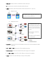
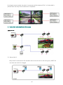
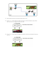
13. FIBER LINK: This LED will turn bright green once the TX and RX units are communicating correctly via fiber optic cable. IR and RS-232 Connection Diagram IR connection Connect the IR blaster cable to the TX’s IR connector. Connect the IR receiver cable to the RX’s IR connector. Put the remote control pointed to the IR receiver eye. Put the IR Transmitter Blaster eye pointed to the IR sensor of the AV source which is intended to be controlled by the remote control.