1
Loop testing
What IS the Loop and
why must it be tested?
Setting up the PDL 310
You must first understand that the loop to be tested includes the
supply system, so the mains must be switched on to carry out
When a fault occurs in an electrical system, the over-current device
a test.
must open the circuit to cut off current quickly. In domestic circuits
this device will be a miniature circuit breaker (MCB) or a fuse, both
of which operate when the current they carry exceeds the rated
value. The supply voltage drives this fault current, the value of the
current depending on this voltage and the resistance (strictly the
impedance) of the circuit in which it flows. A higher voltage or lower
impedance will result in a greater current and a faster time of
operation of the fuse or of the circuit breaker.
It is of the greatest importance that the circuit concerned is
disconnected as quickly as possible, to prevent dangers due to
Caution
We strongly advise reading and understanding
this guide before the instrument is used.
In particular note the safety issues that follow:■
Although fully protected up to 600V AC this tester
is for use on 230V AC circuits only.
■
Always check the tester on a known correctly wired
live socket outlet before and after use.
■
Before use - check your tester for any
damage to the plug, lead and cabinet.
electric shock or to fire. The supply voltage is fixed by the Supply
Company, so to achieve the greatest possible level of safety we must
ensure that the impedance of the path taken by the fault current is
low enough to ensure rapid operation of the protective device. This
path is called the earth fault loop, or sometimes simply the loop.
This loop may be extensive, going through the installation itself and
all the way back to the Supply Company’s transformer. The PDL 310
measures the impedance of this loop, and thus checks the safety of
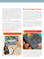
Plug the tester into a socket on the circuit to be tested as shown
in Figure 1.
the system.
The lower the loop impedance, the greater the fault current and the
more quickly the circuit is disconnected. So what should the value be?
Loop impedance values
There is no single, simple answer to the question “What is an
acceptable value for fault loop impedance?” The answer is, of
course, the impedance that will allow enough fault current to
operate the fuse or circuit breaker quickly enough to prevent
damage to the installation or to those using it. But this impedance
depends on the exact operating characteristics of the fuse or the
circuit breaker concerned, as well as on the rating of the device.
For example, a rewireable fuse requires lower loop impedance
than does a cartridge fuse, whilst the acceptable value is higher
for a miniature circuit breaker. Again, a 30 A fuse will require a
much lower loop impedance value than will a 5 A fuse.
Exact maximum values for loop impedance are to be found in
tables forming part of the IEE Wiring Regulations (BS 7671). This
publication can be difficult to interpret. A little later a simplified
explanation of the acceptable results will be given.
1
The PDL 310 connected ready for use