1
Switch the socket on, when the instrument will go through its
pre-test routine. The three LEDs in the orange triangle on the tester
Reversed Supply Polarity
will be a steady green accompanied by a series of bleeps while the
instrument sets itself up into its operating condition. If the LEDs are
It is seldom appreciated that the supply to an installation can be
not all green (indicating faulty wiring or connections), the tester will
misconnected so that the live (phase) and neutral/earth supply
automatically lock out to prevent further tests. Should any of the
conductors are reversed. This state of affairs is extremely rare, but
LEDs in the triangle be lit or flashing as red or orange accompanied
very dangerous indeed, because the live (phase) of the supply
by a warbling tone, this indicates a wiring fault, the nature of which
system will in many cases be connected directly to the earthing
is shown by the list on the front of the instrument and in more detail
system, so that all earthed metal will become live. If this mistake
by the table on the back of this Guide. This extremely valuable test
has been made there will be no obvious sign, with sockets and all
facility is built in to the PDL 310. Such faults may require assistance
equipment operating normally and most loop impedance testers
and advice to correct them.
will not show that a dangerous situation exists.
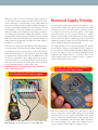
In the event of a socket not being available, the PDL 310 loop tester
The supply polarity can be verified by applying firm (thumb)
can be powered by connecting it to any suitable supply, possibly at
pressure onto the orange area at the bottom of the front panel of
a consumers unit, using a fused test lead set. Care must be taken to
the tester, which is labelled PRESS AND HOLD. Note that this
ensure that the brown lead is connected to the phase (live). Note
area does not depress as is the case with the ON/OFF, PFC and
this picture shows using the Socket & See ITLS 400 fused test lead
LOOP-PFC TEST buttons above it.
set, the blue neutral probe can be ‘piggy backed’ into the green
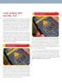
orange triangle remain green as shown in Figure 3, polarity is
(earth) unit and then a croc clip attached to the front of the green
correct and the loop test can proceed.
If the three LEDs in the
unit. Your tester is now a two wire testing device and measurement
can be made between phase-neutral or phase-earth.
WARNING: Always make the Neutral or Earth connection
before connecting to Phase.
2
3
The PDL 310 showing correct connections
and displaying the supply voltage.
The PDL 310 PLUS* connected to a consumers
unit using the fused test lead set supplied.
Below these indicators, the display screen will show the supply
voltage. In theory, the nominal supply voltage for the UK is 230
V, but in practice it is more usually around 240 V. If the supply
voltage is outside the permitted limits of 207 V to 253 V, the
tester will be automatically prevented from carrying out further
*Please note: the ITLS 400 test lead set is only included with
tests. In this (unlikely) event, expert help, probably from the
PDL 310 PLUS. It is an optional extra for standard PDL 310.
customers Supply Company, will be an urgent necessity.