1
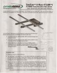
TwinTube® UBI™ Hitch Rack Platform
Part No. HMK901
User Assembly and Operation Manual
Congratulations on your purchase of TwinTube® UBI (U-Build-It™). The TwinTube® UBI system is a highly stable,
balanced, and strong receiver load carrying structure.
The TwinTube® UBI system features separate components that extend and
enhance the load carrying capabilities of a receiver style hitch.
•
The Spine assembly, which provides UBI’s structural strength and
telescope support.
•
The Frame assembly which provides UBI’s carrier, platform or box
mounting interface and telescoping function.
•
Safety Cable Quick Links allow the Frame and Spine system
components to be separated, thereby dividing the UBI’s weight in
half. This provides ease-of-use when installing or removing and
storing the system.
Installation Tips:
•
•
•
Keep this manual for future reference.
The TwinTube® UBI system fits a 2" size receiver style hitch and requires a minimum
of a Class II tow rating.
Keep in mind that the TwinTube® is a precision built product and some consideration
of “alignment” is necessary when first assembling the system. The TwinTube® uses
“symmetry” in a balanced manner, so when bolting the system together for the first
time, tighten all hardware in a two step process - first tighten the assembly to set the
components in position and then, when the TwinTube® is installed, securely tighten all
hardware.
U.S. Patent Numbers: 6,409,203; 6,609,725; 6,945,550;6,910,609; Patents Pending
HMK901 1214
Parts Identification
Parts List
ItemDescription
Quantity
A
Shank B V-Plates
C Top Plate
D Telescope Tubes
E Fixed Tubes
F Wings (44" C Channel)
G Top Hat Brackets
H 5/16” x 1 1/4” Carriage Bolts
J
Hexhead Silent Hitch Pin® Assembly K Hand Tighten Silent Hitch Pin® Assembly
L
Safety Cable with 2 Quicklink Connectors
M End Caps
N End Cap & Reflector Assembly
P 1/2" Bolts
Q 1/2" Washers
R 1/2" Locking Nuts
S 1/4" Washers
T 1/4" Locking Nuts
V Center Plate
W 1/4-20 x 1" Bolts
X Slide Bumpers
Paraffin Starter Wax
Z 5/16” Washers
AA 5/16” Nylock Nuts
1
2
1
2
2
2
Tools Needed
4
3/4" Wrench
8
3/4" Socket
1
1/4" Wrench or Socket
1
7/16" Wrench
1
1/2” Wrench or Socket
2
2
6
12
6
8
4
1
4
2
1
8
8
If you are missing any items, contact your sales agent if the product was assembled by them.
If not, or if purchased from Let’s Go Aero, please contact us at 1-877-GO-4-AERO (464-2376).
Spine Assembly
C
P
F
E
H
M
X
F
M
Q
H
E
H
D
X
R
B
G
D
T
N
S
U
T
N
A
T
V
Q
K
G
T
J
W
G
K
P
Q
R
K
G
Q
S
T
S
B
T
Q
S
P
L
Frame Assembly
Page 2 of 7
4
Silent Hitch Pin® Installation
Two Silent Hitch Pins are included with TwinTube® UBI
to prevent the inherent rattle that occurs when placing an
accessory device (in this case, TwinTube® UBI) into the
receiver hitch. The installation process is the same for
both Silent Hitch Pins, the Hexhead Silent Hitch Pin® (J)
secures the TwinTube® Assembly to the receiver hitch and
the Hand Tighten Silent Hitch Pin® (K) secures the Frame
Assembly to the Spine Assembly.
WARNING
Use Second Hole
unless more clearance is required 2
The V-Plate (B) with the Safety Cable hole goes on
the passenger side of the Shank (A). Orient both
V-Plates (B) so that they angle up and away from the
Shank (A) and the lower holes in the plates line up
with the 1/2" holes in the Shank. Install a 1/2" Bolt (P),
two 1/2" Washers (Q) and a 1/2" Locking Nut (R) in
each hole. Use a 3/4" Wrench and a 3/4" Socket to
position tighten the bolts.
V-Plates (B)
Safety Cable Hole
1/2" Locking
Nut (R)
Spring Nut
Note: Use the bolt hole in the Shank that places the
TwinTube® as close to your vehicle as possible. If
more clearance is needed use the last hole in the
Shank.
3.
Orient the Shank (A) with the two 5/8" holes toward
the receiver hitch on the vehicle. Insert the spring nut
from the Hexhead Silent Hitch Pin® Assembly (J) into
the Shank and line it up with the second hole from the
end of the Shank (A).
Shank (A)
2.
1
Spine Assembly
The Silent Hitch Pins® must be firmly tightened to work
properly. Make sure you use the Hexhead Silent Hitch
Pin® (J) to attach the Shank to the receiver hitch and
use a wrench to securely tighten it.
1.
3
1/2" Washer (Q)
Receiver
Hitch
1/2" Washers (Q)
1/2" Bolts (P)
Note: V-Plates MUST be attached angled AWAY from the
vehicle for product to install properly.
Slide the Shank with the spring nut installed into the
vehicle hitch and line up the Shank’s bolt holes with
the hole in the hitch.
Make sure the washer is on the Hexhead Silent
Hitch Pin® (J) and thread it into the threaded spring
nut. Use a wrench to securely tighten the Hexhead
Silent Hitch Pin® (J) to 30 ft. lbs – 60 ft. lbs. of torque
(equivalent to tightening a lug nut on a car wheel).
Install the pin clip from the assembly.
Pin Clip
Hexhead Silent
Hitch Pin
Washer
Shank (A)
Receiver
Hitch
4.
Place the Center Plate (V) between the V-Plates.
Install a 1/4-20 x 1" Bolt (W), two (2) 1/4" Washers (S)
and a 1/4" Locking Nut (T) in each hole. Then tighten
the bolts on the Center Plate.
1/4-20 x 1"
Bolts (W)
1/4"
Washers
(S)
1/4" Locking
Nuts (T)
1/4"
Washers (S)
1/4-20 x 1"
Bolts (W)
Page 3 of 7
5.
Place the Fixed Tubes (E) between the top of the VPlates (B) and place the Top Plate (C) on top. Install a
1/2" Bolt (P), two 1/2" Washers (Q) and a 1/2" Locking
Nut (R) in each hole (2 per Tube). Use a 3/4" Wrench
and a 3/4" Socket to position tighten the bolts.
11
7
5
10
Top Plate
1/2" Bolts (P)
1/2" Washers (Q)
9
1/2" Washers (Q)
8
9.
1/2" Washers (Q)
Securely tighten the bolts that attach the Fixed Tubes
(E) to the V-Plates (A). Make sure that the bolts are
so tight that it is difficult to tighten them further using
hand tools.
Caution
Fixed Tubes (E)
1/2" Locking
Nuts (R)
6.
7.
1/2" Bolts (P)
Securely tighten the bolts that attach the V-Plates (B)
to the Shank (A). Make sure that the bolts are so tight
that it is difficult to tighten them further using hand
tools. Then snug tighten the bolts on the Center Plate
to 12 ft. lbs.
Periodically check that the bolts are tight to ensure
TwinTube® performs as designed.
10.
Place a Slide Bumper (X) over each Fixed Tube and
slide them back against the Top Plate.
Rub the top, sides and corners of the Spine’s
Fixed Tubes (E) with the enclosed bar of Paraffin
Wax. This reduces friction, provides telescope
smoothness, and protects the powder coated paint
from wear. You will find that TwinTube’s Paraffin Wax
is a great solution to clean, hassle-free operation.
Once applied, it stays put and stays clean.
Rub top, sides and corners
with Paraffin Wax
Fixed Tubes (E)
Slide Bumpers (X)
Frame Assembly
8.
11.
Insert the spring nut from Hand Tighten Silent Hitch
Pin Assembly (K) into the Telescope-Safety pin hole
on one of the Fixed Tubes (E). Line up spring nut hole
with the Telescope-Safety Pin hole.
Note: It does not matter which Fixed Tube is used.
Locate the Telescope Tubes (D) and orient them to
the Spine Assembly with the weld seam down and
with the hole away from the Spine. The hole in each
Telescope Tube (D) must line up with the hole in the
Fixed Tube (E).
Telescope Tubes (D)
Either Fixed Tube
may be used
Telescope Safety Pin Hole
Spring Nut from Hand
Tighten Silent Hitch Pin
Holes must align
Page 4 of 7
12.
12 13
The two 44" Wings (F) form the mounting surface of
the TwinTube UBI®. The Wings are adjustable for
different platform widths, but they must be at least
12” apart to support a load properly.
The first Wing (F) should be mounted as close
to the Top Plate (C) of the Spine Assembly as
possible, depending on spare tires or ladders on
the vehicle.
To mount this Wing, place four 5/16” Carriage Bolts
(H) with 1” Bolts running through the pre-drilled
square mounting holes in the bottom of the Wing
channel and position the Wing on the Telescope
slide tubes. Thread a Carriage Bolt (H) through the
Safety Cable on the passenger side and a Top-Hat
Bracket (G) over the Carriage Bolt threads. Secure
the Brackets with a 5/16" Washer (Z), and a 5/16”
Nylock Nut (AA) at each Carriage Bolt.
Caution
The Wings must fit squarely on the Telescope Tubes
for the Bolts to tighten correctly and for the telescope
feature to operate freely. Tighten the Top Hat Brackets so
that the ears deflect into a slight bend.
WARNING
The 44" Wings must be at least 12" apart to support a
load properly.
44" Wing (F)
14
14.
5/16” x 1 1/4” Carriage Bolts (H)
Top-Hat
Bracket (G)
5/16” Washers (Z)
and 5/16” Nylock
Nuts (AA)
5/16" Washers (Z)
13.
Note:
Top-Hat Bracket (G)
5/16” Nylock
Nuts (AA)
Check that the Telescope Tubes (D) are as
far toward the vehicle as possible and that the
Telescope Pin holes in the rear of the Spine and
Telescope Tubes (D) are aligned. When everything
is aligned, tighten the 5/16” Nylock Nuts(AA) on
the Carriage Bolts(H). Tighten the 5/16” Nylock
Nuts alternating from side to side so each side of
the Top-Hat Bracket is equally compressed around
the Telescope Tube (D). Use a 1/2" wrench to snug
tighten the nuts to 12 ft. lbs.
Slide the Frame back and forth on the Spine to
check the alignment. If any binding is observed,
check to be sure that the Telescope Tubes (D) both
come to rest against the Top Plate on the Spine and
that the Wing is mounted “squarely”. If not, loosen
the Top Hat Bracket fasteners and reposition the
Wing (F).
Repeat Steps 12 and 13 with the rear Wing (F).
Leave the Carriage Bolts (H) and Nylock Nuts (AA)
loose enough so the Wing can move forward or
back as needed to fit the bolt hole pattern of the
platform you intend to mount on UBI. You may
adjust both Wings along the Frame tube as needed
to accommodate your platform of choice, as well
as for additional clearance to accommodate spare
tires, etc. on the back of your vehicle.
After installing your platform of choice to the Wings,
the last step is to firmly tighten all the 5/16 Nylock
Nuts securing the Top-Hat Brackets to the Wings.
Tighten these in a balanced fashion until securely
snug. Between uses, periodically re-check these
fasteners for proper tightness.
44" Wing (F)
5/16” Carriage Bolts (H)
Top-Hat
Bracket (G)
5/16” Washers (Z)
and 5/16” Nylock
Nuts (AA)
Top-Hat Bracket (G)
5/16” Washers (Z) and
5/16” Nylock Nuts (AA)
Page 5 of 7
15.
Attach the Safety Cable (L) to the passenger side
V-Plate (B) with the hardware attached to the cable.
This will ensure that the Frame cannot slide off
the Spine inadvertently. To remove the Frame and
carrier from the Spine, simply undo one Quick Link.
This allows TwinTube® to be separated into its two
component parts to ease the installation, removal
and storage. of the system.
16
15
16
Safety Cable (L)
17
17.
V-Plate (B) Passenger Side
16.
Install the End Caps (M) without reflectors into the
ends of the Fixed Tubes (D) closest to the vehicle
and the End Cap and Reflector Assemblies (N)
into the ends of the Telescope Tubes at the rear
of TwinTube® (farthest from vehicle for view from
behind).
The Hand Tighten Silent Hitch Pin® (K) with the
handle is for securing TwinTube’s Frame to the
Spine during use. When this pin is engaged, it
helps prevent carrier movement or wobble. When in
transit, it prevents the Frame from sliding rearward
on the Spine. Be sure to use the 1/4" x 5/8" nylon
bushing on the Silent Hitch Pin® assembly to
prevent any scratching or marring of the powder
coated finish on the Telescope Tube (D). To install,
thread the Hand Tighten Silent Hitch Pin® (K) into
the spring nut that was installed in Step 6. Install
the pin clip from the assembly.
Pin Clip
Hand Tighten Silent
Hitch Pin (K)
End Caps (M)
Nylon Bushing
End Cap and Reflector
Assemblies (N)
WARNING
Note: Up to 6” of additional rear rack clearance may be
achieved by setting the Wings rearward along the
TwinTube as shown below. Do NOT position beyond
the Telescope Bolt hole location; the Hand-Tighten
Silent Hitch Pin must remain rearward of the Wings
at all times.
The Hand Tighten Silent Hitch Pin MUST be firmly secured
in Telescope-Safety pin hole location before transit. Failure
to do so may result in potential hazards from improper
operation, including property damage and bodily injury.
WARNING
Never move your vehicle with the TwinTube® UBI extended in the telescoped position. It must always be properly
secured before transit. Failure to do so may result in
potential hazards from improper operation, including property damage and bodily injury.
Page 6 of 7
Safe Use & Operation
This information is pertinent to TwinTube® UBI and any platform it supports including carriers
by Let’s Go Aero. Be sure to follow these guidelines to prevent possible hazards from misuse.
Vehicle and Hitch Receiver Compliance
This TwinTube® UBI hitch rack fits 2" size hitch receivers and is rated for a Class II tow capability or higher (Class II, III
and up). When operating a tow accessory (any item inserted into the hitch receiver), you must comply with the vehicle and
hitch receiver’s towing parameters. Consult your vehicle and hitch receiver owner manual(s) for details on your tow and
tongue weight parameters. Be sure that they are compatible with TwinTube® UBI and your platform of choice’s weight
specifications.
Tongue Weight Compliance
TwinTube® UBI and any platform installed on this support structure creates a combined weight that creates direct downward pressure on the hitch receiver’s tongue. This downward pressure is the tongue weight. Tongue weight is one of the
two critical weight rating factors of your tow rating’s classification (Class I, II, III, IV, V). Never exceed your vehicle and
hitch receiver’s tongue weight specification.
TwinTube® UBI Weight and Load Parameters
TwinTube® UBI weighs 48 lbs unloaded. To determine your available load weight in accordance with your vehicle and
hitch receiver’s tongue weight rating, subtract TwinTube’s 48 lbs from your identified tongue weight rating. The difference
represents your vehicle and hitch receiver’s available load weight.
TwinTube® UBI is rated for up to 300 lbs of carrying capacity. This weight includes any platform installed on TwinTube®
UBI as well as the cargo itself.
When transporting cargo, place heavy loads in the center and lighter cargo to the outside. The 44" Wings must be at least
12" apart to support a load properly.
The rearward load length should not exceed the overall surface space provided by the TwinTube® UBI structure. The
Wings are adjustable; however, always keep the load as close to the vehicle as possible. Keep in mind that the further
your load is from the hitch receiver, the greater your downward pressure (tongue weight). For each one foot rearward,
approximately twenty percent of your hitch receiver’s tongue weight is diminished
Telescoping TwinTube® UBI
To telescope the TwinTube® UBI, remove the Hand Tighten Silent Hitch Pin® from the Telescope Safety pin hole. Verify
that the Safety Cable is secured and then slide the frame to the rear.
WARNINGS
Failure to adhere to these recommendations may result in potential hazards from improper operation, including property damage and bodily injury.
• Engage Silent Hitch Pins®
Both pins MUST be securely engaged before transit. A wrench MUST be used to tighten the Hexhead
Silent Hitch Pin® at the hitch receiver location.
• Secure the TwinTube® UBI as close to vehicle as possible
Always secure TwinTube® UBI as close to your vehicle as possible, minimizing the distance of this
structure and its load from your vehicle. There are two bolt hole settings (5 3/4" and 8" positions) from
which to choose. You may also adjust the Wings for up to 10" of rear installed clearance from your
vehicle as needed. See Step 10 of this User Manual for Wing adjustment.
• Verify that the Safety Cable is Secured
The Safety Cable prevents the Frame from sliding off the Spine when telescoping the TwinTube®. It
should always be engaged for this reason, and to prevent the cable from dragging on the ground while
in transit.
• Never move your vehicle with the TwinTube® UBI extended in the telescoped position.
The TwinTube® UBI must always be properly secured before transit.
We warrant this product to the first consumer to be free from defect in material and workmanship for one year (Please retain your sales slip for your records).
Any product or part thereof found to be defective within that period will be replaced without charge provided that: (1) the product was not misused; (2) no
alterations or modifications were made; (3) its failure resulted from a defect in material or workmanship and not from normal wear expected in the use of
the product; (4) the product or part is delivered, freight prepaid, to Let’s Go Aero. Please contact Let’s Go Aero, toll free, at 877-464-2376 to get a return
authorization number prior to return. Manufacturers only obligation shall be to replace such products or parts proved to be defective.
© Copyright 2014 Let’s Go Aero Inc
Page 7 of 7