1
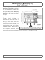
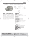
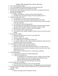
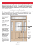
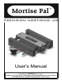
User's Manual
Revision-D
COPYRIGHT © 2007-2008 BY R.G. Jig Co.
WARNING: NO PORTION OF THIS MANUAL MAY BE REPRODUCED IN ANY SHAPE
OR FORM WITHOUT THE WRITTEN APPROVAL OF R.G. Jig Co.
Mortise Pal™ Mortising Jig
User's Manual
Mortise Pal™ allows you to make precision slot mortises with your plunge
router. Please take the time to thoroughly read this manual and familiarize
yourself with how the jig is used as well as the jig's safety precautions.
Kit Contents:
As shown in Fig. 1, the jig is supplied with:
●
(1) Jig Body
●
(4) Mortising Templates
●
(1) Doweling Template
●
(1) 5/8” Template Guide Bushing* with Nut and Centering Pin
●
(1) 3/32” Hex Key
*Note:
The
supplied
template guide bushing
fits Porter Cable style
base plates. Check your
users
manual.
Others
will require a universal
base plate adapter (not
included).
Fig. 1: Kit Contents
1
Mortise Pal™ Mortising Jig
User's Manual
Required Items:
To use the jig you will be required to supply:
●
A light duty plunge router with a 6” base plate. These routers are
generally 2-1/4 horsepower or less and weigh less than 12 pounds.
The jig is not designed for and should not be used with heavy duty
plunge routers. Various factors such as their overall size, weight, and
center of gravity make heavy duty plunge routers unsuitable for use
with this jig.
●
A router bit. Spiral up-cut bits are recommended as they remove
waste from the mortise while routing.
Safety:
To operate this or any tool safely and efficiently, it is essential to become as
familiar as possible with its characteristics. Take as much time as necessary
to become familiar with the jig. Also, read and follow all of the safety
procedures noted in this manual. If you do not understand any of the
operations or safety guidelines discussed in this manual, please get answers
to all your questions before attempting to use the jig by emailing
[email protected] or calling 619-459-7951.
Read, understand, and follow all of the safety instructions that were included
with your plunge router.
This jig should only be use with a plunge router. Never use the jig with a fixed
base router.
The jig is designed to be used with plunge routers that have base plates that
2
Mortise Pal™ Mortising Jig
User's Manual
are at least 6” in
diameter. Referring to
Fig. 2, your plunge
router's base plate
must be supported by
by the jig's fence and
the
jigs
clamping
bracket at all times
during
use.
Before
using the jig, check to
see that your plunge
routers base plate is
supported
by
the
Fig. 2: Your plunge router base plate is supported by
the jig's fence and clamping bracket.
fence and clamping
bracket with the template positioned anywhere along the guide rods. If
your base plate is not supported by the jigs fence and the jigs clamping
bracket do not use the jig as this can create problems with your joinery,
damage the jig or create an unsafe situation.
Referring to Fig. 3, some
base
plates
completely
are
circular
not
or
have an offset clearance
hole or both. Care must
be taken when using
these plunge routers to
ensure that the widest
Fig. 3: Some base plates are non-circular or have
offset clearance holes.
3
Mortise Pal™ Mortising Jig
User's Manual
portion of the plate is at least
6” and maintains contact with
the jigs fence and clamping
bracket at all times as shown
in Fig. 4.
Proper
stock
holding
is
essential for the safe use of
the jig. Your stock must be
held securely with clamps, in a
woodworkers vise, or by other
suitable means. Stock that is
not properly secured could
Fig 4: Use widest portion of plate when it is
not circular or has an offset clearance hole.
move while routing, creating an unsafe situation or damaging the jig.
4
Mortise Pal™ Mortising Jig
User's Manual
When
using
a
woodworker's vise avoid
clamping the jig to your
stock
as
shown
in
Figures 5 and 6. The jig
is shown clamped to the
stock
with
too
much
distance between the jig
and the vise jaws. Forces
generated from routing
could leverage the stock
Fig 5: Unsafe Vise
Setup.
and cause it to move.
Fig. 6: Unsafe Vise Setup.
5
Mortise Pal™ Mortising Jig
User's Manual
Figures
7
and
8
illustrate a safer setup
when clamping stock in
a woodworkers vise.
The stock has been
repositioned so that the
jig is closer to the vise
jaws. Forces generated
from routing are less
likely to leverage the
stock.
Fig. 7: Safe Vise Setup.
Fig. 8: Safe Vise Setup.
6
Mortise Pal™ Mortising Jig
User's Manual
Specifications:
Referring to Fig. 9:
●
The minimum
stock
is
width
1”.
Your
stock needs to
be at least 1”
wide
to
Fig. 9: Stock and mortise specifications.
be
securely clamped in the jig.
●
The minimum stock thickness is 3/4”. Note, mortises may be made
in thiner stock by using shims.
●
The maximum stock thickness is 3”.
●
The maximum mortise width is 1/2” as determined by the largest bit
to fit through the 5/8” outside diameter template guide bushing.
●
The mortise length is determined by the template used and the
diameter of the router bit used. Referring to Fig. 10, the template
length is measured from center to center along the
slot. The
mortising templates supplied with the jig come in four lengths, 1/2”,
1”, 1-1/2” and 2”.
●
To determine
the
overall
mortise length
add
the
template
length to the
bit
diameter.
Fig. 10: Template Specifications.
For example,
7
Mortise Pal™ Mortising Jig
User's Manual
the 1” template used with a 3/8” bit produces a 1-3/8” mortise. The
same template used with a 1/4” bit produces a 1-1/4” mortise. Table
1 can be used to determine the overall mortise length for common
sized router
bits. Note, by
overlapping
mortises it is
possible
to
create
mortises
Template Length (in)
1/2
1
1 1/2
2
Bit Diameter (in)
3/4
1 1/4
1 3/4
2 1/4
1/4
Mortise Length (in)
13/16”
7/8
1 5/16”
1 3/8
1 13/16”
1 7/8
2 5/16”
2 3/8
5/16”
3/8
1
1 1/2
2
2 1/2
1/2
Table 1: Mortise length equals template length plus
bit diameter.
of
virtually any length. Referring again to Fig. 8, the template width is
41/64”, or 1/64” larger than the 5/8” template guide bushing. This
small space between the bushing and the template allows you to
rout the mortise by moving your router around the template thereby
producing a mortise with an excellent surface finish on the walls.
Just remember that your finished mortise will be 1/64” larger than the
bit diameter.
Using the Jig:
Using the jig generally requires the following five steps:
1. Install the template guide bushing.
2. Select and install a template.
3. Make layout lines on your stock.
4. Set up the jig.
5. Rout the mortise.
8
Mortise Pal™ Mortising Jig
User's Manual
Step 1. The template guide bushing includes a centering pin that allows
you to install it perfectly
concentric
plunge
your
routers
Referring
insert
with
to
the
collet.
Fig.
11,
appropriate
end of the centering pin
into your plunge routers
1/4”
or
1/2”
collet.
Tighten the collet. Then
Install
the
guide
template
bushing
by
placing it into the counter
bore
of
your
plunge
Fig. 11: Template Guide Bushing, Nut and
centering Pin.
router's base plate. Thread the nut onto the template guide bushing, but do
not completely tighten the nut. Plunge the centering pin through the
bushing so that the center portion of the pin mates with the inside diameter
of the bushing. Lock your plunge router at this depth and tighten the nut.
Then retract the centering pin and remove it. The template guide bushing
is now installed perfectly concentric with your plunge routers collet.
9
Mortise Pal™ Mortising Jig
User's Manual
Step 2. Referring to Fig. 12, select a template and then install it by first
removing the brass screws. Use the 3/32” hex key that was included with
the jig. Place the template onto the template block so that the holes in the
template mate with the
corresponding
dowel
pins on the template
block.
Press
down
firmly to ensure that the
holes in the template
mate with the dowel
pins. Carefully replace
the brass screws. To
remove the template,
remove
the
screws,
insert
brass
your
Fig. 12: Install template by removing brass
screws and placing template over dowel pins
index finger into the slot
on the template and pull it off of the template block.
Step 3. Make layout lines on your stock that mark the center of the mortise.
Fig 13 shows the completed layout lines on a leg blank before the mortise
has been routed.
10
Mortise Pal™ Mortising Jig
User's Manual
Step 4. Setting up the jig will require
centering the template over the layout
lines. Referring to Fig. 14, hold the jig's
fence
against
your
stock. Align
the
centerline mark on the side of the jig with
the first layout line as shown. When the
centerline mark and the layout line
coincide, turn the thumb screw to lock the
template in place.
Fig. 13: Make layout
lines marking the center
of the mortise.
Fig. 14: Align centerline mark with first layout
line.
11
Mortise Pal™ Mortising Jig
User's Manual
Referring to Fig. 15
align the centerline
pointer
with the
second layout line.
Then
turn
the
clamping knob so
that
the
secured
stock
is
to
the
with
the
template
over
jig
the
centered
layout
lines.
Fig. 15: Align centerline pointer with second layout
line.
Step 5. Proceed to rout the
mortise. Referring to Fig. 16,
one technique for routing the
mortise is to make a series
of overlapping plunges to full
depth along the length of the
template.
Then
make
a
finishing cut by moving your
plunge router around the
template. This technique is
fast and produces a mortise
Fig. 16: Overlapping plunge cuts.
12
with an excellent surface
Mortise Pal™ Mortising Jig
User's Manual
finish on the walls.
Note, waste chips will accumulate while routing the mortise. You may need to
periodically stop routing and remove this waste. A shop vacuum works well.
Maintenance:
The jig requires very little maintenance. To remove dust and debris from the
jig use compressed air, a soft bristle brush or a dry rag. Periodically place a
drop of lubricant or tool oil on the four stainless steel guide rods.
Warranty:
R.G. Jig Co. stands behind its products with a one-year limited warranty. If
you have any questions regarding the warranty you can contact Customer
Service by email at [email protected] or by calling 619-459-7951.
Coverage:
R.G. Jig Co. warrants that this product is free of defects in factory
workmanship and materials during normal use. If this product fails during
normal use because of such a defect, R.G. Jig Co. will, at its option, repair or
replace, free of charge, any part or parts shown to be so defective.
Excluded from Coverage:
Failure resulting from alteration, modification, misuse, abuse or neglect or
after repairs have been attempted or made by others.
13