1
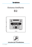
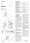
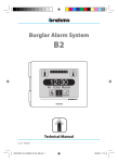
GSM communicator
BXGM0001
Installer and User manual
05-02-10/24852600
BXGM0001 24852600 05-02-10_EN.indd 1
05/02/10 10:38
Use and Applications
The modules consists of a telephone communicator on a GSM network for BRAHMS model burglar
alarms
B2UC0002
The device lets you remotely control the main functions (activation, deactivation, sectioning, etc.)
of the BRAHMS burglar alarm where it is installed by sending SMS messages.
The communicator, when properly programmed, is capable of sending voice or SMS messages (or
both) which inform the user of events that have occurred that concern the system.
The SMS messages that are sent to the GSM module can be customised, allowing them to be
memorised and subsequently transmitted more easily, or written in a different language from the
default one (Italian).
The customisation can be carried out using the SMS messages described in the column highlighted in the table (customised SMS sent by the User), where in place of the word “Comment”, a
customised text can be added.
The device is also equipped with a normally open relay contact which can be used to activate
TH Bpt heat regulators designed for remote control or any other device set up for this purpose,
controlled through the opening or closing of a contact.
By adding the optional card BXGMOH01 you can use the module in “mixed” BRAHMS burglar
alarm systems in conjunction with BPT HOASIS home automation systems.
m ATTENTION
• The BXGM0001 dialler is compatible with B2UC0002 equipped with terminals of version 1.0 or
greater.
The version of the terminal can be obtained from the packaging label, from the label on the back
of the terminal, or it can be read directly on the screen by pressing the button .
2
BXGM0001 24852600 05-02-10_EN.indd 2
05/02/10 10:38
Index
Use and Applications . . . . . . . . . . . . . . . . . Page 2
Safety warnings . . . . . . . . . . . . . . . . . . . . . . . Page 4
Installer instructions
User instructions
General technical characteristics . . . . Page 6
Contents of package . . . . . . . . . . . . . . . . . . . . . . . . . 6
Functions that can be performed
by SMS . . . . . . . . . . . . . . . . . . . . . . . . . . . . . . . . . Page 22
Installation of the SIM card and
the optional card BXGMOH01 . . . . . . . . Page 7
Messages to user by voice and SMS
for B2 control units . . . . . . . . . . . . . . . . . . . Page 24
Positioning of the device . . . . . . . . . . . . . Page
Assembly of the antenna . . . . . . . . . . . . . . . . . . . . . Assembly in the plastic container
B2CTPL01 on BRAHMS B2 control unit. . . . . . . . Assembly in the metallic container
B2CTME01 on BRAHMS B2 control unit . . . . . . . Reminder of the communicator
settings . . . . . . . . . . . . . . . . . . . . . . . . . . . . . . . Page 25
8
8
8
8
Terminal boards and connectors . . . . . Page 9
Commissioning . . . . . . . . . . . . . . . . . . . . . . . Page 10
Connection diagrams . . . . . . . . . . . . . . . . . Page 11
Programming of the communicator
through SMS . . . . . . . . . . . . . . . . . . . . . . . . . . Page 14
Create an address book . . . . . . . . . . . . . . . . . . . . . . 14
Add a telephone number to the address book. . . 15
Modify a telephone number
in the address book. . . . . . . . . . . . . . . . . . . . . . . . . . . . . . . . . . 15
Deletion of a telephone number
in the address book. . . . . . . . . . . . . . . . . . . . . . . . . . . . . . . . . . . 15
Use of special telephone numbers
in the communicator. . . . . . . . . . . . . . . . . . . . . . . . . 15
Find out your remaining SIM credit . . . . . . . . . . . 15
Deactivate SMS reception by
a number in the address book . . . . . . . . . . . . . . . 16
Programming of the General Preferences of
the communicator through SMS . . . . . Page 17
Communications attempts. . . . . . . . . . . . . . . . . . . 17
Cyclical sequence. . . . . . . . . . . . . . . . . . . . . . . . . . . . . 17
End cycle of calls . . . . . . . . . . . . . . . . . . . . . . . . . . . . . 17
Dialling pause. . . . . . . . . . . . . . . . . . . . . . . . . . . . . . . . 17
Default parameters on module. . . . . . . . . . . . . . . 18
3
BXGM0001 24852600 05-02-10_EN.indd 3
05/02/10 10:38
Safety Warnings
m ATTENTION
• After removing the packaging, check the condition of the unit.
• The packaging items (plastic bags, expanded polystyrene, etc.) must not be handled by children
as they may be dangerous.
• Carefully read the instructions before starting installation. Perform work as specified by the
manufacturer.
• Before connecting the equipment, make sure that the rating plate data corresponds to that of
the distribution network.
• An omnipolar switch, with contacts separated by at least 3mm, must be installed upstream on
the equipment, on the electric system of the building.
• The manufacturer declines all liability for any damage as a result of improper, incorrect or unreasonable use.
• Before performing any cleaning or maintenance operation, disconnect the equipment from the
power supply network by opening the system switch.
• In case of failure and/or malfunction of the device, detach it from the power supply and do not
tamper with it.
• Use original spare parts.
• Installation, programming, commissioning and maintenance of the product must only be performed by qualified technicians who have been properly trained in compliance with current
standards including compliance with accident prevention.
• Operate in sufficiently lighted areas that are conducive to health and use tools, utensils and equipment that are in good working order.
• Upon completion of installation, always check for correct operation of the unit and the system as a
whole.
• Do not install the device outdoors or in areas where it is exposed to seepage or splashes of water.
• Handle the device with care. It contains electronic parts that are fragile and sensitive to humidity.
• The electronic cards can be seriously damaged by discharges of static electricity. If they are to be
handled, wear suitable clothing and anti-static footwear, or at least, ensure static electricity has
been discharged by touching with the fingertip a metallic surface connected to the earth system
(e.g. the chassis of a household appliance).
• Weld the joints between wires to prevent false alarms caused by oxidation of the wires.
• The electrical system must comply with current standards in the country of installation.
• Failure to comply with the above instructions may compromise the unit’s safety.
• The installer must make sure that the information for the user, where applicable, is present on the
devices.
• Dispose of the unit in accordance with current standards.
4
BXGM0001 24852600 05-02-10_EN.indd 4
05/02/10 10:38
Installer instructions
BXGM0001 24852600 05-02-10_EN.indd 5
05/02/10 10:38
Package contents
· GSM module
· Instructions
· DIN rail
· Antenna
45
The communicator BXGM0001 is contained
in a DIN70 module which can be fastened in
the spaces provided in the containers of the
BRAHMS burglar alarm control units or in any
electrical enclosure provided with DIN rails.
106
General technical characteristics
43,5
70
57
145
7,5
70
64,5
Technical specifications of the communicator
Weight
160 grams
Container material
PPOX (Polypropylene oxide)
Degree of protection
IP 30
Power supply
15 V AC or from the 12 V DC supply line
Standby consumption
310 mA with 15 V AC –– 110 mA with 12 V DC
Communication consumption
360 mA with 15 V AC –– 180 mA with 12 V DC
GSM module type
Modem GSM/GPRS Dual Band 900/1800 MHz
Operating temperature
from +0 °C to +40 °C
Storage temperature
-10 °C to +60 °C.
Relative Humidity
< 90% without condensation
6
BXGM0001 24852600 05-02-10_EN.indd 6
05/02/10 10:38
Installation of the SIM Card and the optional card BXGMOH01
In order to operate, the device must be equipped with a SIM card, not included in the package, to
be inserted in the appropriate housing.
The device can work in conjunction with the Hoasis Bpt home automation system by adding the
interface module (optional)BXGMOH01 to be assembled as shown in the figure.
To do this, unscrew the two fastening screws and remove the dialler cover. Do this making sure that
you do pull out the antenna wire.
SIM card not included
SIM card housing
Optional module BXGMOH01
for interfacing with Hoasis+ BPT
home automation system
m ATTENTION
• If the SIM card is new, prior to inserting it into the communicator, make a call by inserting it
into a mobile phone thus allowing the mobile telephone operator to register the card.
• The device requires that the SIM cards are activated only vocally and by SMS (No SIM Data!)
• Before carrying out the programming operation, deactivate the SIM card PIN code.
c ATTENTION!
The electronic cards can be seriously damaged by discharges of static electricity. If they are to be
handled, wear suitable clothing and anti-static footwear, or at least, ensure static electricity has been
discharged by touching with the fingertip a metallic surface connected to the earth system (e.g. the
chassis of a household appliance).
7
BXGM0001 24852600 05-02-10_EN.indd 7
05/02/10 10:38
Positioning of the device
Assembly of the antenna.
On the shell of the module, there is a seat for
the insertion of the antenna included in the
package.
The antenna provided is swivel type so that it
can be placed in any non-metallic container.
If the module is installed inside a DIN box,
move the seat of the antenna into the appropriate additional hole on the shell, thus allowing its correct closure.
Fig.1
Assembly in the plastic container
B2CTPL01 on BRAHMS B2 control unit
Assemble the DIN rail provided on the bottom
of the container, screwing it into the holes and
fasten the module (fig.1).
Assembly in the metallic container
B2CTME01 on BRAHMS B2 control unit
Assemble the DIN rail provided on the bottom
of the container, screwing it into the holes and
fasten the module (fig.2).
Fig.2
m ATTENTION
If the module is installed inside metal containers, use the optional antenna model BXANGM01 by placing it outside the container
as shown in figure 2.
Fig.3
8
BXGM0001 24852600 05-02-10_EN.indd 8
05/02/10 10:38
Terminal boards and connections
RS 232 connector to interface
the module with a PC
Optional auxiliary
battery connector
Green LED:
Voltage present
CN1
M2
Yellow LED
GSM transmission/reception
in progress
CN4
DL1
3
2
Red LED
transmission/reception
on line BUS B2 in progress
Connection
for antenna
SIM Card
SIM Card housing
connector
for assembly
of card Hoasis BPT
Jumper SW1
TAMPER disabled
CN5
B2
C
NO
TAMPER
TMP
LCK
DFT
BTL
LA
M1
BUS
LA
Terminals
BUS - LA
BUS - B2
M1
C, NO
TAMP
BUS
B2
C N0 TAMP
Jumper SW4
boot loader
Jumper SW3
default reset
Meaning
Terminal board for Bpt BUS Hoasis connection
Terminal for connection to BUS B2 BRAHMS
Relay contact 12V 1A (normally open)
Terminal board for TAMPER contact connection
Terminal board for earth connection
M2
SW1
SW2
SW3
SW4
SW1
SW2
SW3
SW4
Jumper SW2 address
book protection
TMP
LCK
DFT
BTL
Terminal board for connection to power supply from power supplier
When the jumper is connected the tamper contact is disconnected
When the jumper is disconnected the address book cannot be modified via SMS
By powering the module without jumper the default configuration is reset
Boot-loader (jumper reserved for the Technical Service not to be removed)
9
BXGM0001 24852600 05-02-10_EN.indd 9
05/02/10 10:38
Commissioning
m ATTENTION
Before installing the module it is important to verify that there is an adequate radio receiving signal
from the device in the area where the device needs to be installed.
To do this, simply insert the SIM in a mobile phone and check reception.
If reception is poor the device will have to be installed in another location with a better signal.
Please be informed that the company Brahms S.r.l. declines all liability in the event of:
• failed transmission, failed reception, delayed transmission or delayed reception of SMS messages by the communicator, when these are due to the quality of the reception signal or to
any other problem related to the mobile telephone operator’s activities.
• charging cost on the communicator remaining SIM credit resulting from messages sent by
the mobile telephone operator or from other services carried out by the mobile telephone
operator.
Once the module has been placed in the appropriate containers, as described in the previous
pages, proceed as follows:
• Ensure voltage has been removed to the system.
• Connect the communicator to the system BUS by means of the terminal BUS B2.
• Connect the terminals to the power supplier of the system B2 or to the terminals of the control
unit (as shown on the diagrams of the following pages).
• Now restore voltage to the system.
• The lighting of the green LED indicates that the module is powered.
• The yellow LED, will remain on for a few seconds, during which the GSM device will verify mobile
reception.
If after a few seconds the yellow LED switches off the operation was successful. If, on the
contrary, the yellow LED remains on this may indicate that there are GSM communication
problems, related to reception failure or SIM card registration (see the chapter “Sim Card
Assembly”).
Once the installation has been completed the yellow LED will flash only in case of data transmission/reception on the GSM network.
m At this point of installation it is essential to “teach” the device, following the instructions
for installation of the burglar alarm system to which the GSM module is connected.
If the red LED flashes, it means that communication on the BUS line is active.
10
BXGM0001 24852600 05-02-10_EN.indd 10
05/02/10 10:38
Diagrams for connection to Brahms B2 systems
BXGM0001
M1
NO
C
BUS LA
TH/450
BUS B2
TH450
M2
A questo contatto possono
essere connessi cronotermostati
Bpt TH/450 - TH/350 - TH/125,
o qualunque altro dispositivo
controllabile da remoto mediante
apertura/chiusura di un relè.
B2AL0001
M2
B2SEAL02
24 V
30 V
BUS
12 V
BUS
M1
+
–
+
B2IPPA01
BAT –
TAMPER
BUS
BB065
–
+
B2UC0002
BB065
BUS
–
+
230Vac
Fig.4
11
BXGM0001 24852600 05-02-10_EN.indd 11
05/02/10 10:38
Connection of BXGM0001+ card BXGMOH01 in mixed system comprised
of Hoasis+ BPT home automation - Brahms B2 burglar alarm
OH/A.01
OH/RI
M3
LA
LA
LA
OH/MA
BXGSM001
BUS LA
LA
M1
BUS B2
OH/T.01
M2
B2AL0001
B2SEAL02
M2
24 V
BUS
30 V
BUS
M1
B2IPPA01
+
12 V
–
+
BAT –
TAMPER
BUS
BB065
B2UC0002
–
+
BUS
BB065
–
+
230Vac
Fig. 5
m ATTENTION
If the GSM module is installed in “mixed” systems of BRAHMS B2 and HOASIS BPT, is it necessary to
install on the module BXGM0001 the card BXGMOH01 (optional) so that the module can interface
with both systems.
12
BXGM0001 24852600 05-02-10_EN.indd 12
05/02/10 10:38
BXGM0001 connection to Bpt series TH programmable thermostats
BB008
+
–
OH/GSM
CN1
TH....
M1
TH450
NO
C
BUS LA
1
2
BUS B2
Programmable thermostats can be
connected to this contact, such as
Bpt TH/450 - TH/350 - TH/125,
or any other device that can be remotely
controlled via the opening/closing of
a relay.
M2
15 V
230 V
TRANSFORMER
Fig. 6
230Vac
The device is equipped (terminals C, NO of terminal board M1) with a relay contact that can be
used to activate any controllable device by opening or closing a contact. Specifically, with the
message “-password-25 <Comment>” you can control impulse contact devices, such as the heat
regulators of the series TH Bpt set up for remote control (TH/125 - TH/350 - TH/450).
Function
Customised SMS sent
by the User
-password-23 <Comment>
-password-24 <Comment>
Closing of the dialler auxiliary contact relay
Opening of the dialler auxiliary contact relay
Closing of the dialler auxiliary contact relay for 3 seconds
-password-25 <Comment>
for activation of Bpt programmable thermostats
Relay status request
-password-26 <Comment>
Reply SMS to
the User
RELAY ON
RELAY OFF
RELAY TH ON
RELAY ON
RELAY OFF
. Note:
The “-password-25 <Comment>” command, sent to Bpt programmable thermostats, activates a
specific programm. For more details refer to the programmable thermostats manuals.
For instance, in order to close the auxiliary contact relay the following SMS can be customized
and used:
-password-23 <CLOSE RELAY>
13
BXGM0001 24852600 05-02-10_EN.indd 13
05/02/10 10:38
Programming of the communicator through SMS
The BXGM0001 communicator allows remote control and signalling functions via the receipt and
sending of SMS messages from and to the telephone numbers contained in the address book
saved in the internal memory of the communicator itself.
m If you are using the telephone communicator on BRAHMS B2 systems, all of the following
settings can be programmed in a simple, intuitive way via the interface and the touch-screen
of the B2UC0002 terminal without the aid of SMS (see the B2 instruction manual B2).
m Important!
• Before starting programming the address book via SMS make sure that the jumper SW2 (LCK)
is connected . With the jumper disarmed, the address book can be programmed only from B2
control units via the interface and the touch-screen of the terminal B2UC0002.
• The communicator, when purchased, can receive programming messages sent by any telephone
number. It is therefore advisable, once the programming of the address book has been completed, to disconnect the jumper SW2.
• It is important to enter the appropriate international dialling code before the numbers that are
being saved in the address book (+39 for Italy).
• The SMS messages that are sent to the GSM module can be customised, allowing them to be
memorised and subsequently transmitted more easily, or written in a different language from the
default one (Italian).
The customisation can be carried out using the SMS messages described in the column
highlighted in the table (customised SMS sent by the User), where in place of the word
“Comment”, a customised text can be added.
CREATE AN ADDRESS BOOK
The address book can be easily created via SMS messages structured in such a way that they carry
the information necessary for programming the module.
The address book can contain up to10 telephone numbers.
Every programming SMS can send up to 5 numbers to the address book. These SMS messages
must have the following structure:
SMS no.1
6 < COMMENT > . first number . second number . third number . fourth number . fifth number
SMS no. 2
7 < COMMENT > . sixth number . seventh number . eighth number . ninth number . tenth number
Example
If the GSM communicator must send or receive messages to/from only two numbers, the address
book programming message will have the following structure:
6 < COMMENT > . + 3 9 3 4 7 1 2 3 4 5 6 7 . + 3 9 3 3 3 3 4 5 6 7 8 9
14
BXGM0001 24852600 05-02-10_EN.indd 14
05/02/10 10:38
ADD A TELEPHONE NUMBER TO THE ADDRESS BOOK
If a telephone number needs to be added to the address book proceed as follows:
Example
If the address book contains 5 numbers, in order to add a sixth number, send the following message to the communicator:
2 2 < COMMENT > ( 6 ) + 3 9 3 3 3 8 8 8 8 8 8 8 .
This message overwrites a number in position 6 in the address book.
MODIFY A TELEPHONE NUMBER IN THE ADDRESS BOOK
If a telephone number in the address book needs to be modified proceed as follows:
Example
The message shown in the example allows to overwrite the number in position 2 of the address
book with a new one that will have to be written after the text “22<COMMENT>(2)”.
2 2 < COMMENT > ( 2 ) + 3 9 3 3 3 5 5 5 5 5 5 5 .
DELETION OF A TELEPHONE NUMBER IN THE ADDRESS BOOK
If a telephone number in the address book needs to be deleted proceed as follows:
Example
The message shown in the example allows to delete the number in position 5 of the address book
leaving the same position in the address book empty; the message has the following syntax:
2 2 < COMMENT > ( 5 ) _ .
USE OF SPECIAL TELEPHONE NUMBERS IN THE COMMUNICATOR
It is possible to allow the messages from a specific telephone number to be sent to the first
number in the address book.
This function can be used to allow the informational messages from the specific mobile telephone
operator (for example information on the credit) to be sent to the first number in the address
book; to do this it is necessary to know the number for “Center Services” of the specific mobile
telephone operator. This number can be obtained by contacting Customer Service.
The programming message will have the following syntax:
2 1 < COMMENT > . number for telephone operator service centre .
In order to deactivate the function enter
2 1 < COMMENT > . 0 .
FIND OUT YOUR REMAINING SIM CREDIT
In order to find out the remaining credit of your SIM it is necessary to send an SMS specifically structured depending on your telephone operator preceded by the word “8<COMMENT>”or “9<COMMENT>”.
Some operators, for example Telecom Italia Mobile, require a message consisting of text + number;
in this case the message will have the following syntax:
8 < COMMENT > “ required message by call operator “ code number required by the call operator .
8 < CREDIT > “ PRE CRE SIN “ 4916 .
15
BXGM0001 24852600 05-02-10_EN.indd 15
05/02/10 10:38
Other Operators, Vodafone Italia for example, require a simple vocal call to be sent to a number
required by the call operator. The message will have the following syntax:
9 < COMMENT > “ C A L L “ + code number required by the call operator .
9 < CREDIT > “ C A L L “ +404 .
DEACTIVATE SMS RECEPTION BY A NUMBER IN THE ADDRESS BOOK
The default settings allow an event to be reported to all users through an a voice message and an
SMS. However it is possible to allow some numbers to receive only voice messages.
Example
If you wish to prevent the fifth number in the address book from receiving SMS, but rather only
voice messages, the programming message will have the following syntax:
1 9 < COMMENT > ( 5 ) O F F .
In order to reactivate SMS reception by the number the programming message will have the following syntax:
1 9 < COMMENT > ( 5 ) O N .
. Note:
In the Brahms B2 type control unit, by means of the B2UC0002 terminal it is possible to deactivate the
voice message as well.
. Note:
• Brahms declines all liability in case of transmission of SMS by the mobile telephone operator that
decrease the communicator’s remaining SIM credit .
• On page 23, the User can take note of the main programmed parameters for his own benefit and
as a written reminder in case of future work on the system.
16
BXGM0001 24852600 05-02-10_EN.indd 16
05/02/10 10:38
Programming of the General Preferences of the communicator through SMS
m If you are using the telephone communicator on BRAHMS B2 systems, all of the following
settings can be programmed in a simple, intuitive way via the interface and the touch-screen
of the B2UC0002 terminal without the aid of SMS (see the B2 instruction manual B2).
Also by means of correctly structured SMS messages, you can set the following preference:
COMMUNICATIONS ATTEMPTS (abbreviated with “NT” in the programming SMS messages)
“Communications Attempts” means the number of unanswered calls (from 1 to 20) after which the
communicator dials the next number in the address book.
Example
If you want the communicator to attempt to call three times the first number in the address book
before going to the next one, send an SMS to the communicator with the following structure:
2 0 < COMMENT > “ N T “ ( 3 )
CYCLICAL SEQUENCE (abbreviated with “SC” in the SMS programming messages)
“Cyclical Sequence” means that, if there is an unanswered call, the communicator will not make
any other attempts but will go on to call the next number in the address book.
To cause this to happen, send an SMS to the communicator with the following structure:
2 0 < COMMENT > “ S C “ O N
END CYCLE OF CALLS (abbreviated with “TC” in the SMS programming messages)
With the default setting, when an event occurs, the communicator calls all of the numbers in the
address book whether the telephone call is successful or not.
In this case the programming message will have the following structure:
2 0 < COMMENT > “ T C “ O F F
If you want to interrupt the cycle of telephone calls when a call is successful, the programming
message will have the following structure:
2 0 < COMMENT > “ T C “ O N
DIALLING PAUSE(abbreviated with “PC” in the SMS programming messages)
“Dialling Pause” means the time that must pass (from 0 to 255 seconds) between one call and the
next.
Example
If you want the communicator to try to call the next number after a pause of 40 seconds, send an
SMS with the following structure:
2 0 < COMMENT > “ P C “ ( 4 0 )
17
BXGM0001 24852600 05-02-10_EN.indd 17
05/02/10 10:38
Programming does not necessarily have to take place with an SMS for each parameter to be set.
In fact, you can group all information to be sent to the communicator in a single SMS; which may
have the following structure:
Example
2 0 < COMMENT > “ N T “ ( 3 ) “ S C “ O N “ T C “ O N “ P C “ ( 4 0 )
DEFAULT PARAMETERS ON MODULE
COMMUNICATIONS ATTEMPTS
CYCLICAL SEQUENCE
END SEQUENCE OF CALLS
DIALLING PAUSE
“NT”
“SC” “TC”
“PC” 3
ON
OFF
60 seconds
With the default settings, all numbers in the address book receive a voice message and/or SMS when
any event occurs that concerns the control unit.
STATES
FAULTS
ALARMS
Event type
Intrusion Alarm
Silent alarm
Help Alarm
Panic Alarm
Sabotage Alarm
Technological Alarm
Auxiliary Alarm
Network Fault
Battery fault
Fault
System On
System Off
System Partially On
Alarms Reset
1
X
X
X
X
X
X
X
X
X
X
X
X
X
X
2
X
X
X
X
X
X
X
X
X
X
X
X
X
X
Phone number called
3 4 5 6 7 8 9 10
X X X X X X X X
X X X X X X X X
X X X X X X X X
X X X X X X X X
X X X X X X X X
X X X X X X X X
X X X X X X X X
X X X X X X X X
X X X X X X X X
X X X X X X X X
X X X X X X X X
X X X X X X X X
X X X X X X X X
X X X X X X X X
SMS and/or
voice
SMS and Voice
SMS and Voice
SMS and Voice
SMS and Voice
SMS and Voice
SMS and Voice
SMS and Voice
SMS and Voice
SMS and Voice
SMS and Voice
SMS and Voice
SMS and Voice
SMS and Voice
SMS and Voice
18
BXGM0001 24852600 05-02-10_EN.indd 18
05/02/10 10:38
Function
Customised SMS sent by the
User
Examples of customized SMS
CREATE AN ADDRESS BOOK
(first 5 numbers)
6<COMMENT>.first number.
second number.third number.
fourth number.fifth number
6<CREATE ADDRESS BOOK>.
+393471234567.
+393333456789
CREATE AN ADDRESS BOOK
(second 5 numbers)
ADD A TELEPHONE NUMBER
TO THE ADDRESS BOOK
MODIFY A TELEPHONE NUMBER IN THE ADDRESS BOOK
7<COMMENT>.sixth number
.seventh number.eighth number.ninth number.
tenth number
22<COMMENT>(position in
the address book)telephone
number.
22<COMMENT>(position in
the address book) telephone
number.
7<CREATE ADDRESS BOOK>.
+393471234567.
+393333456789
22<ADD NUMBER>
(6)+393338888888.
22<MODIFY NUMBER>
(2)+393335555555.
DELETION OF A TELEPHONE
NUMBER IN THE ADDRESS
BOOK
22<COMMENT>(position in
the address book)_.
22<DELETE NUMBER>(5)_.
USE OF SPECIAL TELEPHONE
NUMBERS IN THE COMMUNICATOR (ACTIVATION)
21<COMMENT>.number for
telephone operator service
centre.
21<SPECIAL NUMBER>.
+393492000200.
USE OF SPECIAL TELEPHONE
NUMBERS IN THE COMMUNICATOR (DEACTIVATION)
21<COMMENT>.0.
21<SPECIAL NUMBER>.0.
FIND OUT YOUR REMAINING
SIM CREDIT (WITH A SMS)
FIND OUT YOUR REMAINING
SIM CREDIT (WITH A VOCAL
CALL)
8<COMMENT>“required
message by call operator“
code number required by the
call operator.
9<COMMENT>“CALL“+code
number required by the call
operator.
8 <CREDIT>“PRE CRE SIN“
4916.
9<CREDIT>“CALL“+404.
DEACTIVATE SMS RECEPTION
BY A NUMBER IN THE ADDRESS BOOK
19<COMMENT>(position in
the address book) OFF .
19<RECEPTION SMS>(5) OFF.
REACTIVATE SMS RECEPTION
BY A NUMBER IN THE ADDRESS BOOK
19<COMMENT>(position in
the address book) ON.
19<RECEPTION SMS>(5) ON.
19
BXGM0001 24852600 05-02-10_EN.indd 19
05/02/10 10:38
Function
Customised SMS sent by
the User
Examples of customized
SMS
PROGRAMMING OF THE GENERAL PREFERENCES: COMMUNICATIONS ATTEMPTS
20<COMMENT>“NT“(number
of unanswered calls)
20<GENERAL PREFERENCES>
“NT“ (3)
20<COMMENT>“SC“ ON
20<GENERAL PREFERENCES>“
SC“ ON
PROGRAMMING OF THE GENERAL PREFERENCES: CYCLICAL SEQUENCE
PROGRAMMING OF THE GENERAL PREFERENCES: END
CYCLE OF CALLS
PROGRAMMING OF THE GENERAL PREFERENCES: DIALLING PAUSE
20<COMMENT>“SC“ OFF
20<COMMENT>“TC“ ON
20<GENERAL PREFERENCES>
“SC“ OFF
20<GENERAL PREFERENCES>
“TC“ ON
20<COMMENT>“TC“ OFF
20<GENERAL PREFERENCES>
“TC“ OFF
20<COMMENT>“PC“ (pause
lenght in seconds)
20<GENERAL PREFERENCES>
“PC“ (40)
20
BXGM0001 24852600 05-02-10_EN.indd 20
05/02/10 10:38
User instructions
BXGM0001 24852600 05-02-10_EN.indd 21
05/02/10 10:38
Functions that can be performed by SMS
By sending specially structured SMS messages, you can remotely perform a number of operations
on the systems connected to the communicator. These “commands via SMS”, in order to be accepted by the burglar alarm, must meet the following requirements:
• The number from which the “SMS command” is sent must correspond to one of the numbers in
the address book.
• The SMS must contain a valid “User Password”.
• The user who sends the SMS to a communicator installed on the B2 control unit, must have a
level of priority which allows him to perform the required operation (see B2 control unit instructions B2).
. Note:
• On the B2 control units, the “commands via SMS” are accepted only if there is correspondence
between the telephone number, the “User Name” and the “User password” (see B2 control unit
instructions).
The following tables list all of the functions that can be performed by SMS.
m Important!
• In the SMS; the proper syntax must be perfectly respected, i.e. the name of the areas, of the zones,
of the outputs, and of the inputs must the same as inserted in the programming windows of the
control unit and the sequence of numbers that make up the password must be correct.
• The SMS messages that are sent to the GSM module can be customised, allowing them to be
memorised and subsequently transmitted more easily, or written in a different language from the
default one (Italian).
The customisation can be carried out using the SMS messages described in the column
highlighted in the table (customised SMS sent by the User), where in place of the word
“Comment”, a customised text can be added.
For instance, in order to arm the system the following SMS can be customized and used:
-password-10 <Arming System>
22
BXGM0001 24852600 05-02-10_EN.indd 22
05/02/10 10:38
Functions which can be performed by SMS on the control units BRAHMS B2
Function
customised SMS sent by the User
Reply SMS to the User
System arming
-password-10 <Comment>
System On Input ”User 01”
System disarming
-password-11 <Comment>
Partial arming
<date><hour>
System Off Input ”User 01”
<date><hour>
-password-12 <Comment>
“area name 1” on,
“area name 2” off
Silence
-password-13 <Comment>
Setting of physical status -password-14 <Comment>
of outputs
“output name A” on,
“output name B” off
System status
-password-4 <Comment>
“area name 1” on, “area name
2” off
Area Status
Area: “area name A” connected
“area name B” disconnected
Output:“output name A” OFF,
“output name B” ON
Input: “input A” in standby,
“input B” closed
output status
Input Status
-password-15 <Comment>
“area name A”, “area name B”
-password-16 <Comment>
“output A”, “ output B”
-password-17 <Comment>
“input A”, “ input B”
Command Executed
Output “output name A” on,
“output name B” on
System safety: failure in progress, on, failure not reset…
. Note:
If you do not want to receive a message in reply to the SMS you have sent, at the end of the message add “.n”.
The device is equipped with a relay contact that can be used to activate any controllable device by
opening or closing a contact. Specifically, with the message “-password-25 <Comment>” you can
control impulse contact devices, such as the heat regulators of the series TH Bpt set up for remote
control (TH/125 - TH/350 - TH/450).
Function
Closing of the dialler auxiliary contact relay
Customised SMS sent
by the User
-password-23 <Comment>
Opening of the dialler auxiliary contact relay
-password-24 <Comment>
Closing of the dialler auxiliary contact relay for 3 seconds
-password-25 <Comment>
for activation of Bpt programmable thermostats
Relay status request
-password-26 <Comment>
Reply SMS to
the User
RELAY ON
RELAY OFF
RELAY TH ON
RELAY ON
RELAY OFF
. Note:
The “-password-25 <Comment>” command, sent to Bpt programmable thermostats, activates a
specific programm. For more details refer to the programmable thermostats manuals.
For instance, in order to close the auxiliary contact relay the following SMS can be customized and used:
-password-23 <CLOSE RELAY>
23
BXGM0001 24852600 05-02-10_EN.indd 23
05/02/10 10:38
Messages to user by voice and SMS for B2 control units
In case of alarm, fault or variation in the status of the system, the communicator can send a voice message
and/or SMS to the user numbers in the address book that are enabled (according to programming).
Intrusion
Alarm
Intrusion
“Intrusion Alarm” <perimeter area> <porch door> <15-05-07> <14:32>
“Intrusion Alarm” <perimeter area> <porch door> <15-05-07> <14:32>
In the following table, in the column “SMS message received”, you can read SMS alarm messages
that the communicator sends to the numbers of the address book. The part of the message in bold
face and in quotation marks is the same one the user will receive in voice form.
STATES
FAULTS
ALARMS
Event type
SMS Message received
“In bold face between quotation marks the message
that arrives in voice form”
“Intrusion Alarm” - <area name> - <entry name> - <date> - <time>
“Silent alarm” - <area name> - <entry name> - <date> - <time>
“Help Alarm” - <area name> - <entry name> - <date> - <time>
“Panic Alarm” - <area name> - <entry name> - <date> - <time>
“Sabotage Alarm” - <area name> - <entry name> - <date> - <time>
“Technological Alarm” - <area name> - <entry name> - <date> - <time>
“‘Auxiliary Alarm 1-8” - <area name> - <entry name> - <date> - <time>
“Network Fault ” - <date> - <time>
Network Fault
“Reset Network Fault ” - <date> - <time>
Battery fault
“Battery Fault ” - <date> - <time>
Fault
“Fault ” - <date> - <time>
System On
“System On” - <user name> - <date> - <time>
System Off
“System Off” - <user name> - <date> - <time>
System Partially On “System Partially On” - <user name> - <date> - <time>
Alarms Reset
“Alarms Reset” - <user name> - <date> - <time>
Intrusion Alarm
Silent alarm
Help Alarm
Panic Alarm
Sabotage Alarm
Technological Alarm
Auxiliary Alarm
24
BXGM0001 24852600 05-02-10_EN.indd 24
05/02/10 10:38
Reminder of the communicator settings
Position
01
02
03
04
05
06
07
08
09
10
11
Numbers saved in the address book and their location
Number
User name
Mobile Telephone Operator
“Center Services”
Numbers enabled to receive messages and type of messages
STATES
FAULTS
ALARMS
Event type
Phone number called
1 2 3 4 5 6 7 8 9 10
Message
Voice
SMS
Intrusion Alarm
Silent alarm
Help Alarm
Panic Alarm
Sabotage Alarm
Technological Alarm
Auxiliary Alarm
Network Fault
Battery fault
Fault
System On
System Off
System Partially On
Alarms Reset
25
BXGM0001 24852600 05-02-10_EN.indd 25
05/02/10 10:38
26
BXGM0001 24852600 05-02-10_EN.indd 26
05/02/10 10:38
27
BXGM0001 24852600 05-02-10_EN.indd 27
05/02/10 10:38
BPT Spa
Centro direzionale e Sede legale
Via Cornia, 1/b
33079 Sesto al Reghena (PN) - Italia
http://www.bpt.it - mailto: [email protected]
BXGM0001 24852600 05-02-10_EN.indd 28
05/02/10 10:38