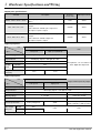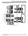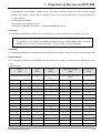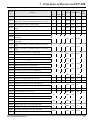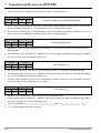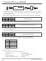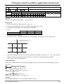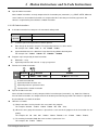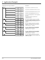
1
DVP-PM APPLICATION MANUAL
Table of Contents
Chapter 1: Program Structure of DVP-PM
1.1
O100 Main Program ........................................................................... 1-1
1.1.1 Manual Motion in O100 Main Program ........................................................ 1-2
1.2
Structure of OX Motion Subroutine ...................................................... 1-2
1.3
Structure of Pn Subroutine ................................................................. 1-4
1.4
Structure of O100, OX and Pn Program Design .................................... 1-6
1.4.1 The Program Structure …………………………………………………………………1-6
Chapter 2: Hardware Specifications and Wiring
2.1
Hardware Specifications ..................................................................... 2-1
2.1.1 Power Specifications .................................................................................. 2-1
2.1.2 I/O Point Specifications .............................................................................. 2-1
2.1.3 Dimension ................................................................................................. 2-3
2.2
Installation & Wiring ........................................................................... 2-4
2.2.1 W iring ....................................................................................................... 2-5
2.2.2 Power Input W iring .................................................................................... 2-5
2.2.3 Safety W iring ............................................................................................. 2-6
2.2.4 I/O Point W iring ......................................................................................... 2-6
2.2.5 W iring with Drives ...................................................................................... 2-10
2.3
Communication Ports ......................................................................... 2-15
2.3.1 COM1 (RS-232) ......................................................................................... 2-15
2.3.2 COM2 (RS-485) ......................................................................................... 2-15
Chapter 3: Functions of Devices in DVP-PM
3.1
Device in DVP-PM ............................................................................. 3-1
3.2
Values, Constants [K]/[H], Floating Points [F] ....................................... 3-4
3.3
Numbering and Functions of External Input/Output Contacts [X]/[Y]....... 3-6
3.4
Numbering and Functions of Auxiliary Relays [M] ................................. 3-7
3.5
Numbering and Functions of Step Relays [S] ....................................... 3-8
3.6
Numbering and Functions of Timers [T] ............................................... 3-8
3.7
Numbering and Functions of Counters [C] ........................................... 3-9
3.8
Numbering and Functions of Registers [D]] .......................................... 3-11
3.8.1 Data Register [D] ....................................................................................... 3-11
3.8.2 Index Registers [V], [Z] .............................................................................. 3-12
3.9
Pointer [N], Pointer [P n ] ...................................................................... 3-13
3.10 Special Auxiliary Relays [M], Special Data Register [D] .......................... 3-13
3.11 Functions of Special Auxiliary Relays and Special Registers .................. 3-22
3.12 Special Registers for Manual Motion Mode ........................................... 3-32
3.12.1 Functions of Special Registers for Manual Motion Mode............................. 3-33
3.12.2 Manual Modes ......................................................................................... 3-48
3.12.3 Application Position & Speed Control Registers for Manual Modes ............. 3-49
Chapter 4: Basic Instructions
4.1
Basic Instructions .............................................................................. 4-1
4.2
Explanations of Basic Instructions....................................................... 4-2
Chapter 5: Categories and Use of Basic Application Instructions
5.1
List of Instructions ............................................................................. 5-1
5.2
Composition of Application Instruction ................................................. 5-3
5.3
Handling of Numeric Values ................................................................ 5-5
5.4
V, Z Index Register Modification ......................................................... 5-8
5.5
Instruction Index ................................................................................ 5-9
5.6
Application Instructions ...................................................................... 5-12
●
(API 00 ~ 09)
Loop Control ................................................................ 5-12
●
(API 10 ~ 19)
Transmission Comparison ............................................. 5-19
●
(API 20 ~ 29)
Four Arithmetic Operation ............................................. 5-24
●
(API 40 ~ 49)
Data Processing ........................................................... 5-37
●
(API 70 ~ 79)
Display of External Settings .......................................... 5-40
●
(API 100 ~ 109)
Communication ............................................................ 5-44
●
(API 110 ~ 138)
Floating Point Operation ............................................... 5-53
●
(API 215 ~ 223)
Contact Type Logic Operation Instruction ...................... 5-80
●
(API 250 ~ 260)
New Instructions ........................................................... 5-86
Chapter 6: Motion Instructions and G-Code Instructions
6.1
List of Motion Instructions and G-Code Instructions.............................. 6-1
6.2
Composition of Motion Instructions and G-Code Instructions ................. 6-2
6.2.1 Motion Instructions
6.2.2 G-Code Instructions ……………………………………………………………….. 6-3
6.3
Motion Instructions .......................................................................... 6-5
●
6.4
(MON 00 ~ 19)
Motion Instructions ..................................................... 6-5
G-Code Instructions ......................................................................... 6-30
●
(G0 ~ 4, 90 ~ 91)
G-Code Instructions.................................................... 6-30
Chapter 7: Use DVP-PM As Slave
7.1
How to Connect DVP-EH2, DVP-PM (as Master) and DVP-PM (as Slave) 7-1
7.1.1 The Structure ............................................................................................. 7-1
7.1.2 Example of Master-Slave Connection .......................................................... 7-1
Chapter 8: Application Examples
8.1
Draw the Trajectories Below by Using Motion Instructions and G-Codes 8-1
8.1.1 Design Procedure ...................................................................................... 8-3
8.2
Applying “motionSample” in PMSoft ............................................................... 8-7
8.2.1 Design Plan ............................................................................................... 8-7
8.2.2 Design Example Program ........................................................................... 8-8
8.3
Planning Variable Speed Operation ................................................................ 8-10
8.3.1 Design Plan ............................................................................................... 8-10
8.3.2 Design Example Program …………………………………………………………….. 8-12
Chapter 9: Appendix
9.1
Appendix A: Special Registers for Manual Motion Mode ........................ 9-1
9.2
Appendix B: Motion Instructions & G-Code Instructions ........................ 9-3
9.3
Appendix C: Error Codes .................................................................... 9-4
1
Program Structure of DVP-PM
Delta’s DVP-PM series MPU is a high-speed positioning and multi-functional programmable logic controller with
2-axis linear/arc interpolation, featuring functions as basic instructions, application instruction, motion instructions
and G-code instructions, making the editing and compiling of program more diverse.
This chapter will introduce the program structure of DVP-PM series MPU. DVP-PM combines the sequential
control and 2-axis interpolation positioning control; therefore, the program is in three types: O100 main program, OX
motion subroutine and Pn subroutine, which will be illustrated in this chapter.
The basic instructions, application instructions and G-Code instructions will be given in Chapter 4 ~ 6.
1.1
O100 Main Program
O100 main program is the PLC sequential control program, which is the main program of sequential control for
DVP-PM series MPU. The O100 main program section only supports basic instructions and application instructions.
Besides processing I/O signals and calling Pn subroutine, basic instructions and application instructions also control
100 OX motion subroutines which enable OX0 ~ OX99. Therefore, O100 main program establishes the main control
program, and the main control program sets up and activates motion subroutines. This is the control structure of the
operation of DVP-PM. See below the operation procedure and features of O100 main program.
1. There are two ways to activate O100 main program
When DVP-PM is powered, and the AUTO/MANU switch goes from MANU to AUTO, M1072 will be
On automatically, and O100 main program will be in RUN status.
When DVP-PM is powered, you can set M1072 to be On or O100 main program to be in RUN status
by communication.
Auto/Manual
C ommunication
M1072
OR
O1 00
Ru n
2. The program is scanned in cycles. When O100 main program is enabled, the scan will starts at the start
flag of O100. When the scan reaches M102 (main program ends instruction), it will return to the start flag of
O100 and resume the scan, as shown in the figure below: The instruction can be compiled in any forms
when Auto/Manual is in the main control program section, i.e. the “sequential control program area"
O100
.
.
.
M102
Main program start flag
Cyclic scan
Sequential control program area
Main program ends instruction
3. There are three ways to stop the operation of O100 main program:
When DVP-PM is powered, and the AUTO/MANU switch goes from AUTO to MANU, M1072 will be
Off automatically, and O100 main program will be in STOP status. The operation of OX and Pn
subroutines will stop at this moment.
When DVP-PM is powered, you can set M1072 to be Off or O100 main program to be in STOP
DVP-PM Application Manual
1-1
1
Program Structure of DVP-PM
status by communication. The operation of OX and Pn subroutines will stop immediately.
When errors occur during the design, compiling or operation of the program, O100 main program will
stop automatically. See 3.13 for the table of the error codes and their causes.
4. O100 main program supports basic instructions and application instructions; therefore, you can design the
program according to your actual needs. Besides, you can further activate OX0 ~ OX99 motion subroutines
by setting up the parameters in motion instructions and the activation No. in the motion program.
O100 main program does not support motion instructions and G-Code instructions; therefore, please
design motion instructions and G-Code instructions in OX0 ~ OX99 motion subroutines. See 1.2 for
more details.
O100 main program is able to call Pn subroutine. See 1.3 for more details.
5. The above explanations are sorted in the table below:
O100 main program
Explanation
Start of the program
Start flag of O100 main program (*In ladder diagram editing mode, it will be set up
automatically. Therefore you do not have to compile this row.)
End of the program
End of M102 main program (*In ladder diagram editing mode, it will be set up
automatically. Therefore you do not have to compile this row.)
1. DVP-PM MANU → AUTO
Execution of the
program
2. M1072 Off → On by communication
How to operate
Scan and operation in cycles
Instruction supported
Quantity
Basic instructions and application instructions
Only one O100 program is allowed in the program
1. A PLC sequential control program
Features & functions
2. Able to activate OX0 ~ OX99 motion subroutines and call Pn subroutine
3. The three sequences can be piled freely when used with OX0 ~ OX99 motion
subroutines and Pn subroutines.
6. Manual Motion in O100 Main Program
In O100 main program, you can use special registers for designing your own manual motion modes (see
3.12 for how to set it up).
1.2
Structure of OX Motion Subroutine
OX0 ~ OX99 motion subroutines are motion control programs for controlling the motions on X and Y axes in
DVP-PM. The OX0 ~ OX99 motion subroutine sections support basic instruction, application instructions, motion
instructions and G-Code instructions, and they are able to call Pn subroutines. OX0 ~ OX99 are for the user to
design and compile the moving path of X and Y axes. See below the operation procedure and features of OX
motion subroutines.
1. How to activate OX0 ~ OX99 motion subroutines:
1-2
When O100 main program is in RUN status, you can set up the execution No. of OX in O100 main
DVP-PM Application Manual
1
Program Structure of DVP-PM
program (D1868: K0 ~ K99) and set b12 of X-Y axis operation instruction (D1846) to be On to
enable OX motion subroutine.
When you enable OX motion subroutine, please make sure there are no other motion subroutines in
operation.
O100
D1846
AND
Oxn'
O Xn
Run
in oper ation
2. The scan starts whenever the program is enabled. When O100 main program activates OX motion
subroutine, the scan will start from the start flag of OX motion subroutine and end at M2 (motion
.
.
.
Cyclic scan
Ma in co ntro l p ro gra m s e ction
subroutine ends instruction), i.e. the end of the motion subroutine, as shown in the figure below:
X0
MOV
H800A D1868
OUT
M1074
Set O X as O X 10
Set X0 = On to enable O X 10 moti on subroutine
.
.
.
OX 10
Execute
once
Moti on s ubr outi ng
secti on
X0 On
Start flag of motion subr outine
.
.
.
M2
Motion subr outine ends instr uction
When X0 = On, OX10 motion subroutine will be enabled and stop when the execution reaches M2 (motion
subroutine ends instruction). The execution will only execute once. If you need a re-execution, re-activate
X0 to re-enable OX10 motion subroutine.
3. There are four ways to stop OX motion subroutine:
When DVP-PM is powered, and the AUTO/MANU switch goes from AUTO to MANU, M1072 will be
Off automatically, and O100 main program will be in STOP status. The operation of OX motion
subroutines will stop at this moment.
You can also stop OX by controlling the input signals of the external control terminal (STOP0).
When DVP-PM is powered, you can also stop OX by setting D1846 to be 0 through communication.
When errors occur during the design, compiling or operation of the motion subroutine, OX will stop
automatically. See 3.13 for the table of the error codes and their causes.
DVP-PM Application Manual
1-3
1
Program Structure of DVP-PM
4. OX motion subroutines support basic instructions, application instructions, motion subroutines and G-Code
subroutines. Therefore, you can design your own motion program by using these instructions and setting
up X-Y axis parameters for your desired X-Y motion control.
The instructions mentioned above shall be designed in OX0 ~ OX99 motion subroutines.
OX motion subroutine supports calling Pn subroutine. See 1.3 for more details.
5. The above explanations are sorted in the table below:
OX motion subroutine
Explanation
Start of the program
OX motion subroutine (OX0 ~ OX99, 100 motion subroutines)
End of the program
M2 motion subroutine ends
1. When O100 main program is in RUN statues, set D1846_b12 as 1 to enable OX
motion subroutine.
Execution of the
program
2. When O100 main program is in RUN status, set D1846_b12 by communication to
also enable OX motion subroutine.
3. Stop OX motion subroutine by the input signals at external control terminal (STOP0).
Note: When you need to enable OX motion subroutine, make sure there are no other
motion subroutines in operation.
How to operate
Execute once whenever the subroutine is enabled. Re-enable it for the re-execution.
Basic instructions, application instructions, motion instructions, and G-Code instructions.
Instruction supported
Quantity
Note: Avoid pulse-type instruction when using basic instructions and application
instructions.
The program can only contain 100 OX motion subroutines. If you need to active other OX
motion subroutines, you can set up D1868 and enable the subroutine (SET M1074).
1. A motion subroutine which can only be enabled by designing O100 main program.
2. Offers the third axis (Z) control. See 6.4 G00 and G01 instructions for more details.
Features & functions
3. Can be enabled/ disabled by controlling the external terminals, program design and
communication.
4. Able to call Pn subroutine.
5. The three sequences can be piled freely when used with O100 main program and Pn
subroutines.
1.3
Structure of Pn Subroutine
Pn subroutine is a general-purpose subroutine for calling subroutines by O100 main program and OX motion
subroutines. When Pn subroutine is called in O100 main program, the Pn subroutine area will support basic
instructions and application instructions. When Pn subroutines is called in OX0 ~ OX99 motion subroutines, the Pn
subroutine area will support basic instructions, application instructions, motion instructions and G-Code instructions.
The Pn subroutine is called in O100 or OX, O100 or OX will jump to Pn subroutine when Pn subroutine is being
executed and return to the next row after Pn subroutine to resume the execution when SRET is executed.
1. How to enable Pn subroutine:
1-4
Call Pn subroutine in O100 main program.
Call Pn subroutine in OX motion subroutine.
DVP-PM Application Manual
1
Program Structure of DVP-PM
2. How does the scan work: The scan executes once whenever Pn subroutine is called once. After Pn
subroutine is called in O100, Pn subroutine will be executed, and the subroutine will end when the
execution reaches SRET (subroutine ends instruction). The program will return to the next row after Pn and
M1 00 0
C ycl ic scan
CALL
O1 00 a nd O X 10
prog ram bifu rcat ion p oint
P0
Call P 0 subroutine
X0
b
MOV
H800A D1868
OUT
M1074
Set O X as O X 10
When X 0 = On, O X 10 motion s ubr outine will be enabl e.
Path a will be tr ue.
.
.
Exec ute onc e
.
OX 10
Start flag of motion subroutine
.
.
M1000
.
CALL
P2
Call P 2 subroutine
.
.
.
Exec ute onc e
Exec ute onc e
a
M2
Motion subr outine ends instr uc ti on
P2
P2 subroutine
.
.
.
SRET
Exec ute onc e
Sub rou tine
s ec tion
Sub rou tine
s ec tion
Motio n sub ro utine
s ec tion
Ma in co ntro l p rog ra m s e ction
resume the scan. The same operation also applied to OX motion subroutine calling Pn subroutine.
P0
Subroutine ends instruction
P0 subroutine
.
.
.
SRET
Subroutine ends instruction
In P0 subroutine section, you can compile basic instructions and application instructions freely, and in P2
subroutine section, you can compile basic instructions, application instructions, motion instructions and
G-Code instructions freely.
3. There are three ways to stop Pn subroutine:
When DVP-PM is powered, and the AUTO/MANU switch goes from AUTO to MANU, M1072 will be
Off automatically, and O100 main program will be in STOP status. The operation of OX motion
subroutines and Pn subroutine will stop at this moment.
When DVP-PM is powered, you can also stop OX by setting D1846 to be 0 through communication.
DVP-PM Application Manual
1-5
1
Program Structure of DVP-PM
When errors occur during the operation of Pn subroutine, Pn will stop automatically. See 3.13 for the
table of the error codes and their causes.
4. When Pn subroutine is called in O100 main program, the Pn subroutine will only support basic instructions
and application instructions. When Pn subroutines is called in OX0 ~ OX99 motion subroutines, the Pn
subroutine will support basic instructions, application instructions, motion instructions and G-Code
instructions.
5. The above explanations are sorted in the table below:
Pn subroutine
Explanation
Start of the program
Start flag of Pn subroutine (P0 ~ P255)
End of the program
End of SRET subroutine
Execution of the
program
1. Call Pn subroutine in O100 main program.
How to operate
Execute once whenever the subroutine is enabled. Re-enable it for the re-execution.
2. Call Pn subroutine in OX motion subroutine.
1. When called in O100: supports basic instructions and application instructions
Instructions supported
2. When called in OX: supports basic instructions, application instructions, motion
instructions and G-Code instructions.
Note: When you need to call Pn in OX and use basic instructions and application
instructions, please avoid pulse-type instructions.
Quantity
The program can only contain 256 Pn subroutines.
1. A general-purpose subroutine
Features & functions
1.4
2. For O100 main program and OX motion subroutine to call a subroutine.
3. The three sequences can be piled freely when used with O100 main program and
OX motion subroutine.
Structure of O100, OX and Pn Program Design
O100 main program, OX motion subroutine and Pn subroutine are introduced in 1.1 ~ 1.3. In this section, we
will further illustrate how to mix the structures of the three and how to design it.
1.4.1 The Program Structure
Assume we would like to design a O100 main program, OX0 motion subroutine, P1 subroutine and P2
subroutine (5 program sections), please follow the design procedure as the follow:
1-6
DVP-PM Application Manual
1
Program Structure of DVP-PM
O100 main program
.
.
.
Call OX0
.
.
.
.
.
.
.
Call P2
.
.
.
M102
.
.
.
Call P1
.
.
.
P1 subroutine
.
.
.
Call OX3
.
.
.
OX3 motion subroutine
OX0 motion subroutine
.
.
.
SRET
M2
P2 subroutine
SRET
M2
.
.
.
Mot io n sub rou ti ne
se ctio n
To explain the example in an easier way, the program design will be given in section (1) ~ (5), as shown below:
.
OX0
Sta rt f la g of O X 0 mo tio n su bro uti ne
C ALL
P1
.
.
M1 00 0
C al l P1 su bro uti ne
(1)
.
.
.
M2
Mo tio n su bro uti ne en ds i nstru ct io n
.
.
Ma in con trol p rog ram
se ctio n
.
MOV H 80 00 D 18 68 Se t O X a s O X 0
SET M1 07 4 En ab le O X 0 mo tio n su bro uti ne
.
(2)
.
.
M1 00 0
C ALL
P2
C al l P2 su bro uti ne
.
.
.
Sub rou ti ne
se ctio n
P1
P1 su bro uti n e
.
.
(3)
.
SR ET Mo tio n su bro uti ne en ds i nstru ct io n
Moti on
sub rou ti ne
se ctio n
OX3
Sta rt f la g of O X 3 mo tio n su bro uti ne
.
(4)
.
.
M2
.
P0
Mo tio n i nstru ct io n e nd s i nstru ctio n
P0 su bro uti n e
Sub rou ti ne
se ctio n
.
.
MOV H 80 03 D 18 68 Se t O X a s O X 3
(5)
.
SET
M1 07 4 En ab le O X 3 mo tio n su bro uti ne
.
.
SR ET Mo tio n su bro uti ne en ds i nstru ct io n
DVP-PM Application Manual
1-7
1
Program Structure of DVP-PM
Explanations on the program design:
1.
The compiling sequence is from (1) to (5), but there is not a rule for the sequence of how and where you
place them.
2.
There can only be one O100 main program (2), and it cannot be called by other programs. O100 can call
OX motion subroutines and Pn subroutines.
3.
OX motion subroutine can be called by O100 main program and Pn subroutine, and it can also call a Pn
subroutine.
4.
Pn subroutine can be called by O100 main program and OX motion subroutine, and it can also call a OX
motion subroutine.
Note:
1.
More then two OX motion subroutines cannot be executed at the same time. Therefore, when OX0
motion subroutine is executed, OX3 will not be able to work, and vice versa.
2.
Once O100 main program or Pn subroutine enables an OX motion subroutine, it will continue to execute
the next row of the program without paying attention to the OX motion subroutine.
3.
The enabled OX motion subroutine will only execute once. If you want it to execute again, you have to
re-enable it.
Instructions supported in each program section: (O: supported; X: not supported)
Section
O100 main program
OX motion subroutine
(OX0, OX3)
P1 subroutine
P2 subroutine
Basic instruction
O
O
O
O
Application
instruction
O
O
O
O
Motion instruction
X
O
O
X
G-Code instruction
X
O
O
X
Instructions supported
are fixed
Called by OX motion
subroutine; therefore,
motion instructions
and G-Code
instructions are
supported.
Called by O100 main
program; therefore,
motion instructions
and G-Code
instructions are not
supported.
Explanation
Instructions supported
are fixed
Remarks:
Main program
Subroutine
Motion subroutine
Start of the program
-
Pn (n = 0 ~ 255)
OXn (n = 0 ~ 99)
End of the program
-
SRET
M2
No limitation
No limitation
No limitation
Execution of the
program
RUN normally
Called by main program or motion
subroutine
Called by main program or
subroutine
How to operate
In cycles
Execute once whenever being
called once
Execute once whenever being
called once
1
256, depending on the user’s
demand.
100, depending on the user’s
demand.
Placing sequence
Quantity
1-8
DVP-PM Application Manual
2
Hardware Specifications and Wiring
2.1 Hardware Specifications
This chapter only provides information on electrical specification and wiring. For detailed information on program
design and instructions, please refer to Chapter 5 ~ 6. For how to purchase its peripheral devices, please refer to the
instruction sheet enclosed with the product.
2.1.1 Power Specifications
Item
(
)
Description
Power supply voltage
100 ~ 240V AC -15% ~ 10% , 50/60Hz ± 5%
Fuse capacity
2A/250V AC
Power consumption
60VA
DC24V current supply
500mA
Power protection
DC24V; output short-circuited
Withstand voltage
1,500V AC (Primary-secondary); 1,500V AC (Primary-PE); 500V AC (Secondary-PE)
Insulation impedance
> 5MΩ (all I/O point-to-ground: 500V DC)
Noise immunity
ESD: 8KV Air Discharge; EFT: Power Line: 2KV, Digital I/O: 1KV, Analog & Communication I/O: 250V
Earth
The diameter of grounding wire shall not be less that of L, N terminal of the power. When many PLCs
are in use at the same time, please make sure every PLC is properly grounded.
Operation/storage
Operation: 0°C ~ 55°C (temperature), 50 ~ 95% (humidity), pollution degree 2
Storage: -25°C ~ 70°C (temperature), 5 ~ 95% (humidity)
Vibration/shock
immunity
International standards: IEC61131-2, IEC 68-2-6 (TEST Fc)/IEC61131-2 & IEC 68-2-27 (TEST Ea)
Weigh (approx. g.)
478/688
2.1.2 I/O Point Specifications
Input point specifications:
Terminal
Description
Response
characteristics
Max. input current
START0, START1
Enabling input
10ms
6mA
STOP0, STOP1
Disabling input
10ms
6mA
Right limit input/left limit input
10ms
6mA
LSP0/LSN0, LSP1/LSN1
A0+, A0-, A1+, A1-
MPG A-phase pulse input +, - (differential signal input)
200KHz
15mA
B0+, B0-, B1+, B1-
MPG B-phase pulse input +, - (differential signal input)
200KHz
15mA
1ms
15mA
1ms
10mA
PG0+, PG0-, PG1+, PG1-
Zero point signal input +, - (differential signal input)
There are two variations according to different operation
modes:
DOG0, DOG1
1. DOG signal when zero return
2. Inserting enabling signal at 1-segment speed or
2-segment speed
DVP-PM Application Manual
2-1
2
Hardware Specifications and Wiring
Output point specifications:
Terminal
CLR0+, CLR0-, CLR1+, CLR1-
Description
Clearing signals (by the error counter in servo
drive)
Response
characteristics
Max. input current
10ms
20mA
500KHz
40mA
500KHz
40mA
Forward/reverse running mode: Forward pulse
output
FP0+, FP0-, FP1+, FP1-
Pulse direction: Towards pulse output end
A, B phase: A-phase output
Forward/reverse running mode: Reverse pulse
output
RP0+, RP0-, RP1+, RP1-
Pulse direction: Towards output end
A, B phase: B-phase output
Digital input points:
Item
24V DC single common port input
Note
Low speed
Spec
Input wiring type
High speed (200KHz)
Change wiring from S/S to SINK or SOURCE
Input indicator
LED display; light on = ON, light off = OFF
Input voltage
-
Action
level
OffOn
20us
OnOff
30us
Response time/noise
immunity
Input point X0 ~ X7 can conduct 10
~ 60ms digital filter adjustment.
10ms
0.5us
Digital output point:
Item
Single common port transistor output
Single common port relay output
Spec
Maximum frequency
Low speed
High speed
10KHz
200KHz
Output indicator
LED display; light on = ON, light off = OFF
Minimum load
-
2mA/DC power supply
5 ~ 30V DC
< 250V AC, 30V DC
Photocoupler isolation
Electromagnetic isolation
Working voltage
Isolation
Current specification
Max. output
delay time
2-2
0.3A/1 point@ 40°C
OffOn
20us
OnOff
30us
30mA
0.2us
Over-current protection
For load ON/OFF control
2A/1 point (5A/COM)
75VA (conductive), 90W (resistive)
10ms
N/A
DVP-PM Application Manual
2
Hardware Specifications and Wiring
80
90
2.1.3 Dimension
164
82.2
174
(Unit: mm)
Product Profile & Outline:
3
2
4
1 Communication port cover
5
2 I/O terminal cover
6
1
3 Function card/memory card cover
4 I/O terminals
7
5 I/O terminal No.
8
6 Extension module connection port cover
10
7 Input indicator
8 Output indicator
5
9
4
9 DIN rail clip
9
DIN rail (35mm)
1 Mounting screw
6
2
2 Direct mounting hole
1
7
4 Function card mounting hole
8
7
3 Battery socket
1
5 Memory card port
6 POWER/BAT.LOW/ERROR indicator
3
4
5
2
7 Extension module connection port
8 Function card port
Open COM1 cover
DVP-PM Application Manual
Open COM2 cover
2-3
2
Hardware Specifications and Wiring
The battery shall be changed within 1 minute.
Remove RS-485 terminal
Removable Terminal Block
COM 2 (RS-485)
MANU / AUTO switch
COM 1 (RS-232)
Battery
Part
Description
COM2 (RS-485)
For both master and slave modes
MANU/AUTO switch
RUN/STOP control
COM1 (RS-232)
Slave mode (can be used with COM2 at the same time)
Wiring Terminals: See 2.1.1 for detailed specifications.
24G
+24V
S/S0
STOP0
START0 DOG0
LSP0
LSN0
PG0-
S/S1
STOP1
LSP1
PG0+ START1 DOG1 LSN1
PG1-
PG1+
X0
S/S2
X2
X1
X4
X3
X6
X5
X7
DVP-20PM
( AC Power IN, DC Signal IN )
A0+
B0+
A0-
A1+
B0-
B1+
A1-
CLR0+ CLR1+
B1-
CLR0-
FP0+
CLR1-
RP0+
FP0-
FP1+
RP0-
RP1+
FP1-
RP1-
Y0
Y1
C0
Y2
C1
Y3
C2
Y4
C3
Y6
Y5
Y7
2.2 Installation & Wiring
DVP-PM is and OPEN-TYPE device and therefore should be installed in an enclosure free of airborne dust,
humidity, electric shock and vibration. The enclosure should prevent non-maintenance staff from operating the device
(e.g. key or specific tools are required for opening the enclosure) in case danger and damage on the device may
occur.
DO NOT connect input AC power supply to any of the I/O terminals; otherwise serious damage may occur. Check
all the wiring again before switching on the power. Make sure the ground terminal
is correctly grounded in order
to prevent electromagnetic interferences.
2-4
DVP-PM Application Manual
2
Hardware Specifications and Wiring
2.2.1 Wiring
How to install DIN rail:
DVP-PM can be secured to a cabinet by using the DIN rail of 35mm in height and
7.5mm in depth. When mounting PLC to DIN rail, be sure to use the end bracket to
stop any side-to-side movement of PLC and reduce the chance of wires being
loosen. A small retaining clip is at the bottom of PLC. To secure DVP-PM to DIN rail,
place the clip onto the rail and gently push it up. To remove it, pull the retaining clip
down and gently remove DVP-PM from the DIN rail, shown in the figure.
1. How to screw: Please use M4 screws which fit the dimension of
> 50mm
the product.
DVP MPU
2. Please install DVP-PM in an enclosure with sufficient space
> 50mm
> 50mm
> 50mm
around it to allow heat dissipation, as shown in the figure.
Wiring notes:
1. Use O-type or Y-type terminal. See the figure in the right for its
specification. PLC terminal screws should be tightened to 5 ~ 8 kg-cm
(4.3 ~ 6.9 in-Ibs).
Below 6.2
2. DO NOT wire empty terminal
To suit M3.5 screw terminals
•
. DO NOT place the input signal
cable and output power cable in the same wiring circuit.
3. DO NOT drop tiny metallic conductor into the PLC while screwing and
Below 6.2
wiring. Tear off the sticker on the heat dissipation hole for preventing
alien substances from dropping in, to ensure normal heat dissipation of
the PLC.
4. Use 60/75ºC copper conductor only.
2.2.2 Power Input Wiring
The power input of DVP-PM series is AC. When operating it, please make sure that:
1. The input voltage should be current and its range should be 100 ~ 240V AC. The power should be connected to L
and N terminals. Wiring AC110V or AC220V to +24V terminal or input terminal will result in serious damage on
the PLC.
2. The AC power input for PLC MPU and I/O extension modules should be On or Off at the same time.
3. Use wires of 1.6mm (or longer) for the grounding of PLC MPU.
4. The power shutdown of less than 10ms will not affect the operation of DVP-PM. However, power shutdown time
that is too long or the drop of power voltage will stop the operation of DVP-PM and all outputs will go “Off". When
the power supply turns normal again, DVP-PM will automatically return to its operation. Please be aware of the
latched auxiliary relays and registers inside DVP-PM when programming.
DVP-PM Application Manual
2-5
2
Hardware Specifications and Wiring
AC power input:
100~240VAC
L
N
+24V 24G
S/S
X0
X1
X2
2.0 A
DC/DC
+5V
0.5A is the maximum power supply for +24V power supply output terminal. DO NOT connect other external power
supplies to this terminal. Every input terminal requires 6 ~ 7mA to be driven; e.g. the 16-point input will require
approximately 100mA. Therefore, +24V cannot give output to external load that is more than 400mA.
2.2.3 Safety Wiring
Since DVP-PM controls many devices, actions of any device may affect actions of other devices and the breakdown
of any one device may cause the breakdown of the entire auto-control system and danger. Therefore, we suggest you
wire a protection circuit at the power input terminal, as shown in the figure below.
5
MC
1
4
AC power supply load
Power circuit protection fuse (3A)
Power indicator
Emergency stop
8
2
Guard
Limit
3
MC
System circuit isolation device
MC
1
L
7
N
This button can cut off the system power supply when
accidental emergency takes place.
6
The device is made of electromagnetic contactor and
relay as the switch to prevent the instability of system
when the power is intermittently supplied.
DVP-PLC (main processing unit)
Earth
Power supply: AC: 100 ~ 240V AC, 50/60Hz
2.2.4 I/O Point Wiring
There are two types of DC input, SINK and SOURCE.
(DC Signal IN)
S/S
Sinking
X0
SINK mode: Common port for current input S/S
2-6
DVP-PM Application Manual
2
Hardware Specifications and Wiring
Input point loop equivalent circuit:
SINK
+24V
24VDC
+5V
24G
S/S
X0
Wiring loop:
+24V 24G
S/S X0 X1 X2
Sink Type
(DC Signal IN)
X0
S/S
Sourcing
Source mode: Common port for current output S/S
Input point loop equivalent circuit:
SOURCE
+24V
24VDC
+5V
24G
S/S
X0
Wiring loop:
+24V 24G
S/S X0
X1
X2
Source Type
DVP-PM Application Manual
2-7
2
Hardware Specifications and Wiring
Wiring of differential input:
A0 ~ A1 and B0 ~ B1 of DVP-PM are all high-speed input circuit, and others are DC24V input. The working frequency
of high-speed input circuit can reach up to 200KHz and is mainly for connecting to differential (double-wire) LINE
DRIVER output circuit.
Wiring in a high-speed, high-noise environment
DVP20PM00D high-speed input
Encoder output
A+
A0+
A-
A0 -
A
Twisted pair
cable
Differential output
A+
B0+
B-
B0 -
B
Wiring of DVP20PM00D DC5V SINK
PG0+
(5V SINK)
+
5~24V
PG0 -
NPN
SENSOR
Wiring of DVP20PM00D DC5V SOURCE
PNP
SENSOR
+
5~24V
PG0+
(5V SOURCE)
PG0 -
Relay (R) contact circuit wiring
DVP-**-**-**-R
2
LOAD
Y0
LED
3
POWER
RY
C0
C2 Y2 C3
5
C4 ~ C7 Y4 Y5 Y6 Y7
Y3
8
1
3
2
7
MC2
MC1
9
6
RELAY OUTPUT
Flywheel diode: To extend the lift span of contact
4
Emergency stop: Uses external switch
Fuse: Uses 5 ~ 10A fuse at the shared terminal of output contacts to protect the output circuit
2-8
DVP-PM Application Manual
2
Hardware Specifications and Wiring
Varistor: To reduce the interference on AC load
DC power supply
Neon indicator
AC power supply
Incandescent light (resistive load
Manually exclusive output: Uses external circuit and forms an interlock, together with PLC internal program, to
ensure safe protection in case of any unexpected errors.
Transistor (T) contact circuit wiring
5
5
C0 Y0 C1 Y1 C3 Y4 Y5 Y6
DVP-**-**-**-T
LOAD
MC1
Y7
M C2
Y0
< 0.5A
LED
4
1
C0
4
2
3
TRANSISTOR OUTPUT
3
DC power supply
Emergency stop
Circuit protection fuse
Flywheel diode + inductive load
Manually exclusive output: Uses external circuit and forms an interlock, together with PLC internal program, to
ensure safe protection in case of any unexpected errors.
Wiring of differential output
DVP20PM00D
Drive
A+
FP+
FP
A-
FP-
Twisted pair
cable
FG
RP+
B+
RP-
B-
RP
DVP-PM Application Manual
Photocoupler
Input example
Line Receiver
Input example
2-9
2
Hardware Specifications and Wiring
2.2.5 Wiring with Drives
DVP-PM and Delta ASD-A series servo drive:
+24VDC input
Delta servo drive
ASD-A series
START0
24V
VDD
STOP0
0V
COM+
FP 0+
PLS
FP 0-
/PLS
RP 0+
SIGN
RP 0-
/SIGN
LSP1
CLR0+
DI2
LSN1
CLR0-
24V
LSP0
LSN0
+24V
START1
STOP1
COM5-24VDC
+24V
MPG pulses
Delta servo drive
Shielded cable
ASD-A series
A0+
A phase
A0-
VDD
B0+
COM+
B phase
24V
B0-
MPG pulses
FP 1+
PLS
FP 1-
/PLS
RP 1+
SIGN
RP 1-
/SIGN
CLR1+
DI2
Shielded cable
A1+
A phase
A1B1+
B phase
B1-
COM-
CLR1PG 0+
5-24VDC
PG 0 5-24VDC
PG 1+
PG 15-24VDC
2-10
DVP-PM Application Manual
2
Hardware Specifications and Wiring
DVP-PM and Panasonic CN5 series servo drive:
+2 4VD C i np ut Pa na son ic servo drive
C N 5 serie s
START0
2 4V
S TO P0
0V
L SP 0
L SN0
FP 0 +
P ULS 1
3
DOG0
FP 0 -
P ULS 2
4
S/S0
RP 0 +
SIGN1
5
RP 0 -
S IGN2
6
+24 V
S TART1
S TO P1
+24 V
L SP1
CL R0+
L SN1
CL R0-
DOG1
5 -2 4V DC
S/S1
MPG p ul ses
Pa na son ic servo drive
S hi elde d ca bl e
C N5 serie s
A 0+
A p ha se
A 0B 0+
B ph a se
B 0-
MPG p ul ses
Shielde d ca bl e
FP 1 +
P ULS 1
3
FP 1 -
P ULS 2
4
RP 1 +
SIGN1
5
RP 1 -
S IGN2
6
A 1+
A p ha se
A 1B 1+
B ph a se
B 1-
CL R1+
CL R1-
PG 0+
PG 0 -
5 -2 4VDC
5 -2 4VDC
PG 1+
PG 15 -2 4VDC
DVP-PM Application Manual
2-11
2
Hardware Specifications and Wiring
DVP-PM and Yaskawa servo drive:
+2 4VD C i np ut
S TART0
2 4V
S TO P0
0V
Ya ska w a servo drive
L SP 0
L SN0
FP 0 +
PULS
7
DOG0
FP 0 -
/P ULS
8
S/S0
RP 0 +
S IGN
11
RP 0 -
/S IGN
12
L SP1
CL R0+
CL R
15
L SN1
CL R0-
/CL R
14
+24 V
S TART1
S TO P1
+24 V
DOG1
5 -2 4V DC
S/S1
MPG p ul ses
Ya ska w a servo drive
Shielde d ca bl e
A 0+
A p ha se
A 0B 0+
B ph ase
B 0-
MPG p ul ses
Shielde d ca bl e
7
FP 1 +
PULS
FP 1 -
/P ULS
8
RP 1 +
S IGN
11
RP 1 -
/S IGN
12
CL R1+
CL R
15
CL R1-
/CL R
14
A 1+
A p ha se
A 1B 1+
B ph ase
B 1-
PG 0+
PG 0 -
5 -2 4V DC
5 -2 4V DC
PG 1 +
PG 15 -2 4V DC
2-12
DVP-PM Application Manual
2
Hardware Specifications and Wiring
DVP-PM and Mitsubishi MJR2 series servo drive:
+2 4VD C i np ut
Mit su b ish i servo d rive
MJR 2 seri es
S TART0
2 4V
S TO P0
0V
L SP 0
L SN0
FP 0 +
PP
3
DOG0
FP 0 -
PG
13
S/S0
RP 0 +
NP
2
RP 0 -
NG
12
CL R0+
CR
8
SG
10
+24 V
S TART1
STO P1
L SP1
L SN1
+24 V
CL R0-
DOG1
5 -2 4V DC
S/S1
MPG p ul ses
Mit su b ish i servo d rive
S hi el de d ca bl e
MJR 2 seri es
A 0+
A p ha se
A 0B 0+
B ph ase
B 0-
MPG p ul ses
S hi el de d ca bl e
FP 1 +
PP
3
FP 1 -
PG
13
RP 1 +
NP
2
RP 1 -
NG
12
CL R1+
CR
8
CL R1-
SG
10
A 1+
A p ha se
A 1B 1+
B ph ase
B 1-
PG 0+
PG 0 -
5 -2 4VDC
5 -2 4V DC
PG 1 +
PG 1 5 -2 4V DC
DVP-PM Application Manual
2-13
2
Hardware Specifications and Wiring
DVP-PM and FUJI servo drive:
+2 4VD C i np ut
S TART0
2 4V
S TO P0
0V
FU JI servo d rive
L SP 0
L SN0
FP 0 +
CA
35
DOG0
FP 0 -
*CA
36
S/S0
RP 0 +
CB
33
RP 0 -
*CB
34
+24 V
S TART1
S TO P1
+24 V
L SP1
CL R0+
L SN1
CL R0-
DOG1
5 -2 4V DC
S/S1
MPG p ul ses
FU JI servo d rive
S hi el de d ca bl e
A 0+
A p ha se
A 0B 0+
B ph ase
B 0-
MPG p ul ses
Shielde d ca bl e
FP 1 +
CA
35
FP 1 -
*CA
36
RP 1 +
CB
33
RP 1 -
*CB
34
A 1+
A p ha se
A 1B 1+
B ph ase
B 1-
CL R1+
CL R1-
PG 0+
PG 0 -
5 -2 4VDC
5 -2 4V DC
PG 1 +
PG 15 -2 4V DC
2-14
DVP-PM Application Manual
2
Hardware Specifications and Wiring
2.3 Communication Ports
DVP-PM has two communication ports, COM1 (RS-232 communication) and COM2 (RS-485 communication).
2.3.1 COM1 (RS-232)
1. The interface of COM1 is RS-232, for uploading and downloading of the program. It supports Modbus
communication format with baud rate 9,600 ~ 115, 200bps.
The communication cable:
TO PC
9
5
6
1
TO 20PM
MINI DIN TERMINAL
9 PIN D-SUB
PC/TP COM Port
9 PIN D-SUB female
Tx
Rx
GND
PM COM1 Port
8 PIN MINI DIN
3
2
5
7
8
1
4
6
4
5
8
1,2
Rx
Tx
G ND
5V
2
5
1
4
8
3
6
7
See the catalog of Delta PLCs for detailed model names or download the most updated information on the
accessories on Delta's website.
2. COM1 is for Slave mode. Therefore, it can be connected to a human machine interface for monitoring purposes.
2.3.2 COM2 (RS-485)
1. The interface of COM2 is RS-485, for the communication among many masters and slaves. It supports Modbus
communication format with baud rate 9,600 ~ 115,200bps.
2. COM2 is for Master or Slave mode. When for Master mode, it can be connected to a Delta PLC or a drive in the
next level (e.g. Delta servo drive, temperature controller, AC motor drive, and so on) for reading/writing data.
When for Slave mode, it can be connected to a human machine interface (e.g. Delta’s TP and DOP series HMI)
for monitoring purposes.
DVP-PM Application Manual
2-15
2
Hardware Specifications and Wiring
MEMO
2-16
DVP-PM Application Manual
3
Functions of Devices in DVP-PM
3.1 Devices in DVP-PM
Function Specifications:
Item
Specification
Note
Number of control axes
2-axis synchronous linear/arc interpolation and independent 2-axis
control
Program storage
Built-in 64K step storage device
Units
Motor system
Combined system
Machine system
How does MPU read/write
extension module
Uses FROM/TO instruction to read/write the contents of CR in the
extension module. If the content is 32-bit, it needs 2 CRs for the
content.
Series connection with MPU
When used as an extension module, the built-in CR0 ~ CR199
(corresponding to its own D1500 ~ D1699) are for the MPU to
read/write.
Pulse output method
3 modes: Pulse/Dir, FP(CW) / RP(CCW), A/B by differential output
Maximum speed
For single axis: 500K PPS
1
For interpolation axis: 500K PPS
Operation switch AUTO/MANU (auto/manual selection), START, STOP
Detector
Input signal
Output signal
DOG (near point), LSP (forward running limit), LSN (reverser running
limit), PG0 (zero point)
General input
point
X0 ~ X7, I/O modules extendable; maximum 256 points extendable
Servo output
FP (forward pulse), RP (reverse pulse), CLR (clear signal)
General output
point
Y0 ~ Y7, I/O modules extendable; maximum 256 points extendable
Series
Program write-in/read-out communication port:
communication
COM1: RS-232/COM2: RS-485 (can be master or slave)
port
Program stored by HPP03
Special
extension
module
Optional
The right-side extension module and DVP-EH2 series share all
Maximum 8 modules
modules, AD, DA, PT, TC, XA, PU (maximum 8 modules extendable). extendable and will
not occupy any I/O
The left side can connect to new high-speed extension modules
points.
(maximum 8).
Basic instruction
27
Application instruction
56
Motion instruction
22
OX0 ~ 99 (Positioning Program):
M02: program stops (END)
M -Code
M00 ~ M01, M03 ~ M99: program pauses (WAIT), for free use
O100 (Sub-task Program):
M102: program stops (END)
G-Code
G0 (fast move), G1 (linear interpolation), G2 (clockwise arc
interpolation), G3 (counter-clockwise arc interpolation), G4 (pause),
G90 (absolute coordinate), G91 (relative coordinate)
Self-diagnosis
Displaying parameter error, program error, external error, and so on.
DVP-PM Application Manual
3-1
3
Functions of Devices in DVP-PM
X
External input relay
Corresponds to
external input points
X0 ~ X377, octal encoding, 256 points
Total 512 points
Y
Relay (bit)
M
T
Corresponds to
external output points
External output relay Y0 ~ Y377, octal encoding, 256 points
Auxiliary
relay
Timer
General
purpose
M0 ~ M499, 500 points (*2)
Latched
M500 ~ M999, 500 points (*3)
Special
purpose
M1000 ~ M2999, 2,000 points (part for latched)
10ms
M3000 ~ M4095, 2,096 points (*3)
T0 ~ T255, 256 points (*2)
Total 4,096 points
The contact can be
On/Off in the program.
Total 256 points
TMR instruction. If the
timing reaches its
target, the T contact of
the same No. will be
On.
Total 256 points
The counter indicated
by CNT (DCNT)
instruction. If the
counting reaches its
target, the C contact
of the same No. will
be On.
Total 1,024 points
The contact can be
On/Off in the program.
16-bit
C0 ~ C99, 100 points (*2)
counting
C100 ~ C199, 100 points (*3)
up
C
Counter
S
Internal
relay
C200 ~ C219, 20 points (*2)
32-bit
counting
up/down C220 ~ C255, 36 points (*3)
General
purpose
S0 ~ S499, 500 points (*2)
Latched
S500 ~ S1023, 524 points (*3)
T
Present value in
timer
C
Present value in
counter
When the timing
reaches its target, the
contact of the timer
will be On.
T0 ~ T255, 256 points
Register (word data)
C0 ~ C199, 16-bit counter, 200 points
General
purpose
C200 ~ C255, 32-bit counter, 56 points
D0 ~ D199, 200 points (*2)
D200 ~ D999, 800 points (*3)
Latched
D
Data
register
D3000 ~ D9999, 7,000 points (*3)
Special
purpose
When the counting
reaches its target, the
contact of the counter
will be On.
D1000 ~ D2999, 2,000 points (part for latched)
Memory area for data
storage. V/Z can be
Total 10,000 points
used for indirect
designation.
Index
Indirect
V0 ~ V7 (16-bit), Z0 ~ Z7, 16 points (32-bit) (*1)
designation
P
For CJ, CJN, CALL,
P0 ~ P255, 256 points
JMP instructions
K
Decimal
Position index of CJ,
CJN, CALL and JMP
Constant
K-32,768 ~ K32,767 (16-bit operation)
K-2,147,483,648 ~ K2,147,483,647 (32-bit operation)
H
Hex
F
Floating point
H0000 ~ HFFFF (16-bit operation); H00000000 ~ HFFFFFFFF (32-bit operation)
Displaying floating points by the length of 32 bits with IEEE754 standard.
±1.1755X10
-38
~ ±3.4028X10
+38
*1: Non-latched area cannot be modified.
*2: Non-latched area, can be modified into latched area by changing the parameter settings
3-2
DVP-PM Application Manual
3
Functions of Devices in DVP-PM
*3: Latched area, can be modified into non-latched area by changing the parameter settings
*4: Latched area, cannot be modified
Settings of latched and non-latched memory devices:
General purpose
Special auxiliary relay
M0 ~ M499
M500 ~ M999
M2000 ~ M4095
M1000 ~ M1999
Default: non-latched
Default: latched
Default: non-latched
Also in “general purpose” area
M
(Auxiliary relay)
Start: D1200 (K500)*1
Some are latched and cannot be
modified.
End: D1201 (K999) *1
10ms
T0 ~ T255
T
Default: non-latched
(Timer)
Start: D1202 (K-1) *2
End: D1203 (K-1) *2
16-bit counting up
32-bit counting up/down
C0 ~ C99
C100 ~ C199
C200 ~ C219
C220 ~ C255
Default: non-latched
Default: latched
Default: non-latched
Default: latched
C
(Counter)
S
Start: D1204 (K100)
Start: D1206 (K220)
End: D1205 (K199)
End: D1207 (K255)
Initial
General purpose
Latched
S0 ~ S9
S10 ~ S499
S500 ~ S1023
(Step relay)
Default: non-latched
Default: latched
Start: D1208 (K500), End: D1209 (K1023)
General purpose
Latched
Special register
D0 ~ D199
D200 ~ D9999
Default: non-latched
Default: latched
D1000 ~ D1999
Also in "general purpose” and “latched”
area
D
(Register)
Some are latched and cannot be
modified.
Start: D1210 (K200) *3
End: D1211 (K9999) *3
*1: If you set D1200 = 0 and D1201 = 4095, DVP-PM will automatically ignore M1000 ~ M2999 and set M0 ~ M999 and M3000 ~
M4095 as latched area.
*2: K-1 refers to default = non-latched.
*3: If you set D1210 = 0 and D1211 = 9999, DVP-PM will automatically ignore D1000 ~ D2999 and set D0 ~ D999 and D3000 ~
D9999 as latched areas.
Status of general devices when power On/Off or MPU switches between MANU/AUTO (excluding internal
devices)
Memory type
Power
OFF->ON
MANU->AUTO
AUTO->MANU
Clear all non-latched
areas (M1031)
Clear all latched area
(M1032)
Default
Cleared
Unchanged
0
Unchanged
Cleared
0
Cleared when
M1033 = Off
Non-latched
Cleared
Unchanged
Remain unchanged
when M1033 = On
Latched
DVP-PM Application Manual
Unchanged
3-3
3
Functions of Devices in DVP-PM
3.2 Values, Constants [K] / [H], Floating Points [F]
K
Decimal form
H
Hexadecimal form
F
32 bits
K-32,768 ~ K32,767 (16-bit operation)
K-2,147,483,648 ~ K2,147,483,647 (32-bit operation)
Constant
Floating
point
H0 ~ HFFFF (16-bit operation)
H0 ~ HFFFFFFFF (32-bit operation)
±1.1755X10-38 ~ ±3.4028X10+38
(The floating point is presented in 32 bits, with IEEE754 standard.)
For different control purposes, there are 5 types of values inside DVP-PM for executing the operations. See the
explanations bellows for the functions and works of every type of value.
1. Binary value (BIN)
All the operations and storages of values in DVP-PM are conducted in BIN. See below for the terms for BIN
values.
Bit:
The basic unit for a BIN value, either 1 or 0.
Nibble:
Composed of 4 continuous bits (e.g. b3 ~ b0). Presented as the decimal value 0 ~ 9 of a
digit or 0 ~ F in hex.
Byte:
Composed of 2 continuous nibbles (i.e. 8 bits, b7 ~ b0). Presented as 00 ~ FF in hex.
Word:
Composed of 2 continuous bytes (i.e. 16 bits, b15 ~ b0), Presented as 4-digit 0000 ~ FFFF
in hex.
Double word:
Composed of 2 continuous words (i.e. 32 bits, b31 ~ b0). Presented as 8-digit 00000000 ~
FFFFFFFF in hex.
Bit, nibble, byte, word and double word in a binary system:
DW
Double word
W1
W0
BY2
BY3
NB7
NB6
NB5
Word
BY1
NB4
NB3
BY0
NB2
NB1
Byte
NB0
Nibble
Bit
2. Octal value (OCT)
The No. of external input and output terminals in DVP-PM in numbered in octal system.
For example:
External input: X0 ~ X7, X10 ~ X17... (device No.)
External output: Y0 ~ Y7, Y10 ~ Y17 (device No.)
3. Decimal value (DEC)
The timings of using decimal values in DVP-PM are as follows:
As the set value for timer T and counter C, e.g. TMR T0 K50 (constant K)
As the No. of device S, M, T, C, D, V, Z, P, e.g. M10, T30 (device No.)
As an operand in the application instruction, e.g. MOV K123 D0 (constant K)
4. Binary code decimal (BCD)
3-4
DVP-PM Application Manual
3
Functions of Devices in DVP-PM
A decimal datum is presented by a nibble or 4 bits. Therefore, a continuous 16 bits can be presented as a 4-digit
decimal value. BCD is mainly used on reading the input value from the DIP switch or the data output to a
7-segment display.
5. Hexadecimal value (HEX)
Occasion of using hexadecimal values:
Operands in application instructions, e.g. MOV H1A2B D0 (constant H)
Constant K:
“K” is normally placed before a decimal value in DVP-PM. For example, K100 refers to a decimal value, 100.
Exception:
K and bit devices X, Y, M and S can combine into data in bit, byte, word or double word, e.g. K2Y10,
K4M100. Here K1 refers to a 4-bit data and K2 ~ K4 refer to 8-bit, 12-bit and 16-bit data.
Constant H:
"H” is normally placed before a hexadecimal value in DVP-PM. For example, H100 refers to a hexadecimal value,100.
Floating point F:
“F” is normally placed before a floating point value in DVP-PM. For example, F3.123 refers to a floating point value,
3.123.
Reference table:
Binary
Octal
Decimal
Binary Code Decimal
Hexadecimal
(BIN)
(OCT)
(DEC)
(BCD)
(HEX)
For DIP switch and 7-segment
display
Constant H
For DVP-PM internal operation
Constant K, No. of
No. of device X,
device M, S, T, C, D,
Y
V, Z, P
0 0 0 0
0 0 0 0
0
0
0
0
0
0
0
0
0
0
0
0 0 0 0
0 0 0 1
1
1
0
0
0
0
0
0
0
1
1
0 0 0 0
0 0 1 0
2
2
0
0
0
0
0
0
1
0
2
0 0 0 0
0
1 1
3
3
0
0
0
0
0
0
1
1
3
0 0 0 0
0 1 0 0
4
4
0
0
0
0
0
1
0
0
4
0 0 0 0
0 1 0 1
5
5
0
0
0
0
0
1
0
1
5
0 0 0 0
0
1 1
0
6
6
0
0
0
0
0
1
1
0
6
0 0 0 0
0
1 1 1
7
7
0
0
0
0
0
1
1
1
7
0 0 0 0
1 0 0 0
10
8
0
0
0
0
1
0
0
0
8
0 0 0 0
1 0 0 1
11
9
0
0
0
0
1
0
0
1
9
0 0 0 0
1 0 1 0
12
10
0
0
0
1
0
0
0
0
A
0 0 0 0
1
1 1
13
11
0
0
0
1
0
0
0
1
B
0 0 0 0
1 1
0
0
14
12
0
0
0
1
0
0
1
0
C
0 0 0 0
1 1
0
1
15
13
0
0
0
1
0
0
1
1
D
0 0 0 0
1 1 1
0
16
14
0
0
0
1
0
1
0
0
E
0 0 0 0
1 1 1 1
17
15
0
0
0
1
0
1
0
1
F
0
0
DVP-PM Application Manual
3-5
3
Functions of Devices in DVP-PM
Binary
Octal
Decimal
Binary Code Decimal
Hexadecimal
(BIN)
(OCT)
(DEC)
(BCD)
(HEX)
For DIP switch and 7-segment
display
Constant H
For DVP-PM internal operation
Constant K, No. of
No. of device X,
device M, S, T, C, D,
Y
V, Z, P
0 0 0 1
0 0 0 0
20
16
0
0
0
1
0
1
1
0
10
0 0 0 1
0 0 0 1
21
17
0
0
0
1
0
1
1
1
11
0
143
99
1
0
0
1
1
0
0
1
63
0
1 1
0
:
:
:
:
:
0
:
:
:
:
:
1 1
:
:
:
:
:
:
:
:
:
:
:
:
:
:
:
3.3 Numbering and Functions of External Input/Output Contacts [X] / [Y]
Input relay X0 ~ X377
The numbering of input relay (or input terminal) is in octal form. DVP-PM is designed for up to 256 points, and the
range is: X0 ~ X7, X10 ~ X17, ...X370 ~ X377.
Output relay Y0 ~ Y377
The numbering of output relay (or output terminal) is in octal form. DVP-PM is designed for up to 256 points, and
the range is: Y0 ~ Y7, Y10 ~ Y17, …Y370 ~ Y377.
Functions of input contact X
The input contact X is connected to the input device and reads the input signals into DVP-PM. There is no
limitation on the times of using contact A or B of input contact X in the program. On/Off of the input contact X only
changes with On/Off of the input device. You cannot use the peripheral devices (HPP03 or PMSoft) to force
On/Off of input contact X.
Force On/Off of M1304
When M1304 = On, the peripheral HPP03 or PMSoft will be allowed to forced On/Off of input contact X on
DVP-PM. However, the function of updating the input signals by external scan will be disabled.
Functions of output contact Y
Output contact Y sends out On/Off signals to drive the load connected to output contact Y. There are two types of
output contacts, relay and transistor. There is no limitation on the times of using contact A or B of output contact Y
in the program, but the No. of output coil Y can only be used once in the program; otherwise according to the scan
principle of the program, the output status will be determined by the circuit of the last output Y in the program.
The output of Y0 will be determined by circuit
X0
Y0
1
2
, i.e. On/Off of X10 will
determine the output status of Y0.
Y0 is repeated.
X10
Y0
3-6
2
DVP-PM Application Manual
3
Functions of Devices in DVP-PM
The handling process of DVP-PM program:
Regenerate input signal
Regenerate input signal
1. Before the execution of the program, DVP-PM reads
X input
the On/Off status of the external input signals into the
input signal memory at a time.
Input terminal
2. The On/Off status of the input signal during the
Read into memory
execution of the program will not change the signal
Input signal memory
status in the input signal memory. The new On/Off
Read X0 status from memory
Write in
Y0 status
X0
Y0
Read Y0 status from memory
Y0
M0
Write in
M0 status
Regenerate output
Device memory
Program processing
Output
Output latched memory
status will be read in the next scan.
3. There will be approximately a 10ms delay from the On
→Off or Off→On changes to the status being
recognized by the contact in the program. The delay
time may be affected by the scan time in the program.
Program processing
After DVP-PM reads the On/Off status of every input
signal in the input signal memory, it will start to execute
Output terminal
every instruction in the program in order starting from
address 0. The execution result (On/Off of every output
Y output
coil) will be stored in order into the device memory.
Regenerate output
1. When the program executes to M102 instruction, it will
send the On/Off status of Y in the device memory to the
output latched memory. The output latched memory is
the coil of the output relay.
2. There will be a 10ms delay from On→Off or Off→On of
the relay coil to the On/Off status of the contact.
3. There will be a 10 ~ 20us delay from On→Off or
Off→On of the transistor module to the On/Off status of
the contact.
3.4 Numbering and Functions of Auxiliary Relays [M]
No. of auxiliary relays (in decimal):
General purpose
M0 ~ M499, 500 points, can be modified into latched area by setting
up parameters.
Latched
M500 ~ M999, M3000 ~ M4095, 1,596 points, can be modified into
non-latched area by setting up parameters.
Special purpose
M1000 ~ M2999, 2,000 points, some are latched.
Auxiliary relay
M
Total 4,096
points
Functions of auxiliary relays:
Both auxiliary relay M and output relay Y have output coils and contact A, B, and there is no limitation on the times of
using the contact. You can use auxiliary relay M to assemble a control loop, but it cannot directly drive the external
DVP-PM Application Manual
3-7
3
Functions of Devices in DVP-PM
load. There are three types of auxiliary relays.
1. General purpose auxiliary relay: If the relay encounters power cut during the operation of DVP-PM, its status
will be reset to Off and stay Off when the power is On again.
2. Latched auxiliary relay: If the relay encounters power cut during the operation of DVP-PM, its status will be
retained and stay at the status before the power cut when the power is On again.
3. Special purpose auxiliary relay: Every relay of this kind has its specific function. DO NOT use undefined special
purpose auxiliary relay. See 3.10 for special purpose relay and special registers and 3.11 for their functions.
3.5 Numbering and Functions of Step Relays [S]
No. of step relay (in decimal):
Step relay
S
General purpose
Latched
S0 ~ S499, 490 points, can be modified into latched area by setting up
parameters.
S500 ~ S1023, 524 points, can be modified into non-latched area by
setting up parameters.
Total 1,024
points
Functions of step relays:
The device No. of S is S0 ~ S1023 (total 1,024 points) and both step relay S and output relay Y have output coils and
contact A, B, and there is no limitation on the times of using the contact. S cannot directly drive the external load and
can be used as a normal auxiliary relay.
3.6 Numbering and Functions of Timers [T]
No. of timers (in decimal):
Timer
T
10ms general purpose
T0 ~ T255, 256 points, can be modified into latched area by setting up
parameters.
Functions of timers:
The unit of the timer is 10ms, and the counting method is counting up. When the present value in the timer equals the
set value, the output coil will be On, The set value should be a K value in decimal, and the data register D can also be
a set value.
The actual set time in the timer = timing unit × set value
General purpose timer:
The timer executes once when the program reaches TMR instruction. When TMR instruction is executed, the output
coil will be On when the timing reaches its target.
3-8
DVP-PM Application Manual
3
Functions of Devices in DVP-PM
When X0 = On, The PV in timer T0 will count up by
X0
TMR
T0
K100
10ms. When the PV = SV K100, the output coil T0 will
T0
be On.
Y0
When X0 = Off or the power is Off, the PV in timer T0
1 sec
will be cleared as 0, and the output coil will be Off.
X0
SV = K100
PV
T0
Y0
How to designate SV: The actual set time in the timer = timing unit × set value
1. Designating constant K: SV is a constant K
2. Indirectly designating D: SV is a data register D
3.7
Numbering and Functions of Counters [C]
No. of counters (in decimal):
16-bit counting up
C0 ~ C199, 200 points
32-bit counting
up/down
C200 ~ C255, 56 points (accumulative)
Counter
C
Total 256 points
When the timing of timer
designated by CNT (DCNT)
instruction reaches its target,
contact C of the same No. will be
On.
Features of counter:
16-bit counter
32-bit counter
Type
General purpose
General purpose
Counting direction
Counting up
Counting up, counting down
Set value
0 ~ 32,767
-2,147,483,648 ~ +2,147,483,647
SV designation
Constant K or data register D
Constant K or data register D (designating 2 values)
Present value
Counting will stop after SV is reached.
Counting will continue after SV is reached.
Output contact
On and being retained when the counting reaches
SV.
On and keeps being On when the counting up
reaches SV.
Reset to Off when the counting down reaches SV.
Reset
PV will return to 0 when RST instruction is executed, and the contact will be reset to Off.
Contact action
The contact acts when the scan is completed.
The contact acts when the scan is completed.
Functions of counters:
When the pulse input signals of the counter goes from Off to On, and the present value in the counter equals the set
value, the output coil will be On. The set value should be a K value in decimal, and the data register D can also be a
set value.
16-bit counters C0 ~ C199:
1. The setup range of 16-bit counter: K0 ~ K32,767. K0 is the same as K1. The output contact will be On
immediately when the first counting starts.
DVP-PM Application Manual
3-9
3
Functions of Devices in DVP-PM
2. PV in the general purpose counter will be cleared when the power of DVP-PM is switched off. If the counter is a
latched type, PV and the contact status before the power is off will be retained, and the counting will resume
after the power is On again.
3. If you use MOV instructions, PMSoft or HPP03 to send a value bigger than SV to the present value register of
C0, next time when X1 goes from Off to On, the contact of counter C0 will be On and its PV will equal SV.
4. SV in the counter can be constant K (set up directly) or the values in register D (set up indirectly, excluding
special data register D1000~D1999).
5. If you set up a constant K as SV, it should be a positive value. Data register D as SV can be positive or negative.
When PV reaches up to 32,767. The next PV will turn to -32,768.
Example:
LD
X0
RST
C0
LD
X1
CNT
C0
LD
C0
OUT
Y0
X0
RST
C0
CNT
C0
X1
K5
K5
C0
Y0
1. When X0 = On, RST instruction will be executed, PV in C0 will be “0”, and the output contact will be reset to Off.
2. When X1 goes from Off to On, PV in the counter will count up (plus 1).
3. When the counting of C0 reaches SV = K5, the contact of C0 will be On, and PV of C0 = SV = K5. The X1
trigger signal comes afterwards will not be accepted by C0, and PV of C0 will stay at K5.
X0
X1
5
4
PV in C0
3
SV
2
1
0
0
Contacts Y0,C0
32-bit general purpose addition/subtraction counters C200 ~ C255:
1. The setup range of 32-bit counter: K-2,147,483,648 ~ K2,147,483,647. Addition or subtraction of the counter is
designated by On/Off status of special auxiliary relay M1200 ~ M1255. For example, when M1200 = Off, C200 will
be an addition counter; when M1200 = On, C200 will be a subtraction counter.
2. SV can be constant K or data register D (excluding special data register D1000 ~ D1999). Data register D as SV
can be a positive or negative value, and an SV will occupy 2 consecutive data registers.
3. PV in the general purpose counter will be cleared when the power of DVP-PM is switched off. If the counter is a
latched type, PV and the contact status before the power is off will be retained, and the counting will resume after
the power is On again.
3-10
DVP-PM Application Manual
3
Functions of Devices in DVP-PM
4. When PV reaches up to 2,147,483,647, the next PV will turn to -2,147,483,648. When PV reaches down to
-2,147,483,648, the next PV will turn to 2,147,483,647.
Example:
LD
X10
OUT
M1200
LD
X11
RST
C200
LD
X12
DCNT
C200
LD
C200
OUT
Y0
X10
M1200
X11
RST
C200
DCNT
C200
X12
K-5
K-5
C200
Y0
1. X10 drives M1200 to determine whether C200 is an addition or subtraction counter.
2. When X11 goes from Off to On, RST instruction will be executed, PV in C200 will be cleared to "0”, and the
contact will be Off.
3. When X12 goes from Off to On, PV in the counter will count up (plus 1) or down (minus 1).
4. When PV in C200 changes from K-6 to K-5, the contact of C200 will go from Off to On. When PV in C200
changes from K-5 to K-6, the contact of C200 will go from On to Off.
5. If you use MOV instruction, PMSoft or HPP03 to send a value bigger than SV to the present value register of C0,
next time when X1 goes from Off to On, the contact of counter C0 will be On, and its PV will equal SV.
X10
Accumulatively
increasing
Accumulatively
increasing
Progressively
decreasing
X11
X12
5
4
3
2
PV in C200
1
4
3
2
1
0
0
0
-1
-2
-3
-3
-4
When the output
contact was O n.
-4
-5
-5
-6
-6
-7
-7
-8
Contacts Y 0,C0
3.8 Numbering and Functions of Registers [D]
3.8.1 Data Register [D]
A data register is for storing a 16-bit datum of values between -32,768 ~ +32,767. The highest bit is “+” or “-“ sign. Two
16-bit registers can be combined into a 32-bit register (D + 1; D of smaller No. is for lower 16 bits). The highest bit is
“+” or “-“ sign, and it can store a 32-bit datum of values between -2,147,483,648 ~ +2,147,483,647.
DVP-PM Application Manual
3-11
3
Functions of Devices in DVP-PM
D0 ~ D199, 200 points, can be modified into latched area by setting up
parameters.
General purpose
D200 ~ D999, D3000 ~ D9999, 7,800 points, can be modified into
non-latched area by setting up parameters.
Data register Latched
D
Special purpose
D1000 ~ D2999, 2,000 points, some are latched
Index register V, Z
V0 ~ V7, Z0 ~ Z7, 16 points
File register
K0 ~ K9,999, MPU 10,000 points, fixed as latched
Total 10,000
points
10,000 points
There are five types of registers:
1.
General purpose register: When DVP-PM goes from AUTO to MANU or the power is switched off, the data in
the register will be cleared to “0”. When M1033 = On and DVP-PM goes from AUTO to MANU, the data will not
be cleared but will still be cleared to “0” when the power is Off.
2.
Latched register: When the power of DVP-PM is switched off, the data in the register will not be cleared but will
retain at the value before the power if off. You can use RST or ZRST instruction to clear the data in the latched
register.
3.
Special purpose register: Every register of this kind has its special definition and purpose, mainly for storing
the system status, error messages and monitored status. See 3.10 and 3.11 for more details.
4.
Index register V, Z: V is a 16-bit register, and Z is a 32-bit register. V0 ~ V7, Z0 ~ Z7, total 16 points.
3.8.2 Index Registers [V], [Z]
16 bits
Register V is a 16-bit data register and can be written and read. V
V0
as a general register can only be used in 16-bit instructions.
32 bits
Z is a 32-bit data register. Z as a general register can only be used
Z0
in 32-bit instructions.
X0
MOV
K8
V0
DMOV
K14
Z1
MOV
D0@V0
D2@Z1
DMOV
D3@Z1
D4@V0
When X0 = On, V0=8, Z1 = 14.
If you need to use V and Z to modify the operand, you can
mix-use16-bit and 32-bit instructions (see left).
The index register is the same as normal operands, can be used for moving or comparison on word devices (KnX,
KnY, KnM, KnS, T, C, D) and bit devices (X, Y, M, S). It supports constant (K, H) index register.
V0 ~ V7, Z0 ~ Z7, total 16 point
Some instructions do not support index registers. For how to use index register V, Z to modify the operands, see
Chapter 4.4.4 for more details.
When you use the instruction mode in PMSoft to generate constant (K, H) index register function, please use
symbol @. For example, “MOVK10@V0D0V1”
When you use index register V, Z to modify the operands, the modification range CANNOT exceed the area of
special purpose registers D1000 ~ D1999 and special auxiliary relays M1000 ~ M1999 in case errors may occur.
3-12
DVP-PM Application Manual
3
Functions of Devices in DVP-PM
3.9 Pointer [N], Pointer [Pn]
N
For master control loop
N0 ~ N7, 8 points
Control point of master control loop
P
For CJ, CJN, JMP instructions
P0 ~ P255, 256 points
Position pointer of CJ, CJN, JMP
Pointer
Pointer P: Used with API 00 CJ, API 256 CJN, and API 257 JMP. See Chapter 5 for explanations on CJ, CJN and
JMP instructions for more details.
CJ conditional jump:
P**
X0
0
CJ
P1
When X0 = On, the program will jump from address 0 to N
(designated label P1) and keep on the execution. The
X1
addresses in the middle will be ignored.
Y1
When X0 = Off, the program will execute from address 0 and
N
P1
keep on executing. At this time, CJ instruction will not be
X2
Y2
executed.
3.10 Special Auxiliary Relays [M], Special Data Register [D]
The types and functions of special auxiliary relays (special M) and special data register (special D) are listed in the
tables below. Special M and special D marked with “*” will be further illustrated in 3.11. Columns marked with “R”
refers to “read only”, “R/W” refers to “read and write”, “-“ refers to the status remains unchanged, and “#” refers to the
system will set it up according to the status of DVP-PM.
Special
M
Function
Off
On
MANU AUTO
Attribute Latched
AUTO MANU
M1000*
Monitoring normally open contact (A): Normally On when in
AUTO.
Off
On
Off
R
M1001*
Monitoring normally closed contact (B): Normally Off when in
AUTO.
On
Off
On
M1002*
Enabling positive pulses (On when AUTO). Initial pulses of
contact A. Pulse width = scan period.
Off
On
M1003*
Enabling negative pulses (Off when AUTO). Initial pulses of
contact A. Pulse width = scan period.
On
M1008
Scanning watchdog timer (WDT) On
M1009
Default
Page
number
NO
Off
3-22
R
NO
On
3-22
Off
R
NO
Off
3-22
Off
On
R
NO
On
3-22
Off
Off
-
R
NO
Off
-
LV signal has been occurred.
Off
-
-
R
NO
Off
M1011
10ms clock pulse, 5ms On/5ms Off
Off
-
-
R
NO
Off
-
M1012
100ms clock pulse, 50ms On/50ms Off
Off
-
-
R
NO
Off
-
M1013
1s clock pulse, 0.5s On/0.5s Off
Off
-
-
R
NO
Off
-
M1014
1min clock pulse, 30s On/30s Off
Off
-
-
R
NO
Off
-
M1025
There is incorrect request for communication service. (When
HPP03, PC or HMI is connected with DVP-PM, and DVP-PM
receives illegal request for communication service during the
data transmission, M1025 will be set, and the error code will
be stored in D1025.)
Off
Off
-
R
NO
Off
-
M1031
Clear all non-latched areas
Off
-
-
R/W
NO
Off
-
M1032
Clear all latched areas
Off
-
-
R/W
NO
Off
-
M1033
Memory latched when not in operation
Off
-
-
R/W
NO
Off
-
DVP-PM Application Manual
3-13
3
Functions of Devices in DVP-PM
Special
M
M1034
Function
Disabling all Y outputs
Off
On
MANU AUTO
Attribute Latched
AUTO MANU
Default
Page
number
Off
-
-
R/W
NO
Off
-
M1039* Fixing scan time
Off
-
-
R/W
NO
Off
3-26
M1072
Off
On
Off
R/W
NO
Off
-
M1074* Enabling OX motion subroutine
Off
-
-
R/W
NO
Off
M1077
Battery in low voltage, malfunction or no battery
Off
-
-
R/W
NO
Off
-
M1087
Enabling LV signal
Off
-
-
R/W
NO
Off
-
M1120*
Retaining the communication setting of COM2 (RS-485).
Modifying D1120 will be invalid when M1120 is set.
Off
Off
-
R/W
NO
Off
3-23
M1121
Waiting for the sending of RS-485 communication data
Off
On
-
R
NO
Off
-
M1122
Sending request
Off
Off
-
R/W
NO
Off
-
M1123
Receiving is completed
Off
Off
-
R/W
NO
Off
-
M1124
Waiting for receiving
Off
Off
-
R
NO
Off
-
M1125
Communication reset
Off
Off
-
R/W
NO
Off
-
M1127
Sending/receiving data of communication instruction is
completed.
Off
Off
-
R/W
NO
Off
-
M1128
Sending…/receiving… indication
Off
Off
-
R
NO
Off
-
M1129
Receiving time-out
Off
Off
-
R/W
NO
Off
-
M1138*
Retaining the communication setting of COM1 (RS-232).
Modifying D1036 will be invalid when M1138 is set.
Off
-
-
R/W
NO
Off
3-23
Selecting ASCII or RTU mode of COM1 (RS-232) when in
M1139* Slave mode
Off: ASCII; On: RTU
Off
-
-
R/W
NO
Off
3-23
M1140
MODRD/MODWR data receiving error
Off
Off
-
R
NO
Off
-
M1141
MODRD/MODWR parameter error
Off
Off
-
R
NO
Off
-
Off
-
-
R/W
NO
Off
3-23
Executing AUTO instruction (communication)
Selecting ASCII or RTU mode of COM2 (RS-485) when in
Slave mode
Off: ASCII; On: RTU
M1143* Selecting ASCII or RTU mode of COM2 (RS-485) when in
Master mode (used together with MODRD/MODWR
instructions
Off: ASCII; On: RTU
M1161
8-bit mode
On: 8-bit mode; Off: 16-bit mode
Off
-
-
R/W
NO
Off
-
M1200
Counting mode of C200 (On: counting down)
Off
-
-
R/W
NO
Off
-
M1201
Counting mode of C201 (On: counting down)
Off
-
-
R/W
NO
Off
-
M1202
Counting mode of C202 (On: counting down)
Off
-
-
R/W
NO
Off
-
M1203
Counting mode of C203 (On: counting down)
Off
-
-
R/W
NO
Off
-
M1204
Counting mode of C204 (On: counting down)
Off
-
-
R/W
NO
Off
-
M1205
Counting mode of C205 (On: counting down)
Off
-
-
R/W
NO
Off
-
M1206
Counting mode of C206 (On: counting down)
Off
-
-
R/W
NO
Off
-
M1207
Counting mode of C207 (On: counting down)
Off
-
-
R/W
NO
Off
-
M1208
Counting mode of C208 (On: counting down)
Off
-
-
R/W
NO
Off
-
M1209
Counting mode of C209 (On: counting down)
Off
-
-
R/W
NO
Off
-
3-14
DVP-PM Application Manual
3
Special
M
Function
Functions of Devices in DVP-PM
Off
On
MANU AUTO
Attribute Latched
AUTO MANU
Default
Page
number
M1210
Counting mode of C210 (On: counting down)
Off
-
-
R/W
NO
Off
-
M1211
Counting mode of C211 (On: counting down)
Off
-
-
R/W
NO
Off
-
M1212
Counting mode of C212 (On: counting down)
Off
-
-
R/W
NO
Off
-
M1213
Counting mode of C213(On: counting down)
Off
-
-
R/W
NO
Off
-
M1214
Counting mode of C214 (On: counting down)
Off
-
-
R/W
NO
Off
-
M1215
Counting mode of C215 (On: counting down)
Off
-
-
R/W
NO
Off
-
M1216
Counting mode of C216 (On: counting down)
Off
-
-
R/W
NO
Off
-
M1217
Counting mode of C217 (On: counting down)
Off
-
-
R/W
NO
Off
-
M1218
Counting mode of C218 (On: counting down)
Off
-
-
R/W
NO
Off
-
M1219
Counting mode of C219 (On: counting down)
Off
-
-
R/W
NO
Off
-
M1220
Counting mode of C220 (On: counting down)
Off
-
-
R/W
NO
Off
-
M1221
Counting mode of C221 (On: counting down)
Off
-
-
R/W
NO
Off
-
M1222
Counting mode of C222 (On: counting down)
Off
-
-
R/W
NO
Off
-
M1223
Counting mode of C223 (On: counting down)
Off
-
-
R/W
NO
Off
-
M1224
Counting mode of C224 (On: counting down)
Off
-
-
R/W
NO
Off
-
M1225
Counting mode of C225 (On: counting down)
Off
-
-
R/W
NO
Off
-
M1226
Counting mode of C226 (On: counting down)
Off
-
-
R/W
NO
Off
-
M1227
Counting mode of C227 (On: counting down)
Off
-
-
R/W
NO
Off
-
M1228
Counting mode of C228 (On: counting down)
Off
-
-
R/W
NO
Off
-
M1229
Counting mode of C229 (On: counting down)
Off
-
-
R/W
NO
Off
-
M1230
Counting mode of C230 (On: counting down)
Off
-
-
R/W
NO
Off
-
M1231
Counting mode of C231 (On: counting down)
Off
-
-
R/W
NO
Off
-
M1232
Counting mode of C232 (On: counting down)
Off
-
-
R/W
NO
Off
-
M1233
Counting mode of C233 (On: counting down)
Off
-
-
R/W
NO
Off
-
M1234
Counting mode of C234 (On: counting down)
Off
-
-
R/W
NO
Off
-
M1235
Counting mode of C235 (On: counting down)
Off
-
-
R/W
NO
Off
-
M1236
Counting mode of C236 (On: counting down)
Off
-
-
R/W
NO
Off
-
M1237
Counting mode of C237 (On: counting down)
Off
-
-
R/W
NO
Off
-
M1238
Counting mode of C238 (On: counting down)
Off
-
-
R/W
NO
Off
-
M1239
Counting mode of C239 (On: counting down)
Off
-
-
R/W
NO
Off
-
M1240
Counting mode of C240 (On: counting down)
Off
-
-
R/W
NO
Off
-
M1241
Counting mode of C241 (On: counting down)
Off
-
-
R/W
NO
Off
-
M1242
Counting mode of C242 (On: counting down)
Off
-
-
R/W
NO
Off
-
M1243
Counting mode of C243 (On: counting down)
Off
-
-
R/W
NO
Off
-
M1244
Counting mode of C244 (On: counting down)
Off
-
-
R/W
NO
Off
-
M1245
Counting mode of C245 (On: counting down)
Off
-
-
R/W
NO
Off
-
M1246
Counting mode of C246 (On: counting down)
Off
-
-
R
NO
Off
-
DVP-PM Application Manual
3-15
3
Functions of Devices in DVP-PM
Special
M
Function
Off
On
MANU AUTO
Attribute Latched
AUTO MANU
Default
Page
number
M1247
Counting mode of C247 (On: counting down)
Off
-
-
R
NO
Off
-
M1248
Counting mode of C248 (On: counting down)
Off
-
-
R
NO
Off
-
M1249
Counting mode of C249 (On: counting down)
Off
-
-
R
NO
Off
-
M1250
Counting mode of C250 (On: counting down)
Off
-
-
R
NO
Off
-
M1251
Counting mode of C251 (On: counting down)
Off
-
-
R
NO
Off
-
M1252
Counting mode of C252 (On: counting down)
Off
-
-
R
NO
Off
-
M1253
Counting mode of C253 (On: counting down)
Off
-
-
R
NO
Off
-
M1254
Counting mode of C254 (On: counting down)
Off
-
-
R
NO
Off
-
M1255
Counting mode of C255 (On: counting down)
Off
-
-
R
NO
Off
-
M1304* Enabling force On/Off of input point X
Off
-
-
R/W
NO
Off
3-27
M1744* OX M code Off
Off
Off
-
R/W
NO
Off
3-27
M1745
Disabling zero return of X axis in OX
Off
-
-
R/W
NO
Off
-
M1760
Using radian/degree of OX
Off
-
-
R/W
NO
Off
-
M 1792
Ready flag for OX and X axis
On
On
On
R
NO
On
-
M1793*
Clearing motion on X axis; error flag of X axis (automatically
cleared when X axis is enabled)
Off
-
-
R/W
NO
Off
3-28
M1794* OX M code On (automatically cleared when OX is enabled)
Off
-
Off
R
NO
Off
3-27
M1795
OX M0 code On (automatically cleared when OX is enabled)
Off
-
-
R
NO
Off
-
M1796
OX M2 code On (automatically cleared when OX is enabled)
Off
On
-
R
NO
Off
-
M1808
OX zero flag
Off
-
-
R
NO
Off
-
M1809
OX borrow flag
Off
-
-
R
NO
Off
-
M1810
OX carry flag
Off
-
-
R
NO
Off
-
M1825
Disabling zero return of Y axis
Off
-
-
R/W
NO
Off
-
M1872
Y axis ready flag
On
On
On
R
NO
On
M1873*
Clearing motion on Y axis; error flag of Y axis (automatically
cleared when Y axis is enabled)
Off
-
-
R
NO
Off
3-28
M1920
Using radian/degree of O100
Off
-
-
R/W
NO
Off
-
M1952
O100 ready flag
On
Off
On
R
NO
On
-
M1953* O100 error flag/clear
Off
Off
-
R/W
NO
Off
3-29
M1957
Switching to AUTO mode
Off
On
-
R
NO
Off
-
M1958
Low battery
Off
-
-
R
NO
Off
M1968
O100 zero flag
Off
-
-
R
NO
Off
-
M1969
O100 borrow flag
Off
-
-
R
NO
Off
-
M1970
O100 carry flag
Off
-
-
R
NO
Off
-
M1971
O100 floating point operation error flag
Off
-
-
R
NO
Off
-
3-16
DVP-PM Application Manual
3
Functions of Devices in DVP-PM
Off
Special
D
Function
On
D1000* Scanning watchdog timer (WDT) (unit: ms)
MANU AUTO
Attribute Latched Default
Page
number
AUTO MANU
200
-
-
R/W
NO
200
3-23
#
-
-
R
NO
#
-
65,535
-
-
R
NO
65,535
-
D1001
Displaying the program version of DVP-PM (in default
version)
D1002
Program capacity
D1003
Sum of program memory
-
-
-
R
YES
0
-
D1008
STSC address when WDT is On
0
-
-
R
NO
0
-
D1010
Current scan time (unit: 1ms)
0
-
-
R
NO
0
-
D1011
Minimum scan time (unit: 1ms)
0
-
-
R
NO
0
-
D1012
Maximum scan time (unit: 1ms)
0
-
-
R
NO
0
-
D1020
X0 ~ X7 input filter (unit: ms)
10
-
-
R/W
NO
10
-
D1025
Code for communication request error
0
0
-
R
NO
0
-
H’86
-
-
R/W
NO
H’86
3-23
-
-
-
R/W
YES
0
3-26
0
-
-
R/W
NO
0
3-26
Process of data for Modbus communication instruction.
DVP-PM automatically converts the ASCII data in D1070 ~
D1085 into hex data.
0
-
-
R
NO
0
-
Process of data for Modbus communication instruction.
When the RS-485 communication instruction built-in in
DVP-PM sent out is received, the response message will be
stored in D1070 ~ D1085. You can view the response
messages by checking these registers.
0
-
-
R
NO
0
-
Process of data for Modbus communication instruction.
When the RS-485 communication instruction built-in in
DVP-PM is executed, the words of the instruction will be
stored in D1089 ~ D1099. You can check whether the
instruction is correct by the contents in these registers.
0
-
-
R
NO
0
-
H’86
-
-
R/W
NO
H’86
3-23
D1036* COM1 communication protocol
D1038*
Delay time of data response when DVP-PM as slave in
RS-485 communication. Range: 0 ~ 3,000 (unit: 10ms)
D1039* Fixing scan time (ms)
D1050
↓
D1055
D1070
↓
D1085
D1089
↓
D1099
D1120* COM2 (RS-485) communication protocol
D1121
DVP-PM communication address (latched)
-
-
-
R/W
YES
1
-
D1122
Remaining number of words of sent data
0
0
-
R
NO
0
-
D1123
Remaining number of words of received data
0
0
-
R
NO
0
-
D1129
Abnormal communication time-out (ms)
0
-
-
R/W
NO
0
-
D1130
Error code returning from Modbus
0
0
-
R
NO
0
-
D1140* Number of right-side special extension modules (max. 8)
0
-
-
R
NO
0
3-27
D1142* Number of points X in digital extension unit
0
-
-
R
NO
0
3-27
D1143* Number of points Y in digital extension unit
0
-
-
R
NO
0
3-27
D1200* Start latched address for auxiliary relays M
-
-
-
R/W
YES
500
3-27
D1201* End latched address for auxiliary relays M
-
-
-
R/W
YES
999
3-27
D1202* Start latched address for timer T
-
-
-
R/W
YES
-1
3-27
D1203* End latched address for timer T
-
-
-
R/W
YES
-1
3-27
D1204* Start latched address for 16-bit counter C
-
-
-
R/W
YES
100
3-27
DVP-PM Application Manual
3-17
3
Functions of Devices in DVP-PM
Off
Special
D
Function
On
MANU AUTO
Attribute Latched Default
Page
number
AUTO MANU
D1205* End latched address for 16-bit counter C
-
-
-
R/W
YES
199
3-27
D1206* Start latched address for 32-bit counter C
-
-
-
R/W
YES
220
3-27
D1207* End latched address for 32-bit counter C
-
-
-
R/W
YES
255
3-27
D1208* Start latched address for step relay S
-
-
-
R/W
YES
500
3-27
D1209* End latched address for step relay S
-
-
-
R/W
YES
1,023
3-27
D1210* Start latched address for data register D
-
-
-
R/W
YES
200
3-27
D1211* End latched address for data register D
-
-
-
R/W
YES
9,999
3-27
0
-
-
R
NO
0
3-27
st
D1320* ID of the 1 right-side extension module
D1321* ID of the 2
nd
right-side extension module
0
-
-
R
NO
0
3-27
rd
D1322* ID of the 3 right-side extension module
0
-
-
R
NO
0
3-27
th
0
-
-
R
NO
0
3-27
th
0
-
-
R
NO
0
3-27
th
0
-
-
R
NO
0
3-27
th
0
-
-
R
NO
0
3-27
th
D1327* ID of the 8 right-side extension module
0
-
-
R
NO
0
3-27
D1328
Low word of the third axis control of G-Code, G00 and G01
0
-
-
R/W
NO
NO
6-30
D1329
High word of the third axis control of G-Code, G00 and G01
0
-
-
R/W
NO
NO
6-30
0
-
-
R/W
NO
NO
D1323* ID of the 4 right-side extension module
D1324* ID of the 5 right-side extension module
D1325* ID of the 6 right-side extension module
D1326* ID of the 7 right-side extension module
Low word of condition of G-Code, G00
D1330*
6-30
Low word of interpolation speed of G-Code, G01
6-34
High word of condition of G-Code, G00.
D1331*
6-30
0
-
-
R/W
NO
NO
High word of interpolation speed of G-Code, G01
D1500
FROM/TO data area, corresponding to CR#0
6-34
H’6260
-
-
R
NO
H’6260
-
FROM/TO data area, corresponding to CR#1 ~ CR#199
0
-
-
R/W
NO
0
-
D1700
No. of OX for execution
0
-
-
R
NO
0
-
D1702
Step No. of OX execution
0
-
-
R
NO
0
-
D1703* OX executing M-Code
0
-
-
R
NO
0
3-27
D1704
Set waiting time of OX
0
-
-
R
NO
0
-
D1705
Present waiting time of OX
0
-
-
R
NO
0
-
D1706
Set value of OX RPT instruction
0
-
-
R
NO
0
-
D1707
Present value of OX RPT instruction
0
-
-
R
NO
0
-
D1708
Low word of compensation value of X-axis moving distance
0
-
-
R
NO
0
-
D1709
High word of compensation value of X-axis moving distance
D1710
Low word of compensation value of X-axis center
0
-
-
R
NO
0
-
D1711
High word of compensation value of X-axis center
D1712
Low word of compensation radius of X-axis arc
0
-
-
R
0
-
D1501
↓
D1699
NO
3-18
DVP-PM Application Manual
3
Functions of Devices in DVP-PM
Off
Special
D
Function
On
D1713
High word of compensation radius of X-axis arc
D1724
Low word of compensation value of Y-axis moving distance
D1725
High word of compensation value of Y-axis moving distance
D1726
Low word of compensation value of Y-axis center
D1727
High word of compensation value of Y-axis center
D1728
Low word of compensation radius of Y-axis arc
D1729
High word of compensation radius of Y-axis arc
D1736
MANU AUTO
Attribute Latched Default
Page
number
AUTO MANU
0
-
-
R
NO
0
0
-
-
R
NO
0
0
-
-
R
NO
0
Set waiting time (TIM) of O100
0
-
-
R
NO
0
-
D1737
Present waiting time (TIM) of O100
0
-
-
R
NO
0
-
D1738
Set value of O100 RPT instruction
0
-
-
R
NO
0
-
D1739
Present value of O100 RPT instruction
0
-
-
R
NO
0
-
D1799* Polarity of input terminal
0
-
-
R/W
NO
0
3-28
D1800* Status of input terminal
0
-
-
R
NO
0
3-28
D1802* Incorrect No. of O100
0
-
-
R/W
NO
0
3-29
D1803* Incorrect STEP position of O100
0
0
-
R/W
NO
0
3-29
D1816* Parameter setting of X axis
-
-
-
R/W
YES
0
3-29
D1817
Backlash compensation of X axis
-
-
-
R/W
YES
0
-
D1818
Number of pulses required per revolution of motor at X axis
(low word)
-
-
-
R/W
YES
2,000
-
D1819
Number of pulses required per revolution of motor at X axis
(high word)
D1820
Distance created by 1 revolution of motor at X axis (low
word)
-
-
-
R/W
YES
1,000
-
D1821
Distance created by 1 revolution of motor at X axis (high
word)
D1822
Maximum speed of X axis: VMAX (low word)
-
-
-
R/W
YES
500K
-
D1823
Maximum speed of X axis: VMAX (high word)
D1824
Bias speed of X axis: VBIAS (low word)
-
-
-
R/W
YES
0
-
D1825
Bias speed of X axis: VBIAS (high word)
D1826
JOG speed of X axis: VJOG (low word)
-
-
-
R/W
YES
5,000
-
D1827
JOG speed of X axis: VJOG (high word)
D1828
Zero return speed of X axis: VRT (low word)
-
-
-
R/W
YES
50K
-
D1829
Zero return speed of X axis: VRT (high word)
D1830
Zero return deceleration speed of X axis: VCR (low word)
-
-
-
R/W
YES
1,000
-
D1831
Zero return deceleration speed of X axis: VCR (high word)
D1832
Number of zero point signals at X axis: N
-
-
-
R/W
YES
0
-
D1833
Supplemented distance at X axis: P
-
-
-
R/W
YES
0
-
D1834
Definition of zero point at X axis:HP (low word)
-
-
-
R/W
YES
0
-
D1835
Definition of zero point at X axis: HP (high word)
DVP-PM Application Manual
-
3-19
3
Functions of Devices in DVP-PM
Off
Special
D
Function
On
MANU AUTO
Attribute Latched Default
Page
number
AUTO MANU
D1836
Acceleration time of X axis: TACC
-
-
-
R/W
YES
500
-
D1837
Deceleration time of X axis: TDEC
-
-
-
R/W
YES
500
-
D1838
Target position (I) of X axis: P(I) (low word)
0
-
-
R/W
NO
0
-
D1839
Target position (I) of X axis: P(I) (high word)
D1840
Operation speed (I) of X axis: V(I) (low word)
1,000
-
-
R/W
NO
1,000
-
D1841
Operation speed (I) of X axis: V(I) (high word
D1842
Target position (II) of X axis: P(II) (low word)
0
-
-
R/W
NO
0
-
D1843
Target position (II) of X axis: P(II) (high word)
D1844
Operation speed (II) of X axis: V(II) (low word)
2,000
-
-
R/W
NO
2,000
-
D1845
Operation speed(II) of X axis: V(II) (high word)
D1846* Operation instruction for X axis
0
-
-
R/W
NO
0
3-30
D1847* Work mode of X axis
0
-
-
R/W
NO
0
3-30
0
-
-
R/W
NO
0
-
0
0
0
R/W
NO
0
-
0
-
-
R/W
NO
0
-
0
0
0
R/W
NO
0
-
D1856* Execution status of X axis
0
-
-
R
NO
0
3-31
D1857* Incorrect No. of OX, X axis
0
-
-
R
NO
0
3-28
D1858
Electronic gearing of X axis (numerator)
-
-
-
R/W
YES
1
-
D1859
Electronic gearing of X axis (denominator)
-
-
-
R/W
YES
1
-
D1860
MPG input frequency at X axis (low word)
0
0
-
R/W
NO
0
-
D1861
MPG input frequency at X axis (high word)
D1862
Accumulated number of MPG input pulses at X axis (low
word)
0
-
-
R/W
NO
0
-
D1863
Accumulated number of MPG input pulses at X axis (high
word)
D1864
Responding speed of MPG input at X axis
-
-
-
R/W
YES
5
-
D1865
Stop mode for OX0 ~ 99. (K1 → completing unfinished
distance after next activation, K2 → executing the next
instruction after next activation, Others → restart)
-
-
-
R/W
YES
0
-
D1866
Electrical zero point address on X axis (low word)
-
-
-
R/W
YES
0
-
D1867
Electrical zero point address on X axis (high word)
D1868* Setting up the No. of OX
-
-
-
R/W
YES
0
3-26
D1869
Incorrect STEP position of OX
0
-
-
R/W
NO
0
-
D1872
Enabling Y output when OX is ready
0
-
-
R/W
NO
0
-
D1848
Current position of X axis: CP (PLS) (low word)
D1849
Current position of X axis: CP (PLS) (high word)
D1850
Current speed of X axis: PPS (low word)
D1851
Current speed of X axis: PPS (high word)
D1852
Current position of X axis: CP (unit) (low word)
D1853
Current position of X axis: CP (unit) (high word)
D1854
Current speed of X axis: CS (unit) (low word)
D1855
Current speed of X axis:CS (unit) (high word)
3-20
DVP-PM Application Manual
3
Functions of Devices in DVP-PM
Off
Special
D
Function
On
MANU AUTO
Attribute Latched Default
Page
number
AUTO MANU
High byte: K1; low byte: designating start No. of Y output
D1873
Enabling Y output when OX executes M-code
High byte: K1; low byte: designating start No. of Y output
-
-
-
R/W
YES
0
-
D1874
OX M-Code Off, start No. of input point X
0
-
-
R/W
NO
0
-
D1875
Enabling external MANU of X axis (ZRN, MPG, JOG-,
JOG+)
-
-
-
R/W
YES
0
3-31
D1896* Parameter setting of Y axis
-
-
-
R/W
YES
0
3-29
D1897
Backlash compensation of Y axis
-
-
-
R/W
YES
0
-
D1898
Number of pulses required per revolution of motor at Y axis
(low word)
-
-
-
R/W
YES
2,000
-
D1899
Number of pulses required per revolution of motor at Y axis
(high word)
D1900
Distance created for 1 revolution of motor at Y axis (low
word)
-
-
-
R/W
YES
1,000
-
D1901
Distance created for 1 revolution of motor at Y axis (high
word)
D1902
Maximum speed of Y axis: VMAX (low word)
-
-
-
R/W
YES
500K
-
D1903
Maximum speed of Y axis:VMAX (high word)
D1904
Bias speed of Y axis: VBIAS (low word)
-
-
-
R/W
YES
0
-
D1905
Bias speed of Y axis:VBIAS (high word)
D1906
JOG speed of Y axis: VJOG (low word)
-
-
-
R/W
YES
5,000
-
D1907
JOG speed of Y axis:VJOG (high word)
D1908
Zero return speed of Y axis:VRT (low word)
-
-
-
R/W
YES
50K
-
D1909
Zero return speed of Y axis: VRT (high word)
D1910
Zero return deceleration of Y axis (low word)
-
-
-
R/W
YES
1,000
-
D1911
Zero return deceleration of Y axis (high word)
D1912
Number of zero point signals at Y axis: N
-
-
-
R/W
YES
0
-
D1913
Supplemented distance at Y axis: P
-
-
-
R/W
YES
0
-
D1914
Definition of zero point at Y axis: HP (low word)
-
-
-
R/W
YES
0
-
D1915
Definition of zero point at Y axis: HP (high word)
D1916
Acceleration time of Y axis: TACC
-
-
-
R/W
YES
500
-
D1917
Deceleration time of Y axis: TDEC
-
-
-
R/W
YES
500
-
D1918
Target position (I) of Y axis: P(I) (low word)
0
-
-
R/W
NO
0
-
D1919
Target position (I) of Y axis: P(I) (high word)
D1920
Operation speed (I) of Y axis: V(I) (low word)
1,000
-
-
R/W
NO
1,000
-
D1921
Operation speed (I) of Y axis: V(I) (high word)
D1922
Target position (II) of Y axis: P(II) (low word)
0
-
-
R/W
NO
0
-
D1923
Target position (II) of Y axis: P(II) (high word)
D1924
Operation speed (II) of Y axis: V(II) (low word)
2,000
-
-
R/W
NO
2,000
-
D1925
Operation speed (II) of Y axis: V(II) (high word)
DVP-PM Application Manual
3-21
3
Functions of Devices in DVP-PM
Off
Special
D
Function
On
MANU AUTO
Attribute Latched Default
Page
number
AUTO MANU
D1926* Operation instruction of Y axis
0
-
-
R/W
NO
0
3-30
D1927* Work mode of Y axis
0
-
-
R/W
NO
0
3-30
0
-
-
R/W
NO
0
-
0
0
0
R/W
NO
0
-
0
-
-
R/W
NO
0
-
0
0
0
R/W
NO
0
-
D1936* Execution status of Y axis
0
-
-
R
NO
0
3-31
D1937* Incorrect No. of Y axis
0
-
-
R
NO
0
3-28
D1938
Electronic gearing of Y axis (numerator)
-
-
-
R/W
YES
1
-
D1939
Electronic gearing of Y axis (denominator)
-
-
-
R/W
YES
1
-
D1940
MPG input frequency at Y axis (low word)
0
-
0
R/W
NO
0
-
D1941
MPG input frequency at Y axis (high word)
D1942
Accumulated number of MPG input pulses at Y axis (low
word)
0
-
-
R/W
NO
0
-
D1943
Accumulated number of MPG input pulses at Y axis (high
word)
D1944
Responding speed of MPG input at Y axis
-
-
-
R/W
YES
5
-
D1946
Electrical zero point address on Y axis (low word)
-
-
-
R/W
YES
0
-
D1947
Electrical zero point address on Y axis (high word)
D1955*
Enabling external MANU of Y axis (ZRN, MPG, JOG-,
JOG+)
-
-
-
R/W
YES
4
3-31
D1928
Current position of Y axis: CP (PLS) (low word)
D1929
Current position of Y axis: CP (PLS) (high word)
D1930
Current speed of Y axis: PPS (low word)
D1931
Current speed of Y axis: PPS (high word)
D1932
Current position of Y axis: CP (unit) (low word)
D1933
Current position of Y axis: CP (unit) (high word)
D1934
Current speed of Y axis: CS (unit) (low word)
D1935
Current speed of Y axis: CS (unit) (high word)
3.11 Functions of Special Auxiliary Relays and Special Registers
Function Group:
DVP-PM Operation Flag
Number:
M1000 ~ M1003
1. M1000: M1000 (A contact) is constantly “On” during the operation and monitoring. When DVP-PM is in AUTO
status, M1000 will remain “On”.
M1000
Y0
DVP-PM is running
Normally On contact
in DVP-PM AUTO
Keeps being On
2. M1001: M1001 (B contact) is constantly “Off” during the operation and monitoring, When DVP-PM is in AUTO
status, M1001 will remain “Off”.
3. M1002: M1002 is “On” during the first scan when DVP-PM starts to be AUTO and remains “Off” afterward. The
3-22
DVP-PM Application Manual
3
Functions of Devices in DVP-PM
pulse width = 1 scan time. Use this contact for all kinds of initial setting.
4. M1003: M1003 is “Off” during the first scan when DVP-PM starts to be AUTO and remains “On” afterward. M1003
enables negative direction (“Off” immediately when AUTO) pulses.
DVP-PM
RUN
M1000
M1001
M1002
M1003
Scan time
Function Group:
Monitor Timer
Number:
D1000
Contents:
1. The monitor timer is used for monitoring DVP-PM scan time. When the scan time exceeds the set time in the
monitor timer, the red ERROR LED indicator will keep beaconing, and all outputs will be “Off”.
2. The initial set value of the time in the monitor timer is 200ms. If the program is too long, or the operation is too
complicated, MOV instruction can be used for changing the set value. See the example below for SV = 300ms.
M1002
0
MOV
K300
D1000
Initial pulse
3. The maximum set value in the monitor timer is 32,767ms. Please be noted that if the SV is too big, the timing of
detecting operational errors will be delayed. Therefore, it is suggested that you remain the scan time of shorter
than 200ms.
4. Complicated instruction operations or too many extension modules being connected to DVP-PM will result in the
scan time being too long. Check D1010 ~ D1012 to see if the scan time exceeds the SV in D1000. If so, modify
the SV in D1000.
Function Group:
Communication Port Function
Number:
M1120, M1138, M1139, M1143, D1036, D1120
Content:
COM ports (COM1: RS-232, COM2: RS232/RS-485/RS-422) in DVP-PM support Modbus ASCII/RTU communication
format with speed of up to 115,200bps. COM1 and COM2 can be used at the same time.
COM1: For slave stations only. COM1 supports ASCII/RTU communication format, adjustable baud rate with
speed of up to 115,200bps, and modification on data length (data bits, parity bits, stop bits).
COM2: For master or slave stations. COM2 supports ASCII/RTU communication format, adjustable baud rage
with speed of up to 115,200bps, and modification on data length (data bits, parity bits, stop bits).
Communication format settings:
DVP-PM Application Manual
3-23
3
Functions of Devices in DVP-PM
COM1: 1. Communication format is set in D1036.
2. Communication setting is M1138 remains.
3. ASCII/RTU mode is set in M1139.
COM2: 1. Communication format is set in D1120.
2. Communication setting in M1120 remains.
3. ASCII/RTU mode is set in M1143.
D1136: b8 ~ b15 do not support the communication protocol of COM1 (RS-232) Slave
D1120: Communication protocol of COM2 (RS-232/RS-485/RS-422) Master or Slave
Communication protocols and how to set:
Content
b0
0
b0=0
Data length
:7
b2, b1=00
b1
b2
Parity bit
b2, b1=01
b2, b1=11
b3
b4
b5
b6
b7
b3=0
Stop bits
b7 ~ b4 = 0001
(H1)
b7 ~ b4 = 0010
(H2)
b7 ~ b4 = 0011
(H3)
b7 ~ b4 = 0100
(H4)
b7 ~ b4 = 0101
(H5)
b7 ~ b4 = 0110
(H6)
b7 ~ b4 = 0111
(H7)
b7 ~ b4 = 1000
(H8)
b7 ~ b4 = 1001
(H9)
b7 ~ b4 = 1010
(HA)
b7 ~ b4 = 1011
(HB)
b7 ~ b4 = 1100
(HC)
b8
Select start bit
b9
Select the 1 end bit
b10
Select the 2
b15 ~ b11
Not defined
st
nd
end bit
:
:
:
:
:
:
:
:
:
:
:
:
:1 bit
1
b0=1
:
:
:
:8
None
Odd
Even
b3=1
:2 bit
Content
110
bps
150
bps
300
bps
600
bps
1,200
bps
2,400
bps
4,800
bps
9,600
bps
19,200
bps
38,400
bps
57,600
bps
115,200
bps
b8=0: None
b9=0: None
b10=0: None
:D1124
b9=1:D1125
b10=1:D1126
b8=1
Example 1: Modifying communication format of COM2
1. Add the program code below on top of the program to modify the communication format of COM2. When DVP-PM
switches from MANU to AUTO, the program will detect whether M1120 is On in the first scan time. If M1120 is On,
the program will modify the relevant settings of COM2 according to the value set in D1120.
2. Modify the communication format of COM2 into ASCII mode, 9,600bps, 7 data bits, even parity, 1 stop bit (9,600, 7,
E, 1)
3-24
DVP-PM Application Manual
3
Functions of Devices in DVP-PM
M1002
MOV
H86
SET
M1120
D1120
Notes:
1. If COM2 is to be used as a Slave terminal, make sure there is no communication instruction existing in the
program.
2. After the communication format is modified, the format will stay intact when DVP-PM switches from AUTO to
MANU.
3. If you shut down the power of DVP-PM and re-power it again, the modified communication format will return to
default setting.
Example 2: Modifying the communication format of COM1
1. Add the program code below on top of the program to modify the communication format of COM1. When
DVP-PM switches from MANU to AUTO, the program will detect whether M1138 is On in the first scan time. If
M1138 is On, the program will modify the relevant settings of COM1 according to the value set in D1036.
2. Modify the communication format of COM1 into ASCII mode, 9,600bps, 7 data bits, even parity, 1 stop bit (9,600,
7, E, 1)
M1002
MOV
H86
SET
M1138
D1036
Note:
1. After the communication format is modified, the format will stay intact when DVP-PM switches from AUTO to
MANU.
2. If you shut down the power of DVP-PM and re-power it again, the modified communication format will return to
default setting.
Setting up RTU mode of COM1 and COM2
COM1:
M1002
MOV
H87
SET
M1138
SET
M1139
D1036
COM2:
M1002
MOV
H87
SET
M1120
SET
M1143
DVP-PM Application Manual
D1120
3-25
3
Functions of Devices in DVP-PM
Function Group:
Communication Response Delay
Number:
D1038
Contents:
When DVP-PM is used as a slave, in RS-485 interface, you can set up communication response delay time ranging
from 0 to 1,000 (0 ~ 1 second). If the time falls without the range, D1038 = 0 (time unit: 0.1ms). The set value of time
must be less than that in D1000.
Function Group:
Fixed Scan Time
Number:
M1039, D1039
Contents:
1. When M1039 = On, the scan time of the program is determined by the content in D1039. When the execution of
the program is completed, the next scan will take place when the fixed scan time is reached. If the content in
D1039 is less than the actual scan time of the program, the scan time will follow the actual scan time of the
program.
M1000
M1039 Fixed scan time
Normally
On
contact
MOV P
K20
D1039
Scan time is fixed to 20ms.
2. The scan time displayed in D1010 ~ D1012 also include the fixed scan time.
Function Group:
Setting up the No. of OX Program
Number:
M1074, D1868
Contents:
D1868 designates the No. of OX program to be executed. How to set:
1. Set b14 of D1068 to be “1” or b15 = “1", or b14 = b15 = 1 (only one of the three needs to be true). Write b0 ~ b13
of D1868 into K99 (= H’63), i.e. set OX as OX99. Later, write H’8063 into D1868.
2. Set up M1074 to enable the OX program designated by D1868.
3. Program example:
X0
In O100 main program, X0 enables subroutine OX99 and executes the program in OX99.
3-26
DVP-PM Application Manual
3
Function Group:
Detecting Extension
Number:
D1140, D1142, D1143
Functions of Devices in DVP-PM
Contents:
1. D1140: Number of special right-side extension modules (AD, DA, XA, PT, TC, RT, HC, PU); Max. 8.
2. D1142: Number of X input points on the digital extension unit.
3. D1143: Number of Y output points on the digital extension unit.
Function Group:
Setting Up Latched Area
Number:
D1200 ~ D1211
Contents:
1. The latched area is from the start address to end address in DVP-PM latched setting.
2. See the tables in 3.1 for more details.
Function Group:
Force Om/Off of Input Point X
Number:
M1304
Contents:
When M1304 = On, the peripheral devices (e.g. PMSoft, HPP03) can force On/Off of X0 ~ X17, but the hardware LED
will not respond to ot.
Function Group:
Right-Side Special Extension Module ID
Number:
D1320 ~ D1327
Contents:
1. The ID of special extension module, if any, connected to DVP-PM are stored in D1320 ~ D1327 in sequence.
2. Special extension module ID for DVP-PM:
Module Name
Module ID (hex)
Module Name
Module ID (hex)
DVP04AD-H2
H’6400
DVP01PU-H2
H’6110
DVP04DA-H2
H’6401
DVP04PT-H2
H’6402
DVP04TC-H2
H’6403
DVP06XA-H2
H’6604
DVPPM
H’6260
DVP01HC-H2
H’6120
Function Group:
Clearing M-Code In Execution
Number:
M1744, M1794, D1703
Contents:
1. Make M1744 = 1 to clear the M-Code instruction. When M1744 is executed, D1703 will be cleared and M1794 will
be reset.
DVP-PM Application Manual
3-27
3
Functions of Devices in DVP-PM
2. M1794 is the flag indicating M-Code of OX has been executed. D1703 is the register for M-Code of OX.
Function Group:
Clearing Erroneous Motion
Number:
M1793, D1857, M1873, D1937
Contents:
1. When errors occur on X or Y axis, the error flags are M1793 for X and M1873 for Y, and the error messages will
be stored in D1857 for X and D1937 for Y.
2. To eliminate the error, please clear the error message registers and reset the error flags.
Function Group:
Setting up Polarity of Input Terminal
Number:
D1799
Contents:
Set bit# to be On to make the polarity of the input terminal as contact A. Set bit# to be Off to make the polarity of the
input terminal as contact B.
bit#
Polarity of input terminal on X axis
bit#
Polarity of input terminal on Y axis
0
PG0
8
PG0
1
MPGB
9
MPGB
2
MPGA
10
MPGA
3
LSN
11
LSN
4
LSP
12
LSP
5
DOG
13
DOG
6
STOP
14
STOP
7
START
15
START
Function Group:
Reading the Status of Input Terminal
Number:
D1800
Contents:
bit# = On indicates there is signal input. bit# = Off indicates there is no signal input.
bit#
Input terminal status on X axis
bit#
Input terminal status on Y axis
0
PG0
8
PG0
1
MPGB
9
MPGB
2
MPGA
10
MPGA
3
LSN
11
LSN
4
LSP
12
LSP
5
DOG
13
DOG
6
STOP
14
STOP
7
START
15
START
3-28
DVP-PM Application Manual
3
Function Group:
Error Check on O100
Number:
M1953, D1802, D1803
Functions of Devices in DVP-PM
Contents:
1. When errors occur in O100 program, the error flag in O100, M1953, will be set On, and the error message will be
D1802. The STEP where the error occurs will be stored in D1803.
2. See the table of error messages in Appendix C of Chapter 9.
Function Group:
Parameter Settings on X-Y Axis
Number:
D1816, D1896
Contents:
D1816 is the parameter setting for X axis, and D1896 for Y axis. See the tables below:
bit#
0
1
2
3
4
X-Y axis parameter setting
bit#
Unit (*1)
Multiplication of position data (*2)
X-Y axis parameter setting
8
Zero return direction (*4)
9
Zero return mode (*4)
10
Detecting DOG falling edge in zero return (*4)
11
Pulse rotation direction (*4)
12
Relative/absolute coordinate (*4)
13
DOG trigger mode (*4)
6
14
Curve selection (*4)
7
15
5
Pulse type (*3)
Note *1:
b1
b0
Unit
0
0
Motor
0
1
Machine
1
0
1
1
Motor unit
Position
Combined
pulse
um
m deg
pulse
10 inch
-4
b2
Multiplication of position
data
0
0
10
1
pulse/sec
cm/min
pulse/sec
10deg/min
pulse/sec
inch/min
Note *3:
b3
0
Machine unit
pulse
Speed
Note *2:
Combined unit
b5
b4
0
0
0
Forward pulse + reverse pulse
10
1
0
1
Pulse + direction
1
0
1
1
1
0
10
2
1
1
10
3
Description
A/B phase pulse (2-phase 2)
Note *4:
bit#
Explanation
8
b[8]=0: Decreasing current position (CP) towards zero
b[8]=1: Increasing current position (CP) towards zero
9
b[9]=0: normal mode
b[9]=1: overwrite mode
10
b[10]=0: Detecting DOG falling edge in zero return
b[10]=1: Detecting DOG rising edge in zero return
DVP-PM Application Manual
3-29
3
Functions of Devices in DVP-PM
bit#
Explanation
11
b[11]=0: Increasing current position (CP) when in forward running
b[11]=1: Decreasing current position (CP) when in forward running
12
b[12]=0: Absolute coordinate positioning
b[12]=1: Relative coordinate positioning
13
b[13]=0: Triggering DOG rising edge
b[13]=1: Triggering DOG falling edge
(Valid in single-speed positioning interruption mode and 2-speed positioning interruption mode)
14
b[14]=0: Adopting trapezoid acceleration curve
b[14]=1: Adopting S acceleration curve
Function Group:
Parameter Settings for X-Y Axis Operation
Number:
D1846, D1926
Contents:
D1846 is for operation setting of X axis, and D1926 for Y axis.
bit#
X-Y operation setting
bit#
X-Y operation setting
0
Software STOP
8
Enabling single-speed positioning
1
Software START
9
Enabling single-speed positioning
interruption
2
JOG+ operation
10
Enabling 2-speed positioning
3
JOG- operation
11
Enabling 2-speed positioning interruption
4
Enabling variable speed operation
12
0: Stop OX; 1: Start OX
5
MPG input operation
13
6
Enabling zero return mode
14
7
15
Function Group:
Work Mode of X-Y Axis
Number:
D1847, D1927
Contents:
D1847 is for the work mode setting of X axis, and D1927 for Y axis.
bit#
Work mode of X-Y
bit#
0
8
1
9
2
CLR signal output mode
10
3
CLR output On/Off control
11
4
CLR polarity setting
12
5
STOP mode setting
13
6
Range for MPG
14
7
LSP/LSN stop mode
15
3-30
Work mode of X-Y
MASK selection
Returning to default setting
DVP-PM Application Manual
3
bit#
Functions of Devices in DVP-PM
Explanation
2
When b[2] = 0, CLR will output 130ms signal to the servo when the zero return is completed as the clear signal for the
error counter in the servo.
When b[2] = 1, CLR will be a general output point, and its status will be controlled by On/Off of b[3].
3
When b[3] = 0, output point CLR will be Off.
When b[3] = 1, output point CLR will be On.
5
b[5] = 0: During the running of motor, when encountering STOP signal input , the motor will decelerate to stop. When the
next motion instruction comes in, the motor will ignore the unfinished distance and immediately execute the distance in the
next step.
b[5] = 1: During the running of motor, when encountering STOP signal input, the motor will decelerate to stop. When the
next motion instruction comes in, the motor will complete the unfinished distance before executing the next positioning
step.
6
b[6] = 0: No limitation on MPG pulse input
b[6] = 1: The range for MPG pulse output is limited with P(I) and P(II). When the range is exceeded, the pulse deceleration
will stop.
7
b[7] = 0: During the running of motor, the motor decelerates to stop when encountering LSP/LSN signal input
b[7] = 1: During the running of motor, the motor stops immediately when encountering LSP/LSN signal input.
8
9
10
MASK settings (single-speed positioning, 2-speed positioning, single-speed positioning interruption, 2-speed positioning
interruption)
b[10~8] = K0 (000): or other values: No MASK function
b[10~8] = K1 (001): Triggering MASK by the rising edge of input terminal ΦA±
b[10~8] = K2 (010): Triggering MASK by the falling edge of input terminal ΦA±
b[10~8] = K3 (011): Triggering MASK by the rising edge of input terminal ΦB±
b[10~8] = K4 (100): Triggering MASK by the falling edge of input terminal ΦB±
Function Group:
Execution Status of X-Y Axis
Number:
D1856, D1936
Contents:
D1856 is for the execution status of X axis, and D1936 for Y.
bit#
Execution status of X-Y
bit#
0
Forward pulse output in progress
8
1
Reverse pulse output in progress
9
2
Operation in progress
10
3
Error occurs
11
4
Operation pauses
12
5
Forward MPG input
13
6
Reverse MPG input
14
7
Execution status of X-Y
15
Function Group:
External Start for X-Y Axis
Number:
D1875, D1955
Contents:
1. The high byte of D1875 and D1955 = H’01 indicates enabling external input. H’00 indicates disabling external
input.
2. The low byte of D1875 and D1955 = H’00 indicates designating 4 consecutive external input X, X0 ~ X3, for
enabling JOG+, JOG-, MPG and ZRN.
DVP-PM Application Manual
3-31
3
Functions of Devices in DVP-PM
3. Example: D1875 and D1955 = H’0110 refers to X10 ~ X13 are able to enable JOG+, JOG-, MPG and ZRN.
3.12 Special Registers for Manual Motion Mode
Below are the types and functions of special registers (special D) for motion modes. See the next section for more
details on the functions. You will know more about the system information by comparing the set value read with the
instructions in this manual.
Special D
X axis
HW
Content
Y axis
LW
HW
Range
Default setting
LW
D1816
D1896
Parameter setting
b0 ~ b15
H0
D1817
D1897
Backlash compensation
1 ~ +32,767 PLS
K0
D1819
D1818
D1899
D1898
Number of pulses required
per revolution of the motor
(A)
1 ~ +2,147,483,647 PLS/REV
K2,000
D1821
D1820
D1901
D1900
Distance created for 1
motor revolution (B)
1 ~ +2,147,483,647 *1
K1,000
D1823
D1822
D1903
D1902
Maximum speed
0 ~ +2,147,483,647 *2
K500,000
D1825
D1824
D1905
D1904
Bias speed
0 ~ +2,147,483,647 *2
K0
D1827
D1826
D1907
D1906
JOG speed VJOG
0 ~ +2,147,483,647 *2
K5,000
D1829
D1828
D1909
D1908
Zero return speed VRT
0 ~ +2,147,483,647 *2
K50,000
D1831
D1830
D1911
D1910
Zero return deceleration
speed VCR
0 ~ +2,147,483,647 *2
K1,000
D1832
D1912
Number of PG0 signals N
0 ~ +32,767 PLS
K0
D1833
D1913
Number of pulse signals P
-32,768
K0
D1914
Definition of zero point HP
0 ~ ±999,999 *1
K0
D1836
D1916
Acceleration time TACC
10 ~ +32,767 ms
K100
D1837
D1917
Deceleration time TDEC
10 ~ +32,767 ms
K100
D1835
D1834
D1915
~+32,767 PLS
D1839
D1838
D1919
D1918
Target position (I) P(I)
-2,147,483,648 ~ +2,147,483,647 *1
K0
D1841
D1840
D1921
D1920
Operation speed (I) V(I)
-2,147,483,648 ~ +2,147,483,647 *1
K1,000
D1843
D1842
D1923
D1922
Target position (II) P(II)
-2,147,483,648 ~ +2,147,483,647 *1
K0
D1845
D1844
D1925
D1924
Operation speed (II) V(II)
0 ~ +2,147,483,647 *1
K2,000
D1846
D1926
Operation instruction
b0 ~ b15
H0
D1847
D1927
Work mode
b0 ~ b15
H0
D1849
D1848
D1929
D1928
Current position CP (PLS)
-2,147,483,648 ~ +2,147,483,647 *1
K0
D1851
D1850
D1931
D1930
Current speed CS (PPS)
0 ~ +2,147,483,647 PPS
K0
D1853
D1852
D1933
D1932
Current position CP (unit
*2 )
-2,147,483,648 ~ +2,147,483,647 *1
K0
D1855
D1854
D1935
D1934
Current speed CS (unit *2)
0 ~ +2,147,483,647 PPS
K0
D1856
D1936
Execution status
b0 ~ b15
H0
D1857
D1937
Error code
See the error code table
H0
D1858
D1938
Electronic gear (numerator) 1 ~ +32,767
K1
D1859
D1939
Electronic gear
(denominator)
1 ~ +32,767
K1
D1940
MPG input frequency
Pulse frequency by MPG input
K0
D1942
Accumulated number of
MPG input pulses
Number of input pulses from MPG
K0
D1944
Response speed of MPG
input
Response speed of MPG input
K5
D1861
D1863
D1860
D1862
D1864
3-32
D1941
D1943
DVP-PM Application Manual
3
Functions of Devices in DVP-PM
-4
*1: Units available: um/rev, m deg/rev and 10 inch/rev.
*2: The unit setting follows the settings of b0 and b1 of D1816 and D1896 (for parameter setting)
3.12.1 Functions of Special Registers for Manual Motion Mode
X axis
HW
Y axis
LW
HW
Parameter Setting
LW
D1816
D1896
See the tables below for the meanings of b0 ~ b15.
b0 and b1 of D1816 (D1896): setting of the unit
b1
b0
Unit
0
0
Motor
0
1
Machine
1
0
1
1
Combined
Explanation
Unit: pulse
Unit: length, angle
Unit for position: length, angle (machine)
Unit for speed: pulse (motor)
Motor unit
Combined unit
pulse
Position
Machine unit
um
pulse
m deg
pulse
10-4inch
Speed
pulse/sec
cm/min
pulse/sec
10deg/min
pulse/sec
inch/min
Position data: zero point position (HP), target position (I) (P(I)), target position (II) (P(II), current position (CP).
Speed data: maximum speed (VMAX), bias speed (VBIAS), JOG speed (VJOG), zero return speed (VRT), zero return
deceleration speed (VCR), operation speed (I) (V(I)), operation speed (II) (V(II)).
Example 1:
Motor unit b[1:0] = 00 unit for position data: pulse; unit for speed data: pulse/sec (PPS)
Setting: target position P(I): 10,000 (pulse); operation speed V(I): 10K (PPS)
Explanation: The positioning controller only needs to send out 10,000 pulses (frequency at 10KPPS) to move to
the target position. The distance created by every pulse is calculated by the user according to the parameter
settings.
Example 2:
Machine unit b[1:0] = 01 unit for position data: um; unit for speed data: cm/min
Assume DD1818 (DD1898) =1,000 (Pulse/REV), DD1820 (DD1900) = 100 (um/REV), target position P(I) =
10,000 (um), and operation speed V(I) = 1,000 (cm/min), what are the number of pulses and the frequency from
the pulse instruction of the positioning controller?
Solve:
Distance =
Distance
Circle
×
× Number of pulses
Circle
Number of pulses
123
144
42444
3
B
1
A
Number of pulses required for running to P(I) calculated by the positioning controller
DVP-PM Application Manual
3-33
3
Functions of Devices in DVP-PM
=
P(I)um
A
= P(I) × = 100,000 Pulse
B
B
A
Operation speed V(I): 6 (cm/min) = 60,000/60 (um/sec)
Speed =
Distance Distance
Circle
Number of pulses
=
×
×
Time
Circle
Number of pulses 144
Time
14
24
3 1
4
2444
3
44
42444
3
B
1
PPS , pulse / sec
A
Calculate the pulse frequency (PPS) by the positioning controller
= V(I) ×
10 4 A
60,000 1,000
× =
×
= 10,000 PPS
60 B
60
100
Example 3:
Combined unit b[1:0] = 10, 11 unit for position data: um; unit for speed data: pulse/sec (PPS)
Assume DD1818 (DD1898) = 2,000 (Pulse/REV), DD1820 (DD1900) =100 (um/REV), target position P(I):
10,000 (um), and operation speed V(I): 10K (PPS), what is the number of pulses from the pulse instruction of
the positioning controller?
Solve:
Calculate the number of pulses required for running to P(I) by the positioning controller
=
A
P(I)um
= P(I) × = 200,000 PULSE
B
B
A
b2 and b3 of D1816 (D1896): setting of multiplication of position data
The position data, i.e. zero point position (HP), target position (I) (P(I)), target position (II) (P(II)), current position
(CP), have to be multiplied by the multiplication values listed in the table below.
b3
b2
Multiplication
0
0
Position data × 10
0
1
Position data × 10
1
0
Position data × 10
1
1
Position data × 10
0
1
2
3
b4 and b5 of D1816 (D1896): pulse output type
b5
b4
0
0
Pulse output type (positive logic)
Explanation
FP fo rwa rd pu lse s
Dual pulses
RP r eve rse pu ls es
FP p ul ses
0
1
Single pulse
RP d ir ecti on (DIR)
3-34
Fo rwa rd ru nn in g
Re verse r un ni ng
DVP-PM Application Manual
3
b5
b4
1
0
Functions of Devices in DVP-PM
Pulse output type (positive logic)
Explanation
FP A-ph ase pu lse s
A/B phase pulse
1
1
RP B -p ha se p ul ses
Fo rwa rd ru nn in g
Re ver se r un ni ng
b8 of D1816 (D1896): zero return direction
b[8] = 0: decreasing current position (CP) value towards zero
b[8] = 1: increasing current position (CP) value towards zero
b9 of D1816 (D1896): zero return mode
b[9] = 0: normal mode. After the DOG signal is generated, N PG0 signals and P pulse signals, the motor will stop
immediately.
b[9]=1: overwrite mode. After the DOG signal is generated, N PG0 signals and P pulse signals, the motor will stop
immediately when either N or P is reached.
b10 of D1816 (D1896): detecting DOG falling edge in zero return
b[10] = 0: detecting DOG falling edge (On)
b[10] = 1: detecting DOG rising edge (Off)
b [9:10] = 00: normal mode; detecting DOG falling edge in zero return (On)
1. Zero return: The motors operates at zero return speed VRT, and when it encounters DOG signal, it will
decelerate to zero return deceleration speed VCR. After passing N PG0 signals and P pulse signals for zero
return, the motor will stop.
2. If the set N or P is too small, when the motor encounters DOG signal, it will decelerate to zero return
deceleration speed VCR and detect the DOG falling edge. When the designated N is reached, and after
passing P, the motor will stop immediately (whether it has reached VCR).
3. Assume N is set as “0” and P as “0”, the motor will stop immediately after it touches DOG signal and detects
DOG falling edge.
Speed (PPS)
Away from DOG signal
Touch DOG signal
Zero return direction
V CR
V CR
Number of pulses (P)
in zero return
Number of PG0 signals (N)
in zero return
DOG
Detecting DOG
falling edge
b[9:10] = 10: normal mode; detecting DOG falling edge in zero return is Off
1. Zero return: The motors operates at zero return speed VRT, and when it encounters DOG signal, it will
decelerate to zero return deceleration speed VCR. After passing N PG0 signals and P pulse signals for zero
DVP-PM Application Manual
3-35
3
Functions of Devices in DVP-PM
return, the motor will stop.
2. If the set N or P is too small, when the motor encounters DOG signal, it will decelerate to zero return
deceleration speed VCR. When the designated N is reached, and after passing P, the motor will stop
immediately (whether it has reached VCR).
3. Assume N is set as “0” and P as “0”, the motor will stop immediately after it touches DOG signal.
Speed (PPS)
Away from DOG signal
Touch DOG signal
V CR
V CR
Zero return direction
Number of pulses (P)
in zero return
Number of P G 0 signals (N)
in zero return
DOG
b[9:10] = 01: overwrite mode; detecting DOG falling edge in zero return is On
1. Zero return: The motors operates at zero return speed VRT, and when it encounters DOG signal, it will
decelerate to zero return deceleration speed VCR. After the motor detects the DOG falling edge and passes N
PG0 signals or P pulse signals for zero return, it will stop.
2. If the set N or P is too small, when the motor encounters DOG signal, it will decelerate to zero return
deceleration speed VCR. When the designated N or P is reached, the motor will stop immediately (whether it
has reached VCR).
3. Assume N is set as “0” and P as “0”, the motor will stop immediately after it touches DOG signal.
Speed (PPS)
Away from DOG signal
Touch DOG signal
V CR
V CR
Zero return direction
Number of pulse (P)
in zero return
Number of P G 0 signals
in zero return
DOG
b[9:10] = 11: overwrite mode; detecting DOG falling edge in zero return is Off
1. Zero return: The motors operates at zero return speed VRT, and when it encounters DOG signal, it will
decelerate to zero return deceleration speed VCR. After the motor passes N PG0 signals or P pulse signals for
zero return, it will stop.
2. If the set N or P is too small, when the motor encounters DOG signal, it will decelerate to zero return
3-36
DVP-PM Application Manual
3
Functions of Devices in DVP-PM
deceleration speed VCR. When the designated N or P is reached, the motor will stop immediately (whether it
has reached VCR).
3. Assume N is set as “0” and P as “0”, the motor will stop immediately after it touches DOG signal.
Speed (PPS)
Away from DOG signal
Touch DOG signal
Zero return speed
V CR
V CR
Number of pulses (P)
in zero return
Number of P G0 signals (N)
in zero return
DOG
b11 of D1816 (D1896): rotation direction
b[11] = 0: CP value increases when in forward running
b[11] = 1: CP value decreases when in forward running
b12 of D1816 (D1896): absolute/relative coordinate setting
b[12] = 0: absolute coordinate positioning
b[12] = 1: relative coordinate positioning
b13 of D1816 (D1896): triggering DOG
b[13] = 0: triggering DOG rising edge
b[13] = 1: triggering DOG falling edge (valid in single-speed positioning interruption mode and 2-speed positioning
interruption mode)
b14 of D1816 (D1896): acceleration/deceleration curve selection
b[14] = 0: trapezoid curve
b[14] = 1: S curve
X axis
HW
LW
Y axis
HW
D1817
LW
Backlash Compensation
D1897
Backlash compensation is used for compensating the mechanical error, e.g. the errors in lead screw transmission,
and enhancing the accuracy of positioning.
X axis
Y axis
HW
LW
HW
LW
D1819
D1818
D1899
D1898
Number of Pulses Required Per Revolution of Motor (A)
1. Due to that you can set up the electronic gearing ratio in the servo drive, the number of pulses required for 1
motor revolution does not need to equal the number required for 1 motor revolution in the servo drive.
(A) × electronic gear (CMX/CDV) = pulses generated from 1 revolution of encoder
2. The unit varies according to the settings of b0 and b1 in D1816 (D1896). Parameter A is valid when the unit is set
DVP-PM Application Manual
3-37
3
Functions of Devices in DVP-PM
to be machine unit or combined unit. Parameter A cannot be set to be motor unit.
X axis
Y axis
HW
LW
HW
LW
D1821
D1820
D1901
D1900
Distance Created From 1 Motor Revolution (B)
1. There are three units available for the distance created from 1 motor revolution, and they can be set in b0 and b1
-4
of D1816 (D1896). Range of B: 1 ~ +2,147,483,647 (um/Rev, mdeg/Rev, 10 inch/Rev)
2. The unit varies according to the settings of b0 and b1 in D1816 (D1896). Parameter B is valid when the unit is set
to be machine unit or combined unit. Parameter B cannot be set to be motor unit.
X axis
Y axis
HW
LW
HW
LW
D1823
D1822
D1903
D1902
Maximum Speed (VMAX)
1. Maximum speed for all kinds of operation modes. Range: 0 ~ +2,147,483,647; the unit is set by b0 and b1 of
D1816 (D1896).
2. Corresponding to pulse instruction 10 ~ 500KPPS. If the speed is bigger than 500K, the output will be in 500K; if
the speed is smaller than 10, the output will be in 10.
X axis
Y axis
HW
LW
HW
LW
D1825
D1824
D1905
D1904
Bias Speed (VBIAS)
1. Start speed for pulse output. Range: 0 ~ +2,147,483,647; the unit is set by b0 and b1 of D1816 (D1896).
2. Corresponding to pulse instruction 10 ~ 500KPPS. If the speed is bigger than 500K, the output will be in 500K; if
the speed is smaller than 10, the output will be in 10.
3. If you are using a step drive system, please be aware of the resonance frequency in the step motor. Set the bias
speed above the resonance frequency for safe startup.
X axis
Y axis
HW
LW
HW
LW
D1827
D1826
D1907
D1906
JOG Speed (VJOG)
1. Range: 0 ~ +2,147,483,647; the unit is set by b0 and b1 of D1816 (D1896).
2. Corresponding to pulse instruction 10 ~ 500KPPS. If the speed is bigger than 500K, the output will be in 500K; if
the speed is smaller than 10, the output will be in 10.
3. Setup range limitation: VMAX > VJOG > VBIAS. If VJOG > VMAX, VJOG output = VMAX. If VJOG < VBIAS, VJOG = VBIAS.
4. VJOG cannot be modified during the execution.
3-38
DVP-PM Application Manual
3
Functions of Devices in DVP-PM
Speed
V MAX
V JOG
V BIAS
TD
TA
X axis
Y axis
HW
LW
HW
LW
D1829
D1828
D1909
D1908
Zero Return Speed VRT
1. The speed for returning to mechanical zero point. Range: 0 ~ +2,147,483,647; the unit is set by b0 and b1 of
D1816 (D1896).
2. Corresponding to pulse instruction 10 ~ 500KPPS. If the speed is bigger than 500K, the output will be in 500K; if
the speed is smaller than 10, the output will be in 10.
3. Setup range limitation: VMAX > VRT > VBIAS
4. VRT cannot be modified during the execution.
X axis
Y axis
HW
LW
HW
LW
D1831
D1830
D1911
D1910
Zero Return Deceleration Speed VCR
1. Range: 0 ~ +2,147,483,647; the unit is set by b0 and b1 of D1816 (D1896).
2. Corresponding to pulse instruction 10 ~ 500KPPS. If the speed is bigger than 500K, the output will be in 500K; if
the speed is smaller than 10, the output will be in 10.
3. When zero return is executed, the motor will operate at zero return speed VRT. When DOG signal is touched, the
motor will decelerate to zero return deceleration speed VCR.
4. To position precisely at the zero point, we suggest you set up VCR in low speed.
5. VCR cannot be modified during the execution.
X axis
HW
LW
Y axis
HW
D1832
LW
Number of Zero Signals (PG0) in Zero Return (N)
D1912
1. Range: -32,768 ~ 32,767 (PULSE). Positive values are for the number of pulses P in forward direction. Negative
values are for the number of pulses P in reverse direction.
2. See explanation on b9 of D1816 (D1896) (zero return mode) for signals of motor deceleration and stop.
DVP-PM Application Manual
3-39
3
Functions of Devices in DVP-PM
X axis
HW
LW
Y axis
HW
D1833
LW
Number of Pulse Signals in Zero Return (P)
D1913
1. Range: -32,768 ~ 32,767 (PULSE). Positive values are for the number of pulses P in forward direction. Negative
values are for the number of pulses P in reverse direction.
2. See explanation on b9 of D1816 (D1896) (zero retuen mode) for signals of motor deceleration and stop.
X axis
Y axis
HW
LW
HW
LW
D1835
D1834
D1915
D1914
Definition of Zero Point (HP)
1. Range: 0 ~ ±999,999; the unit is set by b0 and b1 of D1816 (D1896).
2. After the zero return is completed, current position (CP) will be updated into zero point (HP).
X axis
HW
LW
Y axis
HW
D1836
LW
Acceleration Time TACC
D1916
1. TACC is the time required from bias speed VBIAS (DD1824 (DD1904)) to maximum speed VMAX (DD1822
(DD1902)).
2. When the setting <10ms, it will be regarded as 10ms. When the setting is > 32,767ms, it will be regarded as
32,767 ms.
3. If you need a complete S acceleration curve, please set the operation speed as maximum speed VMAX.
X axis
HW
LW
Y axis
HW
D1837
LW
Deceleration Time TDEC
D1917
1. TDEC is the time required from maximum speed VMAX (DD1822 (DD1902)) to bias speed VBIAS (DD1824
(DD1904)).
2. When the setting <10ms, it will be regarded as 10ms. When the setting is > 32,767ms, it will be regarded as
32,767 ms.
3. If you need a complete S acceleration curve, please set the operation speed as maximum speed VMAX.
X axis
Y axis
HW
LW
HW
LW
D1839
D1838
D1919
D1918
Target Position (I) (P(I))
1. Range: -2,147,483,648 ~ +2,147,483,647; the unit is set by b0 and b1 of D1816 (D1896).
2. Attribute of target position P(I):
♦
Absolute coordinate: b12 of D1816 (D1896) = 0
Starting from “0“, when the target position P(I) > current position (DD1848 (DD1928)), the motor will conduct
forward running. When the target position P(I) < current position, the motor will conduct reverse running.
♦ Relative coordinate: b12 of D1816 (D1896) = 1
Calculating the distance created by the motor starting from the current position (DD1848 (DD1928)). When
3-40
DVP-PM Application Manual
3
Functions of Devices in DVP-PM
the relative coordinate is a positive value, the motor will conduct forward running. When the relative
coordinate is a negative value, the motor will conduct reverse running.
3. The data multiplication of the target position P(I) varies according to the settings of b2 and b3 in D1816 (D1896).
X axis
Y axis
HW
LW
HW
LW
D1841
D1840
D1921
D1920
Operation Speed (I) (V(I))
1. Range: -2,147,483,648 ~ +2,147,483,647; the unit is set by b0 and b1 of D1816 (D1896).
2. Corresponding to pulse instruction 10 ~ 500KPPS. If the speed is bigger than 500K, the output will be in 500K; if
the speed is smaller than 10, the output will be in 10.
3. Setup range limitation: VMAX > V(I) > VBIAS.
4. When operating in variable speed (b4 of D1846 (D1926) = 1), the operation speed V(I) can be modified during the
operation. When the sign of V(I) is “+”, the motor will conduct forward running; when the sign of V(I) is “-“, the
motor will conduct reverse running.
X axis
Y axis
HW
LW
HW
LW
D1843
D1842
D1923
D1922
Target Position (II) (P(II))
1. Range: -2,147,483,648 ~ +2,147,483,647; the unit is set by b0 and b1 of D1816 (D1896).
2. Attribute of target position P(II):
♦ Absolute coordinate: b12 of D1816 (D1896) = 0
Starting from “0“, when the target position P(II) > current position (DD1848 (DD1928)), the motor will
conduct forward running. When the target position P(II) < current position, the motor will conduct reverse
running.
♦ Relative coordinate: b12 of D1816 (D1896) = 1
Calculating the distance created by the motor starting from the current position (DD1848 (DD1928)). When
the relative coordinate is a positive value, the motor will conduct forward running. When the relative
coordinate is a negative value, the motor will conduct reverse running.
3. The data multiplication of the target position P(II) varies according to the settings of b2 and b3 in D1816 (D1896).
X axis
Y axis
HW
LW
HW
LW
D1845
D1844
D1925
D1924
Operation Speed (II) (V(II))
1. Range: -2,147,483,648 ~ +2,147,483,647; the unit is set by b0 and b1 of D1816 (D1896).
2. Corresponding to pulse instruction 10 ~ 500KPPS. If the speed is bigger than 500K, the output will be in 500K; if
the speed is smaller than 10, the output will be in 10.
3. Setup range limitation: VMAX > V(II) > VBIAS.
DVP-PM Application Manual
3-41
3
Functions of Devices in DVP-PM
X axis
HW
LW
Y axis
HW
D1846
Operation Instruction
LW
D1926
1. b0 of D1846 (D1926): software STOP
♦
Action timing: 0→1.
♦
The function is the same as external input force STOP. The positioning controller will decelerate and stop
positioning.
2. b1 of D1846 (D1926): software START
♦
b[1] = 0→1: The operation starts and operates according to the settings of D1846 (D1926)
3. b2 of D1846 (D1926): enabling JOG+
♦
b[2] = 1: JOG+ sends out forward pulses (CW)
4. b3 of D1846 (D1926): enabling JOG♦
b[3] = 1: JOG- sends out reverse pulses (CCW)
5. b4 of D1846 (D1926): variable speed operation
♦
When b[4] is triggered and START On, the positioning controller will start to operate at variable speed V(I),
and DVP-PM will start to send out pulses.
♦
The action: The operation speed will be stable from VBIAS accelerating to the expected V(I). During the
pulse output, you can modify V(I), and the pulse output from DVP-PM will accelerate or decelerate
according to the modification. At this point, the external STOP input contact cannot stop the pulse output
from DVP-PM. To stop the pulse output, you have to control the software STOP flag (b0 of D1846 (D1926) =
1) by the operation instruction.
♦
Action diagram:
Speed
T ACC
T DEC
V MAX
V(I)
V BIAS
Time
Start
Stop
6. b5 of D1846 (D1926): manual pulse generator (MPG) input
♦
b[5] = 1: enabling MPG input. See D1858 ~ D1864 (D1938 ~ D1944) for more details.
7. b6 of D1846 (D1926): enabling zero return mode
♦
b[6] = 0→1: starting zero return. The motions of zero return vary depending on different current positions
(CP)
Zero return route:
3-42
DVP-PM Application Manual
3
Hardware polarity switch
Functions of Devices in DVP-PM
Direction of
zero return
LSN
Hardware polarity switch
DOG
[3]
[4]
Zero
LSP
[1]
[2]
CP 1: Starting from position [1], to the right of zero and DOG; DOG = Off.
CP 2: Starting from position [2], to the right of zero; DOG = On.
CP 3: Starting from position [3], to the left of zero and DOG; DOG = Off, LSN =Off.
CP 4: Starting from position [4], to the left of zero and DOG; DOG = Off, LSN = On.
8. b8 of D1846 (D1926): enabling single-speed positioning
♦
When b[8] is triggered, receives the instruction for single-speed positioning and START On, the first
positioning program will start to execute. The number of steps and speed are determined by P(I) and V(I).
♦
Operation direction: The relative coordinate positioning is determined by the sign bit of the register for P(I).
The absolute coordinate positioning is determined by P(I) (set in D1838 (D1918)). Forward running when
the absolute coordinate is bigger than the current position; reverse running when the absolute coordinate is
smaller than the current position.
♦
The operation speed will be stable from VBIAS accelerating to the expected V(I). When it is approaching the
P(I) value set in the register, the positioning will start to decelerate to VBIAS and stop. There are P(I) pulses
generated during the positioning.
♦
The registers involved: DD1824 (DD1904) (VBIAS), DD1840 (DD1920) (V(I)), DD1822 (DD1902) (VMAX),
DD1838 (DD1918) (P(I)), D1836 (D1916) (TACC) and D1837 (D1917) (TDEC).
Speed
T DEC
T ACC
V MAX
V(I)
P(I)
V BIAS
Time
Start
9. b9 of D1846 (D1926): inserting single-speed positioning interruption
♦
When b[1] is trigger, receives the instruction for single-speed positioning and START On, the output pulses
will start. When the external DOG signal is executed, the P(I) value will be reloaded in.
♦
Operation direction: The relative coordinate positioning is determined by the sign bit of the register for P(I).
The absolute coordinate positioning is determined by P(I) (set in D1838 (D1918)). Forward running when
the absolute coordinate is bigger than the current position; reverse running when the absolute coordinate is
smaller than the current position.
♦
The operation speed will be stable from VBIAS accelerating to the expected V(I). When encountering DOG
DVP-PM Application Manual
3-43
3
Functions of Devices in DVP-PM
signals during the pulse output, the pulse output unit will send out the number of steps in P(I). When it is
approaching the P(I) value set in the register, the positioning will start to decelerate to VBIAS and stop.
♦
The registers involved: DD1824 (DD1904) (VBIAS), DD1840 (DD1920) (V(I)), DD1822 (DD1902) (VMAX),
DD1838 (DD1918) (P(I)), D1836 (D1916) (TACC) and D1837 (D1917) (TDEC).
Speed
T ACC
T DEC
V MAX
P(I)
V(I)
V BIAS
Time
Start
DOG
10. b10 of D1846 (D1926): enabling 2-speed positioning
♦
When b[10] is triggered and START On, the second positioning program will start to execute. The second
positioning program will start immediately after the first positioning program reaches P(I).
♦
Operation direction: The relative coordinate positioning is determined by the sign bit of the register for P(I).
The absolute coordinate positioning is determined by P(I) (set in D1838 (D1918)). Forward running when
the absolute coordinate is bigger than the current position; reverse running when the absolute coordinate is
smaller than the current position.
♦
The operation speed will be stable from VBIAS accelerating to the expected V(I). After the pulse output unit
sends out the number of pulses equivalent to P(I), it will accelerate/decelerate again from V(I) to V(II) and
operate at V(II) stably until P(II) is reached. The pulse output will then decelerate to VBIAS and stop. Total P(I)
+ P(II) pulses are sent during the operation.
♦
The registers involved: DD1824 (DD1904) (VBIAS), DD1840 (DD1920) (V(I)), DD1822 (DD1902) (VMAX),
DD1838 (DD1918) (P(I)), DD1842 (DD1922) (P(II), D1836 (D1916) (TACC) and D1837 (D1917) (TDEC).
Speed
T ACC
T DEC
V MAX
P(I)
V(I)
P(II)
V(II)
V BIAS
Time
Start
♦
The output accelerates to V(I) and operates at V(I) stably until it reaches P(I). It will then accelerate or
decelerate to V(II) stably until it reaches P(II) and stops.
11. b11 of D1846 (D1926): inserting 2-speed positioning interruption
♦
When b[11] is triggered and START On, the second positioning program will start immediately after an
external DOG signal is enabled during the first positioning program. The pulse output unit will start to send
3-44
DVP-PM Application Manual
3
Functions of Devices in DVP-PM
out pulses.
Operation direction: The relative coordinate positioning is determined by the sign bit of the register for P(I).
♦
The absolute coordinate positioning is determined by P(I) (set in D1838 (D1918)). Forward running when
the absolute coordinate is bigger than the current position; reverse running when the absolute coordinate is
smaller than the current position.
The operation speed will be stable from VBIAS accelerating to the expected V(I). When encountering DOG
♦
signals during the pulse output, the pulse output will accelerate/decelerate again from V(I) to V(II) and
operate at V(II) stably. In the second positioning program, the external STOP input will force the pulse output
unit to immediately stop the pulse output.
The registers involved: DD1824 (DD1904) (VBIAS), DD1840 (DD1920) (V(I)), DD1822 (DD1902) (VMAX),
♦
DD1838 (DD1918) (P(I)), DD1842 (DD1922) (P(II), D1836 (D1916) (TACC) and D1837 (D1917) (TDEC).
Speed
T ACC
T DEC
V MAX
V(I)
P(II)
V(II)
V BIAS
Time
Start
DOG
The output accelerates to V(I) and operates at V(I) stably until it reaches P(I). After the external DOG signal
♦
is enabled, the output will then accelerate or decelerate to V(II) and operate at V(II) stably until it reaches
P(II) and stops.
12. b12 of D1846 (D1926): enabling OX
b[12] = 1: start OX program; b[12] = 0: stop OX program
♦
X axis
HW
LW
Y axis
HW
D1847
LW
Work Mode
D1927
1. b2 of D1847 (D1927): CLR signal output mode
♦
b[2] = 0: When zero return is completed, CLR will output 130ms to servo as the clear signal for the error
counter in the servo.
♦
b[2] = 1: CLR output point as general output point, controlled by On/Off of b[3].
2. b3 of D1847 (D1927): CLR output On/Off
♦
b[3] = 0: CLR is Off.
♦
b[3] = 1: CLR is On.
3. b4 of D1847 (D1927): CLR polarity
♦
b[4] = 0: CLR is contact a.
♦
b[4] = 1: CLR is contact b.
4. b5 of D1847 (D1927): STOP mode
♦
b[5] = 0: During the running of motor, when encountering STOP signal input, the motor will decelerate to
DVP-PM Application Manual
3-45
3
Functions of Devices in DVP-PM
stop. When the next motion instruction comes in, the motor will ignore the unfinished distance and
immediately execute the distance in the next step.
b[5] = 1: During the running of motor, when encountering STOP signal, the motor will decelerate to stop.
♦
When the next motion instruction comes in, the motor will complete the unfinished distance before executing
the next positioning step.
5. b6 of D1847 (D1927): manual pulse generator (MPG) range
♦
b[6] = 0: No limitation on MPG pulse output
♦
b[6] = 1: The range of MPG pulse output is limited within P(I) and P(II). When the range is exceeded, the
pulse will decelerate and stop.
6. b7 of D1847 (D1927): LSP/LSN stop mode
b[7] = 0: During the running of motor, the motor will decelerate to stop when encountering LSP/LSN signal
♦
input.
b[7] = 1: During the running of motor, the motor will stop immediately when encountering LSP/LSN signal
♦
input.
7. b8 ~ b10 of D1847 (D1927): MASK settings
MASK settings include single-speed positioning, 2-speed positioning, single-speed positioning interruption
♦
and 2-speed positioning interruption.
♦
b[10~8] = K0 (000) or other values: No MASK function
♦
b[10~8] = K1 (001): Triggering MASK by the rising edge of input terminal ΦA±.
♦
b[10~8] = K2 (010): Triggering MASK by the falling edge of input terminal ΦA±.
♦
b[10~8] = K3 (011): Triggering MASK by the rising edge of input terminal ΦB±.
♦
b[10~8] = K4 (100): Triggering MASK by the falling edge of input terminal ΦB±.
8. b15 of D1847 (D1927): returning to default setting
b[15] = 1: All parameters return to default settings.
♦
X axis
Y axis
HW
LW
HW
LW
D1849
D1848
D1929
D1928
Current Position (CP) (PLS)
1. Range: -2,147,483,648 ~ +2,147,483,647
2. The current position is displayed in pulse value (PLS) and set by b0 and b1 of D1816 (D1896). When the zero
return is completed, the definition of zero point (HP) (DD1834 (DD1914)) will be filled into current position CP
(PLS).
X axis
Y axis
HW
LW
HW
LW
D1851
D1850
D1931
D1930
Current Speed (CS) (PPS)
1. Range: 0 ~ +2,147,483,647
2. Displayed in PPS.
3-46
DVP-PM Application Manual
3
X axis
Functions of Devices in DVP-PM
Y axis
HW
LW
HW
LW
D1853
D1852
D1933
D1932
Current Position (CP) (Unit)
1. Range: -2,147,483,648 ~ +2,147,483,647
2. The unit of the current position varies according to be settings of b0 and b1 in D1816 (D1896). When the zero
return is completed, the definition of zero point (HP) (DD1834 (DD1914)) will be filled into current position
(DD1852 (DD1932)).
X axis
Y axis
HW
LW
HW
LW
D1855
D1854
D1935
D1934
Current Speed (CS) (Unit)
1. Range: 0 ~ +2,147,483,647
2. The unit of the current speed varies according to be settings of b0 and b1 in D1816 (D1896).
X axis
HW
Y axis
LW
HW
D1856
D1936
bit#
D1856 (D1936)
bit#
D1856 (D1936)
0
Forward pulses output in progress
8
Reverse MPG input
1
Reverse pulses output in progress
9
Not defined
2
Operation in progress
10
Not defined
3
Error occurs
11
Not defined
4
Operation pauses
12
Not defined
5
Error occurs
13
Not defined
6
Operation pauses
14
Not defined
7
Forward MPG input
15
Not defined
X axis
HW
Execution Status
LW
LW
Y axis
HW
D1857
LW
Error Code
D1937
See Appendix C in Chapter 9 for details.
X axis
HW
LW
Y axis
HW
LW
Special Registers
D1858
D1938
Electronic gear (numerator)
D1859
D1939
Electronic gear (denominator)
1. Set On b5 of D1846 (D1926) to enable the work mode of MPG input.
2. Generate A/B phase pulse input by MPG to ΦA and ΦB. See the figure below for the relation between FP/RP
input and output pulses.
DVP-PM Application Manual
3-47
3
Functions of Devices in DVP-PM
Servo Drive
A-phase
D1858(D1938)
D1859(D1939)
= Output pulse
Input pulse x
B-phase
Servo Motor
FP
RP
3. During the operation, if LSP or LSN is enabled, the output will stop immediately. If LSP is enabled, the forward
pulse will be forbidden, and reverse pulse will be allowed. If LSN is enabled, the reverse pulse will be forbidden,
and forward pulse will be allowed.
4. The pulse input generated by MPG is proportional to the electronic gearing (D1858 (D1938), D1859 (D1939)).
X axis
Y axis
HW
LW
HW
LW
D1861
D1860
D1941
D1940
MPG Input Frequency
The frequency of MPG input is not affected by the MPG electronic gearing ratio.
X axis
Y axis
HW
LW
HW
LW
D1863
D1862
D1943
D1942
Accumulated Number of MPG Input Pulses
1. Accumulating the number of pulse from MPG input. Forward pulses are accumulated by “plus”, and reverse
pulses are accumulated by “minus”.
2. The accumulated value will not be affected by the electronic gearing ratio (D1858 (D1938), D1859 (D1939)).
X axis
HW
Y axis
LW
HW
D1864
LW
Response Speed of MPG Input
D1944
1. The faster the response speed, the more synchronous the pulse output and MPG input.
2. The slower the response speed, the more possible the pulse output lags behind MPG input.
Set value
≧5
Response speed
4ms (default)
4
32ms
3
108ms
2
256ms
1 or 0
500ms
3.12.2 Manual Modes
1.
3-48
There are 8 motion modes in DVP-PM as a position module
1. Mechanical zero return
5. 2-speed positioning
2. JOG mode
6. 2-speed positioning interruption
3. Single-speed positioning
7. Variable speed mode
4. Single-speed positioning interruption
8. MPG input
DVP-PM Application Manual
3
2.
Functions of Devices in DVP-PM
When many work modes are enabled at the same time, they will be processed in the following order.
1. STOP
6. Variable speed mode
2. Mechanical zero return
7. Single-speed positioning
3. JOG+ mode
8. Single-speed positioning interruption
4. JOG- mode
9. 2-speed positioning
5. MPG input
10. 2-speed positioning interruption
When one of the work modes is being executed, and another work mode is enabled, DVP-PM will remain in
the original work mode.
3.
There are two types of pulse acceleration curves.
1. Trapezoid curve
2. S curve
3.12.3 Application Position & Speed Control Registers for Manual Modes
Operation Mode
LW
HW
LW
D1819
D1818
D1899
D1898
Number of pulses required
per revolution of motor (A)
D1821
D1820
D1901
D1900
Distance created by 1
revolution of motor (B)
D1896
Parameter setting
D1816
D1823
D1822
D1903
D1902
Maximum speed (VMAX)
D1825
D1824
D1905
D1904
Bias speed (VBIAS)
D1827
D1826
D1907
D1906
JOG speed (VJOG)
D1829
D1828
D1909
D1908
Zero return speed (VRT)
D1831
D1830
D1911
D1910
Zero return deceleration
speed (VCR)
D1832
D1912
Number of PG0 signals in
zero return (N)
D1833
D1913
Number of pulse signals in
zero return (P)
D1914
Definition of zero point (HP)
D1836
D1916
Acceleration time (TACC)
D1837
D1917
Deceleration time (TDEC)
D1835
D1834
D1915
◎
◎
◎
◎
◎
◎
◎
◎
◎
◎
◎
◎
◎
◎
◎
◎
◎
◎
◎
-
-
-
-
-
-
-
-
◎
-
-
-
-
-
-
◎
◎
◎
◎
◎
◎
◎
◎
◎
◎
◎
◎
◎
◎
◎
◎
◎
◎
◎
◎
◎
◎
◎
◎
◎
◎
◎
◎
D1919
D1918
Target position(I) (P(I))
-
-
D1841
D1840
D1921
D1920
Operation speed (I) (V(I))
-
-
D1843
D1842
D1923
D1922
Target position (II) (P(II))
-
-
-
-
D1845
D1844
D1925
D1924
Operation speed (II) (V(II))
-
-
-
-
D1846
D1926
Operation instruction
D1847
D1927
Work mode
D1928
Current position (CP) (PLS)
DVP-PM Application Manual
MPG input
◎
◎
◎
D1838
D1929
2-speed
positioning
interruption
◎
◎
◎
D1839
D1848
2-speed
positioning
No need to be set up if the unit (b0, b1 of D1816 (D1896)) is
motor unit.
Needs to be set up if the unit is machine unit or combined
unit.
◎
◎
◎
◎
D1849
Variable speed
HW
Single-speed
positioning
interruption
Y axis
Single-speed
positioning
X axis
Zero return
Parameter Name
JOG
Registers for the Motion
◎
◎
◎
◎
◎
◎
◎
◎
◎
◎
◎
◎
-
◎
-
◎
-
-
◎
-
-
◎
◎
◎
◎
◎
◎
3-49
3
Functions of Devices in DVP-PM
Operation Mode
Zero return
Single-speed
positioning
Single-speed
positioning
interruption
2-speed
positioning
2-speed
positioning
interruption
Variable speed
◎
◎
◎
◎
◎
◎
◎
◎
◎
◎
◎
◎
◎
◎
◎
◎
◎
◎
◎
◎
◎
Numerator of electronic
gear
-
-
-
-
-
-
-
D1939
Denominator of electronic
gear
-
-
-
-
-
-
-
Parameter Name
X axis
Y axis
HW
LW
HW
LW
D1851
D1850
D1931
D1930
Current speed (CS) (PPS)
D1853
D1852
D1833
D1932
Current position (CP) (unit)
D1855
D1854
D1935
D1934
Current speed (CS) (unit)
D1858
D1938
D1859
D1861
D1860
D1941
D1940
Frequency of MPG input
-
-
-
-
-
-
-
D1863
D1862
D1943
D1942
Accumulated number of
MPG input pulses
-
-
-
-
-
-
-
D1944
MPG response speed
-
-
-
-
-
-
-
D1864
◎ refers to the control register for the operation mode.
3-50
MPG input
JOG
Registers for the Motion
◎
◎
◎
◎
◎
◎
◎
◎
DVP-PM Application Manual
3
Functions of Devices in DVP-PM
MEMO
DVP-PM Application Manual
3-51
4 Basic Instructions
4.1 Basic Instructions
General Instructions
Instruction
code
Function
Operands
Execution speed
(us)
Step
Page
number
LD
Loading in A contact
X, Y, M, S, T, C
3.3
3
4-2
LDI
Loading in B contact
X, Y, M, S, T, C
3.3
3
4-2
AND
Series connection- A contact
X, Y, M, S, T, C
3.3
3
4-3
ANI
Series connection- B contact
X, Y, M, S, T, C
3.3
3
4-3
OR
Parallel connection- A contact
X, Y, M, S, T, C
3.3
3
4-4
ORI
Parallel connection- B contact
X, Y, M, S, T, C
3.3
3
4-4
ANB
Series connection- loop blocks
N/A
2.3
3
4-5
ORB
Parallel connection- loop blocks
N/A
2.3
3
4-5
Execution speed
(us)
Step
Page
number
Output Instructions
Instruction
code
Function
Operands
OUT
Output coil
Y, M, S
7.3
3
4-6
SET
Latched (On)
Y, M, S
5.6
3
4-6
RST
Clear the contact or register
Y, M, S, T, C, D, V, Z
6.9
3
4-7
Execution speed
(us)
Step
Page
number
Timers, Counters
API
Instruction
code
96
TMR
16-bit timer
T-K or T-D
19
5
4-7
97
CNT
16-bit counter
C-K or C-D (16 bits)
16
5
4-8
97
DCNT
32-bit counter
C-K or C-D (32 bits)
16.5
6
4-8
Execution speed
(us)
Step
Page
number
Function
Operands
Instructions for Detecting Contacts of Rising-/Falling-Edge
API
Instruction
code
Function
Operands
90
LDP
Rising-edge detection
operation
X, Y, M, S, T, C
12.3
3
4-9
91
LDF
Falling-edge detection
operation
X, Y, M, S, T, C
12.3
3
4-9
92
ANDP
Rising-edge series
connection
X, Y, M, S, T, C
12.3
3
4-10
93
ANDF
Falling-edge series
connection
X, Y, M, S, T, C
12.3
3
4-10
94
ORP
Rising-edge parallel
connection
X, Y, M, S, T, C
12.6
3
4-10
95
ORF
Falling-edge parallel
connection
X, Y, M, S, T, C
12.6
3
4-11
Rising-/Falling-Edge Output Instruction
DVP-PM Application Manual
4-1
4 Basic Instructions
Instruction
code
API
Function
Operands
Execution speed
(us)
Step
Page
number
89
PLS
Rising-edge output
Y, M
20.7
3
4-11
99
PLF
Falling-edge output
Y, M
20.9
3
4-12
Execution speed
(us)
Step
Page
number
1.9
3
4-12
Other Instructions
Instruction
code
API
Function
Operands
-
NOP
No operation
N/A
-
P
Pointer
P0 ~ P255
-
1
4-13
-
O
Subroutine pointer
O100, OX0 ~ OX99
-
1
4-13
M-Code instruction
M0 ~ M65535
M102: O100 main
program ends
M2: OX0 ~ OX99 motion
subroutine ends
-
1
4-14
-
M
4.2 Explanations on Basic Instructions
Mnemonic
Function
LD
Loading in A Contact
Operand
X0~X377
Y0~Y377
M0~M4095
S0~S1023
T0~T255
C0~C255
D0~D9999
-
Explanations:
LD instruction is used on the A contact that has its start from the left bus or the A contact that is the start of a contact
circuit. The functions are to save the present contents and store the acquired contact status into the accumulative
register.
Program Example:
Ladder diagram:
X0
X1
Y1
Instruction code:
Operation:
LD
X0
Loading in contact A of X0
AND
X1
Connecting to contact A of X1 in series
OUT
Y1
Driving Y1 coil
Mnemonic
Function
LDI
Loading in B Contact
Operand
X0~X377
Y0~Y377
M0~M4095
S0~S1023
T0~T255
C0~C255
D0~D9999
-
Explanations:
LDI instruction is used on the B contact that has its start from the left bus or the B contact that is the start of a contact
4-2
DVP-PM Application Manual
4 Basic Instructions
circuit. The functions are to save the present contents and store the acquired contact status into the accumulative
register.
Program Example:
Ladder diagram:
X0
X1
Y1
Instruction code:
Operation:
LD
X0
Loading in contact B of X0
AND
X1
Connecting to contact A of X1 in series
OUT
Y1
Driving Y1 coil
Mnemonic
Function
AND
Series Connection – A Contact
Operand
X0~X377
Y0~Y377
M0~M4095
S0~S1023
T0~T255
C0~C255
D0~D9999
-
Explanations:
AND instruction is used in the series connection of A contact. The functions are to read out the status of present
series connection contacts and perform the “AND” operation with the logical operation result obtained. The final result
will be stored in the accumulative register.
Program Example:
Ladder diagram:
X1
X0
Y1
Instruction code:
Operation:
LD
X1
Loading in contact B of X1
AND
X0
Connecting to contact A of X0 in series
OUT
Y1
Driving Y1 coil
Mnemonic
Function
ANI
Series Connection – B Contact
Operand
X0~X377
Y0~Y377
M0~M4095
S0~S1023
T0~T255
C0~C255
D0~D9999
-
Explanations:
ANI instruction is used in the series connection of B contact. The functions are to read out the status of present
designated series connection contacts and perform the "AND” operation with the logical operation result obtained.
The final result will be stored in the accumulative register.
DVP-PM Application Manual
4-3
4 Basic Instructions
Program Example:
Ladder diagram:
X1
X0
Y1
Instruction code:
Operation:
LD
X1
Loading in contact A of X1
ANI
X0
Connecting to contact B of X0 in series
OUT
Y1
Driving Y1 coil
Mnemonic
Function
OR
Parallel Connection – A Contact
Operand
X0~X377
Y0~Y377
M0~M4095
S0~S1023
T0~T255
C0~C255
D0~D9999
-
Explanations:
OR instruction is used in the parallel connection of A contact. The functions are to read out the status of present
designated parallel connection contacts and perform the "OR” operation with the logical operation result obtained.
The final result will be stored in the accumulative register.
Program Example:
Ladder diagram:
X0
Y1
X1
Instruction code:
Operation:
LD
X0
Loading in contact A of X0
OR
X1
Connecting to contact A of X1 in parallel
OUT
Y1
Driving Y1 coil
Mnemonic
Function
ORI
Parallel Connection – B Contact
Operand
X0~X377
Y0~Y377
M0~M4095
S0~S1023
T0~T255
C0~C255
D0~D9999
-
Explanations:
ORI instruction is used in the parallel connection of B contact. The functions are to read out the status of present
designated parallel connection contacts and perform the “OR” operation with the logical operation result obtained.
The final result will be stored in the accumulative register.
Program Example:
Ladder diagram:
X0
Instruction code:
Operation:
LD
X0
Loading in contact A of X0
ORI
X1
Connecting to contact B of X1 in parallel
OUT
Y1
Driving Y1 coil
Y1
X1
4-4
DVP-PM Application Manual
4 Basic Instructions
Mnemonic
Function
ANB
Series Connection – Loop Blocks
Operand
N/A
Explanations:
Perform the “AND” operation of the preserved logic results and content in the accumulative register.
Program Example:
Ladder diagram:
X0 ANB X1
Y1
X2
X3
Instruction code:
Operation:
LD
X0
Loading in contact A of X0
ORI
X2
Connecting to contact B of X2 in parallel
LDI
X1
Loading in contact B of X1
OR
X3
Connecting to contact A of X3 in parallel
Connecting circuit block in series
ANB
Block A Block B
OUT
Y1
Driving Y1 coil
Mnemonic
Function
ORB
Parallel Connection – Loop Blocks
Operand
N/A
Explanations:
To perform the “OR" operation of the preserved logic result and content in the accumulative register.
Program Example:
Ladder diagram:
X0
X1 Block A
Y1
X2
X3
ORB
Block B
Instruction code:
Operation:
LD
X0
Loading in contact A of X0
ANI
X1
Connecting to contact B of X2 in series
LDI
X2
Loading in contact B of X2
AND
X3
Connecting to contact A of X3 in series
OUT
DVP-PM Application Manual
Connecting circuit block in parallel
ORB
Y1
Driving Y1 coil
4-5
4 Basic Instructions
Mnemonic
Function
OUT
Output Coil
Operand
X0~X377
Y0~Y377
-
M0~M4095 S0~S1023
T0~T255
C0~C255
D0~D9999
-
-
-
Explanations:
1. To output the logical operation result before OUT instruction into a designated device.
2. Actions of coil contact:
OUT instruction
Operational
result
Coil
Contact
A contact (normally open) B contact (normally closed)
FALSE
OFF
OFF
ON
TRUE
ON
ON
OFF
Program Example:
Ladder diagram:
X0
X1
Y1
Instruction code:
Operation:
LDI
X0
Loading in contact B of X0
AND
X1
Connecting to contact A of X1 in series
OUT
Y1
Driving Y1 coil
Mnemonic
Function
SET
Latched (On)
Operand
X0~X377
Y0~Y377
M0~M4095
S0~S1023
T0~T255
C0~C255
D0~D9999
-
-
-
-
Explanations:
When SET instruction is driven, its designated device will be “On” and keep being On both when SET instruction is
still being driven or not driven. Use RST instruction to set “Off” the device.
Program Example:
Ladder diagram:
X0
Operation:
LD
X0
Loading in contact A of X0
ANI
Y0
Connecting to contact B of Y0 in series
SET
Y1
Y1 latched (On)
Y0
SET
4-6
Instruction code:
Y1
DVP-PM Application Manual
4 Basic Instructions
Mnemonic
Function
RST
Clear the Contact or Register
Operand
X0~X377
Y0~Y377
M0~M4095
S0~S1023
T0~T255
C0~C255
D0~D9999
V, Z
-
Explanations:
1. When RST instruction is driven, the actions of the designated devices are:
Device
Status
S, Y, M
Coil and contact will be set to “Off”.
T, C
Present value in the timer or counter will be set to “0”, and the coil and
contact will be set to be “Off”.
D, V, Z
The content will be set to “0”.
2. If RST instruction is not being executed, the status of the designated device will stay intact.
Program Example:
Ladder diagram:
X0
RST
Y5
Instruction code:
Operation:
LD
X0
Loading in contact A of X0
RST
Y5
Resetting contact Y5
Mnemonic
Function
TMR
16-bit Timer
Operand
T-K
T0 ~ T255, K0 ~ K32,767
T-D
T0 ~ T255, D0 ~ D9999
Explanations:
When TMR instruction is executed, the designated coil of the timer will be On, and the timer will start to time. When
the set value in the timer is reached (present ≥ set value), The contact will be:
NO (normally open) contact
Open collector
NC (normally closed) contact
Close collector
Program Example:
Ladder diagram:
X0
TMR
T5
K1000
Instruction code:
Operation:
LD
X0
Loading in contact A of X0
TMR
T5 K1,000
Set value in timer T5 as K1,000
Remarks:
See the specification of DVP-PM for the range of operand T.
DVP-PM Application Manual
4-7
4 Basic Instructions
Mnemonic
Function
CNT
16-bit Counter
Operand
C-K
C0 ~ C199, K0 ~ K32,767
C-D
C0 ~ C199, D0 ~ D9999
Explanations:
1. When CNT instruction goes from Off to On, the designated counter coil will be driven, and the present value in the
counter will plus 1. When the counting reaches the set value (present value = set value), the contact will be:
NO (normally open) contact
Open collector
NC (normally closed) contact
Close collector
2. If there are other counting pulse inputs after the counting reaches its target, the contact and present value will
stay intact. Use RST instruction to restart or reset the counting.
Program Example:
Ladder diagram:
X0
CNT
C20
K100
Instruction code:
Operation:
LD
X0
Loading in contact A of X0
CNT
C20 K100
Set value in counter C20 as K100
Mnemonic
Function
DCNT
32-bit Counter
Operand
C-K
C200 ~ C255, K-2,147,483,648 ~ K2,147,483,647
C-D
C200 ~ C255, D0 ~ D9999
Explanations:
1. DCNT is the instruction for enabling the 32-bit counters C200 ~ C255.
2. For general-purpose addition/subtraction counter C200 ~ C255, when DCNT instruction goes from Off to On, the
present value in the counter will plus 1 (counting up) or minus 1 (counting down) according to the modes set in
M1200 ~ M1234.
Program Example:
Ladder diagram:
M0
DCNT
4-8
C254
K1000
Instruction code:
Operation:
LD
M0
Loading in contact A of M0
DCNT
C254 K1,000
Set value in counter C254 as K1,000
DVP-PM Application Manual
4 Basic Instructions
Mnemonic
Function
LDP
Rising-Edge Detection Operation
Operand
X0~X377
Y0~Y377
M0~M4095
S0~S1023
T0~T255
C0~C255
D0~D9999
-
Explanations:
The method of using LDP instruction is the same as using LD, but the actions of the two instructions differ. LDP saves
the current content and store the detected status of the rising edge into the accumulative register.
Program Example:
Ladder diagram:
X0
X1
Y1
Instruction code:
Operation:
LDP
X0
Starting X0 rising-edge detection
AND
X1
Connecting to contact A of X1 in series
OUT
Y1
Driving Y1 coil
Remarks:
1. See the specification of DVP-PM for the range of operands.
2. If the status of a designated rising edge is On before DVP-PM is powered, the contact of the rising edge will be
TRUE after DVP-PM is powered.
Mnemonic
Function
LDF
Falling-Edge Detection Operation
Operand
X0~X377
Y0~Y377
M0~M4095
S0~S1023
T0~T255
C0~C255
D0~D9999
-
Explanations:
The method of using LDF instruction is the same as using LD, but the actions of the two instructions differ. LDF saves
the current content and store the detected status of the falling edge to the accumulative register.
Program Example:
Ladder diagram:
X0
X1
Y1
DVP-PM Application Manual
Instruction code:
Operation:
LDP
X0
Starting X0 falling-edge detection
AND
X1
Connecting to contact A of X1 in series
OUT
Y1
Driving Y1 coil
4-9
4 Basic Instructions
Mnemonic
Function
ANDP
Rising-Edge Series Connection
Operand
X0~X377
Y0~Y377
M0~M4095
S0~S1023
T0~T255
C0~C255
D0~D9999
-
Explanations:
ANDP instruction is used in the series connection of the contacts’ rising-edge detection.
Program Example:
Ladder diagram:
X0
X1
Y1
Instruction code:
Operation:
LD
X0
Loading in A contact of X0
ANDP
X1
X1 rising-edge detection in series connection
OUT
Y1
Driving Y1 coil
Mnemonic
Function
ANDF
Falling-Edge Series Connection
Operand
X0~X377
Y0~Y377
M0~M4095
S0~S1023
T0~T255
C0~C255
D0~D9999
-
Explanations:
ANDF instruction is used in the series connection of the contacts’ falling-edge detection.
Program Example:
Ladder diagram:
X0
X1
Y1
Instruction code:
Operation:
LD
X0
Loading in A contact of X0
ANDF
X1
X1 falling-edge detection in series connection
OUT
Y1
Driving Y1 coil
Mnemonic
Function
ORP
Rising-Edge Parallel Connection
Operand
X0~X377
Y0~Y377
M0~M4095
S0~S1023
T0~T255
C0~C255
D0~D9999
-
Explanations:
ORP instruction is used in the parallel connection of the contacts’ rising-edge detection.
4-10
DVP-PM Application Manual
4 Basic Instructions
Program Example:
Ladder diagram:
X0
Instruction code:
Operation:
LD
X0
Loading in A contact of X0
ORP
X1
X1 rising-edge detection in parallel connection
OUT
Y1
Driving Y1 coil
Y1
X1
Mnemonic
Function
ORF
Falling-Edge Parallel Connection
Operand
X0~X377
Y0~Y377
M0~M4095
S0~S1023
T0~T255
C0~C255
D0~D9999
-
Explanations:
ORF instruction is used in the parallel connection of the contacts’ falling-edge detection.
Program Example:
Ladder diagram:
X0
Instruction code:
Operation:
LD
X0
Loading in A contact of X0
ORF
X1
X1 falling-edge detection in parallel connection
OUT
Y1
Driving Y1 coil
Y1
X1
Mnemonic
Function
PLS
Rising-Edge Output
Operand
X0~X377
Y0~Y377
M0~M4095
S0~S1023
T0~T255
C0~C255
D0~D9999
-
-
-
-
-
Explanations:
When X0 goes from Off to On (rising-edge trigger), PLS instruction will be executed, and M0 will send out pulses for
once in 1 scan time.
Program Example:
Ladder diagram:
X0
Instruction code:
Operation:
LD
X0
Loading in A contact of X0
PLS
M0
PLS
M0
M0 rising-edge output
SET
Y0
LD
M0
Loading in A contact of M0
SET
Y0
Y0 latched (On)
M0
DVP-PM Application Manual
4-11
4 Basic Instructions
Timing diagram:
X0
1scan time
M0
Y0
Mnemonic
Function
PLF
Falling-Edge Output
Operand
X0~X377
Y0~Y377
M0~M4095
S0~S1023
T0~T255
C0~C255
D0~D9999
-
-
-
-
-
Explanations:
When X0 goes from On to Off (falling-edge trigger), PLF instruction will be executed, and M0 will send out pulses for
once in 1 scan time.
Program Example:
Ladder diagram:
X0
Instruction code:
Operation:
LD
X0
Loading in A contact of X0
PLF
M0
PLF
M0
M0 falling-edge output
SET
Y0
LD
M0
Loading in A contact of M0
SET
Y0
Y0 latched (On)
M0
Timing diagram:
X0
1 scan time
M0
Y0
Mnemonic
Function
NOP
No Operation
Operand
N/A
Explanations:
NOP instruction does not conduct any operations in the program; therefore, after the execution of NOP, the existing
logical operational result will be kept. If you want to delete a certain instruction without altering the length of the
program, you can use NOP instruction.
4-12
DVP-PM Application Manual
4 Basic Instructions
Program Example:
Ladder diagram:
NOP instruction will be
omitted in the ladder diagram.
Instruction code:
Operation:
LD
Loading in B contact of X0
X0
No operation
NOP
X0
Y1
NOP
OUT
Y1
Driving Y1 coil
Mnemonic
Function
P
Pointer
Operand
P0 ~ P255
Explanations:
Pointer P is used in API 00 CJ, API 01 CALL, API 256 CJN and API 257 JMP instructions. The use of P does not
need to start from No. 0, and the No. of P cannot be repeated; otherwise, unexpected errors may occur
Program Example:
Ladder diagram:
X0
CJ
P10
Instruction code:
Operation:
LD
X0
Loading in contact A of X0
CJ
P10
From instruction CJ to P10
:
P10
P10
Y1
LD
X1
Loading in A contact of X1
OUT
Y1
Driving Y1 coil
X1
Pointer P10
Mnemonic
Function
O
Subroutine Pointer
Operand
Sequential control program pointer: O100
Motion control program pointer: OX0 ~ OX99
Explanations:
1. O100 is the start pointer of general main control programs. You need the main control program to activate OX0 ~
OX99 motion subroutines. Execute M102 instruction to end O100 main control program.
2. OX0 ~ OX99 are the pointers for 100 motion control subroutines and can be compiled by the programming
engineer for different motion routes. Register D1868 (CR72) stores the No. of subroutine, in which b14 or b15 has
to be “1”, and finally b12 of D1846 (CR50) will activate the program. See the example below.
Example: To activate OX99 motion subroutine, follow the two steps below:
(1) Set up the No. to be activated: D1868 = H’4063 (or H’8063, H’C063)
(2) Enable OX99: D1846 = H’1000
DVP-PM Application Manual
4-13
4 Basic Instructions
3. M2 is the instruction to end OX0 ~ OX99 motion subroutines.
Program Example:
In the program example below, N0000 ~ N0100 are O100 main control program; N0102 ~ N0304 are OX50 motion
subroutines.
No. of row
Program
N000
N001
:
:
N0099
N0100
N0101
N0102
N0103
N0104
:
:
N0304
O100
LD M1000
:
:
OUT Y30
M102
NOP
OX50
DRVZ
ABS
:
:
M2
Mnemonic
Function
M
M-Code Instruction
Operand
M0 ~ M65535
Explanations:
1. M-Code instruction is used in motion instruction. When M-Code is executed, first store the No. of M-Code into
D1703. When M-Code is enabled, M1794 will be “On” automatically. If M1744 is set “On”, M1794 will become
“Off”, indicating that the execution of M-Code is completed.
2. Execute M-Code to control Y output. Set the high byte of D1873 as “1” to enable the output. The low byte is the
start No. of Y output. When M1794 is “On” (i.e. starting to execute M-Code), the Y output No. corresponding to
the setting in D1873 will be “On”. When M1794 is “Off”, the Y will be “Off”. See Program Example 1.
3. M-Code generally is used in the sections of OX00 ~ OX00 subroutines.
4. There are two modes for M-Code instruction: “after” mode and “with” mode. The difference between the two
modes is the timing of enabling M-Code instruction. See Program Example 2.
5. When the execution of M-Code is completed, M1794 will turn from On to Off in two ways:
(1) Set M1794 to be “0” directly to reset the action.
(2) Set M1744 to be “On” directly.
Program Example 1:
1. How to design the procedure when you want to display the current No. of M-Code being executed in device
Y when M6 is executed:
(1) First set the parameter in D1873 as follow:
4-14
DVP-PM Application Manual
4 Basic Instructions
MOV H0
□□ □
D1873
N: Start No. O f Y output
0: Disable
1: Enable
(2) Execute M-Code (M6), and DVP-PM will automatically write H’6 (binary 1010) into D1703 and The value in
D1703 into K2YN. N is the start No. of Y output.
MOV H6 D1703
MOV D1703 K2YN
When the M-Codes of the two programs above are enabled, the program will run automatically. Therefore,
you do not need to compile the program
(3) When N in D1873 is set as the settings in the table below, see also the table below for the output status of
K2YN.
D1873
H00
□□
Y7
Y6
Y5
Y4
Y3
Y2
Y1
Y0
No Y output
H0100
0
0
0
0
1
0
1
0
H0101
0
0
0
1
0
1
0
-
H0102
0
0
1
0
1
0
-
-
H0103
0
1
0
1
0
-
-
-
.
.
.
.
.
.
Program Example 2:
1. “after” mode: Only M-Code instruction in a single row of the program.
LIN
XKK500
Y300
F5000
M100
The timing diagram:
The action of LIN is completed.
LIN
M100
M1794
M1744
When LIN instruction is completed, M-Code (M100) will be enabled automatically. M1794 will be On automatically
as well. To stop M100, set On M1744. If you need to re-enable M-Code, all you have to do is reset and re-enable
M-Code in the program.
2. “with” mode: Place M-Code instruction at the end of the motion instruction.
LIN
XKK500
DVP-PM Application Manual
Y300
F5000
M100
4-15
4 Basic Instructions
The timing diagram:
The action of LIN is completed.
LIN
M100
M1794
M1744
When LIN instruction is triggered, M-Code (M100) will be enabled automatically. M1794 will be On automatically
as well. Set On M1744 to stop M100. If you need to re-enable M-Code, you have to wait until the action of LIN
instruction is completed and reset the parameter, and next trigger M-Code by the program design.
Program Example 3:
N0100 and N0301 are special instruction for M-Code. N0105 = M-Code “with” mode; N0250 = M-Code “after” mode.
No. of row
Program
N000
N001
:
:
N0099
N0100
N0101
N0102
N0103
N0104
N0105
:
N0250
:
N0304
O100
LD M1000
:
:
OUT Y30
M102
NOP
OX50
DRVZ
ABS
DRV XD10 FXD12 M20
:
M08
:
M2
Remarks:
There are two special designated methods of using M-Code: 1) M102 for ending O100 main program; 2) M2 for
ending OX0 ~ OX99 motion subroutines. Therefore, please avoid using M02 and M102 when using M-Codes.
4-16
DVP-PM Application Manual
4 Basic Instructions
MEMO
DVP-PM Application Manual
4-17
5 Categories and Use of Basic Application Instructions
5.1 List of Instructions
Data
Four Arithmetic Operation
Transmission
Comparison
Loop Control
Category
Basic Instructions
I/O
Floating Point Operation
Communications
Mnemonic
API
16-bit
32-bit
P
instruction
Function
STEPS
16-bit
32-bit
Page
00
CJ
-
Conditional Jump
3
-
5-12
01
CALL
-
Call Subroutine
3
-
5-15
02
SRET
-
-
Subroutine Return
1
-
5-15
08
RPT
-
-
Repetition Start (only 1 layer)
3
-
5-17
09
RPE
-
-
Repetition End
1
-
5-17
10
CMP
DCMP
Compare
7
9
5-19
11
ZCP
DZCP
Zone Compare
9
12
5-20
12
MOV
DMOV
Move
5
6
5-21
18
BCD
DBCD
Binary Coded Decimal
5
5
5-22
19
BIN
DBIN
Binary
5
5
5-23
20
ADD
DADD
Addition
7
9
5-24
21
SUB
DSUB
Subtraction
7
9
5-26
22
MUL
DMUL
Multiplication
7
9
5-28
23
DIV
DDIV
Division
7
9
5-29
24
INC
DINC
Increment
3
3
5-30
25
DEC
DDEC
Decrement
3
3
5-31
26
WAND
DWAND
Logical Word AND
7
9
5-32
27
WOR
DWOR
Logical Word OR
7
9
5-33
28
WXOR
DWXOR
Logical Exclusive OR
7
9
5-34
DNEG
2’s Complement (Negative)
3
3
5-35
29
NEG
40
ZRST
-
Zone Reset
5
-
5-37
49
-
DFLT
Floating Point
-
6
5-38
Read CR Data in Special Modules
9
12
5-40
78
FROM
DFROM
79
TO
DTO
Write CR Data into Special Modules
9
13
5-41
89
PLS
-
-
Rising-Edge Output
3
-
4-11
90
LDP
-
-
Rising-Edge Detection Operation
3
-
4-9
91
LDF
-
-
Falling-Edge Detection Operation
3
-
4-9
92
ANDP
-
-
Rising-Edge Series Connection
3
-
4-10
93
ANDF
-
-
Falling-Edge Series Connection
3
-
4-10
94
ORP
-
-
Rising-Edge Parallel Connection
3
-
4-10
95
ORF
-
-
Falling-Edge Parallel Connection
3
-
4-11
96
TMR
97
CNT
99
PLF
DCNT
-
-
16-bit Timer
5
-
4-7
-
16-bit/32-bit Counter
5
6
4-8
-
Falling-Edge Output
3
-
4-12
100
MODRD
-
-
Read Modbus Data
7
-
5-44
101
MODWR
-
-
Write Modbus Data
7
-
5-48
110
-
DECMP
Floating Point Compare
7
9
5-53
111
-
DEZCP
Floating Point Zone Compare
12
5-54
116
-
DRAD
Angle
-
6
5-55
117
-
DDEG
→Radian
Radian→Angle
9
-
6
5-56
120
-
DEADD
Floating Point Addition
7
9
5-57
121
-
DESUB
Floating Point Subtraction
7
9
5-58
122
-
DEMUL
Floating Point Multiplication
7
9
5-59
123
-
DEDIV
Floating Point Division
7
9
5-60
DVP-PM Application Manual
5-1
5 Categories and Use of Basic Application Instructions
Category
Mnemonic
API
16-bit
Contact Type Logic
Operation
Contact Type Comparison Instruction
Other
Instructions
P
instruction
STEPS
Function
16-bit
32-bit
Page
124
-
DEXP
Exponent of Binary Floating Point
-
6
5-61
125
-
DLN
Natural Logarithm of Binary Floating Point
-
6
5-62
126
-
DLOG
Logarithm of Binary Floating Point
-
9
5-63
127
-
DESQR
Floating Point Square Root
5
6
5-64
128
-
DPOW
Floating Point Power Operation
-
9
5-65
129
-
DINT
Float to Integer
-
6
5-67
130
-
DSIN
Sine
5
6
5-68
131
-
DCOS
Cosine
5
6
5-70
132
-
DTAN
Tangent
5
6
5-72
133
-
DASIN
Arc Sine
-
6
5-74
134
-
DACOS
Arc Cosine
-
6
5-75
135
-
DATAN
Art Tangent
-
6
5-76
136
-
DSINH
Hyperbolic Sine
-
6
5-77
137
-
DCOSH
Hyperbolic Cosine
-
6
5-78
-
DTANH
Hyperbolic Tangent
-
6
5-79
215
LD&
DLD&
-
S1 & S2
5
7
5-80
216
LD|
DLD|
-
S1 | S2
5
7
5-80
217
LD^
DLD^
-
S1 ^ S2
5
7
5-80
218
AND&
DAND&
-
S1 & S2
5
7
5-81
219
AND|
DAND|
-
S1 | S2
5
7
5-81
220
AND^
DAND^
-
S1 ^ S2
5
7
5-81
221
OR&
DOR&
-
S1 & S2
5
7
5-82
222
OR|
DOR|
-
S1 | S2
5
7
5-82
223
OR^
DOR^
-
S1 ^ S2
5
7
5-82
224
LD=
DLD=
-
S1 = S2
5
7
5-83
225
LD>
DLD>
-
S1 > S2
5
7
5-83
226
LD<
DLD<
-
S1 < S2
5
7
5-83
228
LD<>
DLD<>
-
S1 ≠ S2
7
5-83
LD<=
DLD<=
-
S1
5
7
5-83
230
LD>=
DLD>=
-
≦ S2
S1 ≧ S2
5
229
5
7
5-83
232
AND=
DAND=
-
S1 = S2
5
7
5-84
233
AND>
DAND>
-
S1 > S2
5
7
5-84
234
AND<
DAND<
-
S1 < S2
5
7
5-84
236
AND<>
DAND<>
-
S1 ≠ S2
7
5-84
237
AND<=
DAND<=
-
S1
5
7
5-84
238
AND>=
DAND>=
-
≦ S2
S1 ≧ S2
5
5
7
5-84
240
OR=
DOR=
-
S1 = S2
5
7
5-85
241
OR>
DOR>
-
S1 > S2
5
7
5-85
242
OR<
DOR<
-
S1 < S2
5
7
5-85
244
OR<>
DOR<>
-
S1 ≠ S2
5
7
5-85
245
OR<=
DOR<=
-
S1
5
7
5-85
246
OR>=
DOR>=
-
S1
5
7
5-85
256
CJN
-
Negated Conditional Jump
3
-
5-86
257
JMP
-
-
Unconditional Jump
3
-
5-87
258
BRET
-
-
Return to Bus Line
1
-
5-88
259
MMOV
-
Manifying Transfer with Sign Extension
6
-
5-89
260
RMOV
-
Reducing Transfer with Sign Holding
6
-
5-90
138
5-2
32-bit
≦ S2
≧ S2
DVP-PM Application Instruction
5 Categories and Use of Basic Application Instructions
5.2 Composition of Application Instruction
An application instruction has two parts: the instruction and operands
Instruction: The function of the instruction
Operands:
The device for processing the operation of the instruction
An application instruction usually occupies 1 step, and 1 operand occupies 2 or 3 steps depending on the
instruction is a 16-bit or 32-bit one.
Format of an application instruction
API No.
Indication of if there is a 16-bit or 32-bit instruction. If there is a 32-bit instruction, the column will be
marked with “D".
Mnemonic of the application instruction
Indication of if there is a pulse execution type instruction. If there is a pulse instruction, the column will
be marked with “P”.
Operands
Function of the application instruction
Steps occupied by the 16-bit/32-bit instruction
Column marked with * and in grey refers to V, Z index register modification is applicable.
Column marked with * is the device applicable for the operand.
Device name
Device type
Input of application instruction:
Some application instructions are only composed of the instruction such as BRET and SRET. However, most
application instructions are composed of the instruction part and many operands.
The application instructions represented as API 00 ~ API 260 for DVP-PM and every application instruction
has its own mnemonic, e.g. the mnemonic of API 12 is MOV. Therefore, when using the ladder diagram
editing software (PMSoft) to input API 12 into the program, you simply need to enter “MOV”; when using the
hand-held programming panel (HPP03) to input API 12 into the program, enter the API No. “12”.
The different application instructions designate different operands. Take MOV instruction for example:
X0
MOV K10
D10
Instruction Operands
mnemonic
MOV instruction is to move the operand designated in S to the operand designated in D.
DVP-PM Application Manual
5-3
5 Categories and Use of Basic Application Instructions
S
Source operand: If there are more than 1 source operands, they will be represented as S1,
S2 and so on.
D
Destination operand: If there are more than 1 destination operands, they will be
represented as D1, D2 and so on.
If the operand can only be constant K/H or a register, it will be represented as m, m1, m2, n, n1, n2…
Length of operand (16-bit instruction or 32-bit instruction)
The length of an operand can be 16-bit or 32-bit depending on the contents in the operand. The 32-bit
instruction is indicated by adding a “D” before the 16-bit instruction.
16 bits MOV instruction
When X0 = On, K10 will be sent to D10.
X0
MOV K10
D10
32 bits DMOV instruction
X1
When X1 = On, the content in (D11, D10) will be sent to (D21, D20).
D10
D20
Continuous-execution instruction and pulse-execution instruction
Continuous-execution and pulse-execution are two types of execution for an application instruction. The
pulse-execution instructions are used more because it can decrease the period of program scan. And, if the
continuous-execution instruction is not working, the required execution time will be shorter. Thus, some
instructions are mostly used as pulse execution type, e.g. INC, DEC, and the kind of displacement instruction.
Instructions marked with a “P” following the mnemonic are pulse execution instruction.
Pulse-execution instruction
X0
D10
D12
Continuous-execution instruction
X1
MOV D10
When X0 goes from Off to On, MOVP instruction will be executed
once, and the instruction will not be executed again in the scan
period.
In every scan period when X1 = On, MOV instruction will be
executed once.
D12
In the two figures, when X0, X1 = Off, the instruction will not be executed, and the content in operand D will remain
unchanged.
Designation of operands
1. Bit devices X, Y, M and S can be combined into word device to store values and data for operations in the
form of KnX, KnY, KnM and KnS in an application instruction.
2. Data register D, time T, counter C and index register V, Z are designated by general operands.
3. A data register is usually in 16-bit, i.e. of the length of 1 register D. A designated 32-bit data register refers
to 2 consecutive register Ds.
4. If an operand of a 32-bit instruction designates D0, the 32-bit data register composed of (D1, D0) will be
occupied. D1 is the higher 16-bit; D0 is the lower 16-bit. The same rule also apply to timer T and 16-bit
counters C0 ~ C199.
5. When the 32-bit counters C200 ~ C255 are used as data registers, they can only be designated by the
operands of 32-bit instructions.
Format of operand
1. X, Y, M and S can only On/Off a single point and are defined as bit devices.
5-4
DVP-PM Application Instruction
5 Categories and Use of Basic Application Instructions
2. 16-bit (or 32-bit) devices T, C, D and V, Z are defined as word devices.
3. You can place Kn (n = 1 refers to 4 bits. For 16-bit instruction, n = K1 ~ K4; for 32-bit instructions, n = K1 ~
K8) before bit devices X, Y, M and S to make it a word device for performing word-device operations. For
example, K2M0 referes to 8 bits, M0 ~ M7.
X0
K2M0 D10
When X0 = On, the contents in M0 ~ M7 will be moved to
b0 ~ b7 in D19, and b8 ~ b15 will be set as “0”.
Data processing of word devices combined from bit devices
16-bit instruction
32-bit instruction
Designated value: K-32,768 ~ K32,767
Designated value: K-2,147,483,648 ~ K2,147,483,647
Values for designated K1 ~ K4
Values for designated K1 ~ K8
K1 (4 bits)
0 ~ 15
K1 (4 bits)
0 ~ 15
K2 (8 bits)
0 ~ 255
K2 (8 bits)
0 ~ 255
K3 (12 bits)
0 ~ 4,095
K3 (12 bits)
0 ~ 4,095
K4 (16 bits)
-32,768 ~ +32,767
K4 (16 bits)
0 ~ 65,535
K5 (20 bits)
0 ~ 1,048,575
K6 (24 bits)
0 ~ 167,772,165
K7 (28 bits)
0 ~ 268,435,455
K8 (32 bits)
-2,147,483,648 ~ +2,147,483,647
Flags
The flags listed below are for indicating the operational result of the application instruction.
M1968: zero flag
M1969: borrow flag
M1970: carry flag
All flags will turn On or Off according to the operational result of an instruction. For example, the execution
result of operation instruction ADD/SUB/MUL/DIV in the sections of O100 ~ M102 main control programs will
affect the status of M1968 ~ M1970. When the instruction is not executed, the On/Off status of the flag will be
held. The status of the four flags relates to many instructions. See explanations on the relevant instructions for
more details.
5.3 Handling of Numeric Values
Devices only with On/Off status are called “bit devices”, e.g. X, Y, M and S. Devices used exclusively for storing
numeric values are called “word devices”, e.g. T, C, D, V and Z. Bit device plus a specific bit device (place a
digit before the bit device in Kn) can be used in the operand of an application instruction in the form of numeric
value.
n = K1 ~ K4 for a 16-bit value; n = K1 ~ K8 for a 32-bit value. For example, K2M0 refers to an 8-bit value
composed of M0 ~ M7.
DVP-PM Application Manual
5-5
5 Categories and Use of Basic Application Instructions
Valid data
M15
M14 M13 M12
0
0
1
1
M11 M10
0
M9
M8
M7
M6
M5
M4
M3
M2
0
1
0
1
0
1
0
1
1
M1
M0
0
1
Low byte
Transmit to
Reset to 0
D1
0
b15
0
0
0
0
0
0
0
0
1
0
1
0
1
0
1
b14
b13
b12
b11
b10
b9
b8
b7
b6
b5
b4
b3
b2
b1
b0
0
1
0
1
Equals
D1
0
0
0
0
0
0
0
0
0
1
Low byte
0
1
K1M0, K2M0 and K3M0 are transmitted to 16-bit registers, and the vacant high bits will be filled in “0”. The
same rule can be applied when K1M0, K2M0, K3M0, K4M0, K5M0, K6M0 and K7M0 are transmitted to 32-bit
registers, and the vacant high bits will be filled in “0”.
In the 16-bit (or 32-bit) operation, if the contents of the operand are designated as bit devices K1 ~ K3 (or K4 ~
K7), the vacant high bits will be regarded as “0”. Therefore, the operation is a positive-value one.
M0
BIN K2X4
D0
The BCD value composed of X4 ~ X13 will be converted to
BIN value and sent to D0.
You can choose any No. for bit devices, but please make the 1s place of X and Y "0”, e.g. X0, X10, X20, …Y0,
Y10…, and the 1s place of M and S “8’s multiple” (“0” is still the best choice), e.g. M0, M10, M20….
Designating continuous device No.
Take data register D for example, continuous D refers to D0, D1, D2, D3, D4...
For bit devices with specifically designated digit, continuous No. refers to:
K1X0
K1X4
K1X10
K1X14……
K2Y0
K2Y10
K2Y20
Y2X30……
K3M0
K3M12
K3M24
K3M36…….
K4S0
K4S16
K4S32
K4S48…….
Please follow the No. in the table and do not skip No. in case confusion may occur. In addition, if you use K4Y0
in the 32-bit operation, the higher 16 bits will be regarded as “0”. For 32-bit data, please use K8Y0.
The operations in DVP-PM are conducted in BIN integers. When the integer performs division, e.g. 40 ÷ 3 = 13,
the remainder is 1. When the integer performs square root operations, the decimal point will be left out. Use
decimal point operation instructions to obtain the decimal point.
Application instructions relevant to decimal point:
(
)
API 120(DEADD)
API 124(DEXP)
API 128(DPOW )
API 133(DASIN)
API 137(DCOSH)
API 110 DECMP
5-6
(
)
API 121(DESUB)
API 125(DLN)
API 130(DSIN)
API 134(DACOS)
API 138(DTANH)
API 111 DEZCP
( )
API 122(DEMUL)
API 126(DLOG)
API 131(DCOS)
API 135(DATAN)
API 116 DRAD
( )
API 123(DEDIV)
API 127(DESQR)
API 132(DTAN)
API 136(DSINH)
API 117 DDEG
DVP-PM Application Instruction
5 Categories and Use of Basic Application Instructions
Binary Floating Point
DVP-PM presents floating points in 32 bits and adopts the IEEE754 standard:
S
8-bit
23-bit
Exponent
Mantissa
b 31
b0
Sign bit
0: positive
1: negative
1S × 2 EB × 1.M , in which B = 127
-126
Therefore, the range for the 32-bit floating point is ±2
+128
~ ±2
-38
, i.e. ±1.1755×10
+38
~ ±3.4028×10
.
Example 1: Representing “23” in 32-bit floating point
Step 1: Convert
“23” into a binary value: 23.0 = 10111
4
Step 2: Normalize the binary value: 10111 = 1.0111 × 2 , in which 0111 is mantissa, and 4 is exponent.
Step 3: Obtain the exponent
∵E – B = 4 → E – 127 = 4 ∴E = 131 = 10000011
2
Step 4: Combine the sign bit, exponent and mantissa into a floating point
0 10000011 011100000000000000000002 = 41B8000016
Example 2: Representing “-23.0” into 32-bit floating point
The steps required are the same as those in Example 1. The only difference is user have to alter the sign bit into
“1”.
DVP-PM uses registers of 2 continuous No. to combine into a 32-bit floating point. For example, we use registers
(D1, D0) for storing a binary floating point as below:
D1(b15~b0)
7
S
2
E7
6
2
E6
5
2
E5
b31 b30 b29 b28
1
2
E1
D0(b15~b0)
0
-1
-2
-3
-17
-18
-19
-20
-21
-22
-23
2
2
2
2
E0 A22 A21 A20
2
A6
2
A5
2
A4
2
A3
2
A2
2
A1
2
A0
b24 b23 b22 b21 b20
b6
b5
b4
b3
b2
b1
b0
8 bits of exponent
23 bits of mantissa
Hidden decimal point
Sign bit (0: positive 1: negative)
When b0 ~ b3 is 0, the content is 0.
Decimal Floating Point
Since the binary floating point is not very user-friendly, we can convert it into a decimal floating point for use.
Please be noted that the decimal point operation in DVP-PM is still in binary floating point.
The decimal floating point is represented by 2 continuous registers. The register of smaller No. is for the
constant while the register of bigger No. for the exponent.
DVP-PM Application Manual
5-7
5 Categories and Use of Basic Application Instructions
Example: Storing a decimal floating point in register (D1, D0)
[exponent D1]
Decimal floating point = [constant D0] x 10
Constant D0 = ±1,000 ~ ±9,999
Exponent D1 = -41 ~ +35
-1
The constant 100 does not exist in D0 due to 100 is represented as 1,000×10 . The range of decimal
-41
floating point is ±1,175×10
+35
~ ±3,402×10
.
The decimal floating point can be used in the following instructions:
DEBCD: Converting binary floating point into decimal floating point
DEBIN: Converting decimal floating point into binary floating point
In O100 ~ M102 main control programs, when using ADD/SUB/MUL/DIV instructions, the execution result will
affect the status of M1968 ~ M1970. See below for zero flag (M1968), borrow flag (M1970), carry flag (M1969)
and their corresponding status to floating point operation instructions:
Zero flag: M1968 = On if the operational result is “0”.
Borrow flag: M1970 = On if the operational result exceeds the minimum unit.
Carry flag: M1969 = On if the absolute value of the operational result exceeds the range of use.
5.4 V, Z Index Register Modification
The index registers are 16-bit registers. V is 16-bit register, and Z is 32-bit register. In DVP-PM, there are V0~
V7 and Z0 ~ Z7, totaling 16 points.
16 bits
V0~V7
V is 16-bit data register, can be read and written. If you
need a 32-bit register, you have to designate Z.
32 bits
Z0~Z7
High byte
Low byte
MOV K20@Z0 D10V0
Z0=8
See the diagram on the left hand side. V, Z index register
modification refers to the content in the operand changes
with the contents in V and Z.
V0=14
20+8=28 10+14=24
Transmission K28
D24
For example, Z0 = 8 and K20@Z0 represents constant
K28 (20 + 8). When the condition is true, constant K28 will
be transmitted to register D24.
Devices modifiable in DVP-PM: P, I, X, Y, M, S, K, H, KnX, KnY, KnM, KnS, T, C, D.
V and Z can modify the devices listed above but cannot modify themselves and Kn. K4M0Z0 is valid and K0Z0M0is
invalid. Grey columns in the table of operand at the beginning page of each application instruction indicate the
operands modifiable by V and Z.
If you need to modify device P, I, X, Y, M, S, KnX, KnY, KnM, KnS, T, C and D by V and Z, you have to designate V
or Z.
5-8
DVP-PM Application Instruction
5 Categories and Use of Basic Application Instructions
When you use the instruction mode in PMSoft to modify constant K and H, you have to use @, for example,
“MOV
K10@Z0 D0V0”.
5.5 Instruction Index
Sorted by alphabetic order:
Category
Mnemonic
API
16-bit
B
C
F
I
J
32-bit
ADD
Addition
7
9
5-24
ANDP
-
-
Rising-Edge Series Connection
3
-
4-10
93
ANDF
-
-
Falling-Edge Series Connection
3
-
4-10
133
-
DASIN
Arc Sine
-
6
5-74
134
-
DACOS
Arc Cosine
-
6
5-75
DADD
DATAN
Arc Tangent
-
6
5-76
218
AND&
DAND&
-
S1 & S2
5
7
5-81
219
AND|
DAND|
-
S1 | S2
5
7
5-81
220
AND^
DAND^
-
S1 ^ S2
5
7
5-81
232
AND=
DAND=
-
S1 = S2
5
7
5-84
233
AND>
DAND>
-
S1 > S2
5
7
5-84
234
AND<
DAND<
-
S1 < S2
5
7
5-84
236
AND<>
DAND<>
-
S1 ≠ S2
5
7
5-84
5
7
5-84
5
7
5-84
5
5
5-22
-
≦ S2
≧ S2
237
AND<=
DAND<=
-
S1
238
AND>=
DAND>=
-
S1
18
BCD
DBCD
Binary Coded Decimal
DBIN
Binary
5
5
5-23
-
-
Return to Bus Line
1
-
5-88
19
BIN
258
BRET
00
CJ
-
Conditional Jump
3
-
5-12
01
CALL
-
Call Subroutine
3
-
5-15
10
CMP
Compare
7
9
5-19
97
CNT
DCMP
DCNT
-
16-bit/32-bit Counter
5
6
4-8
-
DCOS
Cosine
5
6
5-70
-
DCOSH
Hyperbolic Cosine
-
6
5-78
-
Negated Conditional Jump
3
-
5-86
DIV
DDIV
Division
7
9
5-29
DEC
DDEC
Decrement
→ Angle
3
3
5-31
Radian
-
6
5-56
7
9
5-53
137
E
Page
16-bit
92
131
D
STEPS
Function
20
135
A
32-bit
P
Instruction
256
CJN
23
25
117
-
DDEG
110
-
DECMP
Floating Point Compare
111
-
DEZCP
Floating Point Zone Compare
9
12
5-54
120
-
DEADD
Floating Point Addition
7
9
5-57
121
-
DESUB
Floating Point Subtraction
7
9
5-58
122
-
DEMUL
Floating Point Multiplication
7
9
5-59
123
-
DEDIV
Floating Point Division
7
9
5-60
124
-
DEXP
Exponent of Binary Floating Point
-
6
5-61
127
-
DESQR
Floating Point Square Root
5
6
5-64
49
-
DFLT
Floating Point
-
6
5-38
78
FROM
DFROM
Read CR Data in Special Modules
9
12
5-40
24
INC
DINC
Increment
3
3
5-30
DINT
Float to Integer
-
6
5-67
-
-
Unconditional Jump
3
-
5-87
129
257
JMP
DVP-PM Application Manual
5-9
5 Categories and Use of Basic Application Instructions
Category
Mnemonic
API
16-bit
L
M
N
O
P
S
T
5-10
16-bit
Page
32-bit
LDP
-
-
Rising-Edge Detection Operation
3
-
4-9
91
LDF
-
-
Falling-Edge Detection Operation
3
-
4-91
125
-
DLN
Natural Logarithm of Binary Floating Point
-
6
5-62
126
-
DLOG
Logarithm of Binary Floating Point
-
9
5-63
-
S1 & S2
5
7
5-80
215
LD&
DLD&
216
LD|
DLD|
-
S1 | S2
5
7
5-80
217
LD^
DLD^
-
S1 ^ S2
5
7
5-80
224
LD=
DLD=
-
S1 = S2
5
7
5-83
225
LD>
DLD>
-
S1 > S2
5
7
5-83
226
LD<
DLD<
-
S1 < S2
5
7
5-83
228
LD<>
DLD<>
-
S1 ≠ S2
5
7
5-83
229
LD<=
DLD<=
-
S1
5
7
5-83
230
LD>=
DLD>=
-
≦ S2
S1 ≧ S2
5
7
5-83
12
MOV
DMOV
Move
5
6
5-21
22
MUL
DMUL
Multiplication
7
9
5-28
100
MODRD
-
-
Read Modbus Data
7
-
5-44
101
MODWR
-
-
Write Modbus Data
7
-
5-48
259
MMOV
-
6
-
5-89
29
NEG
94
ORP
Magnifying Transfer with Sign Extension
2’s Complement (Negative)
3
3
5-35
-
-
Rising-Edge Parallel Connection
3
-
4-10
-
DNEG
95
ORF
-
Falling-Edge Parallel Connection
3
-
4-11
221
OR&
DOR&
-
S1 & S2
5
7
5-82
222
OR|
DOR|
-
S1 | S2
5
7
5-82
223
OR^
DOR^
-
S1 ^ S2
5
7
5-82
240
OR=
DOR=
-
S1 = S2
5
7
5-85
241
OR>
DOR>
-
S1 > S2
5
7
5-85
242
OR<
DOR<
-
S1 < S2
5
7
5-85
244
OR<>
DOR<>
-
S1 ≠ S2
5
7
5-85
245
OR<=
DOR<=
-
S1
5
7
5-85
246
OR>=
DOR>=
-
S1
5
7
5-85
89
PLS
-
-
Rising-Edge Output
3
-
4-11
99
PLF
-
-
Falling-Edge Output
3
-
4-12
Floating Point Power Operation
-
9
5-65
-
DPOW
≦ S2
≧ S2
08
RPT
-
-
Repetition Start (only 1 layer)
3
-
5-17
09
RPE
-
-
Repetition End
1
-
5-17
Angle
-
6
5-55
116
-
DRAD
→ Radian
260
RMOV
-
Reducing Transfer with Sign Holding
6
-
5-90
02
SRET
-
-
Subroutine Return
1
-
5-15
21
SUB
DSUB
Subtraction
7
9
5-26
130
-
DSIN
Sine
5
6
5-68
136
-
DSINH
Hyperbolic Sine
-
6
5-77
DTO
Write CR Data into Special Modules
9
13
5-41
-
-
16-bit Timer
5
-
4-7
DTAN
Tangent
5
6
5-72
79
TO
96
TMR
132
-
DTANH
Hyperbolic Tangent
-
6
5-79
26
WAND
DWAND
Logical Word AND
7
9
5-32
27
WOR
DWOR
Logical Word OR
7
9
5-33
138
W
STEPS
Function
90
128
R
32-bit
P
Instruction
-
DVP-PM Application Instruction
5 Categories and Use of Basic Application Instructions
Category
Mnemonic
API
16-bit
Z
32-bit
P
Instruction
Function
STEPS
16-bit
Page
32-bit
28
WXOR
DWXOR
Logical Exclusive OR
7
9
5-34
11
ZCP
DZCP
Zone Compare
9
12
5-20
40
ZRST
-
Zone Reset
5
-
5-37
DVP-PM Application Manual
5-11
5 Categories and Use of Basic Application Instructions
5.6 Application Instructions
API
Mnemonic
00
CJ
Operands
P
Function
Conditional Jump
OP
Range
P0 ~ P255
Program Steps
CJ, CJP: 3 steps
Operands:
S: The destination pointer of conditional jump
Explanations:
1. Operand S can designate P0 ~ P255.
2. P cannot be modified by index register V, Z.
3. When you do not want to execute a particular part of O100 main program in order to shorten the scan time and
execute dual outputs, CJ instruction or CJP instruction can be adopted.
4. When the program designated by pointer P is prior to CJ instruction, WDT time-out will occur, and O100 main
program will stop running. Please use it carefully.
5. CJ instruction can designate the same pointer P repeatedly. However, CJ and CALL cannot designate the same
pointer P; otherwise errors may occur.
6. Actions of all devices while conditional jump is being executed.
a) Y, M and S remain their previous status before the conditional jump takes place.
b) The 10ms timer which is executing stops.
c) General-purpose counter will stop counting, and general application instruction will not be executed.
d) If the “reset instruction” of the timer is executed before the conditional jump, the device will be in the reset
status while conditional jumping is being executed.
Program Example 1:
1. When X0 = On, the program will automatically jump from address 0 to N (the designated label P1) and keep its
execution. The addresses between 0 and N will not be executed.
2. When X0 = Off, as an ordinary program, the program will keep on executing from address 0. CJ instruction will
not be executed at this time.
X0
(CJ instruction)
CJ
0
P1
X1
Y1
P1
N
X2
Y2
Program Example 2:
1. The status of each device:
5-12
DVP-PM Application Instruction
5 Categories and Use of Basic Application Instructions
Contact status before CJ Contact status when CJ
is executed
is being executed
Device
Output coil status when CJ is being
executed
M1, M2, M3 Off On
Y1 , M20, S1 Off
M1, M2, M3 On
M1, M2, M3 On Off
Y1 , M20, S1 On
M4 Off
M4 Off On
Timer T0 is not enabled.
M4 On
M4 On Off
Time T0 immediately stops and is
latched. M0 On Off. T0 is reset as 0.
M6 Off
M6 Off On
Timer T240 is not enabled.
M6 On
M6 On Off
Time T240 immediately stops and is
latched. M0 On Off. T240 is reset as 0.
M7, M10 Off
M10 On/Off trigger
Counter C0 does not count.
M7 Off, M10 On/Off
trigger
M10 On/Off trigger
Counter C0 stops counting and stays
latched. After M0 goes Off, C0 will
resume its counting.
M11 Off
M11 Off On
Application instructions are not executed.
M11 On
M11 On Off
The skipped application instructions are
not executed, but API 53 ~ 59, API 157
~ 159 keep being executed.
M1, M2, M3
Off
*1
Y, M, S
10ms Timer
C0 ~ C234
Application
instruction
*1
*2
*1: Y1 is a dual output. When M0 is Off, M1 will control Y1. When M0 is On, M12 will control Y1.
*2: When the timers used by a subroutine are driven and encounter the execution of CJ instruction, the timing will
resume. After the timing target is reached, the output contact of the timer will be On.
2. Y1 is a dual output. When M0 = Off, Y1 is controlled by M1. When M0 = On, Y1 is controlled by M12.
DVP-PM Application Manual
5-13
5 Categories and Use of Basic Application Instructions
M0
CJ
P0
M1
Y1
M2
M20
M3
S1
M4
K10
TMR
T0
RST
T240
TMR
T240
RST
C0
CNT
C0
K20
MOV
K3
D0
M5
M6
K1000
M7
M10
M11
P0
M0
CJ
P63
M12
Y1
P63
M13
5-14
RST
T240
RST
C0
RST
D0
DVP-PM Application Instruction
5 Categories and Use of Basic Application Instructions
API
Mnemonic
01
CALL
Operands
Function
P
Call Subroutine
OP
Range
Program Steps
CALL, CALLP: 3 steps
P0 ~ P255
Operands:
S: The pointer of call subroutine
Explanations:
1. Operand S can designate P0 ~ P255.
2. P cannot be modified by index register V, Z.
3. Please compile the subroutine designated by the pointer after M102, M2 and SRET instructions.
4. The number of pointer P, when used by CALL, cannot be the same as the number designated by CJ, CJN and
JMP instructions.
5. If only CALL instruction is in use, it can call subroutines of the same pointer number with no limits on the times.
6. You cannot use CALL to call other subroutines in a subroutine.
API
Mnemonic
Function
02
SRET
Subroutine Return
OP
Descriptions
Automatically returns to the step immediately following the
CALL instruction which activated the subroutine
N/A
Program Steps
SRET: 1 steps
Explanations:
1. No operand. No contact to drive the instruction is required.
2. The subroutine will return to O100 main program from SRET adter the termination of subroutine and exxecute
the instruction next to CALL instruction.
Program Example 1:
When X0 = On, CALL instruction will be executed, and the program will jump to the subroutine designated by P2.
When SRET instruction is executed, the program will return to address 24 and continue its execution.
X0
CALL
20
X1
24
P2
Call subroutine P2
Y1
P2
Y0
Subroutine P2
Y0
SRET Subroutine return
Program Example 2:
1. When X10 goes from Off to On, its rising-edge trigger will execute CALL P10 instruction, and the program will
DVP-PM Application Manual
5-15
5 Categories and Use of Basic Application Instructions
jump to the subroutine designated by P10.
2. When X11 is On, CALL P11 will be executed, and the program will jump to the subroutine designated by P11.
3. When X12 is On, CALL P12 will be executed, and the program will jump to the subroutine designated by P12.
4. When X13 is On, CALL P13 will be executed, and the program will jump to the subroutine designated by P13.
5. When X14 is On, CALL P14 will be executed, and the program will jump to the subroutine designated by P14.
※ subroutine and continue its execution.
When SRET is executed, the program will return to the previous P
6. After SRET instruction is executed in P10 subroutine, the execution will return to the main program.
X0
INC
P12
D0
X2
INC
Y0
X10
CALL
P10
INC
D1
X0
Main
program
D30
Y10
X13
CALL
P13
INC
D31
Subroutine
X2
Y1
Y11
P10
SRET
X2
INC
D10
P13
Y4
X2
INC
X11
CALL
P11
INC
D11
D40
Subroutine
Y12
X2
X14
Y5
CALL
P14
INC
D41
Subroutine
X2
SRET
Y13
P11
SRET
X2
INC
D20
P14
X2
Y6
INC
D50
Subroutine
X12
CALL
P12
INC
D21
Subroutine
Y14
X2
SRET
Y7
SRET
5-16
DVP-PM Application Instruction
5 Categories and Use of Basic Application Instructions
API
Mnemonic
08
RPT
Type
Operands
Repetition Start
Bit Devices
X Y M S
OP
Function
S
Word Devices
Program Steps
K H KnX KnY KnM KnS T C D V Z RPT: 3 steps
* *
*
*
*
*
* * * *
Operands:
S: The number of repeated nested loops
Explanations:
1. No contact to drive the instruction is required.
2. RPT instruction supports V device.
3. See the specification of DVP-PM for its range of use.
4. The nested RPT ~ RPE loop can only be 1 layer. Errors will occur when the number of layers is more than 1.
API
Mnemonic
Function
09
RPE
Repetition End
OP
N/A
Descriptions
Program Steps
RPE: 1 steps
Explanations:
1. No operand. No contact to drive the instruction is required.
2. RPT instruction designates RPT ~ RPE loops to execute back and forth for N times before they escape for the
next execution.
3. N = K1 ~ K32,767. N is regarded as K1 when N
≦ K1.
4. When RPT ~ RPE loop are not executed, you can use CJ instruction to escape the loop.
5. Errors will occur when
- RPE instruction is placed before RPT instruction.
- RPT instruction exists, but RPE instruction does not exist.
- The numbers of instructions between RPT ~ RPE differ.
6. The nested RPT ~ RPE loop can only be 1 layer. Errors will occur when the number of layers is more than 1.
Program Example 1:
If you would like program section A to execute for 3 time, you can use RPT ~ RPE written as follow:
RPT
K3
A
RPE
DVP-PM Application Manual
5-17
5 Categories and Use of Basic Application Instructions
Program Example 2:
When X7 = Off, PLC will execute the program between RPT ~ RPE. When X7 = On, CJ instruction will jump to P6
and skip the program between RPT ~ RPE.
X7
CJ
P6
MOV
K0
RPT
K3
MOV
D0
INC
D0
M0
D0
M0
D1
RPE
P6
X10
Y10
5-18
DVP-PM Application Instruction
5 Categories and Use of Basic Application Instructions
API
Mnemonic
10
D
Type
OP
CMP
Operands
P
Compare
Bit Devices
X Y M S
S1
S2
D
*
Function
*
Word Devices
Program Steps
K H KnX KnY KnM KnS T C D V Z CMP, CMPP: 7 steps
* *
*
*
*
*
* * * * * DCMP, DCMPP: 9 steps
* *
*
*
*
*
* * * * *
*
Operands:
S1: Comparison value 1
S2: Comparison value 2
D: Comparison result
Explanations:
1. CMP instruction supports V and Z. When CMP is used as 16-bit instruction, Z device cannot be adopted; when
CMP is used as 32-bit instruction, V device cannot be adopted.
2. See the specification of DVP-PM for its range of use.
3. The contents in S1 and S2 are compared, and the result will be stored in D.
4. D will occupy 3 consecutive points.
Program Example:
1. Designate device Y0, and operand D will automatically occupy Y0, Y1 and Y2.
2. When X10 = On, CMP instruction will be executed, and one of Y0, Y1 and Y2 will be On. When X10 = Off, CMP
instruction will not be executed, and Y0, Y1 and Y2 will remain in their status before X10 = Off.
3. If you need to obtain a comparison result with
≧, ≧ and ≠, make a series/parallel connection between Y0 and
Y2.
X10
CMP
K10
D10
Y0
Y0
When K10 > D10, Y0 = On
Y1
When K10 = D10, Y1 = On
Y2
When K10 < D10, Y2 = On
DVP-PM Application Manual
5-19
5 Categories and Use of Basic Application Instructions
API
Mnemonic
11
D
Type
OP
ZCP
Operands
P
Zone Compare
Bit Devices
X Y M S
S1
S2
S
D
*
Function
*
Word Devices
K H KnX KnY KnM KnS T
* *
*
*
*
*
*
* *
*
*
*
*
*
* *
*
*
*
*
*
Program Steps
C D V Z ZCP, ZCPP: 9 steps
* * * * DZCP, DZCPP: 12 steps
* * * *
* * * *
*
Operands:
S1: Lower bound of zone comparison
S2: Upper bound of zone comparison
S: Comparison value
D: Comparison result
Explanations:
1. ZCP instruction supports V and Z. When ZCP is used as 16-bit instruction, Z device cannot be adopted; when
ZCP is used as 32-bit instruction, V device cannot be adopted.
2. See the specification of DVP-PM for its range of use.
3. S is compared with S1, S2, and the result is stored in D.
4. The content in S1 should be smaller than the content in S2.
5. Operand D occupies 3 consecutive devices.
Program Example:
1. Designate device M0, and M0, M1 and M2 will be occupied automatically.
2. When X0 = On, ZCP instruction will be executed, and one of M0, M1 and M2 will be On. When X0 = Off, ZCP
instruction will not be executed, and M0, M1 and M2 will remain their status before X0 = Off.
X0
ZCP
K10
K100
C10
M0
M0
When K10 > C10, M0 = On
M1
When K10 < C10, < K100, M1 = On
M2
5-20
When C10 > K100, M2 = On
DVP-PM Application Instruction
5 Categories and Use of Basic Application Instructions
API
Mnemonic
12
D
Type
OP
MOV
Operands
P
Function
Move
Bit Devices
X Y M S
S
D
Word Devices
Program Steps
K H KnX KnY KnM KnS T C D V Z MOV, MOVP: 5 steps
* *
*
*
*
*
* * * * * DMOV, DMOVP: 6 steps
*
*
*
* * * * *
Operands:
S: Source of data
D: Destination of data
Explanations:
1. MOV instruction supports V and Z. When MOV is used as 16-bit instruction, Z device cannot be adopted; when
MOV is used as 32-bit instruction, V device cannot be adopted.
2. See the specification of DVP-PM for its range of use.
3. When MOV instruction is executed, the content in S will be moved directly to D. When MOV is not executed, the
content in D will remain unchanged.
4. If the operational result refers to a 32-bit output (e.g. application instruction MUL and so on), you will have to use
DMOV instruction to move the data.
Program Example:
1. MOV instruction has to be adopted in the moving of 16-bit data.
a) When X0 = Off, the content in D10 will remain unchanged. If X0 = On, the value K10 will be moved to data
register D10.
b) When X1 = Off, the content in D10 will remain unchanged. If X1 = On, the present value in K2M4 will be
moved to data register D10.
2. DMOV instruction has to be adopted in the moving of 32-bit data.
When X2 = Off, the content in (D31, D30) and (D41, D40) will remain unchanged. If X2 = On, the present value
in (D21, D20) will be sent to data register (D31, D30). Meanwhile, the present value in (D51, D50) will be moved
to data register (D41, D40).
X0
MOV
K10
D0
MOV
K2M4
D10
DMOV
D20
D30
DMOV
D50
D40
X1
X2
DVP-PM Application Manual
5-21
5 Categories and Use of Basic Application Instructions
API
Mnemonic
18
D
Type
OP
BCD
Operands
P
Bit Devices
X Y M S
S
D
Function
Binary Coded Decimal
Word Devices
Program Steps
K H KnX KnY KnM KnS T C D V Z BCD, BCDP: 5 steps
*
*
*
*
* * * * * DBCD, DBCDP: 6 steps
*
*
*
* * * * *
Operands:
S: Source of data
D: Result of conversion
Explanations:
1. BCD instruction supports V and Z. When BCD is used as 16-bit instruction, Z device cannot be adopted; when
BCD is used as 32-bit instruction, V device cannot be adopted.
2. See the specification of DVP-PM for its range of use.
3. Flags: M1811, M1891, M1971 (operational error)
4. The content in S (BIN value) is converted into BCD value and stored in D.
5. If the conversion result exceeds the range of 0 ~ 9,999, BCD will not be executed. If the conversion result
exceeds the range of 0 ~ 99,999,999, DBCD will not be executed.
6. BCD instruction converts the BIN data in the positioning unit into BCD data (7-segment display and so on) to be
output to the external device.
Program Example:
When X0 = On, the binary value in D10 will be converted into BCD value, and the 1s digit of the conversion result
will be stored in K1Y0 (Y0 ~ Y3, the 4 bit devices).
X0
BCD
D10
K1Y0
If D10 = 001E (hex) = 0030 (decimal), the execution result will be: Y0 ~ Y3 = 0000 (BIN).
5-22
DVP-PM Application Instruction
5 Categories and Use of Basic Application Instructions
API
Mnemonic
19
D
Type
OP
BIN
Operands
Function
P
Bit Devices
X Y M S
S
D
Binary
Word Devices
Program Steps
K H KnX KnY KnM KnS T C D V Z BIN, BINP: 5 steps
*
*
*
*
* * * * * DBIN, DBINP: 6 steps
*
*
*
* * * * *
Operands:
S: Source of data
D: Result of conversion
Explanations:
1. BIN instruction supports V and Z. When BIN is used as 16-bit instruction, Z device cannot be adopted; when BIN
is used as 32-bit instruction, V device cannot be adopted.
2. See the specifications of DVP-PM for its range of use.
3. Flags: M1811, M1891, M1971 (operational error)
4. The content in S (BCD value) is converted into BIN value and stored in D.
5. Valid range of S: BCD (0 ~ 9,999), DBCD (0 ~ 99,999,999)
6. Constant K and H will automatically be converted into BIN format. Thus, they do not need to adopt this
instruction.
Program Example:
When X0 = On, the BCD value in K1M0 will be converted into BIN value and stored in D10.
X0
BIN
K1M0
D10
Remarks:
Explanations on BCD and BIN instructions:
1. When DVP-PM needs to read an external DIP switch in BCD format, BIN instruction has to be first adopted to
convert the read data into BIN value and store the data in DVP-PM.
2. When DVP-PM needs to display its stored data by a 7-segment display in BCD format, BCD instruction has to
be first adopted to convert the data into BCD value and send the data to the 7-segment display.
3. When X0 = On, the BCD value in K4X0 will be converted into BIN value and sent to D100. The BIN value in
D100 will then be converted into BCD value and sent to K4Y20.
X0
BIN
K4X0
D100
BCD
D100
K4Y20
DVP-PM Application Manual
5-23
5 Categories and Use of Basic Application Instructions
API
Mnemonic
20
D
Type
OP
Operands
Function
P
ADD
Addition
Bit Devices
X Y M S
S1
S2
D
Word Devices
K H KnX KnY KnM KnS T
* *
*
*
*
*
*
* *
*
*
*
*
*
*
*
*
*
Program Steps
C D V Z ADD, ADDP: 7 steps
* * * * DADD, DADDP: 9 steps
* * * *
* * * *
Operands:
S1: Summand
S2: Addend
D: Sum
Explanations:
1. ADD instruction supports V and Z. When ADD is used as 16-bit instruction, Z device cannot be adopted; when
ADD is used as 32-bit instruction, V device cannot be adopted.
2. See the specifications of DVP-PM for its range of use.
3. Flags:
OX
M1808
M1809
M1810
Zero flag
Borrow flag
Carry flag
OY
M1888
M1889
M1890
O100
M1968
M1969
M1970
See below for more information.
4. ADD instruction adds up S1 and S2 in BIN format and stores the result in D.
5. The highest bit is sign bit 0 (+) and 1 (-), which is for algebraic addition, e.g. 3 + (-9) = -6.
6. Flag changes in binary addition
In 16-bit BIN addition,
a) If the operational result = 0, the zero flag will be On.
b) If the operational result < -32,768, the borrow flag will be On.
c) If the operational result > 32,767, the carry flag will be On.
In 32-bit BIN addition,
a) If the operational result = 0, the zero flag will be On.
b) If the operational result < -2,147,483,648, the borrow flag will be On.
c) If the operational result > 2,147,483,647, the carry flag will be On.
Program Example 1:
In 16-bit BIN addition:
When X0 = On, the content in D0 will plus the content in D10, and the sum will be stored in D20.
X0
ADD
D0
D10
D20
Program Example 2:
In 32-bit BIN addition:
When X1 = On, the content in (D31, D30) will plus the content in (D41, D40), and the sum will be stored in (D51,
D50). D30, D40 and D50 are low 16-bit data; D31, D41 and D51 are high 16-bit data.
5-24
DVP-PM Application Instruction
5 Categories and Use of Basic Application Instructions
X1
DADD
D30
D40
D50
Remarks:
Flags and the positive/negative sign of the values:
16-bit: Zero flag
Zero flag
、 、0、-32,768
-2 -1
Borrow flag
DVP-PM Application Manual
32,767 0 1
The highest bit of
the data = 0 (positive)
Zero flag
、 、0、-2,147,483,648
Borrow flag
、 、 、2
-1 0
The highest bit of
the data = 1 (negative)
32-bit: Zero flag
-2 -1
、 、1
、 、1
-1 0
The highest bit of
the data = 1 (negative)
Zero flag
Carry flag
Zero flag
、 、 、2
2,147,483,647 0 1
The highest bit of
the data = 0 (positive)
Carry flag
5-25
5 Categories and Use of Basic Application Instructions
API
Mnemonic
D
21
Type
OP
Operands
Function
P
SUB
Subtraction
Bit Devices
X Y M S
S1
S2
D
Word Devices
K H KnX KnY KnM KnS T
* *
*
*
*
*
*
* *
*
*
*
*
*
*
*
*
*
Program Steps
C D V Z SUB, SUBP: 7 steps
* * * * DSUB, DSUBP: 9 steps
* * * *
* * * *
Operands:
S1: Minuend
S2: Subtrahend
D: Remainder
Explanations:
1. SUB instruction supports V and Z. When SUB is used as 16-bit instruction, Z device cannot be adopted; when
SUB is used as 32-bit instruction, V device cannot be adopted.
2. See the specifications of DVP-PM for its range of use.
3. Flags:
OX
M1808
M1809
M1810
Zero flag
Borrow flag
Carry flag
OY
M1888
M1889
M1890
O100
M1968
M1969
M1970
See below for more information.
4. SUB instruction subtracts S1 and S2 in BIN format and stores the result in D.
5. The highest bit is sign bit 0 (+) and 1 (-), which is for algebraic subtraction.
6. Flag changes in binary subtraction
In 16-bit DIN subtraction,
a) If the operational result = 0, the zero flag will be On.
b) If the operational result < -32,768, the borrow flag will be On.
c) If the operational result > 32,767, the carry flag will be On.
In 32-bit BIN subtraction,
a) If the operational result = 0, the zero flag will be On.
b) If the operational result < -2,147,483,648, the borrow flag will be On.
c) If the operational result > 2,147,483,647, the carry flag will be On.
7. For flag operation of SUB instruction and the positive/negative sign of the values, see the explanations in ADD
instruction on the pervious page.
Program Example 1:
In 16-bit BIN subtraction:
When X0 = On, the content in D0 will minus the content in D10, and the remainder will be stored in D20.
X0
SUB
D0
D10
D20
Program Example 2:
In 32-bit BIN subtraction:
When X1 = On, the content in (D31, D30) will minus the content in (D41, D40), and the remainder will be stored in
5-26
DVP-PM Application Instruction
5 Categories and Use of Basic Application Instructions
(D51, D50). D30, D40 and D50 are low 16-bit data; D31, D41 and D51 are high 16-bit data.
X1
DSUB
DVP-PM Application Manual
D30
D40
D50
5-27
5 Categories and Use of Basic Application Instructions
API
Mnemonic
22
D
MUL
Type
Operands
P
Multiplication
Bit Devices
X Y M S
OP
Function
S1
S2
D
Word Devices
K H KnX KnY KnM KnS T
* *
*
*
*
*
*
* *
*
*
*
*
*
*
Program Steps
C D V Z MUL, MULP: 7 steps
* * * * DMUL, DMULP: 9 steps
* * * *
* *
Operands:
S1: Multiplicand
S2: Multiplicator
D: Product
Explanations:
1. MUL instruction supports V and Z. When SUB is used as 16-bit instruction, Z device cannot be adopted; when
MUL is used as 32-bit instruction, V device cannot be adopted.
2. See the specifications of DVP-PM for its range of use.
3. MUL instruction multiplies S1 by S2 in BIN format and stores the result in D. Be careful with the positive/negative
sign of S1, S2 and D when doing 16-bit and 32-bit operations.
4. In 16-bit BIN multiplication:
S1
S2
b15..............b0
b15..............b0
D
D
b31.........b16 b15...........b0
=
X
b15 is a sign bit
+1
b15 is a sign bit
b31 is a sign bit (i.e. b15 of D+1)
Sign bit = 0 refers to a positive value.
Sign bit = 1 refers to a negative value.
5. In 32-bit BIN multiplication:
S1
+1
S2
S1
b31...b16
+1
S2
D
D
+2
D
+1
D
b63...b48 b47...b32 b31...b16 b15...b0
b31...b16 b15...b0
=
X
b31 is a sign bit
+3
b31 is a sign bit
b63 is a sign bit (i.e. b15 of D+3)
Sign bit = 0 refers to a positive value.
Sign bit = 1 refers to a negative value.
Program Example:
The 16-bit D0 is multiplied by the 16-bit D10 and brings forth a 32-bit product. The higher 16 bits are stored in D21,
and the lower 16 bits are stored in D20. On/Off of the most left bit indicates the positive/negative status of the result.
X0
5-28
MUL
D0
D10
D20
MUL
D0
D10
K8M0
DVP-PM Application Instruction
5 Categories and Use of Basic Application Instructions
API
Mnemonic
23
D
DIV
Type
OP
Operands
Function
P
Division
Bit Devices
X Y M S
Word Devices
K H KnX KnY KnM KnS T
* *
*
*
*
*
*
* *
*
*
*
*
*
*
S1
S2
D
Program Steps
C D V Z DIV, DIVP: 7 steps
* * * * DDIV, DDIVP: 9 steps
* * * *
* *
Operands:
S1: Dividend
S2: Divisor
D: Quotient and remainder
Explanations:
1. DIV instruction supports V and Z. When DIV is used as 16-bit instruction, Z device cannot be adopted; when DIV
is used as 32-bit instruction, V device cannot be adopted.
2. See the specifications of DVP-PM for its range of use.
3. DIV instruction divides S1 and S2 in BIN format and stores the result in D. Be careful with the positive/negative
signs of S1, S2 and D when doing 16-bit and 32-bit operations.
4. DIV will not be executed when the divisor is 0.
5. In 16-bit BIN division:
Quotient
S1
S2
/
Remainder
+1
=
6. In 32-bit BIN division:
Quotient
S1
+1
S2
S1
+1
S2
/
+1
Remainder
+3
+2
=
Program Example:
When X0 = On, D0 will be divided by D10, and the quotient will be stored in D20 and remainder in D21. On/Off of the
highest bit indicates the positive/negative status of the result.
X0
DIV
D0
D10
D20
DIV
D0
D10
K4Y0
DVP-PM Application Manual
5-29
5 Categories and Use of Basic Application Instructions
API
Mnemonic
24
D
Type
OP
Operands
INC
P
Increment
Bit Devices
X
Y
Function
M
D
Word Devices
S
K H KnX KnY KnM KnS T
*
*
*
*
Program Steps
C D V
* * *
Z INC, INCP: 3 steps
* DINC, DINCP: 3 steps
Operands:
D: Destination device
Explanations:
1. INC instruction supports V and Z. When INC is used as 16-bit instruction, Z device cannot be adopted; when
INC is used as 32-bit instruction, V device cannot be adopted.
2. See the specifications of DVP-PM for its range of use.
3. If the instruction is not a pulse execution one, the content in the designated device D will plus “1” in every scan
period whenever the instruction is executed.
4. API 24 adopts the pulse execution instruction (INCP, DINCP).
5. In the 16-bit operation, 32,767 pluses “1” into -32,768. In the 32-bit operation, 2,147,483,647 pluses “1” into
-2,147,483,648.
Program Example:
When X0 goes from Off to On, the content in D0 will plus “1” automatically.
X0
INCP
5-30
D0
DVP-PM Application Instruction
5 Categories and Use of Basic Application Instructions
API
Mnemonic
25
D
Type
OP
Operands
DEC
P
Decrement
Bit Devices
X
Y
Function
M
Word Devices
S
D
K H KnX KnY KnM KnS T
*
*
*
*
Program Steps
C D V
* * *
Z DEC, DECP: 3 steps
* DDEC, DDECP: 3 steps
Operands:
D: Destination device
Explanations:
1. DEC instruction supports V and Z. When DEC is used as 16-bit instruction, Z device cannot be adopted; when
DEC is used as 32-bit instruction, V device cannot be adopted.
2. See the specifications of DVP-PM for its range of use.
3. If the instruction is not a pulse execution one, the content in the designated device D will minus “1” in every scan
period whenever the instruction is executed.
4. API 25 adopts the pulse execution instruction (DECP, DDECP).
5. In the 16-bit operation, -32,768 mimuses “1” into 32,767. In the 32-bit operation, -2,147,483,648 minuses “1” into
2,147,483,647.
Program Example:
When X0 goes from Off to On, the content in D0 will minus “1” automatically.
X0
DECP
D0
DVP-PM Application Manual
5-31
5 Categories and Use of Basic Application Instructions
API
Mnemonic
26
D
Type
OP
WAND
Operands
Function
P
Bit Devices
X Y M S
S1
S2
D
Logical Word AND
Word Devices
K H KnX KnY KnM KnS T
* *
*
*
*
*
*
* *
*
*
*
*
*
*
*
*
*
Program Steps
C D V Z WAND, WANDP: 7 steps
* * * * DWAND, DWANDP: 9 steps
* * * *
* * * *
S2: Source data device 2
D: Operational result
Operands:
S1: Source data device 1
Explanations:
1. WAND instruction supports V and Z. When WAND is used as 16-bit instruction, Z device cannot be adopted;
when WAND is used as 32-bit instruction, V device cannot be adopted.
2. See the specifications of DVP-PM for its range of use.
3. WAND instruction conducts logical AND operation of S1 and S2 and stores the result in D.
4. Operation rule: The operational result will be “0” if any of the bits in S1 or S2 is “0”.
Program Example 1:
When X0 = On, the 16-bit D0 and D2 will perform WAND logical AND operation, and the result will be stored in D4.
X0
WAND
Before
execution
D0
D2
D4
b15
b0
D0 1 1 1 1 1 1 1 1 0 0 0 0 1 1 1 1
WAND
D2 0 0 0 1 0 0 1 0 0 0 1 1 0 1 0 0
After
execution
D4 0 0 0 1 0 0 1 0 0 0 0 0 0 1 0 0
Program Example 2:
When X1 = On, the 32-bit (D11, D10) and (D21, D20) will perform DWAND logical AND operation, and the result will
be stored in (D41, D40).
X1
DWAND
D10
D20
D40
b31
Before
execution
After
execution
5-32
D11 D10 1 1 1 1 1 1 1 1 0 0 0 0 1 1 1 1
b15
b0
1 1 1 1 1 1 1 1 0 0 0 0 1 1 1 1
DAND
D21 D20 0 0 0 1 0 0 1 0 0 0 1 1 0 1 0 0
0 0 0 1 0 0 1 0 0 0 1 1 0 1 0 0
D41 D40 0 0 0 1 0 0 1 0 0 0 0 0 0 1 0 0
0 0 0 1 0 0 1 0 0 0 0 0 0 1 0 0
DVP-PM Application Instruction
5 Categories and Use of Basic Application Instructions
API
Mnemonic
27
D
Type
OP
WOR
Operands
Function
P
Bit Devices
X Y M S
S1
S2
D
Logical Word OR
Word Devices
K H KnX KnY KnM KnS T
* *
*
*
*
*
*
* *
*
*
*
*
*
*
*
*
*
Program Steps
C D V Z WOR, WORP: 7 steps
* * * * DWOR, DWORP: 9 steps
* * * *
* * * *
S2: Source data device 2
D: Operational result
Operands:
S1: Source data device 1
Explanations:
1. WOR instruction supports V and Z. When WOR is used as 16-bit instruction, Z device cannot be adopted; when
WOR is used as 32-bit instruction, V device cannot be adopted.
2. See the specifications of DVP-PM for its range of use.
3. WOR instruction conducts logical OR operation of S1 and S2 and stores the result in D.
4. Operation rule: The operational result will be “1” if any of the bits in S1 or S2 is “1”.
Program Example 1:
When X0 = On, the 16-bit D0 and D2 will perform WOR logical OR operation, and the result will be stored in D4.
X0
WOR
D0
D2
D4
b15
Before
execution
b0
D0 0 1 0 1 0 1 0 1 0 1 0 1 0 1 0 1
WOR
D2 0 0 0 0 1 1 1 1 1 0 1 0 0 1 0 1
After
execution
D4 0 1 0 1 1 1 1 1 1 1 1 1 0 1 0 1
Program Example 2:
When X1 = On, the 32-bit (D11, D10) and (D21, D20) will perform DWOR logical OR operation, and the result will be
stored in (D41, D40).
X1
DWOR
D10
D20
D40
b31
Before
execution
After
execution
D11 D10 1 1 1 1 1 1 1 1 0 0 0 0 1 1 1 1
b15
b0
1 1 1 1 1 1 1 1 0 0 0 0 1 1 1 1
DOR
D21 D20 0 0 0 1 0 0 1 0 0 0 1 1 0 1 0 0
0 0 0 1 0 0 1 0 0 0 1 1 0 1 0 0
D41 D40 1 1 1 1 1 1 1 1 0 0 1 1 1 1 1 1
1 1 1 1 1 1 1 1 0 0 1 1 1 1 1 1
DVP-PM Application Manual
5-33
5 Categories and Use of Basic Application Instructions
API
Mnemonic
28
D
Type
OP
Operands
WXOR
Function
P
Bit Devices
X Y M S
S1
S2
D
Logical Exclusive OR
Word Devices
K H KnX KnY KnM KnS T
* *
*
*
*
*
*
* *
*
*
*
*
*
*
*
*
*
Program Steps
Z WXOR, WXORP: 7 steps
* DWXOR, DWXORP: 9 steps
*
*
C D V
* * *
* * *
* * *
S2: Source data device 2
D: Operational result
Operands:
S1: Source data device 1
Explanations:
1. WXOR instruction supports V and Z. When WXOR is used as 16-bit instruction, Z device cannot be adopted;
when WXOR is used as 32-bit instruction, V device cannot be adopted.
2. See the specifications of DVP-PM for its range of use.
3. WXOR instruction conducts logical XOR operation of S1 and S2 and stores the result in D.
4. Operation rule: If the bits in S1 and S2 are the same, the corresponding bit of the operational result in D will be
“0”. If the bits in S1 and S2 are different, the corresponding bit of the operational result in D will be “1”.
Program Example 1:
When X0 = On, the 16-bit D0 and D2 will perform WXOR logical XOR operation, and the result will be stored in D4.
X0
WXOR
D0
D2
D4
b15
Before
execution
b0
D0 0 1 0 1 0 1 0 1 0 1 0 1 0 1 0 1
WXOR
D2 0 0 0 0 1 1 1 1 1 0 1 0 0 1 0 1
After
execution
D4 0 1 0 1 1 0 1 0 1 1 1 1 0 0 0 0
Program Example 2:
When X1 = On, the 32-bit (D11, D10) and (D21, D20) will perform DWXOR logical XOR operation, and the result will
be stored in (D41, D40).
X1
DXOR
Before
execution
After
execution
5-34
D11 D10
D10
D20
D40
b31
b15
b0
1 1 1 1 1 1 1 1 0 0 0 0 1 1 1 1 1 1 1 1 1 1 1 1 0 0 0 0 1 1 1 1
DXOR
D21 D20
0 0 0 1 0 0 1 0 0 0 1 1 0 1 0 0
0 0 0 1 0 0 1 0 0 0 1 1 0 1 0 0
D41 D40
1 1 1 0 1 1 0 1 0 0 1 1 1 0 1 1
1 1 1 0 1 1 0 1 0 0 1 1 1 0 1 1
DVP-PM Application Instruction
5 Categories and Use of Basic Application Instructions
API
Mnemonic
29
D
Type
OP
NEG
Operands
Function
P
Bit Devices
X Y M S
2’s Complement (Negative)
Word Devices
K H KnX KnY KnM KnS T C D V
*
*
*
* * * *
D
Program Steps
Z NEG, NEGP: 7 steps
* DNEG, DNEGP: 9 steps
Operands:
D: Device to store 2’s complement
Explanations:
1. NEG instruction supports V and Z. When NEG is used as 16-bit instruction, Z device cannot be adopted; when
NEG is used as 32-bit instruction, V device cannot be adopted.
2. See the specifications of DVP-PM for its range of use.
3. NEG instruction converts a negative BIN value into an absolute value.
4. API 29 adopts the pulse execution instruction (NEGP, DNEGP).
Program Example 1:
When X0 goes from Off to On, the phase of every bit of the content in D10 will be reversed (i.e. 01, 10) and plus
“1”. The result will then be stored in D10.
X0
NEGP
D10
Program Example 2:
Obtaining the absolute value of a negative value:
th
1. When the 15 bit of D0 is “1”, M0 will be On. (D0 is a negative value.)
2. When M0 = On, use NEG instruction to obtain 2’s complement of D0 and further its absolute value.
M1000
BON
D0
M0
K15
Normally On contact
M0
NEGP
D0
Program Example 3:
Obtaining the absolute value of the remainder in the subtraction. When X0 = On,
1. If D0 > D2, M0 = On.
2. If D0 = D2, M1 = On.
3. If D0 < D2, M2 = On.
4. D4 is then able to remain positive.
DVP-PM Application Manual
5-35
5 Categories and Use of Basic Application Instructions
X0
CMP
D0
D2
M0
SUB
D0
D2
D4
SUB
D2
D0
D4
M0
M1
M2
Remarks:
Negative value and its absolute value:
1. The sign of a value is indicated by the highest (most left) bit in the register. “0” indicates that the value is a
positive on, and “1” indicates that the value is a negative one.
2. NEG instruction is able to convert a negative value into its absolute value.
(D0)=2
0 0 0 0 0 0 0 0 0 0 0 0 0 0 1 0
(D0)=1
0 0 0 0 0 0 0 0 0 0 0 0 0 0 0 1
(D0)=0
0 0 0 0 0 0 0 0 0 0 0 0 0 0 0 0
(D0)=-1
1 1 1 1 1 1 1 1 1 1 1 1 1 1 1 1
(D0)=-2
1 1 1 1 1 1 1 1 1 1 1 1 1 1 1 0
(D0)=-3
1 1 1 1 1 1 1 1 1 1 1 1 1 1 0 1
(D0)=-4
1 1 1 1 1 1 1 1 1 1 1 1 1 1 0 0
(D0)=-5
1 1 1 1 1 1 1 1 1 1 1 1 1 0 1 1
(D0)=-32,765
1 0 0 0 0 0 0 0 0 0 0 0 0 0 1 1
(D0)=-32,766
1 0 0 0 0 0 0 0 0 0 0 0 0 0 1 0
(D0)=-32,767
1 0 0 0 0 0 0 0 0 0 0 0 0 0 0 1
(D0)=-32,768
1 0 0 0 0 0 0 0 0 0 0 0 0 0 0 0
(D0)+1=1
0 0 0 0 0 0 0 0 0 0 0 0 0 0 0 1
(D0)+1=2
0 0 0 0 0 0 0 0 0 0 0 0 0 0 1 0
(D0)+1=3
0 0 0 0 0 0 0 0 0 0 0 0 0 0 1 1
(D0)+1=4
0 0 0 0 0 0 0 0 0 0 0 0 0 1 0 0
(D0)+1=5
0 0 0 0 0 0 0 0 0 0 0 0 0 1 0 1
(D0)+1=32,765
0 1 1 1 1 1 1 1 1 1 1 1 1 1 0 1
(D0)+1=32,766
0 1 1 1 1 1 1 1 1 1 1 1 1 1 1 0
(D0)+1=32,767
0 1 1 1 1 1 1 1 1 1 1 1 1 1 1 1
(D0)+1=-32,768
1 0 0 0 0 0 0 0 0 0 0 0 0 0 0 0
Maximum aAbsolute value = 32,767
5-36
DVP-PM Application Instruction
5 Categories and Use of Basic Application Instructions
API
Mnemonic
40
ZRST
Type
OP
Operands
P
Zero Reset
Bit Devices
X
D1
D2
Y
*
*
Function
M
*
*
Word Devices
S
*
*
K H KnX KnY KnM KnS T
*
*
Program Steps
C D V
* *
* *
Z ZRST, ZRSTP: 5 steps
Operands:
D1: Start device of the range to be reset
Explanations:
1. The No. of operand D1
D2: End device of the range to be reset
≦ the No. of operand D .
2
2. D1 and D2 have to designate devices of the same type.
3. All the devices do not support V and Z index modification.
4. See the specifications of DVP-PM for its range of use.
5. 16-bit counter and 32-bit counter can use ZRST instruction together.
6. When D1 > D2, only operands designated by D2 will be reset.
Program Example:
1. When X0 = On, auxiliary relay M300 ~ M399 will be reset to Off.
2. When X1 = On, 16-bit counters C0 ~ C127 will all be reset (being written in 0; contact and coil reset to Off).
3. When X10 = On, timers T0 ~ T127 will all be reset (being written in 0; contact and coil reset to Off).
4. When X2 = On, steps S0 ~ S127 will be reset to Off.
5. When X3 = On, data registers D0 ~ D100 will be reset to 0.
6. When X4 = On, 32-bit counters C235 ~ C254 will all be reset (being written in 0; contact and coil being reset to
Off).
X0
ZRST
M300
M399
ZRST
C0
C127
ZRST
T0
T127
ZRST
S0
S127
ZRST
D0
D100
ZRST
C235
C254
X1
X10
X2
X3
X4
Remarks:
Bit devices Y, M, S and word devices T, C, D can use RST instruction individually.
DVP-PM Application Manual
5-37
5 Categories and Use of Basic Application Instructions
API
Mnemonic
49
D
FLT
Type
OP
Operands
P
Floating Point
Bit Devices
X
Y
Function
M
Word Devices
S
S
D
Program Steps
K H KnX KnY KnM KnS T
* *
C D V
*
*
Z DFLT, DFLTP: 6 steps
Operands:
S: Source device for conversion
D: Device for storing the conversion result
Explanations:
1. See the specifications of DVP-PM for its range of use.
2. Only 32-bit instructions DFLT and DFLTP are applicable.
3. Flags:
OX
M1808
M1809
M1810
Zero flag
Borrow flag
Carry flag
OY
M1888
M1889
M1890
O100
M1968
M1969
M1970
See below for more information.
4. FLT instruction converts BIN integer into binary floating point value.
a) If the absolute value of the converstion result > max. floating point value, the carry flag will be On.
b) If the absolute value of the conversion result < min. floating point value, the borrow flag will be On.
c) If the conversion result is “0”, the zero flag will be On.
Program Example 1:
1. When X11 = On, D1 and D0 (BIN integers) are converted into D21 and D20 (binary floating point values).
2. If 32-bit register D0 (D1) = K100,000, X11 will be On. The 32-bit value of the converted floating point will be
H’4735000 and stored in the 32-bit register D20 (D21).
X11
DFLT
D0
D20
Program Example 2:
Using FLT instruction to complete the following operation:
K61.5
(D11,D10)
(X7~X0)
32-bit BIN
2-digit BCD
1
2
5
6
4
(D101,D100) (D201,D200) BIN (D301,D300)
binary floating point
binary floating point
3
(D21,D20)
binary floating point
7
8
(D31,D30)
decimal floating point (for monitoring)
(D41,D40)
32-bit integer
(D203,D202)
binary floating point
(D401,D400)
binary floating point
5-38
DVP-PM Application Instruction
5 Categories and Use of Basic Application Instructions
M1000
1
2
DFLT
D10
D100
DBIN
K2X0
D200
DFLT
D200
D202
DEDIV
K615
K10
D300
DEDIV
D100
D202
D400
DEMUL
D400
D300
D20
DEBCD
D20
D30
DINT
D20
D40
3
4
5
6
7
8
1
2
3
4
5
D11 and D10 (BIN integers) are converted into D101 and D100 (binary floating point values).
X7 ~ X0 (BCD values) are converted into D201 and D200 (BIN values).
D201 and D200 (BIN integers) are converted into D203 and D202 (binary floating point values).
The result of K615 ÷ K10 is stored in D301 and D300 (binary floating point values).
The result of binary decimal division (D101, D100) ÷ (D203, D202) is stored in D401 and D400 (binary
floating point values).
6 The result of binary decimal multiplication (D401, D400) × (D301, D300) is stored in D21 and D20 (binary
floating point values).
7 D21 and D20 (binary floating point values) are converted into D31 and D30 (decimal floating point values).
8 D21 and D20 (binary floating point values) are converted into D41 and D40 (BIN integers).
DVP-PM Application Manual
5-39
5 Categories and Use of Basic Application Instructions
API
Mnemonic
78
D
FROM
Type
OP
Operands
P
Read CR Data in Special Modules
Bit Devices
X
Function
Y
M
m1
m2
D
n
Word Devices
S
K
*
*
*
H KnX KnY KnM KnS T
*
*
*
*
*
*
*
Program Steps
C
*
*
*
*
D
*
*
*
*
V
*
*
*
*
Z FROM, FROMP: 9 steps
* DFROM, DFROMP: 17 steps
*
*
*
Operands:
m1: No. of special module
m2: CR# in special module to be read
D: Device for storing read data
n:
Number of data to be read at a time
Explanations:
1. Range of m1 (16-bit and 32-bit): 0 ~ 255
2. Range of m2 (16-bit and 32-bit): 0 ~ 499
3. Range of n:
16-bit: 1 ~ (500 – m2)
32-bit: 1 ~ (500 – m2)/2
4. FROM instruction supports V and Z. When FROM is used as 16-bit instruction, Z device cannot be adopted;
when FROM is used as 32-bit instruction, V device cannot be adopted.
5. FROM instruction is used for reading the data in the CR in special modules.
6. See Remarks of API 79 TO for the numbering of special modules.
Program Example:
1. Read CR#29 of special module No. 0 into D0 and CR#30 into D1. Only 2 groups of data are read at a time (n =
2).
2. When X0 = On, the instruction will be executed. When X0 = Off, the instruction will not be executed, and the
data read will not be changed.
X0
FROM
K0
5-40
K29
D0
K2
DVP-PM Application Instruction
5 Categories and Use of Basic Application Instructions
API
79
Mnemonic
D
TO
Type
OP
Operands
Function
P
Write CR Data into Special Modules
Bit Devices
X
Y M S
K
*
*
*
*
m1
m2
S
n
Word Devices
H KnX KnY KnM KnS T
*
*
*
*
*
*
*
*
C
*
*
*
*
D
*
*
*
*
V
*
*
*
*
Program Steps
Z TO, TOP: 9 steps
* DTO, DTOP: 17 steps
*
*
*
Operands:
m1: No. of special module
m2: CR# in special module to be written
S: Data to be written in CR
n: Number of data to be written at a time
Explanations:
1. Range of m1 (16-bit and 32-bit): 0 ~ 255
2. Range of m2 (16-bit and 32-bit): 0 ~ 499
3. Range of n:
16-bit: 1 ~ (500 – m2)
32-bit: 1 ~ (500 – m2)/2
4. TO instruction supports V and Z. When TO is used as 16-bit instruction, Z device cannot be adopted; when TO is
used as 32-bit instruction, V device cannot be adopted.
5. TO instruction is used for writing the data into the CR in special modules.
Program Example:
1. Use 32-bit instruction DTO to write the contents in D11 and D10 into CR#13 and CR#12 of special module No. 0.
Only 1 group of data is written in at a time ( n = 1).
2. When X0 = On, the instruction will be executed. When X0 = Off, the instruction will not be executed, and the
data written will not be changed.
X0
DTO
K0
K12
D10
K1
Remarks:
Operand rules:
1. m1: The No. of special modules connected to DVP-PM. No. 0 is the module closest to DVP-PM. Maximum 8
modules are allowed to connect to DVP-PM, and they will not occupy any I/O points.
2. m2: CR#. CR (control register) is the 16-bit memories built in the special module, numbered in decimal as #0 ~
#n. All operational status and settings of the special modules are contained in the CR.
3. FROM/TO instruction is for reading/writing 1 CR at a time. DFROM/DTO instruction is for reading/writing 2 CRs
at a time.
Higher 16 bits Lower 16 bits
CR #10
CR #9
Designated CR#
4. Number of groups “n” to be transmitter: n = 2 in 16-bit instructions and n = 1 in 32-bit instruction mean the same.
DVP-PM Application Manual
5-41
5 Categories and Use of Basic Application Instructions
Designated
device
Designated Designated CR
device
D0
CR #5
D0
CR #5
D1
D2
CR #6
CR #7
D1
D2
CR #6
CR #7
D3
D4
CR #8
CR #9
D3
D4
CR #8
CR #9
D5
CR #10
D5
CR #10
32-bit instruction when n = 3
16-bit instruction when n = 6
FROM/TO Application Example 1:
Adjust the A/D conversion curve of DVP04AD-H2. Set the OFFSET value of CH1 as 0V ( = K0LSB) and GAIN value
as 2.5V ( = K2,000LSB).
M1002
TO
K0
K1
H0
K1
TO
K0
K33
H0
K1
TO
K0
K18
K0
K1
TO
K0
K24
K2000
K1
X0
1. Write H’0 into CR#1 of analog input module No. 0, and set CH1 as mode 0 (voltage input: -10V ~ +10V).
2. Write H’0 into CR#33 and allow OFFSET/GAIN tuning in CH1 ~ CH4.
3. When X0 goes from Off to On, write the OFFSET value K0LSB into CR#18 and GAIN value K2,000LSB into
CR#24.
FROM/TO Application Example 2:
Adjust the A/D conversion curve of DVP04AD-H2. Set the OFFSET value of CH2 as 2mA ( = K400 LSB) and GAIN
value as 18mA ( = K3,600 LSB).
M1002
TO
K0
K1
H18
K1
TO
K0
K33
H0
K1
TO
K0
K19
K400
K1
TO
K0
K25
K3600
K1
X0
1. Write H’18 into CR#1 of analog input module No. 0, and set CH2 as mode 3 (current input: -20mA ~ +20mA).
2. Write H’0 into CR#33 and allow OFFSET/GAIN tuning in CH1 ~ CH4.
3. When X0 goes from Off to On, write the OFFSET value K400LSB into CR#19 and the GAIN value K3,600LSB into
CR#25.
5-42
DVP-PM Application Instruction
5 Categories and Use of Basic Application Instructions
FROM/TO Application Example 3:
Adjust the D/A conversion curve of DVP02DA-H2. Set the OFFSET value of CH2 as 0mA ( = K0LSB) and GAIN value
as 10mA
(= K1,000
LSB).
M1002
TO
K1
K1
H18
K1
TO
K1
K33
H0
K1
TO
K1
K22
K0
K1
TO
K1
K28
K1000
K1
X0
1. Write H’18 into CR#1 of analog output module No. 1 and set CH2 as mode 3 (current output: 0mA ~ +20mA).
2. Write H’0 into CR#33 and allowe OFFSET/GAIN tuning in CH1 and CH2.
3. When X0 goes from Off to On, write the OFFSET value K0LSB into CR#22 and the GAIN value K1,000LSB into
CR#28.
FROM/TO Application Example 4:
Adjust the D/A conversion curve of DVP02DA-H2. Set the OFFSET value of CH2 as 2mA ( = K400LSB) and GAIN
value as 18mA ( = K3,600LSB)
M1002
TO
K1
K1
H10
K1
TO
K1
K33
H0
K1
TO
K1
K23
K400
K1
TO
K1
K29
K3600
K1
X0
.
1. Write H’10 to CR#1 of analog output module No. 1 and set CH2 as mode 2 (current output: +4mA ~ +20mA).
2. Write H’0 to CR#33 and allow OFFSET/GAIN tuning in CH1 and CH2.
3. When X0 goes from Off to On, write the OFFSET value K400LSB into CR#23 and GAIN value K3,600LSB into
CR#29.
DVP-PM Application Manual
5-43
5 Categories and Use of Basic Application Instructions
API
Mnemonic
100
MODRD
Type
OP
Operands
Function
Read Modbus Data
Bit Devices
X
Y M S
Word Devices
H KnX KnY KnM KnS T
*
*
*
K
*
*
*
S1
S2
n
C
D
*
*
*
V
Program Steps
Z MODRD: 7 steps
Operands:
S1: Address of communication device
S2: Address of data to be read
n: Length of read data
Explanations:
1. Range of S1: K0 ~ K254
2. Range of n: K1
≦ n ≦ K6
3. See the specifications of DVP-PM for its range of use.
4. Flags: M1120 ~ M1129, M1140 ~ M1143. See Remarks for more information.
5. MODRD is a drive instruction exclusively for peripheral communication equipment in Modbus ASCII mode/RTI
mode. The built-in RS-485 communication ports in Delta VFD series AC motor drives (except for VFD-A series)
are all compatible with Modbus communication format. MODRD can be used for controlling communication (data
reading) of Delta AC motor drives.
6. If S2 is illegal to the designated communication device, the device will respond with an error, and DVP-PM will
record the error code in D1130. M1141 will be On as well.
7. The feedback (returned) data from the peripheral equipment will be stored in D1070 ~ D1085. After receiving the
feedback data is completed, DVP-PM will auto-check if all data are correct. If there is an error, M1140 will be On.
8. In ASCII mode, due to that the feedback data are all in ASCII, DVP-PM will convert the feedback data into
numerals and store them in D1050 ~ D1055. D1050 ~ D1055 will be invalid in RTU mode.
9. After M1140 or M1140 turns On, the program will send a corrent datum to the peripheral equipment. If the
feedback datum is correct, M1140 and N1141 will be reset.
Program Example 1:
Communication between DVP-PM and VFD-S series AC motor drive (ASCII mode, M1143 = Off)
M1002
MOV
SET
MOV
H87
D1120
Set up communication protocol
9,600, 8, E, 1
M1120 Retain communication protocol
K100 D1129
Set up communication time-out:100ms
X0
SET
X0
M1122 Set up sending request
Set up communication instruction
device address 01
data address H2101
data length 6 words
The received data are stored in D1070 ~ D1085 in ASCII format.
Process of received data DVP-PM will automatically convert the data into numerals and
store them in D1050 ~ D1055.
RST M1127 Sending/receiving of data is completed.
The flag is reset.
MODRD
M1127
receiving
completed
5-44
K1
H2101
K6
DVP-PM Application Instruction
5 Categories and Use of Basic Application Instructions
DVP-PM VFD-S, DVP-PM sends: “01 03 2101 0006 D4”
VFD-S DVP-PM, DVP-PM receives: “01 03 0C 0100 1766 0000 0000 0136 0000 3B”
Registers for sent data (sending messages)
Register
DATA
Explanation
D1089 low
‘0’
30 H
ADR 1
D1089 high
‘1’
31 H
ADR 0
D1090 low
‘0’
30 H
CMD 1
D1090 high
‘3’
33 H
CMD 0
D1091 low
‘2’
32 H
D1091 high
‘1’
31 H
D1092 low
‘0’
30 H
D1092 high
‘1’
31 H
D1093 low
‘0’
30 H
D1093 high
‘0’
30 H
D1094 low
‘0’
30 H
Address of AC motor drive:
ADR (1,0)
Instruction code: CMD (1,0)
Starting Data Address
Number of Data (counted by words)
D1094 high
‘6’
36 H
D1095 low
‘D’
44 H
LRC CHK 1
D1095 high
‘4’
34 H
LRC CHK 0
Chekcsum: LRC CHK (0,1)
Registers for received data (responding messages)
Register
D1070 low
DATA
‘0’
30 H
Explanation
ADR 1
D1070 high
‘1’
31 H
ADR 0
D1071 low
‘0’
30 H
CMD 1
CMD 0
D1071 high
‘3’
33 H
D1072 low
‘0’
30 H
D1072 high
‘C’
43 H
D1073 low
‘0’
30 H
D1073 high
‘1’
31 H
D1074 low
‘0’
30 H
D1074 high
‘0’
30 H
D1075 low
‘1’
31 H
D1075 high
‘7’
37 H
D1076 low
‘6’
36 H
D1076 high
‘6’
36 H
D1077 low
‘0’
30 H
D1077 high
‘0’
30 H
D1078 low
‘0’
30 H
D1078 high
‘0’
30 H
D1079 low
‘0’
30 H
D1079 high
‘0’
30 H
D1080 low
‘0’
30 H
D1080 high
‘0’
30 H
D1081 low
‘0’
30 H
D1081 high
‘1’
31 H
D1082 low
‘3’
33 H
D1082 high
‘6’
36 H
D1083 low
‘0’
30 H
D1083 high
‘0’
30 H
DVP-PM Application Manual
Number of Data (counted by byte)
Content in address
2101 H
DVP-PM automatically
converts ASCII codes to
numerals and stores the
numeral in D1050 = 0100
H
Content in address
2102 H
DVP-PM automatically
converts ASCII codes to
numerals and stores the
numeral in D1051 = 1766
H
Content in address
2103 H
DVP-PM automatically
converts ASCII codes to
numerals and stores the
numeral in D1052 = 0000
H
Content in address
2104 H
DVP-PM automatically
converts ASCII codes to
numerals and stores the
numeral in D1053 = 0000
H
Content in address
2105 H
DVP-PM automatically
converts ASCII codes to
numerals and stores the
numeral in D1054 = 0136
H
Content in address
2106 H
DVP-PM automatically
converts ASCII codes to
5-45
5 Categories and Use of Basic Application Instructions
Register
DATA
Explanation
numerals and stores the
numeral in D1055 = 0000
H
D1084 low
‘0’
30 H
D1084 high
‘0’
30 H
D1085 low
‘3’
33 H
LRC CHK 1
D1085 high
‘B’
42 H
LRC CHK 0
Program Example 2:
Communication between DVP-PM and VFD-S series AC motor drive (RTU mode, M1143 = On)
M1002
MOV
H87
Set up communication protocol
D1120 9,600, 8, E, 1
SET
M1120 Retain communication protocol
MOV
K100 D1129 Set up communication time-out: 100ms
SET M1143 Set up as RTU mode
X0
SET M1122 Set up sending request
Set up communication instruction
device address 01
data address H2102
data length 2 words
X0
MODRD
K1
H2102
K2
The received data in hex are stored in
Process of received data D1070 ~ D1085.
M1127
receiving
completed
RST
M1127 Sending/receiving of data is completed.
The flag is reset.
DVP-PM VFD-S, DVP-PM sends: “01 03 2102 0002 6F F7”
VFD-S DVP-PM, DVP-PM receives: “01 03 04 1770 0000 FE 5C”
Registers for sent data (sending messages)
Register
DATA
Explanation
D1089 low
01 H
Address
D1090 low
03 H
Function
D1091 low
21 H
D1092 low
02 H
D1093 low
00 H
D1094 low
02 H
D1095 low
6F H
CRC CHK Low
D1096 low
F7 H
CRC CHK High
Starting Data Address
Number of Data (counted by words)
Registers for received data (responding messages)
Register
DATA
Explanation
D1070 low
01 H
Address
D1071 low
03 H
Function
D1072 low
04 H
Number of Data (counted by byte)
D1073 low
17 H
D1074 low
70 H
D1075 low
00 H
D1076 low
00 H
D1077 low
FE H
CRC CHK Low
D1078 low
5C H
CRC CHK High
5-46
Content in address 2102 H
Content in address 2103 H
DVP-PM Application Instruction
5 Categories and Use of Basic Application Instructions
Program Example 3:
1. In the communication between DVP-PM and VFD-S series AC motor drive (ASCII mode, M1143 = Off), retry
when communication time-out, data receiving error and sending address error occur.
2. When X0 = On, DVP-PM will read the data in VFD-S data address H’2100 of device 01 and store the data in
ASCII format in D1070 ~ D1085. DVP-PM will automatically convert the data into numerals and store them in
D1050 ~ D1055.
3. M1129 will be On when communication time-out occurs. The program will trigger M1129 and send request to
M1122 for reading the data again.
4. M1140 will be On when data receiving error occurs. The program will trigger M1140 and send request to M1122
for reading the data again.
5. M1140 will be On when sending address error occurs. The program will trigger M1140 and send request to
M1122 for reading the data again.
M1002
MOV
SET
H87
D1120
Set up communication protocol
9,600, 8, E, 1
M1120 Retain communication protocol
MOV
K100
SET
M1122
D1129
Set up communication time-out: 100ms
X0
Set up sending request
M1129
Communication time-out Retry
M1140
M1141
Data receiving error Retry
Sending address error Retry
X0
K1
MODRD
M1127
H2100
receiving completed
Process of received data
K6
Set up communication instruction:
device address 01
data address H2101
data length 6 words
The received data are stored in D1070 ~ D1085 in ASCII format.
DVP-PM will automatically convert the data into numerals and
store them in D1050 ~ D1055.
RST
M1127
Sending/receiving of data is completed. The flag is reset.
RST
M1129
Communication time-out. The flag is reset.
M1129
Remarks:
1. The activation condition placed before the three instructions, API 100 MODRD (Function Code H’03) cannot use
rising-edge contacts (LDP, ANDP, ORP) and falling-edge contacts (LDF, ANDF, ORF); otherwise, the data stored
in the receiving registers will be incorrect.
2. There is no limitation on the times of using this instruction in the program, but only one instruction is allowed to
be executed at a time.
DVP-PM Application Manual
5-47
5 Categories and Use of Basic Application Instructions
API
Mnemonic
101
MODWR
Type
OP
Operands
Function
Write Modbus Data
Bit Devices
X
Y M S
K
*
*
*
S1
S2
n
Word Devices
H KnX KnY KnM KnS T
*
*
*
C
D
*
*
*
V
Program Steps
Z MODWR: 7 steps
Operands:
S1: Address of communication device
S2: Address of data to be read
n: Data to be written
Explanations:
1. Range of S1: K0 ~ K254.
2. See the specifications of DVP-PM for its range of use.
3. Flags: M1120 ~ M1129, M1140 ~ M1143. See Remarks for more information.
4. MODWR is a drive instruction exclusively for peripheral communication equipment in Modbus ASCII mode/RTU
mode. The built-in RS-485 communication ports in Delta VFD series AC motor drives (except for VFD-A series)
are all compatible with Modbus communication format. MODWR can be used for controlling communication
(data writing) of Delta AC motor drives.
5. If S2 is illegal to the designated communication device, the device will respond with an error, and DVP-PM will
record the error code in D1130. M1141 will be On as well. For example, if 8000H is illegal to VFD-S, M1140 will
be On and D1130 = 2. For error codes, please refer to the user manual of VFD-S.
6. The feedback (returned) data from the peripheral equipment will be stored in D1070 ~ D1076. After receiving the
feedback data is completed, DVP-PM will auto-check if all data are correct. If there is an error, M1140 will be On.
7. After M1140 or M1140 turns On, the program will send a correct datum to the peripheral equipment. If the
feedback datum is correct, M1140 and M1141 will be reset.
Program Example 1:
Communication between DVP-PM and VFD-S series AC motor drive (ASCII mode, M1143 = Off)
M1002
MOV
H87
D1120
Set up communication protocol
9,600, 8, E, 1
SET M1120 Retain communication protocol
MOV
K100 D1129 Set up communication time-out: 100ms
X0
SET M1122 Set up sending request
X0
MODWR
K1
Set up communication instruction
device address 01
H0100 H1770 data address H0100
data H1770
Process of received data
M1127
receiving
completed
RST
The received data are stored in D1070 ~ D1085 in ASCII format.
DVP-PM will automatically convert the data into numerals and
store them in D1050 ~ D1055.
M1127 Sending/receiving of data is completed.
The flag is reset.
DVP-PM VFD-S, DVP-PM sends: “01 06 0100 1770 71”
5-48
DVP-PM Application Instruction
5 Categories and Use of Basic Application Instructions
VFD-S DVP-PM, DVP-PM receives: “01 06 0100 1770 71”
Registers for sent data (sending messages)
Register
DATA
Explanation
D1089 low
‘0’
30 H
ADR 1
D1089 high
‘1’
31 H
ADR 0
D1090 low
‘0’
30 H
CMD 1
D1090 high
‘6’
36 H
CMD 0
D1091 low
‘0’
30 H
D1091 high
‘1’
31 H
D1092 low
‘0’
30 H
D1092 high
‘0’
30 H
D1093 low
‘1’
31 H
Address of AC motor drive:
ADR (1,0)
Instruction code: CMD (1,0)
Data Address
D1093 high
‘7’
37 H
D1094 low
‘7’
37 H
D1094 high
‘0’
30 H
D1095 low
‘7’
37 H
LRC CHK 1
D1095 high
‘1’
31 H
LRC CHK 0
Data contents
Error checksum: LRC CHK
(0,1)
Registers for received data (responding messages)
Register
DATA
Explanation
D1070 low
‘0’
30 H
ADR 1
D1070 high
‘1’
31 H
ADR 0
D1071 low
‘0’
30 H
CMD 1
D1071 high
‘6’
36 H
CMD 0
D1072 low
‘0’
30 H
D1072 high
‘1’
31 H
D1073 low
‘0’
30 H
Data Address
D1073 high
‘0’
30 H
D1074 low
‘1’
31 H
D1074 high
‘7’
37 H
D1075 low
‘7’
37 H
D1075 high
‘0’
30 H
D1076 low
‘7’
37 H
LRC CHK 1
D1076 high
‘1’
31 H
LRC CHK 0
Data content
Program Example 2:
Communication between DVP-PM and VFD-S series AC motor drive (RTU mode, M1143 = On)
DVP-PM Application Manual
5-49
5 Categories and Use of Basic Application Instructions
M1002
MOV
H87
Set up communication protocol
D1120 9,600, 8, E, 1
SET
M1120 Retain communication protocol
MOV
K100 D1129 Set up communication time-out: 100ms
SET M1143 Set up as RTU mode
X1
SET M1122 Set up sending request
X0
MODWR
K1
H2000
Process of received data
M1127
receiving
completed
RST
H12
Set up communication instruction
device address 01
data address H2000
write in data H12
The received data in hex are stored in
D1070 ~ D1085.
M1127 Sending/receiving of data is completed.
The flag is reset.
DVP-PM VFD-S, DVP-PM sends: "01 06 2000 0012 02 07”
VFD-S DVP-PM, DVP-PM receives: “01 06 2000 0012 02 07”
Registers for sent data (sending messages)
Register
DATA
Explanation
D1089 low
01 H
Address
D1090 low
06 H
Function
D1091 low
20 H
D1092 low
00 H
D1093 low
00 H
D1094 low
12 H
D1095 low
02 H
CRC CHK Low
D1096 low
07 H
CRC CHK High
Data Address
Data content
Registers for received data (responding messages)
Register
DATA
Explanation
D1070 low
01 H
Address
D1071 low
06 H
Function
D1072 low
20 H
D1073 low
00 H
D1074 low
00 H
D1075 low
12 H
D1076 low
02 H
CRC CHK Low
D1077 low
07 H
CRC CHK High
Data Address
Data content
Program Example 3:
1. In the communication between DVP-PM and VFD-S series AC motor drive (ASCII mode, M1143 = Off), retry
when communication time-out, data receiving error and sending address error occur.
2. When X0 = On, DVP-PM will write H1770 (K6,000) into VFD-S data address H0100 of device 01.
3. M1129 will be On when communication time-out occurs. The program will trigger M1129 and send request to
M1122 for writing the data again.
4. M1140 will be On when data receiving error occurs. The program will trigger M1140 and send request to M1122
5-50
DVP-PM Application Instruction
5 Categories and Use of Basic Application Instructions
for writing the data again.
5. M1141 will be On when sending address error occurs. The program will trigger M1141 and send request to
M1122 for writing the data again.
M1002
MOV
H87
SET
M1120
MOV
K100
SET
M1122
D1120
Set up communication protocol
9,600, 8, E, 1
Retain communication protocol
D1129
Set up communication time-out: 100ms
X0
Set up sending request
M1129
Communication time-out Retry
M1140
M1141
Data receiving error Retry
Sending address error Retry
X0
K1
MODWR
M1127
H0100
H1770
Set up communication instruction:
device address 01
data address H0100
data H1770
receiving completed
Process of received data
The received data are stored in D1070 ~ D1085 in ASCII format.
RST
M1127
Sending/receiving of data is completed. The flag is reset.
RST
M1129
Communication time-out. The flag is reset.
M1129
Program Example 4:
1. In the communication between DVP-PM and VFD-S series AC motor drive (ASCII mode, M1143 = Off), retry
when communication time-out, data receiving error and sending address error occur. The times of retry = D0
(default = 3). When communication Retry is successful, you can return to controlling by triggering condition.
2. When X0 = On, DVP-PM will write H1770 (K6,000) into VFD-S data address H0100 of device 01.
3. M1129 will be On when communication time-out occurs. The program will trigger M1129 and send request to
M1122 for writing the data again. The times of retry = D0 (default = 3).
4. M1140 will be On when data receiving error occurs. The program will trigger M1140 and send request to M1122
for writing the data again. The times of retry = D0 (default = 3).
5. M1141 will be On when sending address error occurs. The program will trigger M1141 and send request to
M1122 for writing the data again. The times of retry = D0 (default = 3).
DVP-PM Application Manual
5-51
5 Categories and Use of Basic Application Instructions
M1002
D1120
MOV
H87
SET
M1120
MOV
K100
D1129
MOV
K3
D0
SET
M1122
Set up communication protocol
9,600, 8, E, 1
Retain communication protocol
Set up communication time-out: 100ms
X0
Set up sending request
M1129
LD>=
D0
D100
Communication time-out Retry
M1140
Data receiving error Retry
M1141
Sending address error Retry
X0
MODWR
K1
INC
D100
H0100
H1770
Set up communication instruction:
device address 01
data address H0100
data H1770
M1122
M1127 Receiving completed
Process of received data The received data are stored in D1070 ~ D1085 in ASCII format.
RST
M1127
RST
D100
RST
M1129
RST
M1140
RST
M1141
Sending/receiving of data is completed. The flag is reset.
M1129
Communication time-out. The flag is reset.
M1140
M1141
Remarks:
1. The activation condition placed before API 101 MODWR (Function Code H’06, H’10) cannot use rising-edge
contacts (LDP, ANDP, ORP) and falling-edge contacts (LDF, ANDF, ORF) and have to enable sending request
M1122 first.
2. There is no limitation on the times of using this instruction in the program, but only one instruction is allowed to
be executed at a time.
5-52
DVP-PM Application Instruction
5 Categories and Use of Basic Application Instructions
API
110
Mnemonic
D
ECMP
Type
Operands
P
Floating Point Compare
Bit Devices
X
Y M S
OP
S1
S2
D
Function
*
*
F
*
*
Word Devices
H KnX KnY KnM KnS T
Program Steps
C
D
*
*
V
Z DECMP, DECMPP: 9 steps
*
Operands:
S1: Binary floating point comparison value 1
S2: Binary floating point comparison value 2
D: Comparison result
Explanations:
1. See the specifications of DVP-PM for its range of use.
2. Only 32-bit instructions DECMP and DECMPP are applicable.
3. D occupies 3 consecutive devices.
4. F refers to floating point input. Be sure to add a decimal point when using it.
5. The binary floating point values S1 and S2 are compared with each other. The comparison result (>, =, <) is
stored in D.
6. If S1 or S2 is a designated floating point F, the instruction will compare in binary floating point.
Program Example:
1. Designate device M10, and M10 ~ M12 will be occupied automatically.
2. When X0 = On, DECMP instruction will be executed, and one of M10 ~ M12 will be On. When X0 = Off, DECMP
will not be executed, and M10 ~ M12 will remain in their status before X0 = Off.
3. To obtain results in
≧, ≦, ≠, series/parallel connect M10 ~ M12.
4. Use RST or ZRST instruction to clear the result.
X0
DECMP
D0
D100
M10
M10
On when (D1, D0) > (D101, D100)
M11
On when (D1, D0) = (D101, D100)
M12
On when (D1, D0) < (D101, D100)
Remarks:
For floating point operations, see “5.3 Handling of Numeric Values”.
DVP-PM Application Manual
5-53
5 Categories and Use of Basic Application Instructions
API
Mnemonic
111
D
EZCP
Type
Operands
Function
P
Floating Point Zone Compare
Bit Devices
OP
X
Word Devices
Y
M
S
*
*
*
S1
S2
S
D
F
*
*
*
H KnX KnY KnM KnS T
Program Steps
C
D
*
*
*
V
Z DEZCP, DEZCPP: 12 steps
Operands:
S1: Lower bound of binary floating point
S: Binary floating point comparison result
S2: Upper bound of binary floating point
D: Comparison result
Explanations:
1. D occupies 3 consecutive devices.
2. S1
≦ S.
2
3. See the specifications of DVP-PM for its range of use.
4. F refers to floating point input. Be sure to add a decimal point when using it.
5. Only 32-bit instructions DEZCP and DEZCPP are applicable.
6. The binary floating point values S1 and S2 are compared with each other. The comparison result (>, =, <) is
stored in D.
7. If S1 or S2 is a designated floating point F, the instruction will compare in binary floating point.
8. When S1 > S2, S1 will be used as upper/lower bound for the comparison.
Program Example:
1. Designate device M0, and M0 ~ M2 will be occupied automatically.
2. When X0 = On, DEZCP instruction will be executed, and one of M0 ~ M2 will be On. When X0 = Off, DEZCP will
not be executed, and M0 ~ M2 will remain in their status before X0 = Off.
3. Use RST or ZRST instruction to clear the result.
X0
DEZCP
D0
D10
D20
M0
M0
On when (D1, D0) > (D21, D20)
M1
On when (D1, D0) < (D21, D20) < (D11, D10)
M2
On when (D21, D20) > (D11, D10)
Remarks:
For floating point operations, see “5.3 Handling of Numeric Values”.
5-54
DVP-PM Application Instruction
5 Categories and Use of Basic Application Instructions
API
Mnemonic
116
D
RAD
Type
Operands
Angle Radian
P
Bit Devices
X
Y M S
OP
Function
F
*
S
D
Word Devices
H KnX KnY KnM KnS T
Program Steps
C
D
*
*
V
Z DRAD, DRADP: 6 steps
Operands:
S: Source (angle)
D: Result (radian)
Explanations:
1. See the specifications of DVP-PM for its range of use.
2. F refers to floating point input. Be sure to add a decimal point when using it.
3. Only 32-bit instructions DRAD and DRADP are applicable.
4. Flags:
OX
M1808
M1809
M1810
Zero flag
Borrow flag
Carry flag
OY
M1888
M1889
M1890
O100
M1968
M1969
M1970
See below for more information.
5. Radian = angle × (
π/180)
6. If the absolute value of the result > maximum floating point available, the carry flag will be On.
7. If the absolute value of the result < minimum floating point available, the borrow flag will be On.
8. If the result = 0, the zero flag will be On.
Program Example:
When X0 = On, designate the angle of the binary floating point (D1, D0). Convert the angle into radian and store the
result in binary floating point in (D11, D10).
X0
DRAD
D0
D10
D1
D0
D 11
D 10
Angle
binary floating point
Radian (angle X π / 180)
binary floating point
Remarks:
For floating point operations, see “5.3 Handling of Numeric Values”.
DVP-PM Application Manual
5-55
5 Categories and Use of Basic Application Instructions
API
Mnemonic
117
D
DEG
Type
Operands
Radian Angle
P
Bit Devices
X
Y M S
OP
Function
S
D
F
*
Word Devices
H KnX KnY KnM KnS T
Program Steps
C
D
*
*
V
Z DDEG, DDEGP: 6 steps
Operands:
S: Source (radian)
D: Result (angle)
Explanations:
1. See the specifications of DVP-PM for its range of use.
2. F refers to floating point input. Be sure to add a decimal point when using it.
3. Only 32-bit instructions DDEG and DDEGP are applicable.
4. Flags:
OX
M1808
M1809
M1810
Zero flag
Borrow flag
Carry flag
OY
M1888
M1889
M1890
O100
M1968
M1969
M1970
See below for more information.
5. Angle = radian × (180 /
π)
6. If the absolute value of the result > maximum floating point available, the carry flag will be On.
7. If the absolute value of the result < minimum floating point available, the borrow flag will be On.
8. If the result = 0, the zero flag will be On.
Program Example:
When X0 = On, designate the radian of the binary floating point (D1, D0). Convert the radian into angle and store the
result in binary floating point in (D11, D10).
X0
DDEG
D0
D10
D1
D0
D 11
D 10
Radian
binary floating point
Angle (radian x 180 / π )
binary floating point
Remarks:
For floating point operations, see “5.3 Handling of Numeric Values”.
5-56
DVP-PM Application Instruction
5 Categories and Use of Basic Application Instructions
API
Mnemonic
120
D
EADD
Type
Operands
P
Floating Point Addition
Bit Devices
X
Y M S
OP
Function
Word Devices
H KnX KnY KnM KnS T
F
*
*
S1
S2
D
Program Steps
C
D
*
*
*
V
Z DEADD, DEADDP: 9 steps
Operands:
S1: Summand
S2: Addend
D: Sum
Explanations:
1. See the specifications of DVP-PM for its range of use.
2. F refers to floating point input. Be sure to add a decimal point when using it.
3. Only 32-bit instructions DEADD and DEADDP are applicable.
4. Flags:
Zero flag
Borrow flag
Carry flag
OX
M1808
M1809
M1810
OY
M1888
M1889
M1890
O100
M1968
M1969
M1970
See below for more information.
5. S1 + S2 = D. The floating point value in the register designated by S1 and S2 are added up, and the sum is stored
in the register designated by D. The addition in conducted in binary floating point system.
6. If S1 or S2 is a designated floating point F, the instruction will conduct the addition in binary floating point.
7. S1 and S2 can designate the same register. In this case, if the “continuous execution” instruction is in use, during
the period when the contact is On, the register will be added once in every scan by pulse execution instruction
DEADDP.
8. If the absolute value of the result > maximum floating point available, the carry flag will be On.
9. If the absolute value of the result < minimum floating point available, the borrow flag will be On.
10. If the result = 0, the zero flag will be On.
Program Example 1:
When X0 = On, binary floating point (D1, D0) + binary floating point (D3, D2), and the result will be stored (D11,
D10).
X0
DEADD
D0
D2
D10
Program Example 2:
When X2 = On, binary floating point (D11, D10) + F1234.0 (automatically converted into binary floating point), and
the result will be stored in (D21, D20).
X2
DEADD
D10
F1234.0
D20
Remarks:
For floating point operations, see “5.3 Handling of Numeric Values”.
DVP-PM Application Manual
5-57
5 Categories and Use of Basic Application Instructions
API
Mnemonic
121
D
ESUB
Type
Operands
P
Floating Point Subtraction
Bit Devices
OP
X
Function
Y
M
Word Devices
S
F
*
*
S1
S2
D
H KnX KnY KnM KnS T
Program Steps
C
D
*
*
*
V
Z DESUB, DESUBP: 9 steps
Operands:
S1: Minuend
S2: Subtrahend
D: Remainder
Explanations:
1. See the specifications of DVP-PM for its range of use.
2. F refers to floating point input. Be sure to add a decimal point when using it.
3. Only 32-bit instructions DEADD and DEADDP are applicable.
4. Flags:
OX
M1808
M1809
M1810
Zero flag
Borrow flag
Carry flag
OY
M1888
M1889
M1890
O100
M1968
M1969
M1970
See below for more information.
5. S1 – S2 = D. The floating point value in the register designated by S2 is subtracted from the floating point value in
the register designated by S1, and the result will be stored in the register designated by D. The subtraction is
conducted in binary floating point system.
6. If S1 or S2 is a designated floating point F, the instruction will conduct the subtraction in binary floating point.
7. S1 and S2 can designate the same register. In this case, if the “continuous execution” instruction is in use, during
the period when the contact is On, the register will be subtracted once in every scan by pulse execution
instruction DESUBP.
8. If the absolute value of the result > maximum floating point available, the carry flag will be On.
9. If the absolute value of the result < minimum floating point available, the borrow flag will be On.
10. If the result = 0, the zero flag will be On.
Program Example 1:
When X0 = On, binary floating point (D1, D0) – binary floating point (D3, D2), and the result will be stored in (D11,
D10).
X0
DESUB
D0
D2
D10
Program Example 2:
When X2 = On, F1234.0 (automatically converted into binary floating point) – binary floating point (D1, D0), and the
result will be stored in (D11, D10).
X2
DESUB F1234.0
D0
D10
Remarks:
For floating point operations, see “5.3 Handling of Numeric Values”.
5-58
DVP-PM Application Instruction
5 Categories and Use of Basic Application Instructions
API
Mnemonic
122
D
EMUL
Type
Operands
P
Floating Point Multiplication
Bit Devices
X
Y M S
OP
Function
S1
S2
D
F
*
*
Word Devices
H KnX KnY KnM KnS T
Program Steps
C
D
*
*
*
V
Z DEMUL, DEMULP: 9 steps
Operands:
S1: Multiplicand
S2: Multiplicator
D: Product
Explanations:
1. See the specifications of DVP-PM for its range of use.
2. F refers to floating point input. Be sure to add a decimal point when using it.
3. Only 32-bit instructions DEMUL and DEMULP are applicable.
4. Flags:
Zero flag
Borrow flag
Carry flag
OX
M1808
M1809
M1810
OY
M1888
M1889
M1890
O100
M1968
M1969
M1970
See below for more information.
5. S1 × S2 = D. The floating point value in the register designated by S1 is multiplied with the floating point value in
the register designated by S2, and the result will be stored in the register designated by D. The multiplication is
conducted in binary floating point system.
6. If S1 or S2 is a designated floating point F, the instruction will conduct the multiplication in binary floating point.
7. S1 and S2 can designate the same register. In this case, if the “continuous execution” instruction is in use, during
the period when the contact is On, the register will be multiplied once in every scan by pulse execution
instruction DEMULP.
8. If the absolute value of the result > maximum floating point available, the carry flag will be On.
9. If the absolute value of the result < minimum floating point available, the borrow flag will be On.
10. If the result = 0, the zero flag will be On.
Program Example 1:
When X1 = On, binary floating point (D1, D0) × binary floating point (D11, D10), and the result will be stored in (D21,
D20).
X1
DEMUL
D0
D10
D20
Program Example 2:
When X2 = On, F1234.0 (automatically converted into binary floating point) × binary floating point (D1, D0), and the
result will be stored in (D11, D10).
X2
DEMUL F1234.0
D0
D10
Remarks:
For floating point operations, see “5.3 Handling of Numeric Values”.
DVP-PM Application Manual
5-59
5 Categories and Use of Basic Application Instructions
API
Mnemonic
123
D
EDIV
Type
Operands
P
Floating Point Division
Bit Devices
X
Y M S
OP
Function
F
*
*
S1
S2
D
Word Devices
H KnX KnY KnM KnS T
Program Steps
C
D
*
*
*
V
Z DEDIV, DEDIVP: 9 steps
Operands:
S1: Dividend
S2: Divisor
D: Quotient and remainder
Explanations:
1. See the specifications of DVP-PM for its range of use.
2. F refers to floating point input. Be sure to add a decimal point when using it.
3. Only 32-bit instructions DEDIV and DEDIVP are applicable.
4. Flags:
OX
M1808
M1809
M1810
M1793
Zero flag
Borrow flag
Carry flag
Operational error flag
OY
M1888
M1889
M1890
M1873
O100
M1968
M1969
M1970
M1953
See below for more information.
5. S1 ÷ S2 = D. The floating point value in the register designated by S1 is divided by the floating point value in the
register designated by S2, and the result will be stored in the register designated by D. The division is conducted
in binary floating point system.
6. If S1 or S2 is a designated floating point F, the instruction will conduct the division in binary floating point.
7. If S2 = 0, operational error will occur, and the instruction will not be executed. The operational error flag will be
On, and the error code H’0E19 will be recorded.
8. If the absolute value of the result > maximum floating point available, the carry flag will be On.
9. If the absolute value of the result < minimum floating point available, the borrow flag will be On.
10. If the result = 0, the zero flag will be On.
Program Example 1:
When X1 = On, binary floating point (D1, D0) ÷ binary floating point (D11, D10), and the quotient will be stored in
(D21, D20).
X1
DEDIV
D0
D10
D20
Program Example 2:
When X2 = On, binary floating point (D1, D0) ÷ F1234.0 (automatically converted into binary floating point), and the
result will be stored in (D11, D10).
X2
DEDIV
D0
F1234.0
D10
Remarks:
For floating point operations, see “5.3 Handling of Numeric Values”.
5-60
DVP-PM Application Instruction
5 Categories and Use of Basic Application Instructions
API
Mnemonic
124
D
EXP
Type
OP
X
Operands
Function
P
Exponent of Binary Floating Point
Bit Devices
Y M S
S
D
F
*
Word Devices
H KnX KnY KnM KnS T
C
D
*
*
V
Program Steps
Z DEXP, DEXPP: 6 steps
Operands:
S: Device for operation source
D: Device for operational result
Explanations:
1. See the specifications of DVP-PM for its range of use.
2. F refers to floating point input. Be sure to add a decimal point when using it.
3. Only 32-bit instructions DEXP and DEXPP are applicable.
4. Flags:
OX
M1808
M1809
M1810
Zero flag
Borrow flag
Carry flag
OY
M1888
M1889
M1890
O100
M1968
M1969
M1970
See below for more information.
5. e = 2.71828 as the base and S as exponent for EXP operation: EXP
[D+1, D ]
= [S + 1, S]
6. Both positive and negative values are valid for S. When designating D registers, the data should be 32-bit, and
the operation should be performed in floating point system. Therefore, S should be converted into a floating point
value.
S
7. The content in D = e ; e = 2.71828, S = designated source data.
8. If the absolute value of the result > maximum floating point available, the carry flag will be On.
9. If the absolute value of the result < minimum floating point available, the borrow flag will be On.
10. If the result = 0, the zero flag will be On.
Program Example:
1. When M0 = On, convert (D1, D0) into binary floating point and store it in register (D11, D10).
2. When M1 = On, use (D11, D10) as the exponent for EXP operation and store the binary floating point result in
register (D21, D20).
3. When M2 = On, convert the binary floating point (D21, D20) into decimal floating point (D30 × 10
[D31]
) and store it
in register (D31, D30)
M0
DFLT
D0
D10
DEXP
D10
D20
DEBCD
D20
D30
M1
M2
Remarks:
For floating point operations, see “5.3 Handling of Numeric Values”.
DVP-PM Application Manual
5-61
5 Categories and Use of Basic Application Instructions
API
Mnemonic
125
D
LN
Type
OP
Operands
Function
P
Natural Logarithm of Binary Floating Point
Bit Devices
X
Y
M
Word Devices
S
S
D
F
*
H KnX KnY KnM KnS T
Program Steps
C
D
*
*
V
Z DLN, DLNP: 6 steps
Operands:
S: Device for operational source
D: Device for operational result
Explanations:
1. See the specifications of DVP-PM for its range of use.
2. F refers to floating point input. Be sure to add a decimal point when using it.
3. Only 32-bit instructions DLN and DLNP are applicable.
4. Flags:
Zero flag
Borrow flag
Carry flag
Operational error flag
OX
M1808
M1809
M1810
M1793
OY
M1888
M1889
M1890
M1873
O100
M1968
M1969
M1970
M1953
See below for more information.
5. LN instruction performs natural logarithm “In” operation by S: LN [ S +1, S] = [ D + 1, D]
6. Only positive values are valid for S. When designating D registers, the data should be 32-bit, and the operation
should be performed in floating point system. Therefore, S should be converted into a floating point value.
7. If S is not a positive value, operational error will occur, and the instruction will not be executed. The operational
error flag will be On, and the error code H’0E19 will be recorded.
D
8. e = S The content in D = InS; S = designated source data.
9. If the absolute value of the result > maximum floating point available, the carry flag will be On.
10. If the absolute value of the result < minimum floating point available, the borrow flag will be On.
11. If the result = 0, the zero flag will be On.
Program Example:
1. When M0 = On, convert (D1, D0) into binary floating point and store it in (D11, D10).
2. When M1 = On, use register (D11, D10) as the real number for In operation and store the binary floating point
result in register (D21, D20).
3. When M2 = On, convert the binary floating point (D21, D20) into decimal floating point (D30 × 10
[D31]
) and store it
in register (D31, D30).
M0
DFLT
D0
D10
DLN
D10
D20
DEBCD
D20
D30
M1
M2
Remarks:
For floating point operations, see “5.3 Handling of Numeric Values”.
5-62
DVP-PM Application Instruction
5 Categories and Use of Basic Application Instructions
API
Mnemonic
126
D
LOG
Type
OP
X
Operands
Function
P
Logarithm of Binary Floating Point
Bit Devices
Y M S
F
*
*
S1
S2
D
Word Devices
H KnX KnY KnM KnS T
C
D
*
*
*
V
Program Steps
Z DLOG, DLOGP: 9 steps
Operands:
S1: Device for base
S2: Device for operation source
D: Device for operational result
Explanations:
1. See the specifications of DVP-PM for its range of use.
2. F refers to floating point input. Be sure to add a decimal point when using it.
3. Only 32-bit instructions DLOG and DLOGP are applicable.
4. Flags:
OX
M1808
M1809
M1810
Zero flag
Borrow flag
Carry flag
OY
M1888
M1889
M1890
O100
M1968
M1969
M1970
See below for more information.
5. LOG instruction performs “log” operation of the content in S1 and S2 and stores the result in D.
6. Only positives are valid for the content in S1 and S2. When designating D registers, the data should be 32-bit,
and the operation should be performed in floating point system. Therefore, S1 and S2 should be converted into
floating point values.
D
S2
7. S1 = S2, D = ? D = LogS1
8. If the absolute value of the result > maximum floating point available, the carry flag will be On.
9. If the absolute value of the result < minimum floating point available, the borrow flag will be On.
10. If the result = 0, the zero flag will be On.
Program Example:
1. When M0 = On, convert (D1, D0) and (D3, D2) into binary floating points and store them in the 32-bit registers
(D11, D10) and (D13, D12).
2. When M1 = On, perform log operation on the binary floating points in the 32-bit registers (D11, D10) and (D13,
D12) and store the result in the 32-bit register (D21, D20).
3. When M2 = On, convert the binary floating point (D21, D20) into decimal floating point (D30 × 10
[D31]
) and store it
in register (D31, D30).
M0
DFLT
D0
D10
DFLT
D2
D12
DLOG
D10
D12
DEBCD
D20
D30
M1
D20
M2
Remarks:
For floating point operations, see “5.3 Handling of Numeric Values”.
DVP-PM Application Manual
5-63
5 Categories and Use of Basic Application Instructions
API
Mnemonic
127
D
ESQR
Type
OP
Operands
Function
P
Floating Point Square Root
Bit Devices
X
Y M S
S
D
F
*
Word Devices
H KnX KnY KnM KnS T
C
D
*
*
V
Program Steps
Z DESQR, DESQRP: 6 steps
Operands:
S: Source device
D: Operational result
Explanations:
1. See the specifications of DVP-PM for its range of use.
2. S
≧ 0.
3. F refers to floating point input. Be sure to add a decimal point when using it.
4. Only 32-bit instructions DESQR and DESQRP are applicable.
5. Flags:
OX
M1808
M1793
Zero flag
Operational error flag
OY
M1888
M1873
O100
M1968
M1953
See below for more information.
6. ESQR instruction performs a square root operation on the content in the register designated by S and stores the
result in the register designated by D. The square root operation is performed in floating point system.
7. If S is a designated floating point F, the instruction will convert it into a binary floating point value before the
operation.
8. If the result of the operation = 0, the zero flag will be On.
9. S can only be a positive value. Performing any square root operation on a negative value will result in
“operational error”, and ESQR will not he executed. The operational error flag will be On, and the error code
H’0E19 will be recorded.
Program Example 1:
When X0 = On, calculate the square root of the binary floating point (D1, D0) and store the result in register (D11,
D10).
X0
DESQR
(D1, D0)
Binary floating point
D0
D10
(D11, D10)
Binary floating point
Program Example 2:
When X2 = On, calculate the square root of F1234.0 (automatically converted into binary floating point) and store the
result in register (D11, D10)
X2
DESQR F1234.0
D10
Remarks:
For floating point operations, see “5.3 Handling of Numeric Values”.
5-64
DVP-PM Application Instruction
5 Categories and Use of Basic Application Instructions
API
128
Mnemonic
D
POW
Type
Operands
P
Floating Point Power Operation
Bit Devices
OP
X
Function
Y
M
Word Devices
S
S1
S2
D
K
*
*
H KnX KnY KnM KnS T
Program Steps
C
D
*
*
*
V
Z DPOW, DPOWP: 9 steps
Operands:
S1: Device for base
S2: Device for exponent
D: Device for operational result
Explanations:
1. See the specifications of DVP-PM for its range of use.
2. F refers to floating point input. Be sure to add a decimal point when using it.
3. Only 32-bit instructions DPOW and DPOWP are applicable.
4. Flags:
Zero flag
Borrow flag
Carry flag
Operational error flag
OX
M1808
M1809
M1810
M1793
OY
M1888
M1889
M1890
M1873
O100
M1968
M1969
M1970
M1953
See below for more information.
5. POW instruction performs power multiplication of binary floating point S1 and S2 and stores the result in D.
D = POW [ S1 + 1, S1 ] ^ [ S2 + 1, S2 ]
6. Only positives are valid for the content in S1. Both positives and negatives are valid for the content in S2. When
designating D registers, the data should be 32-bit, and the operation should be performed in floating point
system. Therefore, S1 and S2 should be converted into floating point values.
7. If S1 and S2 are invalid, operational error will occur, and the instruction will not be executed. The operational
error flag will be On, and the error code H’0E19 will be recorded.
8. If the absolute value of the result > maximum floating point available, the carry flag will be On.
9. If the absolute value of the result < minimum floating point available, the borrow flag will be On.
10. If the result = 0, the zero flag will be On.
Program Example:
1. When M0 = On, convert (D1, D0) and (D3, D2) into binary floating points and store them in the 32-bit registers
(D11, D10) and (D13, D12).
2. When M1 = On, perform POW operation on the binary floating points in 32-bit registers (D11, D10) and (D13,
D12) and store the result in the 32-bit registers (D21, D20).
3. When M2 = On, convert the binary floating point (D21, D20) into decimal floating point (D30 × 10
[D31]
) and store it
in register (D31, D30).
DVP-PM Application Manual
5-65
5 Categories and Use of Basic Application Instructions
M0
D2
D12
D10
D12
D20
D30
M1
D20
M2
DEBCD
Remarks:
For floating point operations, see “5.3 Handling of Numeric Values”.
5-66
DVP-PM Application Instruction
5 Categories and Use of Basic Application Instructions
API
Mnemonic
129
D
INT
Type
OP
X
Operands
Function
P
Float to Integer
Bit Devices
Y M S
K
Word Devices
H KnX KnY KnM KnS T
S
D
C
D
*
*
V
Program Steps
Z DINT, DINTP: 5 steps
Operands:
S: Source device
D: Converted result
Explanations:
1. See the specifications of DVP-PM for its range of use.
2. Only 32-bit instructions DINT and DINTP are applicable.
3. Flags:
Zero flag
Borrow flag
Carry flag
OX
M1808
M1809
M1810
OY
M1888
M1889
M1890
O100
M1968
M1969
M1970
See below for more information.
4. The binary floating point value in the register designated by S is converted to BIN integer and stored in the
register designated by D. The decimal of BIN integer is left out.
5. INT is the inverse operation of API 49 DFLT instruction.
6. If the conversion result = 0, the zero flag will be On
If there is any decimal left out, the borrow flag will be On.
If the result exceeds the range (-2,147,483,648~2,147,483,647), the carry flag will be On.
Program Example:
When X1 = On, the binary floating point (D21, D20) will be converted into BIN integer, and the result will be stored in
(D31, D30). The decimal of the BIN integer will be left out.
X1
DINT
D20
D30
DVP-PM Application Manual
5-67
5 Categories and Use of Basic Application Instructions
API
Mnemonic
130
D
Operands
SIN
Type
Function
P
Sine
Bit Devices
OP
X
Y
Word Devices
M
S
F
*
S
D
H KnX KnY KnM KnS T
Program Steps
C
D
*
*
V
Z DSIN, DSINP: 6 steps
Operands:
S: Source value
D: SIN result
Explanations:
1. See the specifications of DVP-PM for its range of use.
2. F refers to floating point input. Be sure to add a decimal point when using it.
3. Only 32-bit instructions DSIN and DSINP are applicable.
4. 0°
≦ angle <360°
5. Flags:
OX
M1808
M1760
Zero flag
Angle/radian flag
OY
M1888
M1840
O100
M1968
M1920
See below for more information.
6. S can be an angle or radian, decided by the angle/radian flag.
× π/180.
When the angle/radian flag is On, the program will be in angle mode, and the range of angle should be 0° ≦
angle <360°.
7. When the angle/radian flag is Off, the program will be in radian mode, and the RAD value = angle
8.
9. If the result = 0, the zero flag will be On.
10. The SIN value obtained by S is calculated and stored in the register designated by D. The figure below offers the
relation between radian and the result.
S: Radian
R: Result (SIN value)
R
1
-2
- 32
0
-2
-2
2
3
2
2
S
-1
Program Example 1:
When the angle/radian flag = Off, the program will be in radian mode. When X0 = On, use the RAD value of binary
floating point (D1, D0) and obtain its SIN value. The binary floating point result will be stored in (D11, D10).
M1002
RST
Angle/radian
flag
DSIN
D0
X0
5-68
D10
DVP-PM Application Instruction
5 Categories and Use of Basic Application Instructions
RAD value (angle X π / 180)
binary floating point
D1
D0
D 11
D 10
SIN value
binary floating point
Program Example 2:
When the angle/radian flag = Off, the program is in radian mode. Input terminals X0 and X1 will select the angle. The
angles will be converted into RAD value for calculating the SIN value.
X0
DMOVP
K30
D10
(K30)
(D11,D10)
DMOVP
K60
D10
(K60)
(D11,D10)
DFLT
D10
D14
(D11,D10)
X1
M1000
DEDIV K31415926 K1800000000
DEMUL
D14
D20
DSIN
D40
D50
D40
(D15,D14) binary floating point
D20
(
/180)
(D21,D20) binary floating point
(D15,D14) angle x ( /180)
(D41,D40) RAD binary floating point
(D41,D40) RAD
(D51,D50) SIN binary floating point
Program Example 3:
When the angle/radian flag = On, the program will be in angle mode. When X0 = On, use the angle of (D1, D0) to
obtain SIN value and store the binary floating point result in (D11, D10). 0°
≦ angle <360°
M1002
SET
Angle/radian
flag
DSIN
D0
X0
D1
D0
D 11
D 10
D10
Angle value
SIN value
binary floating point
Remarks:
For floating point operations, see “5.3 Handling of Numeric Values”.
DVP-PM Application Manual
5-69
5 Categories and Use of Basic Application Instructions
API
Mnemonic
131
D
Operands
COS
Type
P
Cosine
Bit Devices
X
Y M S
OP
Function
S
D
F
*
Word Devices
H KnX KnY KnM KnS T
C
D
*
*
V
Program Steps
Z DCOS, DCOSP: 6 steps
Operands:
S: Source value
D: COS result
Explanations:
1. See the specifications of DVP-PM for its range of use.
2. F refers to floating point input. Be sure to add a decimal point when using it.
3. Only 32-bit instructions DCOS and DCOSP are applicable.
4. 0°
≦ angle <360°
5. Flags:
OX
M1808
M1760
Zero flag
Angle/radian flag
OY
M1888
M1840
O100
M1968
M1920
See below for more information.
6. S can be angle or radian, decided by the angle/radian flag.
× π/180.
When the angle/radian flag is On, the program will be in angle mode, and the range of angle should be 0° ≦
angle <360°.
7. When the angle/radian flag is Off, the program will be in radian mode, and the RAD value = angle
8.
9. If the result = 0, the zero flag will be On.
10. The COS value obtained by S is calculated and stored in the register designated by D. The figure below offers
the relation between radian and the result.
S: Radian
R: Result (COS value)
R
1
-2
- 32
-2
0
-2
3
2
2
2
S
-1
11. Switch between radian and angle by the angle/radian flag: When the flag = Off, S will be a RAD value; when the
flag = On, S will be an angle value (0°~ 360°).
Program Example 1:
When the angle/radian flag = Off, the program will be in radian mode. When X0 = On, use the RAD value of binary
floating point (D1, D0) and obtain its COS value. The binary floating point result will be stored in (D11, D10).
M1002
RST
Angle/radian
flag
DCOS
D0
X0
5-70
D10
DVP-PM Application Instruction
5 Categories and Use of Basic Application Instructions
D1
D0
D1
D 10
RAD value (angle X π / 180)
binary floating point
COS value
binary floating point
Program Example 2:
When the angle/radian flag = On, the program will be in angle mode. When X0 = On, use the angle of (D1, D0) to
obtain COS value and store the binary floating point result in (D11, D10). 0°
≦ angle <360°
M1002
SET
Angle/radian
flag
DCOS
D0
X0
D1
D0
D1
D 10
D10
Angle value
COS value
binary floating point
Remarks:
For floating point operations, see “5.3 Handling of Numeric Values”.
DVP-PM Application Manual
5-71
5 Categories and Use of Basic Application Instructions
API
Mnemonic
132
D
Operands
TAN
Type
P
Tangent
Bit Devices
X
Y M S
OP
Function
F
*
S
D
Word Devices
H KnX KnY KnM KnS T
C
D
*
*
V
Program Steps
Z DTAN, DTANP: 6 steps
Operands:
S: Source value
D: TAN result
Explanations:
1. See the specifications of DVP-PM for its range of use.
2. F refers to floating point input. Be sure to add a decimal point when using it.
3. Only 32-bit instructions DTAN and DTANP are applicable.
4. 0°
≦ angle <360°
5. Flags:
OX
M1808
M1760
Zero flag
Angle/radian flag
OY
M1888
M1840
O100
M1968
M1920
See below for more information.
6. S can be angle or radian, decided by the angle/radian flag.
× π/180.
When the angle/radian flag is On, the program will be in angle mode, and the range of angle should be 0° ≦
angle <360°.
7. When the angle/radian flag is Off, the program will be in radian mode, and the RAD value = angle
8.
9. If the result = 0, the zero flag will be On.
10. The TAN value obtained by S is calculated and stored in the register designated by D. The figure below offers
the relation between radian and the result.
R
S: Radian
R: Result (TAN value)
1
-2
- 32
-2
-2
0
2
3
2
2
S
-1
Program Example 1:
When the angle/radian flag = Off, the program will be in radian mode. When X0 = On, use the RAD value of binary
floating point (D1, D0) and obtain its TAN value. The binary floating point result will be stored in (D11, D10).
5-72
DVP-PM Application Instruction
5 Categories and Use of Basic Application Instructions
M1002
RST
Angle/radian
flag
DTAN
D0
X0
D10
RAD value (angle X π / 180)
binary floating point
D1
D0
D 11
D 10
TAN value
binary floating point
Program Example 2:
When the angle/radian flag = On, the program will be in angle mode. When X0 = On, use the angle of (D1, D0) to
obtain TAN value and store the binary floating point result in (D11, D10). 0°
≦ angle <360°
M1002
SET
Angle/radian
flag
DTAN
D0
X0
D1
D0
D1
D 10
D10
Angle value
TAN value
binary floating point
Remarks:
For floating point operations, see “5.3 Handling of Numeric Values”.
DVP-PM Application Manual
5-73
5 Categories and Use of Basic Application Instructions
API
Mnemonic
133
D
ASIN
Type
Operands
P
Arc Sine
Bit Devices
X
Y M S
OP
Function
S
D
F
*
Word Devices
H KnX KnY KnM KnS T
C
D
*
*
V
Program Steps
Z DASIN, DASINP: 6 steps
Operands:
S: Source value (binary floating point)
D: ASIN result
Explanations:
1. See the specifications of DVP-PM for its range of use.
2. F refers to floating point input. Be sure to add a decimal point when using it.
3. Only 32-bit instructions DASIN and DASINP are applicable.
4. Flags:
OX
M1808
M1793
Zero flag
Operational error flag
OY
M1888
M1873
O100
M1968
M1953
See below for more information.
-1
5. ASIN value = sin . The figure below offers the relation between the entered sin value and the result.
R
S: Entered data (sine value)
R: ASIN value (radian)
2
-1,0
0
-
1,0
S
2
6. The decimal floating point of the SIN value designated by S should be in the range -1.0 ~ +1.0. If the value falls
without the range, the operational error flag will be On, and the error code H’0E19 will be recorded.
7. If the result = 0, the zero flag will be On.
Program Example:
When X0 = On, obtain the ASIN value of binary floating point (D1, D0) and store the binary floating point result in
(D11, D10).
X0
DASIN
D0
D10
D1
D0
Binary floating point
D 11
D 10
ASIN value
binary floating point
Remarks:
For floating point operations, see “5.3 Handling of Numeric Values”.
5-74
DVP-PM Application Instruction
5 Categories and Use of Basic Application Instructions
API
Mnemonic
134
D
ACOS
Type
OP
X
Operands
Function
P
Arc Cosine
Bit Devices
Y M S
S
D
Word Devices
H KnX KnY KnM KnS T
F
*
C
D
*
*
V
Program Steps
Z DACOS, DACOSP: 6 steps
Operands:
S: Source value (binary floating point)
D: ACOS result
Explanations:
1. See the specifications of DVP-PM for its range of use.
2. F refers to floating point input. Be sure to add a decimal point when using it.
3. Only 32-bit instructions DACOS and DACOSP are applicable.
4. Flags:
OX
M1808
M1793
Zero flag
Operational error flag
OY
M1888
M1873
O100
M1968
M1953
See below for more information.
-1
5. ACOS value = cos . The figure below offers the relation between the entered cos value and the result.
R
S: Entered data (cosine value)
R: ACOS value (radian)
2
-1,0
0
1,0
S
6. The decimal floating point of the COS value designated by S should be in the range -1.0 ~ +1.0. If the value falls
without the range, the operational error flag will be On, and the error code H’0E19 will be recorded.
7. If the result = 0, the zero flag will be On.
Program Example:
When X0 = On, obtain the ACOS value of binary floating point (D1, D0) and store the binary floating point result in
(D11, D10).
X0
DACOS
D0
D10
D1
D0
Binary floating point
D 11
D 10
ACOS value
binary floating point
Remarks:
For floating point operations, see “5.3 Handling of Numeric Values”.
DVP-PM Application Manual
5-75
5 Categories and Use of Basic Application Instructions
API
Mnemonic
135
D
ATAN
Type
OP
X
Operands
Function
P
Arc Tangent
Bit Devices
Y M S
S
D
F
*
Word Devices
H KnX KnY KnM KnS T
C
D
*
*
V
Program Steps
Z DATAN, DATANP: 6 steps
Operands:
S: Source value (binary floating point)
D: ATAN result
Explanations:
1. See the specifications of DVP-PM for its range of use.
2. F refers to floating point input. Be sure to add a decimal point when using it.
3. Only 32-bit instructions DATAN and DATANP are applicable.
4. Flags:
OX
M1808
Zero flag
OY
M1888
O100
M1968
See below for more information.
-1
5. ATAN value = tan . The figure below offers the relation between the entered tan value and the result
R
S: Entered data (tangent value)
R: ATAN value (radian)
2
S
0
-
2
6. If the result = 0, the zero flag will be On.
Program Example:
When X0 = On, obtain the ATAN value of binary floating point (D1, D0) and store the binary floating point result in
(D11, D10).
X0
D0
DATAN
D10
D1
D0
Binary floating point
D 11
D 10
ATAN value
binary floating point
Remarks:
For floating point operations, see “5.3 Handling of Numeric Values”.
5-76
DVP-PM Application Instruction
5 Categories and Use of Basic Application Instructions
API
Mnemonic
136
D
SINH
Type
Operands
P
Hyperbolic Sine
Bit Devices
X
Y M S
OP
Function
S
D
F
*
Word Devices
H KnX KnY KnM KnS T
C
D
*
*
V
Program Steps
Z DSINH, DSINHP: 6 steps
Operands:
S: Source value (binary floating point)
D: SINH result
Explanations:
1. See the specifications of DVP-PM for its range of use.
2. F refers to floating point input. Be sure to add a decimal point when using it.
3. Only 32-bit instructions DSINH and DSINHP are applicable.
4. Flags:
OX
M1808
M1809
M1810
Zero flag
Borrow flag
Carry flag
OY
M1888
M1889
M1890
O100
M1968
M1969
M1970
See below for more information.
s
-s
5. SINH value = (e – e ) / 2
Program Example:
1. When X0 = On, obtain the SINH value of binary floating point (D1, D0) and store the binary floating point result
in (D11, D10).
X0
DSINH
D0
D10
D1
D0
Binary floating point
D 11
D 10
SINH
binary floating point
2. If the absolute value of the result > maximum floating point available, the carry flag will be On.
3. If the absolute value of the result < minimum floating point available, the borrow flag will be On.
4. If the result = 0, the zero flag will be On.
Remarks:
For floating point operations, see “5.3 Handling of Numeric Values”.
DVP-PM Application Manual
5-77
5 Categories and Use of Basic Application Instructions
API
Mnemonic
137
D
COSH
Type
Operands
P
Hyperbolic Cosine
Bit Devices
X
Y M S
OP
Function
S
D
F
*
Word Devices
H KnX KnY KnM KnS T
C
D
*
*
V
Program Steps
Z DCOSH, DCOSHP: 6 steps
Operands:
S: Source value (binary floating point)
D: COSH result
Explanations:
1. See the specifications of DVP-PM for its range of use.
2. F refers to floating point input. Be sure to add a decimal point when using it.
3. Only 32-bit instructions DCOSH and DCOSHP are applicable.
4. Flags:
OX
M1808
M1809
M1810
Zero flag
Borrow flag
Carry flag
OY
M1888
M1889
M1890
O100
M1968
M1969
M1970
See below for more information.
s
-s
5. COSH value = (e + e ) / 2
Program Example:
1. When X0 = On, obtain the COSH value of binary floating point (D1, D0) and store the binary floating point result
in (D11, D10).
X0
DCOSH
D0
D10
D1
D0
Binary floating point
D 11
D 10
COSH value
binary floating point
2. If the absolute value of the result > maximum floating point available, the carry flag will be On.
3. If the absolute value of the result < minimum floating point available, the borrow flag will be On.
4. If the result = 0, the zero flag will be On.
Remarks:
For floating point operations, see “5.3 Handling of Numeric Values”.
5-78
DVP-PM Application Instruction
5 Categories and Use of Basic Application Instructions
API
Mnemonic
138
D
TANH
Type
Operands
P
Hyperbolic Tangent
Bit Devices
X
Y M S
OP
Function
S
D
Word Devices
H KnX KnY KnM KnS T
F
*
C
D
*
*
V
Program Steps
Z DTANH, DTANHP: 6 steps
Operands:
S: Source value (binary floating point)
D: TANH result
Explanations:
1. See the specifications of DVP-PM for its range of use.
2. F refers to floating point input. Be sure to add a decimal point when using it.
3. Only 32-bit instructions DTANH and DTANHP are applicable.
4. Flags:
OX
M1808
M1809
M1810
Zero flag
Borrow flag
Carry flag
OY
M1888
M1889
M1890
O100
M1968
M1969
M1970
See below for more information.
s
-s
s
-s
5. TANH value = (e – e ) / (e + e )
Program Example:
1. When X0 = On, obtain the TANH value of binary floating point (D1, D0) and store the binary floating point result
in (D11, D10).
X0
DTANH
D0
D10
D1
D0
Binary floating point
D 11
D 10
TANH value
binary floating point
2. If the absolute value of the result > maximum floating point available, the carry flag will be On.
3. If the absolute value of the result < minimum floating point available, the borrow flag will be On
4. If the result = 0, the zero flag will be On.
Remarks:
For floating point operations, see “5.3 Handling of Numeric Values”.
DVP-PM Application Manual
5-79
5 Categories and Use of Basic Application Instructions
API
Mnemonic
215~
D
217
Operands
Function
LD#
Type
OP
X
Contact Logical Operation LD#
Bit Devices
Y M S
S1
S2
K
*
*
Word Devices
H KnX KnY KnM KnS T
*
*
*
*
*
*
*
*
*
*
*
*
C
*
*
D
*
*
Program Steps
Z LD#: 5 steps
* DLD#: 7 steps
*
V
*
*
Operands:
S1: Data source device 1
S2: Data source device 2
Explanations:
1. See the specifications of DVP-PM for its range of use.
2. #: &, |, ^
3. LD# instruction compares the content in S1 and S2. If the result is not “0”, the instruction will be On. If the result is
“0”, instruction will be Off.
4. LD# can be connected directly with bus.
API No.
16-bit
instruction
32-bit
instruction
“On” condition
215
LD&
DLD&
S1
&
S2
216
LD|
DLD|
S1
|
S2
217
LD^
DLD^
S1
^
S2
“Off” condition
≠0
≠0
≠0
S1
&
S2
S1
|
S2
S1
^
S2
=0
=0
=0
5. &: Logical ‘AND’ operation
6. |: Logical ‘OR’ operatioin
7. ^: Logical ‘XOR’ operation
8. When 32-bit counters (C200 ~ C255) are used in this instruction for operation, please adopt 32-bit instruction
(DLD#). If 16-bit instruction (LD#) is adopted, “program error” will occur, and the ERROR LED indicator on the
panel of DVP-PM will flash.
Program Example:
1. When the result of logical AND operation of C0 and C10 ≠ 0, Y10 will be On.
2. When the result of logical OR operation of D200 and D300 ≠ 0 and X1 = On, Y11 will be On and held.
3. When the result of logical XOR operation of C201 and C200 ≠ 0 or M2 = On, M50 will be On.
LD &
C0
C10
Y10
LD I
D200
D300
SET
DLD ^
C201
C200
M50
X1
Y11
M3
5-80
DVP-PM Application Instruction
5 Categories and Use of Basic Application Instructions
API
Mnemonic
218~
D
220
Operands
Function
AND#
Type
OP
Contact Logical Operation AND#
Bit Devices
X
Y M S
S1
S2
K
*
*
Word Devices
H KnX KnY KnM KnS T
*
*
*
*
*
*
*
*
*
*
*
*
C
*
*
D
*
*
Program Steps
Z AND#: 5 steps
* DAND#: 7 steps
*
V
*
*
Operands:
S1: Data source device 1
S2: Data source device 2
Explanations:
1. See the specifications of DVP-PM for its range of use.
2. #: &, |, ^
3. AND# instruction compares the content in S1 and S2. If the result is not “0”, the instruction will be On. If the result
is “0”, instruction will be Off.
4. AND# is series connected to contacts:
16-bit
instruction
32-bit
instruction
218
AND&
DAND&
S1
&
S2
219
AND|
DAND|
S1
|
S2
AND^
DAND^
S1
^
S2
API No.
220
“On" condition
“Off” condition
≠0
≠0
≠0
S1
&
S2
S1
|
S2
S1
^
S2
=0
=0
=0
5. &: Logical ‘AND’ operation
6. |: Logical ‘OR’ operatioin
7. ^: Logical ‘XOR’ operation
8. When 32-bit counters (C200 ~ C255) are used in this instruction for operation, please adopt 32-bit instruction
(DAND#). If 16-bit instruction (AND#) is adopted, “program error” will occur, and the ERROR LED indicator on
the panel of DVP-PM will flash.
Program Example:
1. When the result of logical AND operation of C0 and C10 ≠ 0, Y10 will be On.
2. When the result of logical OR operation of D10 and D0 ≠ 0 and X1 = Off, Y11 will be On and held.
3. When X2 = On and the result of logical XOR operation of 32-bit register D200 (D201) and 32-bit register D100
(D101) ≠ 0 or M3 = On, M50 will be On.
X0
AND &
C0
C10
Y10
AND I
D10
D0
SET
DAND ^
D200
D100
M50
X1
Y11
X2
M3
DVP-PM Application Manual
5-81
5 Categories and Use of Basic Application Instructions
API
Mnemonic
221~
D
223
Operands
Function
OR#
Type
OP
X
Contact Logical operation OR#
Bit Devices
Y M S
S1
S2
K
*
*
Word Devices
H KnX KnY KnM KnS T
*
*
*
*
*
*
*
*
*
*
*
*
C
*
*
D
*
*
V
*
*
Program Steps
Z OR#: 5 steps
* DOR#: 7 steps
*
Operands:
S1: Data source device 1
S2: Data source device 2
Explanations:
1. See the specifications of DVP-PM for its range of use.
2. #: &, |, ^
3. OR# instruction compares the content in S1 and S2. If the result is not “0”, the instruction will be On. If the result
is “0”, instruction will be Off.
4. OR# is parallel connected to contacts:
16-bit
instruction
32-bit
instruction
221
OR&
DOR&
S1
&
S2
222
OR|
DOR|
S1
|
S2
223
OR^
DOR^
S1
^
S2
API No.
“On” condition
“Off” condition
≠0
≠0
≠0
S1
&
S2
S1
|
S2
S1
^
S2
=0
=0
=0
5. &: Logical ‘AND’ operation
6. |: Logical ‘OR’ operatioin
7. ^: Logical ‘XOR’ operation
8. When 32-bit counters (C200 ~ C255) are used in this instruction for operation, please adopt 32-bit instruction
(DOR#). If 16-bit instruction (OR#) is adopted, “program error” will occur, and the ERROR LED indicator on the
panel of DVP-PM will flash.
Program Example:
1. When X1 = On, or the result of logical AND operation of C0 and C10 ≠ 0, Y0 will be On
2. M60 will be On when X2 = On, M30 = On, or the result of logical OR operation of 32-bit register D10 (D11) and
32-bit register D20 (D21) ≠ 0, or the result of logical XOR operation of 32-bit register D200 (D201) and 32-bit
counter C235 ≠ 0.
X1
Y0
OR &
X2
C0
C10
M30
M60
5-82
DOR I
D10
D20
DOR ^
C235
D200
DVP-PM Application Instruction
5 Categories and Use of Basic Application Instructions
API
Mnemonic
224~
D
230
LD
Function
※
Type
OP
Operands
X
Load Compare
Bit Devices
Y M S
Word Devices
H KnX KnY KnM KnS T
*
*
*
*
*
*
*
*
*
*
*
*
K
*
*
S1
S2
C
*
*
D
*
*
Program Steps
Z LD : 5 steps
* DLD : 7 steps
*
※
※
V
*
*
Operands:
S1: Data source device 1
S2: Data source device 2
Explanations:
1. See the specifications of DVP-PM for its range of use.
2.
3.
※: =, >, <, <>, ≦, ≧
LD※ instruction compares the content in S
1
and S2. Take API 224 (LD=) for example, if the result is “=”, the
instruction will be On. If the result is “≠”, the instruction will be Off.
4. LD
※ can be connected directly with bus.
API No.
16-bit instruction
32-bit instruction
“On” condition
“Off” condition
S1 ≠ S2
224
LD=
DLD=
S1 = S2
225
LD>
DLD>
S1 > S2
226
LD<
DLD<
S1 < S2
≦S
S ≧S
228
LD<>
DLD<>
S1 ≠ S2
S1 = S2
229
LD<=
DLD<=
S1
2
S1 > S2
230
LD>=
DLD>=
1
2
S1 < S2
≦S
S ≧S
S1
2
1
2
5. When 32-bit counters (C200 ~ C255) are used in this instruction for comparison, please adopt 32-bit instruction
※
※
(DLD ). If 16-bit instruction (LD ) is adopted, “program error” will occur, and the ERROR LED indicator on the
panel of DVP-PM will flash.
Program Example:
1. When the content in C10 = K200, Y10 will be On.
2. When the content in D200 > K-30 and X1 = )n, Y11 will be On and held.
3. When the content in C200 < K678, 493 or M3 = On, M50 will be On.
LD=
K200
C10
LD>
D200
K-30
Y10
X1
DLD>
K678493
C200
SET
Y11
M50
M3
DVP-PM Application Manual
5-83
5 Categories and Use of Basic Application Instructions
API
Mnemonic
232~
D
238
AND
Type
Operands
Function
※
AND Compare
Bit Devices
Word Devices
Program Steps
※
※
OP
X
Y
M
S
S1
S2
K
*
*
H KnX KnY KnM KnS T
*
*
*
*
*
*
*
*
*
*
*
*
C
*
*
D
*
*
V
*
*
Z AND : 5 steps
* DAND : 7 steps
*
Operands:
S1: Data source device 1
S2: Data source device 2
Explanations:
1. See the specifications of DVP-PM for its range of use.
2.
3.
※: =, >, <, <>, ≦, ≧
AND※ instruction compares the content in S
1
and S2. Take API 232 (AND=) for example, if the result is “=”, the
instruction will be On. If the result is “≠”, the instruction will be Off.
4. AND
※ is series connected to contacts:
API No.
232
233
234
236
237
238
16-bit instruction
=
AND>
AND<
AND<>
AND<=
AND>=
AND
32-bit instruction
“On” condition
"Off” condition
DAND=
S1 = S2
S1 ≠ S2
DAND>
S1 > S2
S1
S1 < S2
S1
DAND<
DAND<>
≦S
≧S
2
2
S1 ≠ S2
S1 = S2
DAND<=
S1
2
S1 > S2
DAND>=
1
2
S1 < S2
≦S
S ≧S
5. When 32-bit counters (C200 ~ C255) are used in this instruction for comparison, please adopt 32-bit instruction
※
※
(DAND ). If 16-bit instruction (AND ) is adopted, “program error” will occur, and the ERROR LED indicator on
the panel of DVP-PM will flash.
Progran Example:
1. When X0 = On and the present value in C10 = K200, Y10 will be On.
2. When X1 = Off and the content in register D10 ≠ K-10, Y11 will be On and held.
3. When X2 = On and the content in the 32-bit register D0 (D11) < 678, 493 or M3 = On, M50 will be On.
X0
AND=
K200
C10
Y10
AND<>
K-10
D0
SET
X1
Y11
X2
DAND>
K678493
D10
M50
M3
5-84
DVP-PM Application Instruction
5 Categories and Use of Basic Application Instructions
API
Mnemonic
240~
D
246
OR
Type
Operands
Function
※
OR Compare
Bit Devices
Word Devices
※
※
OP
X
Y
M
S
S1
S2
K
*
*
H KnX KnY KnM KnS T
*
*
*
*
*
*
*
*
*
*
*
*
C
*
*
D
*
*
V
*
*
Program Steps
Z OR : 5 steps
* DOR : 7 steps
*
Operands:
S1: Data source device 1
S2: Data source device 2
Explanations:
1. See the specifications of DVP-PM for its range of use.
2.
3.
※: =, >, <, <>, ≦, ≧
OR※ instruction compares the content in S
1
and S2. Take API 240 (OR=) for example, if the result is “=”, the
instruction will be On. If the result is “≠”, the instruction will be Off.
4. OR
※ is parallel connected to contacts:
API No.
16-bit instruction
32-bit instruction
“On” condition
“Off” condition
240
OR=
DOR=
S 1 = S2
S1 ≠ S2
241
OR>
DOR>
S 1 > S2
S1
2
242
OR<
DOR<
S 1 < S2
≦S
S ≧S
1
2
244
OR<>
DOR<>
S 1 ≠ S2
S1 = S2
245
OR<=
DOR<=
S1
2
S1 > S2
246
OR>=
DOR>=
1
2
S1 < S2
≦S
S ≧S
5. When 32-bit counters (C200 ~ C255) are used in this instruction for comparison, please adopt 32-bit instruction
※
※
(DOR ). If 16-bit instruction (OR ) is adopted, “program error” will occur, and the ERROR LED indicator on the
panel of DVP-PM will flash.
Program Example:
1. When X1 = On and the present value in C10 = K200, Y0 will be On.
2. M60 will be On when X2 = On, M30 = On and the content in 32-bit register D100 (D101)
≧ K100,000.
X1
Y0
OR=
X2
K200
C10
M30
M60
DOR>
=
D100
DVP-PM Application Manual
K100000
5-85
5 Categories and Use of Basic Application Instructions
API
Mnemonic
256
CJN
Operands
Function
P
Negated Conditional Jump
OP
Range
P0 ~ P255
Program Steps
CJN, CJNP: 3 steps
Operands:
S: The destination pointer of conditional jump
Explanations:
1. Operand S can designate P.
2. Device P does not support V and Z index register modification.
3. When the contact before CJN is “On”, the execution will continue in the next row of the program. When the
contact before CJN is “Off”, the execution will jump to where the designated P is.
4. When you do not want to execute a particular part of O100 main program in order to shorten the scan time and
execute dual outputs, CJN instruction or CJNP instruction can be adopted.
5. When the program designated by pointer P is prior to CJN instruction, WDT time-out will occur, and O100 main
program will stop running. Please use it carefully.
6. CJN instruction can designate the same pointer P repeatedly. However, CJN and CALL cannot designate the
same pointer P; otherwise errors may occur
7. Actions of all devices while the negated conditional jump is being executed.
a) Y, M and S remain their previous status before the jumping takes place.
b) The 10ms timer which is executing stops.
c) General-purpose counter will stop counting, and general application instruction will not be executed.
d) If the “reset instruction” of the timer is executed before the jumping, the device will be in the reset status
while the jumping is being executed.
Program Example 1:
1. When X0 = On, the program will automatically jump from address 0 to N (the designated label P1) and keep its
execution. The addresses between 0 and N will not be executed.
2. When X0 = On, as an ordinary program, the program will keep on executing from address 0. CJN instruction will
not be executed at this time.
(CJN instruction)
X0
0
CJN
P1
X1
Y1
P1
N
X2
Y2
5-86
DVP-PM Application Instruction
5 Categories and Use of Basic Application Instructions
API
Mnemonic
257
JMP
Operands
Function
Unconditional Jump
OP
Range
P0 ~ P255
Program Steps
JMP: 3 steps
Operands:
S: The destination pointer of conditional jump
Explanations:
1. Operand S can designate P.
2. No contact to drive the instruction is required.
3. Device P does not support V and Z index register modification.
4. JMP instruction is similar to CJ instruction. The difference is that a contact before CJ instruction to drive it is
required, but JMP instruction does not need such contact to drive it.
5. JMP does not support pulse execution JMPP instruction.
Program Example:
When the scan of program reaches address 0, either there is a contact (regardless of the contact status) or no
contact before JMP, the program will automatically jump from address 0 to N (the designated label P1) and continue
its execution. The addresses between 0 and N will not be executed.
(JMP instruction)
JMP
0
P1
X1
Y1
P1
N
X2
Y2
DVP-PM Application Manual
5-87
5 Categories and Use of Basic Application Instructions
API
Mnemonic
Function
258
BRET
Return to Bus Line
OP
Descriptions
N/A
N/A
Program Steps
BRET: 1 steps
Explanations:
1. No operand. No contact to drive the instruction is required.
2. When BRET instruction is executed, the instructions which need a contact to be driven will be equivalent to
being connected to a bus. Therefore, you can execute these instructions directly.
Program Example:
1. In general programs, the instructions behind the contact will be executed only when X0 = On.
X0
MOV
K500
CJ
P10
D10
2. When BRET instruction is added into the program, the instructions which need a contact to be driven will be
equivalent to being connected to a bus and can be executed directly.
BRET
5-88
MOV
K500
CJ
P10
D10
DVP-PM Application Instruction
5 Categories and Use of Basic Application Instructions
API
Mnemonic
259
MMOV
Type
Operands
Function
P
Magnifying Transfer with Sign Extension
Bit Devices
Word Devices
Program Steps
OP
X
Y
M
S
D
S
K
*
H KnX KnY KnM KnS T
*
*
*
*
*
*
*
*
*
*
C
*
*
D
*
*
V
*
*
Z MMOV, MMOVP: 5 steps
*
*
Operands:
S: Data source (16-bit)
D: Data destination (32-bit)
Explanations:
1. See the specifications of DVP-PM for its range of use.
2. MMOV instruction sends the data (including the sign bit) in S into D.
Program Example:
When X23 = On, the data in D4 will be sent to D6 and D7.
X23
D6
MMOV
D4
0
1
"+"
"-"
b15
b0
1 0 0 1 1 0 0 1 0 1 1 1 0 0 0 1 D4
1 1 1 1 1 1 1 1 1 1 1 1 1 1 1 1 1 0 0 1 1 0 0 1 0 1 1 1 0 0 0 1 D7, D6
b31
b16 b15
b0
b15 of D4 is sent to b15 ~ b31 of (D7, D6) as a negative value (same as it is in D4).
DVP-PM Application Manual
5-89
5 Categories and Use of Basic Application Instructions
API
Mnemonic
260
RMOV
Type
Operands
Function
P
Reducing Transfer with Sign Holding
Bit Devices
Word Devices
Program Steps
OP
X
Y
S
D
M
S
K
*
H KnX KnY KnM KnS T
*
*
*
*
*
*
*
*
*
*
C
*
*
D
*
*
V
*
*
Z RMOV, RMOVP: 5 steps
*
*
Operands:
S: Data source (16-bit)
D: Data destination (32-bit)
Explanations:
1. See the specifications of DVP-PM for its range of use.
2. RMOV instruction sends the data (without the sign bit) in S into D
Program Example:
When X24 = On, the data in D6 and D7 will be sent to D4.
X24
D4
RMOV
D6
b31
b16 b15
b0
1 1 1 1 1 1 1 1 1 1 1 1 1 1 1 1 1 0 0 1 1 0 0 1 0 1 1 1 0 0 0 1 D7, D6
1 0 0 1 1 0 0 1 0 1 1 1 0 0 0 1 D4
b15
b0
When X24 = On, b31 (the most significant bit) of D7 (S) will be sent to b15 (the most significant bit) of D4 (D). Other
less significant bits will then start to be sent in sequence. b15 ~ b30 of D7 will be ignored (not be sent).
5-90
DVP-PM Application Instruction
5 Categories and Use of Basic Application Instructions
MEMO
DVP-PM Application Manual
5-91
6
Motion Instructions and G-Code Instructions
6.1 List of Motion Instructions and G-Code Instructions
Motion Instruction
Category
Response
Time
Page
High-Speed Positioning
20 ~ 25ms
6-5
LIN
2-Axis Synchronous Linear Interpolation (considering
remaining distance)
20 ~ 22ms
6-7
02
CW
Clockwise Arc Movement (set the position of center)
20 ~ 24ms
6-9
03
CCW
Counterclockwise Arc Movement (set the position of center)
20 ~ 24ms
6-9
04
CW
Clockwise Arc Movement (set the radius)
20 ~ 24ms
6-11
05
CCW
Counterclockwise Arc Movement (set the radius)
20 ~ 24ms
6-11
06
TIM
-
6-13
07
DRVZ
Return to Mechanical Zero Point (zero return)
20 ~ 25ms
6-14
08
SETR
Set up Electrical Zero Point
-
6-17
09
DRVR
Return to Electrical Zero Point
20 ~ 25ms
6-18
10
INTR
2-Axis Synchronous Single-Speed Interpolation (ignoring
remaining distance)
20 ~ 25ms
6-19
11
SINTR
Inserting Single-Speed Operation
20 ~ 25ms
6-20
12
DINTR
Inserting 2-Speed Operation
20 ~ 25ms
6-22
13
MOVC
Set up Linear Movement Compensation
-
6-24
14
CNTC
Arc Center Compensation
-
6-25
15
RADC
Arc Radius Compensation
-
6-26
16
CANC
Cancel Compensation
-
6-27
17
ABST
Set up Absolute Coordinate
-
6-28
18
INCT
Set up Relative Coordinate
-
6-28
19
SETT
Set up Current Position
-
6-29
MON
Mnemonic
00
DRV
01
G-Code Instruction
Category G-Code
Function
Pause Time
Mnemonic
Function
Page
0
DRV
High-Speed Positioning
6-30
1
LIN
2-Axis Synchronous Linear Interpolation (considering remaining distance)
6-34
2
CW
Clockwise Arc Movement (set the position of center)
6-37
3
CCW
Counterclockwise Arc Movement (set the position of center)
6-37
2
CW
Clockwise Arc Movement (set the radius)
6-38
3
CCW
Counterclockwise Arc Movement (set the radius)
6-38
4
TIM
Pause Time
6-39
90
ABS
Set up Absolute Coordinate
6-39
91
INC
Set up Relative Coordinate
6-39
DVP-PM Application Manual
6-1
6
Motion Instructions & G-Code Instructions
6.2 Composition of Motion Instructions and G-Code Instructions
6.2.1 Motion Instructions
A motion instruction has two parts: the mnemonic and operand
Mnemonic
Function of the instruction
Function
For which axis
Parameter
Parameter value
Operand
“Function” part in the operand must not be ignored.
“Parameter” part in the operand can be represented as follows:
1.
Enter numeral + 32-bit register (DD). The operand parameters are all in 32 bits.
For example: DRV
2.
Y1000
FYDD1000
XK1000
FXH1000
YK1000
FYD1000
Enter numeral. The operand parameters can be 16 bits or 32 bits.
For example: DRV
FX1000
Enter K, H, D + numeral. The operand parameters are all in 16 bits.
For example: DRV
3.
X1000
X1000
FXH1000
YK1000
FY1000
Program steps occupied by motion instruction
Mnemonic: 1 step.
Operand parameter with only numeral: 3 steps per operand
Operand parameter with K, H, D, DD + numeral: 2 steps per operand
Operand parameter with KK, HH + numeral: 3 steps per operand
Format of a motion instruction:
MON (motion) No.
Mnemonic
Operand function: for which axis
Operand parameter: parameter value
Function of the MON instruction
Device type
Device name
Parameter column marked with * is the device applicable for the operand.
Parameter column marked with * and in grey refers to V, Z index register modification is applicable.
Notes for the instruction
6-2
DVP-PM Application Manual
6
Motion Instructions and G-Code Instructions
Input of motion instruction
Some motion instructions are only composed of the instruction part (mnemonic), e.g. DRVZ, SETR, ABS and
so on. However, most motion instructions are composed of the instruction part and many operands. No
contact is required to be placed before a motion instruction.
6.2.2 G-Code Instructions
A G-Code instruction has two parts: the mnemonic and operand
Mnemonic
Function of the instruction
Function
For which axis
Parameter
Parameter value
Operand
“Function” part in the operand must not be ignored
Enter integer or decimal in numeral. The operand parameters are all in 32 bits.
For example: G0 X100
Y100
G0 X100.0
Y100.0
Operand with decimal is 1,000 times larger than it being without decimal point.
For example: G0 X100.0
or
Y100000。
Y100.0 = G0 X100000
Program steps occupied by G-Code instruction
Mnemonic: 1 step
Operand parameter with numeral: 3 steps per operand
Format of a G-Code instruction:
G-Code instruction No.
Operand function: for which axis
Operand parameter: parameter value
Function of the G-Code instruction
Input of G-Code instruction
Some G-Code instructions are only composed of the instruction part (mnemonic), e.g. G90, G91. However,
most G-Code instructions are composed of the instruction part and many operands. No contact is required to
be placed before a G-Code instruction.
How to use G-Code
(a) Many instructions can be placed in the same row in the program
For example: G91G01
X100.0
Y300.0
F500.0
M8
G04
X4.5;
(b) When the same group of instructions is placed in the same row in the program, the last instruction has the
priority.
For example: G2
G0
G03
G01
X100.0
Y300.0
F500.0; => G1
X100.0
Y300.0
F500.0;
(c) Fast moving instruction (G00) does not need to use parameter VMAX
For example: G0
DVP-PM Application Manual
X100.2
Y500.0;
6-3
6
Motion Instructions & G-Code Instructions
In which the speed is the maximum moving speed (VMAX) set in the parameter in DVP-PM.
(d) Fast moving instruction (G0) and linear interpolation instruction (G1) have continuity.
N0000 G0 X500.0 Y125.0;
N0001 X-400.0 Y-500.0;
=> G0 X-400.0 Y-500.0;
N0002 G1 X100.0 Y25.0 F200.0;
N0003 X-200.0 Y50.0;
=> G1 X-200.0 Y50.0 F200.0;
(e) Speed parameter F of G1 G2 G3 has continuity.
N0000 G1 X500.0 Y125.0 F200.0;
N0001 G3 X-40.0 Y-50.0 R100.0;
=> G3 X-40.0 Y-50.0 R100. F200.0;
N0002 G2 X100.0 Y25.0 I400.5 F200.0;
N0003 G1 X-200.0 Y50.0;
=> G1 X-200.0 Y50.0 F200.0;
(f) G90 (absolute coordinate) and G91 (relative coordinate) have the top priority.
G90 G1 X100.0 Y300.0 F500.0;
=> G90 G1 X100.0 Y300.0 F500.0;
G1G90 X100.0 Y300.0 F500.0;
=> G90 G1 X100.0 Y300.0 F500.0;
(g) Program code with or without spaces can all be identified.
G1G91X500.0 Y125.0F200.0;
=> G1 G91 X500.0 Y125.0 F200.0;
(h) Coordinates and speeds will all be converted into 32 bits.
G1 X-125.5 F200.0;
=> G1 X-125500 F200000;
(i) Coordinates and speeds with decimal (.) will be multiplied by 1,000.
G1 X100 Y-125.5 F200.0;
=> G1 X100 Y-125500 F200000;
(j) The unit of pause instruction: 10ms
G4 X4.5
(pause for 4.5 seconds)
=> TIM 450;
G4 X5
(pause for 5 seconds)
=> TIM 500;
G4 P4500 (pause for 4.5 seconds)
=> TIM 450;
G4 P2509 (pause for 2.5 seconds)
=> TIM 250;
(k) G-Codes DVP-PM does not support will be ignored.
G21G54G1
X-125.5 F200.0;
=> G1 X-125500 F200000;
G43G87G96 X250.5 F200.0;
=> G1 X250500 F200000;
6-4
DVP-PM Application Manual
6
Motion Instructions and G-Code Instructions
6.3 Motion Instructions
MON
Mnemonic
00
DRV
Type
OP
K
*
*
*
*
P1
V1
P2
V2
Operands
Bit Devices
H
*
*
*
*
Y P2
FX V 1
X P1
Function
Double-Word Devices
KK
HH
DD
*
*
*
*
*
*
*
*
*
*
*
*
D
*
*
*
*
High-Speed Positioning
FY V 2
Notes
DRV instruction supports V, Z index register
modification on the devices.
See specifications of DVP-PM for the range of
use.
You can place an M-Code instruction after DRV.
Operands:
P1: Target position on X axis
V1: Moving speed on X axis
P2: Target position on Y axis
V2: Moving speed on Y axis
Explanations:
1. Maximum V1, V2 = VMAX
2. Range of parameters: (16-bit) K = -32, 768 ~ 32,767; H = 0 ~ FFFF; D = 0 ~ 9,999; (32-bit) KK = -2,147,483,648
~ 2,147,483,647; HH = 0 ~ FFFFFFFF; DD = 0 ~ 9,998.
3. Acceleration/deceleration time and bias speed can be set up in special D.
4. Acceleration/deceleration time increases or decreases in proportional to the setting of VMAX.
5. The operation:
Speed
T DEC
T ACC
V MAX
Operation speed
Target position
V BIAS
Time
Start
6. The 16-bit parameter devices and 32-bit parameter devices can be used together.
7. If you set up the moving speed on axis, you have to set up the target position on the axis. However, if you set up
the target position, it is not necessary to set up the moving speed. There are 8 parameter combinations for DRV
instruction.
NO.
Instruction
Parameter combination
1
X P1
2
X P1
3
Y P2
4
FX V 1
Y P2
FY V 2
X P1
Y P2
6
X P1
Y P2
7
X P1
FX V 1
Y P2
8
X P1
FX V 1
Y P2
5
DRV
DVP-PM Application Manual
FY V 2
FY V 2
6-5
6
Motion Instructions & G-Code Instructions
8. If you set up the target position on the axis without setting up the moving speed, the operation will run at VMAX.
Program Example:
1. DRV XK12345 YH7567 FYKK40000
In this example, the two axes will fast move to target position (K12,345, H7567) in linear movement. The target
position can be an absolute coordinate or relative coordinate, which is determined by the instruction closest to
DRV. The moving speed on X axis is not set (i.e. output by VMAX), and Y axis outputs at 40K per second.
2. Moving path
X
Target position
Current position
Y
3. Combination of operand:
DRV
XKK-345289
DRV
XDD20
FXD100
FXHH2345
YDD10Z5
YK456@V4
FYDD102
FYDD0
These instructions are legal. Device D is indirect set value.
Remarks:
Relevant special registers
D1822, D1823
Maximum speed of X axis. D1822 for low word; D1823 for high word.
D1824, D1825
Bias speed of X axis. D1824 for low word; D1825 for high word.
D1836
Acceleration time of X axis
D1837
Deceleration time of X axis
D1902, D1903
Maximum speed of Y axis. D1902 for low word; D1903 for high word.
D1904, D1905
Bias speed of Y axis. D1904 for low word; D1905 for high word.
D1916
Acceleration time of Y axis
D1917
Deceleration time of Y axis
6-6
DVP-PM Application Manual
6
MON
Mnemonic
01
LIN
Type
OP
K
*
*
*
P1
P2
F
Motion Instructions and G-Code Instructions
Operands
X P1
Bit Devices
H
*
*
*
Y P2
Function
F
2-Axis Synchronous Linear Interpolation
(considering remaining distance)
V
Double-Word Devices
KK
HH
DD
*
*
*
*
*
*
*
*
*
D
*
*
*
Notes
LIN instruction supports V, Z index register
modification on the devices.
See specifications of DVP-PM for the range of
use.
Operands:
P1: Target position on X axis
P2: Target position on Y axis
V: Speed for 2-axis linear interpolation
Explanations:
1. Maximum V = VMAX.
2. Range of parameters: (16-bit) K = -32,768 ~ 32,767; H = 0 ~ FFFF; D = 0 ~ 9,999; (32-bit) KK = -2,147,483,648
~ 2,147,483,647; HH = 0 ~ FFFFFFFF; DD = 0 ~ 9,998.
3. Acceleration/deceleration time and bias speed can be set up in special D.
4. Acceleration/deceleration time increases or decreases in proportional to the setting of VMAX.
5. Individual output on X, Y axis:
T DEC
T ACC
Speed
V MAX Interpolation speed
Target position
V BIAS
Time
Start
6. The interpolation speed is monitored by special registers: D1850 ~ D1851 for X axis; D1930 ~ D1931 for Y axis.
7. D1865 is for setting up stop mode with the consideration on the remaining distance (see Remarks for more
information).
8. The 16-bit parameter devices and 32-bit parameter devices can be used together.
9. Target position is necessary, and moving speed is not necessary. There are 6 parameter combinations for LIN
instruction.
NO.
Instruction
Parameter combination
1
X P1
2
X P1
F
V
Y P2
F
V
5
X P1
Y P2
6
X P1
Y P2
3
4
LIN
Y P2
F
V
10. If you set up the target position on the axis without setting up the moving speed, the operation will run at VMAX.
DVP-PM Application Manual
6-7
6
Motion Instructions & G-Code Instructions
Program Example:
1.
LIN
XK12345
YH7567
FKK40000
In this example, the two axes fast move to (K12,345, H7567) in linear movement. The target position can be an
absolute coordinate or relative coordinate, which is determined by the instruction closest to LIN. The linear
movement operates at speed 40KHz.
2.
Moving path:
X
Target position
Current position
Y
3.
Combination of operand:
LIN
XKK-345289
YDD10Z5
LIN
XDD20 Y456@V4
FD100
These instructions are legal. Device D is indirect set value.
Remarks:
Relevant special registers
D1822, D1823
Maximum speed of X axis. D1822 for low word; D1823 for high word.
D1824, D1825
Bias speed of X axis. D1824 for low word; D1825 for high word.
D1836
Acceleration time of X axis
D1837
Deceleration time of X axis
Stop mode for OX0 ~ 99
D1865
(K1: completing unfinished distance after next activation => considering
remaining distance
K2: executing the next instruction after next activation
Others: restart)
D1902, D1903
Maximum speed of Y axis. D1902 for low word; D1903 for high word.
D1904, D1905
Bias speed of Y axis. D1904 for low word; D1905 for high word.
D1916
Acceleration time of Y axis
D1917
Deceleration time of Y axis
6-8
DVP-PM Application Manual
6
MON
Mnemonic
02
03
CW / CCW
Type
OP
K
*
*
*
*
*
P1
P2
P3
P4
V
Motion Instructions and G-Code Instructions
Operands
X P1
I P3
Bit Devices
H
*
*
*
*
*
Function
Y P2
J P4
F
Clockwise/Counterclockwise Arc Movement (set the
position of center)
V
Double-Word Devices
KK
HH
DD
*
*
*
*
*
*
*
*
*
*
*
*
*
*
*
D
*
*
*
*
*
Notes
CW/CCW instruction supports V, Z index register
modification on the devices.
You can place an M-Code instruction after
CW/CCW.
Operands:
P1: Target position of arc on X axis
P4: Center of arc on Y axis
P2: Target position of arc on Y axis
P3: Center of arc on X axis
V: Arc interpolation speed
Explanations:
1. VMAX = 500KHz.
2. Range of parameters: (16-bit) K = -32,768 ~ 32,767; H = 0 ~ FFFF; D = 0 ~ 9,999; (32-bit) KK = -2,147,483,648
~ 2,147,483,647; HH = 0 ~ FFFFFFFF; DD = 0 ~ 9,998.
3. Acceleration/deceleration time and bias speed can be set up in special D.
4. Acceleration/deceleration time increases or decreases in proportional to the setting of VMAX.
5. Individual output on X, Y axis:
Speed
T DEC
T ACC
V MAX
Operation speed
Target position
V BIAS
Time
Start
6. 2-axis synchronous interpolation:
Y
Starting point
(current position)
CCW
Center (I, J)
CW
Target point ( X P 1 , YP 2 )
X
7. If the target position is not in the trajectory of the center and starting point, DVP-PM will automatically set up the
termination of the arc at the contact point of the arc and tangent line according to the target position set up by
the user.
8. The 16-bit parameter devices and 32-bit parameter devices can be used together.
DVP-PM Application Manual
6-9
6
Motion Instructions & G-Code Instructions
9. Target position is necessary, and moving speed is not necessary. There are 18 parameter combinations for
CW/CCW instruction.
NO.
Instruction
Parameter combination
1
X P1
I P3
2
X P1
I P3
3
X P1
J P4
4
X P1
J P4
5
X P1
I P3
J P4
6
X P1
I P3
J P4
7
Y P2
I P3
8
Y P2
I P3
Y P2
J P4
Y P2
J P4
9
CW/CCW
10
11
F
F
F
F
V
V
F
V
F
V
F
V
V
V
Y P2
I P3
J P4
12
Y P2
I P3
J P4
13
X P1
Y P2
I P3
14
X P1
Y P2
I P3
15
X P1
Y P2
J P4
16
X P1
Y P2
J P4
17
X P1
Y P2
I P3
J P4
18
X P1
Y P2
I P3
J P4
F
V
F
V
10. If you set up the target position on the axis without setting up the moving speed, the operation will run at VMAX.
11. The arc movement can reach 360°.
Program Example:
1. Set the program in absolute coordinate, using CW clockwise arc instruction, target position of arc as (10000,
10000), the center at (2500, 2500) relative to the starting point of the arc, and output speed as 2,000Hz.
Y
Operation
speed 2KHz
Target point (target position)
(10000, 10000)
10,000
2,500
5,000
2,500
Center
Starting point (current position)
(5000, 5000)
X
10,000
5,000
The program should be written as:
ABS
CW
XK10000
YK10000
IK2500
JK2500
FK2000
2. Combination of parameters: The instructions below can also adopt indirect set value and are legal.
CW
CCW
6-10
XK123
YDD10V7
XHAABB
I450000
YDD100
IK4500
JD10
FKK50000
JK3500
FK4000@V5
DVP-PM Application Manual
6
MON
Mnemonic
04
05
CW / CCW
Type
OP
K
*
*
*
*
P1
P2
L
V
Motion Instructions and G-Code Instructions
Operands
X P1
Bit Devices
H
*
*
*
*
Y P2
D
*
*
*
*
Function
R L
F
Clockwise/Counterclockwise Arc Movement
(set the radius)
V
Double-Word Devices
KK
HH
DD
*
*
*
*
*
*
*
*
*
*
*
*
Notes
CW/CCW instruction supports V, Z index register
modification on the devices.
You can place an M-Code instruction after DRV.
Operands:
P1: Target position of arc on X axis
P2: Target position of arc on Y axis
L: Radius of arc (R = ”+“ when radian < 180°; R = “-” when radian > 180°)
V: Speed for arc to move to target position
Explanations:
1. Maximum V = VMAX.
2. Range of parameters: (16-bit) K = -32,768 ~ 32,767; H = 0 ~ FFFF; D = 0 ~ 9,999; (32-bit) KK = -2,147,483,648
~ 2,147,483,647; HH = 0 ~ FFFFFFFF; DD = 0 ~ 9,998.
3. Acceleration/deceleration time and bias speed can be set up in special D.
4. Acceleration/deceleration time increases or decreases in proportional to the setting of VMAX.
5. 2-axis synchronous interpolation:
+R
Center
Target point
(P 1 , P 2 )
Target point (P 1 , P2 )
-R
Center
-R
+R
Center
Center
Starting point
(current position)
Starting point
(current position)
CCW Counterclockwise Operation
CW Clockwise Operation
6. The 16-bit parameter devices and 32-bit parameter devices can be used together.
7. Target position is necessary, and moving speed is not necessary. There are 6 parameter combinations for
CW/CCW instruction.
NO.
Instruction
Parameter combination
1
X P1
R L
2
X P1
R L
Y P2
R L
3
4
CW/CCW
F
V
V
Y P2
R L
F
5
X P1
Y P2
R L
6
X P1
Y P2
R L
F
V
8. If you set up the target position on the axis without setting up the moving speed, the operation will run at VMAX
Program Example:
1. Set the program in absolute coordinate, using CW clockwise arc instruction, target position of arc as (10000,
DVP-PM Application Manual
6-11
6
Motion Instructions & G-Code Instructions
10000), radius = 500, radian < 180° (+), and speed at 1,000 pulses per second.
Y
Operation speed
Target point (absolute position)
: (10000, 10000)
10,000
Radius (R)
= 5,000 - arc radius compensation
5,000
Center
Starting point (current position)
: (5000, 5000)
X
5,000
10,000
The program should be written as:
ABS
CW
XK10000
YK10000
RK5000
FK1000
2. For how to set up arc radius compensation, please refer to MON 15 RADC.
3. The arc movement cannot reach 360°.
4. Combination of parameters: The instructions below can also adopt indirect set value and are legal.
CW
CCW
6-12
XK123
YDD10
XHAABB
RKK450000
R350000
FKK50000
F400000@V5
DVP-PM Application Manual
6
Motion Instructions and G-Code Instructions
MON
Mnemonic
Operands
Function
06
TIM
T
Pause Time
Type
Bit Devices
K
H
D
*
*
*
OP
T
Double-Word Devices
KK
HH
DD
*
*
*
Notes
TIM instruction supports V, Z index register
modification on the devices.
See the specifications of DVP-PM for the range
of use.
You can place an M-Code instruction after DRV.
Operands:
T: Pause time (unit: 10ms => K100 refers to pausing for 1 second)
Explanations:
1. TIM instruction is used for setting up the pause time between instruction and instruction.
Time
TIM
2. Range of parameters: (16-bit) K = -32,768 ~ 32,767; H = 0 ~ FFFF; D = 0 ~ 9,999; (32-bit) KK = -2,147,483,648
~ 2,147,483,647; HH = 0 ~ FFFFFFFF; DD = 0 ~ 9,998.
Program Example:
The program should be written as follow:
.
.
.
.
.
.
OX0
TIM
K100
Pausing for 1 second
M2
DVP-PM Application Manual
6-13
6
Motion Instructions & G-Code Instructions
MON
Mnemonic
Operands
Function
07
DRVZ
N/A
Return to Mechanical Zero Point (Zero Return)
Explanations:
1. You can place an M-Code instruction after DRVZ.
2. Before enabling DRVZ, you have to first set up its parameters as follow:
a) Zero return speed (VRT): The speed for returning to mechanical zero point. VRT cannot be modified during
the execution. Range: 0 ~ 500KHz. Limitation: VMAX > VRT > VBIAS
b) Zero return deceleration speed (VCR): The speed generated when the zero point signal is triggered during
the operation. In order to accurately position at the zero point, it is suggested that you set VCR at low speed.
Range: 0 ~ 500KHz. Limitation: VCR < VRT. VCR cannot be modified during the execution.
c) Acceleration time: The time spent on accelerating to VRT.
d) Deceleration time: The time spent on decelerating from VRT to VCR and from VCR to zero speed.
e) Number of zero point signals (PG0) in zero return (N): Reference signal for the motor to decelerate and stop.
When a DOG signal is detected, the program will start to count the number of PG0 pulses for the reference
to stop. Range: 0 ~ +32,767 PLS.
f)
Number of pulse signals in zero return (P): Reference signal for the motor to decelerate and stop. Positive
set values are for forward-running pulses, and negative set values are for reverse-running pulses. Range:
-32,768 ~ 32,767.
g) Disabling zero return on X, Y axis.
3. Parameters below should be set up in special registers. D1816 for X axis; D1896 for Y axis.
a) Zero return direction
b[8] = 0: Decreasing towards current position (CP)
b[8] = 1: Increasing towards current position (CP)
b) Zero return mode
b[9] = 0: Normal mode
b[9] = 1: Overwrite mode
c) Detecting DOG falling edge in zero return
b[10] = 0: On
b[11] = 1: Off
d) There are four zero return modes in total. See 3.12 for how they work.
Program Example:
When X0 = On, DRVZ instruction in OX00 will be executed, and the zero return on Y axis will be disabled. X axis
accelerates for 100ms to VRT (500KHz), searching for the mechanical zero point. When DOG signal is triggered, X
axis will decelerate for 100ms to 10KHz. When the falling edge of DOG signal is triggered, the zero return mode will
be in normal mode, starting to count the number of PG0 signals (N) and number of pulse signals in zero return (P)
until the counting and the positioning is completed.
6-14
DVP-PM Application Manual
6
Motion Instructions and G-Code Instructions
X0
MOVP
H8000
OUT
M1074
MOVP
H0
D1868
X0
D1846
OX0
BRET
DMOV K500000 D1828
DMOV
K10000
D1830
MOV
K100
D1836
MOV
K100
D1837
MOV
K0
D1832
MOV
K0
D1833
MOV
H0030
D1816
SET
M1825
DRVZ
M2
Remarks:
1. Relevant flags:
M1745
Disabling zero return of X axis in OX
M1825
Disabling zero return of Y axis in OX
M1074
Enabling OX motion subroutine
2. Relevant special registers:
D1816
Parameter setting of X axis
D1846
Operation instruction for X axis
D1868
Setting up the No. of OX
D1828
Zero return speed of X axis: VRT (low word)
D1829
Zero return speed of X axis: VRT (high word)
D1830
Zero return deceleration speed of X axis: VCR (low word)
D1831
Zero return deceleration speed of X axis: VCR (high word)
D1832
Number of zero point signals at X axis: N
D1833
Supplemented distance at X axis: P
D1836
Acceleration time of X axis: TACC
D1837
Deceleration time of X axis: TDEC
DVP-PM Application Manual
6-15
6
6-16
Motion Instructions & G-Code Instructions
D1896
Parameter setting of Y axis
D1908
Zero return speed of Y axis: VRT (low word)
D1909
Zero return speed of Y axis: VRT (high word)
D1910
Zero return deceleration of Y axis (low word)
D1911
Zero return deceleration of Y axis (high word)
D1912
Number of zero point signals at Y axis: N
D1913
Supplemented distance at Y axis: P
D1916
Acceleration time of Y axis: TACC
D1917
Deceleration time of Y axis: TDEC
DVP-PM Application Manual
6
Motion Instructions and G-Code Instructions
MON
Mnemonic
Operands
Function
08
SERT
N/A
Set up Electrical Zero Point
Explanations:
1. You can place an M-Code instruction after SERT.
2. When SETR is executed, you can set the current position of X, Y axis as the electrical zero point. That is, you
can move the content in the current position register into the register for electrical zero point.
Program Example:
The program should be written as:
.
.
.
.
.
.
Ox0
SETR
M2
Remarks:
Relevant special registers
D1848
Current position of X axis: CP (low word)
D1849
Current position of X axis: CP (high word)
D1866
Electrical zero point address on X axis (low word)
D1867
Electrical zero point address on X axis (high word)
D1928
Current position of Y axis: CP (low word)
D1929
Current position of Y axis: CP (high word)
D1946
Electrical zero point address on Y axis (low word)
D1947
Electrical zero point address on Y axis (high word)
DVP-PM Application Manual
6-17
6
Motion Instructions & G-Code Instructions
MON
Mnemonic
Operands
Function
09
DRVR
N/A
Return to Electrical Zero Point
Explanations:
1. You can place an M-Code instruction after DRVR.
2. When DRVR instruction is executed, X and Y axes will return to electrical zero point at VMAX (0 ~ 500KHz).
3. Moving path:
X
Current position
Electrical zero point
Y
Program Example:
The program should be written as:
.
.
.
..
.
Ox0
DRVR
M2
Remarks:
Relevant special registers
D1822
Maximum speed of X axis: VMAX (low word)
D1823
Maximum speed of X axis: VMAX (high word)
D1848
Current position of X axis: CP (low word)
D1849
Current position of X axis: CP (high word)
D1866
Electrical zero point address on X axis (low word)
D1867
Electrical zero point address on X axis (high word)
D1902
Maximum speed of Y axis: VMAX (low word)
D1903
Maximum speed of Y axis: VMAX (high word)
D1928
Current position of Y axis: CP (low word)
D1929
Current position of Y axis: CP (high word)
D1946
Electrical zero point address on Y axis (low word)
D1947
Electrical zero point address on Y axis (high word)
6-18
DVP-PM Application Manual
6
MON
Mnemonic
10
INTR
Type
OP
K
*
*
*
P1
P2
F
Motion Instructions and G-Code Instructions
Operands
X P1
Bit Devices
H
*
*
*
Y P2
Function
F
2-Axis Synchronous Single-Speed Interpolation
(ignoring remaining distance)
V
Double-Word Devices
KK
HH
DD
*
*
*
*
*
*
*
*
*
D
*
*
*
Notes
INTR instruction supports V, Z index register
modification on the devices.
See specifications of DVP-PM for the range of
use.
You can place an M-Code instruction after INTR.
Operands:
P1: Target position of arc on X axis
P2: Target position of arc on Y axis
V: Speed for 2-axis linear interpolation
Explanations:
1. Maximum V = VMAX.
2. Range of parameters: (16-bit) K = -32,768 ~ 32,767; H = 0 ~ FFFF; D = 0 ~ 9,999; (32-bit) KK = -2,147,483,648
~ 2,147,483,647; HH = 0 ~ FFFFFFFF; DD = 0 ~ 9,998.
3. Acceleration/deceleration time and bias speed can be set up in special D.
4. Acceleration/deceleration time increases or decreases in proportional to the setting of VMAX.
5. Individual output on X, Y axis:
Speed
T ACC
V MAX
T DEC
Interpolation speed
Target position
V BIAS
Time
Start
6. The interpolation speed is monitored by special registers: D1850 ~ D1851 for X axis; D1930 ~ D1931 for Y axis.
7. The functions of LIN and INTR are the same, except that LIN can set up stop mode.
8. Target position is necessary, and moving speed is not necessary. There are 6 parameter combinations for INTR
instruction.
NO.
Instruction
Parameter combination
1
X P1
2
X P1
F
V
Y P2
F
V
5
X P1
Y P2
6
X P1
Y P2
3
4
INTR
Y P2
F
V
Remarks:
See Remarks of LIN instruction for relevant special registers.
DVP-PM Application Manual
6-19
6
Motion Instructions & G-Code Instructions
MON
Mnemonic
11
SINTR
Type
OP
K
*
*
*
P1
P2
F
Operands
Bit Devices
H
*
*
*
X P1
F
V
Y P2
F
V
Function
Inserting Single-Speed Operation
Double-Word Devices
KK
HH
DD
*
*
*
*
*
*
*
*
*
D
*
*
*
Notes
SINTR instruction supports V, Z index register
modification on the devices.
See specifications of DVP-PM for the range of
use.
You can place an M-Code instruction after SINTR.
Operands:
P1: Additional distance on X axis
P2: Additional distance on Y axis
V: Operation speed
Explanations:
1. Maximum V = VMAX.
2. The first operand in SINTR can be inserting single-speed positioning on X axis or Y axis.
3. Range of parameters: (16-bit) K = -32,768 ~ 32,767; H = 0 ~ FFFF; D = 0 ~ 9,999; (32-bit) KK = -2,147,483,648
~ 2,147,483,647; HH = 0 ~ FFFFFFFF; DD = 0 ~ 9,998.
4. Acceleration/deceleration time and bias speed can be set up in special D.
5. Acceleration/deceleration time increases or decreases in proportional to the setting of VMAX.
6. The 16-bit parameter devices and 32-bit parameter devices can be used together.
7. The operation:
Speed
T ACC
T DEC
V MAX
Operation speed V(I)
Additional
distance
V BIAS
Time
Start
DOG
8. When SINTR instruction is enabled, the operation speed will start from VBIAS and accelerate to V(I) and then
operate stably. When the execution encounters triggered DOG signals, it will follow the additional distance set in
the program and continue the operation.
9.
The target position and moving speed have to be set up. There are 2 parameter combinations for SINTR
instruction.
NO.
1
2
Instruction
SINTR
Parameter combination
X P1
F
V
Y P2
F
V
Program Example:
1. When X0 = On, SINTR instruction in program OX00 will be executed. X axis accelerates to single-speed
6-20
DVP-PM Application Manual
6
Motion Instructions and G-Code Instructions
operation at 500KHz in 100ms. When the DOG signal is triggered, the additional 500,000 pulses output set in
the program and the positioning will be completed.
2. Program OX00 and SINTR instruction will be disabled.
X0
MOVP
H8000
SET
M1074
RST
M1074
D1868
X0
OX0
BRET
MOVP
K100
D1836
MOVP
K100
D1837
SINTR
XKK500000
FKK500000
M2
Remarks:
1. Even you adopt absolute coordinate system in the program, once SINTR is executed, the displacement will be
regarded as additional distance.
2. Relevant special registers:
D1848
Current position of X axis: CP (low word)
D1849
Current position of X axis: CP (high word)
D1836
Acceleration time of X axis: TACC
D1837
Deceleration time of X axis: TDEC
DVP-PM Application Manual
6-21
6
Motion Instructions & G-Code Instructions
MON
Mnemonic
12
DINTR
Type
OP
K
*
*
*
*
P1
P2
V1
V2
Operands
Function
X P1
F V1
F V2
Y P2
F V1
F V2
Bit Devices
H
*
*
*
*
Inserting 2-Speed Operation
Double-Word Devices
KK
HH
DD
*
*
*
*
*
*
*
*
*
*
*
*
D
*
*
*
*
Notes
DINTR instruction supports V, Z index register
modification on the devices.
See specifications of DVP-PM for the range of
use.
You can place an M-Code instruction after DINTR.
Operands:
P1: Additional distance on X axis
P2: Additional distance on Y axis
V1: The first speed
V2: The second speed
Explanations:
1. Maximum V1, V2 = VMAX.
2. The first operand in DINTR can be inserting 2-speed positioning on X axis or Y axis.
3. Range of parameters: (16-bit) K = -32,768 ~ 32,767; H = 0 ~ FFFF; D = 0 ~ 9,999; (32-bit) KK = -2,147,483,648
~ 2,147,483,647; HH = 0 ~ FFFFFFFF; DD = 0 ~ 9,998.
4. Acceleration/deceleration time and bias speed can be set up in special D.
5. Acceleration/deceleration time increases or decreases in proportional to the setting of VMAX.
6. The 16-bit parameter devices and 32-bit parameter devices can be used together.
7. The operation:
Speed
T DEC
V MA X
Second speed V(II)
First speed V(I)
Additional
distance
V BIAS
Time
Start
DOG
8. When DINTR instruction is enabled, the operation speed will start from VBIAS and accelerate to V(I) and then
operate stably. When the execution encounters triggered DOG signals, it will further accelerate to V(II) and
follow the additional distance set in the program and continue the operation.
9. The target position and moving speed have to be set up. There are 2 parameter combinations for SINTR
instruction.
NO.
1
2
6-22
Instruction
DINTR
Parameter combination
X P1
F V1
F V2
Y P2
F V1
F V2
DVP-PM Application Manual
6
Motion Instructions and G-Code Instructions
Program Example:
1. When X0 = On, DINTR instruction in program OX00 will be executed. X axis accelerates to the first speed
250KHz in 100ms and operate at the speed stably. When the DOG signal is triggered, it will further accelerate to
the second speed 500KHz, and the additional 500,000 pulses output set in the program and the positioning will
be completed.
2. When X0 = Off, program OX00 and DINTR instruction will be disabled.
X0
MOVP H8000 D1868
SET
M1074
RST
M1074
X0
OX0
BRET
MOVP
K100
D1916
MOVP
K100
D1917
DINTR
YKK500000 FKK250000
FKK500000
M2
Remarks:
Relevant special registers
D1848
Current position of X axis: CP (low word)
D1849
Current position of X axis: CP (high word)
D1836
Acceleration time of X axis: TACC
D1837
Deceleration time of X axis: TDEC
DVP-PM Application Manual
6-23
6
Motion Instructions & G-Code Instructions
MON
Mnemonic
13
MOVC
Type
OP
L1
L2
Operands
X L1
Y L2
Bit Devices
K
H
D
*
*
*
*
*
*
Double-Word Devices
KK
HH
DD
*
*
*
*
*
*
Function
Set up Linear Movement Compensation
Notes
MOVC instruction supports V, Z index register
modification on the devices.
See specifications of DVP-PM for the range of
use.
You can place an M-Code instruction after MOVC.
Operands:
L1: Compensation on X axis
L2: Compensation on Y axis
Explanations:
1. You can set up only the compensation on X axis, e.g. MOVC XDD0.
2. When MOVC instruction is executed, the set compensation will be written automatically into special registers:
D1708 ~ D1709 for X axis; D1724 ~ D1725 for Y axis.
3. The linear movement compensation can be adopted in DRV, LIN and TNTR instructions.
4. Write the compensation value into the compensation register and execute linear movement instructions, and the
compensation will be executed.
5. Range of parameters: (16-bit) K = -32,768 ~ 32,767; H = 0 ~ FFFF; D = 0 ~ 9,999; (32-bit) KK = -2,147,483,648
~ 2,147,483,647; HH = 0 ~ FFFFFFFF; DD = 0 ~ 9,998.
6. The 16-bit parameter devices and 32-bit parameter devices can be used together.
NO.
1
2
Instruction
MOVC
Parameter combination
X L1
X L1
Y L2
Remarks:
Relevant special registers
D1708
Compensation value of X-axis moving distance (low word)
D1709
Compensation value of X-axis moving distance (high word)
D1724
Compensation value of Y-axis moving distance (low word)
D1725
Compensation value of Y-axis moving distance (high word)
6-24
DVP-PM Application Manual
6
MON
Mnemonic
14
CNTC
Type
OP
L1
L2
Motion Instructions and G-Code Instructions
Operands
I L1
Bit Devices
K
H
D
*
*
*
*
*
*
J L2
Double-Word Devices
KK
HH
DD
*
*
*
*
*
*
Function
Arc Center Compensation
Notes
CNTC instruction supports V, Z index register
modification on the devices.
See specifications of DVP-PM for the range of
use.
You can place an M-Code instruction after CNTC.
Operands:
L1: Compensation of center on X axis
L2: Compensation of center on Y axis
Explanations:
1. When CNTC instruction is executed, the set compensation will be written automatically into special registers:
D1710 ~ D1711 for X axis; D1726 ~ D1727 for Y axis.
2. The arc center compensation can be adopted in CW and CCW instructions.
3. Write the compensation value into the compensation register and execute arc instructions, and the
compensation will be executed.
4. Range of parameters: (16-bit) K = -32,768 ~ 32,767; H = 0 ~ FFFF; D = 0 ~ 9,999; (32-bit) KK = -2,147,483,648
~ 2,147,483,647; HH = 0 ~ FFFFFFFF; DD = 0 ~ 9,998.
5. The 16-bit parameter devices and 32-bit parameter devices can be used together.
Remarks:
Relevant special registers
D1710
Compensation value of X-axis center (low word)
D1711
Compensation value of X-axis center (high word)
D1726
Compensation value of Y-axis center (low word)
D1727
Compensation value of Y-axis center (high word)
DVP-PM Application Manual
6-25
6
Motion Instructions & G-Code Instructions
MON
Mnemonic
15
RADC
Type
OP
L
Operands
Arc Radius Compensation
R L
Bit Devices
K
H
D
*
*
*
Function
Double-Word Devices
KK
HH
DD
*
*
*
Notes
RADC instruction supports V, Z index register
modification on the devices.
See specifications of DVP-PM for the range of
use.
You can place an M-Code instruction after RADC.
Operands:
L: Compensation of arc radius on X-Y axis
Explanations:
1. When RADC instruction is executed, the set compensation will be written automatically into special registers
D1712 ~ D1713.
2. The arc radius compensation can be adopted in CW and CCW instructions.
3. Write the compensation value into the compensation register and execute arc instructions, and the
compensation will be executed.
4. Range of parameters: (16-bit) K = -32,768 ~ 32,767; H = 0 ~ FFFF; D = 0 ~ 9,999; (32-bit) KK = -2,147,483,648
~ 2,147,483,647; HH = 0 ~ FFFFFFFF; DD = 0 ~ 9,998.
5. The 16-bit parameter devices and 32-bit parameter devices can be used together.
Remarks:
Relevant special registers
D1712
Compensation radius of X-axis arc (low word)
D1713
Compensation radius of X-axis arc (high word)
6-26
DVP-PM Application Manual
6
Motion Instructions and G-Code Instructions
MON
Mnemonic
Operands
Function
16
CANC
N/A
Cancel Compensation
Explanations:
1. You can place an M-Code instruction after CANC.
2. When CANC instruction is executed, all motion compensations will be cancelled, i.e. special registers D1708 ~
D1709, D1724 ~ D1725, D1710 ~ D1711, D1726 ~ D1727, and D1712 ~ D1713 will all be cleared automatically.
Remarks:
D1708
Compensation value of X-axis moving distance (low word)
D1709
Compensation value of X-axis moving distance (high word)
D1724
Compensation value of Y-axis moving distance (low word)
D1725
Compensation value of Y-axis moving distance (high word)
D1710
Compensation value of X-axis center (low word)
D1711
Compensation value of X-axis center (high word)
D1726
Compensation value of Y-axis center (low word)
D1727
Compensation value of Y-axis center (high word)
D1712
Compensation radius of X-axis arc (low word)
D1713
Compensation radius of X-axis arc (high word)
DVP-PM Application Manual
6-27
6
Motion Instructions & G-Code Instructions
MON
Mnemonic
Operands
Function
17
ABST
N/A
Set up Absolute Coordinate
MON
Mnemonic
Operands
Function
18
INCT
N/A
Set up Relative Coordinate
Explanations:
1. Executing ABST instruction: Starting from 0, when the target position > current position, the motor will run
forwardly. When the target position < current position, the motor will run reversely.
2. Executing INCT instruction. Calculating the distance created by the motor from the current position. When the
relative coordinate is positive, the motor will run forwardly. When the relative coordinate is negative, the motor
will run reversely.
3. The arc center coordinate (I, J), radius (R) and the displacement coordinates set by SINT and DINT instructions
are all regarded as additional values.
Program Example:
When DVP-PM switches from MANU to AUTO, if ABST or INCT is not designated in the program, the default setting
for the program will be in ABST (relative coordinate) system. After INCT instruction is executed, the motion
instructions starting from the next row (e.g. DRV, LIN, CW, CCW) will be operated in relative coordinate system. The
program should be written as:
.
..
.
..
6-28
OX0
INCT
M2
DVP-PM Application Manual
6
MON
Mnemonic
19
SETT
Type
Motion Instructions and G-Code Instructions
Operands
X P1
Bit Devices
K
H
D
*
*
*
*
*
*
OP
P1
P2
Function
Set up Current Position
Y P2
Double-Word Devices
KK
HH
DD
*
*
*
*
*
*
Notes
SETT instruction supports V, Z index register
modification on the devices.
See specifications of DVP-PM for the range of
use.
You can place an M-Code instruction after SETT.
Operands:
P1: Current position on X axis
P2: Current position on Y axis
Explanations:
1. You can set up only the current position on X axis, e.g. SETT XDD0.
2. When SETT instruction is executed, the set current position will be written automatically into the special register:
D1848 ~ D1849 for X axis; D1928 ~ D1929 for Y axis.
3. Range of parameters: (16-bit) K = -32,768 ~ 32,767; H = 0 ~ FFFF; D = 0 ~ 9,999; (32-bit) KK = -2,147,483,648
~ 2,147,483,647; HH = 0 ~ FFFFFFFF; DD = 0 ~ 9,998.
4. The 16-bit parameter devices and 32-bit parameter devices can be used together.
5. When SETT instruction is executed, the value in the current position register will be modified into the value
designated by the instruction. Therefore, the mechanical zero point and electrical zero point will be changed.
6. There are 2 parameter combinations for SETT instruction.
NO.
1
2
Instruction
Parameter combination
X P1
SETT
X P1
Y P2
Program Example:
The program should be written as:
OX0
SETT
X100
Y100
M2
X
Current position
(1000, 1000)
X
Current position
(100, 100)
(-400, -400)
(500, 500)
SETT execution
Y
Y
Remarks:
Relevant special registers
D1848
Current position of X axis: CP (low word)
D1849
Current position of X axis: CP (high word)
D1928
Current position of Y axis: CP (low word)
D1929
Current position of Y axis: CP (high word)
DVP-PM Application Manual
6-29
6
Motion Instructions & G-Code Instructions
6.4 G-Code Instructions
Mnemonic
Operands
Function
G-Code
G0
X P1
Y P2
High-Speed Positioning (I)
Z P3
Operands:
P1: Target position on X axis
P2: Target position on Y axis
rd
P3: Target position on Z axis (built-in 3 axis)
Explanations:
1. Range of parameters: -2,147,483,648 ~ 2,147,483,647 (without decimal point); -2,147,483.648 ~ 2,147,483.647
(with decimal point)
2. For relevant special registers, see Remarks of MON 00 DRV.
3. When G0 instruction is executed, the moving speed will be fixed at maximum speed VMAX.
4. The settings of position have continuity. See Remarks.
5. Acceleration/deceleration time and bias speed can be set up in special D.
6. Acceleration/deceleration time and bias speed increase or decrease in proportional to the setting of VMAX.
7. The operation:
Speed
Moving at V MAX
Number of
output pulses
Bias speed
Time
Acceleration
time
Deceleration
time
8. DVP-PM does not support 3-axis synchronous control; therefore, you have to design a 2-axis high-speed
interpolation in X-Y axis and Z axis for independent high-speed movement. For the safety of the mechanical
operation, when G0 instruction is executed, Z-axis high-speed movement will be executed first before the
X-Y-axis high-speed interpolation. That is to say, when DVP-PM is executing G0 instruction with X-Z, Y-Z, X-Y-Z
combinations, the program will automatically be divided as:
G0
Z P3
G0
X P1
(A)
YP2
(B)
See Remarks for more explanations on row (A) and (B)
Remarks:
1. The settings of position have continuity, for example:
G0
X500.0
X1000.0
Y500.0
Y1000.0
After the row with G0 instruction is executed, the program will execute the next row. The second row of the
program will reach the target position automatically by G0.
rd
2. The program example when G0 adopts Z-axis target position (built-in 3 axis control):
6-30
DVP-PM Application Manual
6
G0
X1000
Y1000
Motion Instructions and G-Code Instructions
Z100
After the compilation:
G0
Z100; ...
G0
X1000
(A)
Y1000; ...
(B)
(A) is the first executed, and at this time Z axis fast moves to position K100. Next (B) is executed and moves to
target position (1000, 1000) at the maximum speed.
DVP-PM Application Manual
6-31
6
Motion Instructions & G-Code Instructions
Mnemonic
Operands
Function
G-Code
G0
rd
High-Speed Positioning (3 axis control)
Z P3
Remarks:
rd
The program example when G0 adopts Z-axis target position (built-in 3 axis control):
G0
Z100; ...
(A)
(A) is first executed. At this time, DVP-PM writes target position K100 on Z axis into the 32-bit D1328. The moving
speed for G0 has already existed in the program. Therefore, write K-1 into the 32-bit D1330 (for the program to
determine whether it is G0 or G1). After that, call and execute P255 subroutine.
Operation of step (A):
M1000
G0 Z100;
DMOV K100 D1328
When (A) is
executed.
DMOV
K-1
CALL
P255
D1330
rd
P255 is a subroutine for controlling the 3 axis (e.g. pen lifting, clipping and release, and so on) compiled from the
data in 32-bit D1328 and 32-bit D1330.
3 rd axis control
Moving data
Execute G-Code
program
Store the position data in D1328
Write K-1 into D1330
P255 controls the
movement of 3 rd axis
(designed by user)
Use 32-bit D1328 and
32-bit D1330 to control
the 3 rd axis.
When you use Z-axis control, please do not use D1328 ~ D1331 and P255 repeatedly.
6-32
DVP-PM Application Manual
6
Mnemonic
Motion Instructions and G-Code Instructions
Operands
Function
G-Code
G0
X P1
Y P2
High-Speed Positioning (II)
Explanations:
See Remarks of MON 00 DRV for relevant special registers.
DVP-PM Application Manual
6-33
6
Motion Instructions & G-Code Instructions
Mnemonic
Operands
Function
G-Code
G1
X P1
Y P2
Z P3
F
V
2-Axis Synchronous Linear Interpolation
(considering remaining distance)
Operands:
P1: Target position on X axis
P2: Target position on Y axis
rd
P3: Target position on Z axis (built-in 3 axis control)
V: Speed for 2-axis linear interpolation
Explanations:
1. Range of P1, P2: -2,147,483,648 ~ 2,147,483,647 (without decimal point); -2,147,483.648 ~ 2,147,483.647 (with
decimal point)
2. Range of V: 0 ~ 500,000 (without decimal point); 0 ~ 500.0 (with decimal point)
3. The speed has continuity. See Remarks.
4. For how to position, see MON 01 LIN.
5. DVP-PM does not support 3-axis synchronous control; therefore, you have to design a 2-axis high-speed
interpolation in X-Y axis and Z axis for independent high-speed movement. For the safety of the mechanical
operation, when G1 instruction is executed, Z-axis movement will be executed first before the X-Y-axis
interpolation. That is to say, when DVP-PM is executing G1 instruction with X-Z, Y-Z, X-Y-Z combinations, the
program will automatically be divided as:
G1
Z P3
FV
G1
X P1
YP2
(A)
FV
(B)
See Remarks for more explanations on row (A) and (B)
Remarks:
1. The settings of speed have continuity, for example:
G1
X200
X100
Y100
F200;
Y200;
After the row with G1 instruction is executed, the program will execute the next row. The second row of the
program will reach the target position automatically by speed F200 set in the first row.
rd
2. The program example when G1 adopts Z-axis target position (built-in 3 axis control):
G1
X1000
Y1000
Z100
F200;
After the compilation:
G1
Z100
G1
X1000
F200; ...
Y1000
(A)
F200; ...
(B)
(A) is first executed, and at this time Z axis fast moves to target position K100 at speed K200. Next (B) is
executed and moves to target position (1000, 1000) at speed K200.
6-34
DVP-PM Application Manual
6
Mnemonic
Motion Instructions and G-Code Instructions
Operands
Function
G-Code
G1
Z P3
F
rd
The 3 Axis Control
V
Remarks:
rd
The program example when G1 adopts Z-axis target position (built-in 3 axis control):
G0
Z100
F200; ...
(A)
(A) is first executed. At this time, DVP-PM writes target position K100 on Z axis into the 32-bit D1328 and 2-axis
linear interpolation speed K200 into the 32-bit D1330. After that, call and execute P255 subroutine.
Operation of step (A):
M1000
G1 Z100;
DMOV K100 D1328
When (A) is
executed.
DMOV K200 D1330
CALL
P255
rd
P255 is a subroutine for controlling the 3 axis (e.g. pen lifting, clipping and release, and so on) compiled from the
data in 32-bit D1328 and 32-bit D1330.
Moving data
Execute G-Code
program
Store the position data in D1328
Write K-1 into D1330
3 rd axis control
P255 controls the
movement of 3 rd axis
(designed by user)
Use 32-bit D1328 and
32-bit D1330 to control
the 3 rd axis.
Using Z-axis control, please do not use D1328 ~ D1331 and P255 repeatedly.
DVP-PM Application Manual
6-35
6
Motion Instructions & G-Code Instructions
Mnemonic
Operands
G-Code
G1
X P1
Y P2
Function
2-Axis Synchronous Linear Interpolation
(considering remaining distance)
Explanations:
See Remarks of MON 01 LIN for how to position.
6-36
DVP-PM Application Manual
6
Motion Instructions and G-Code Instructions
Mnemonic
G-Code
Operands
X P1
G2
G3
Y P2
J P4
F
Function
I P3
V
Clockwise/Counterclockwise Arc Movement
(set the position of center)
Operands:
P1: Target position of arc on X axis
P4: Center of arc on Y axis
P2: Target position of arc on Y axis
P3: Center of arc on X axis
V: Speed for arc interpolation
Explanations:
1. Range of P1, P2, P3, P4: -2,147,483,648 ~ 2,147,483,647 (without decimal point); -2,147,483.648 ~
2,147,483.647 (with decimal point)
2. Range of V: 0 ~ 500,000 (without decimal point); 0 ~ 500.0 (with decimal point)
3. The speed has continuity. See Remarks.
4. For how to position, see MON 02 CW and MON 03 CCW.
Remarks:
1. The settings of speed have continuity, for example:
G2
X0.0
X0.0
Y0.0
Y100.0
I0.0
I0.0
J50.0;
J50.0
F100.0;
2. After the row with G2 instruction is executed, the program will execute the next row. The second row of the
program will reach the target position automatically by speed F100 set in the first row.
DVP-PM Application Manual
6-37
6
Motion Instructions & G-Code Instructions
Mnemonic
G-Code
G2
G3
Operands
X P1
R L
Y P2
F
Function
Clockwise/Counterclockwise Arc Movement
V
(set the radius)
Operands:
P1: Target position of arc on X axis
P2: Target position of arc on Y axis
L: Radius of arc (R = ”-“ when radian < 180°; R = “+” when radian > 180°)
V: Speed for arc to move to target position
Explanations:
1. Range of P1, P2, R: -2,147,483,648 ~ 2,147,483,647 (without decimal point); -2,147,483.648 ~ 2,147,483.647
(with decimal point)
2. Range of V: 0 ~ 500,000 (without decimal point); 0 ~ 500.0 (with decimal point)
3. For how to position, see MON 04 CW and MON 05 CCW.
6-38
DVP-PM Application Manual
6
Mnemonic
Motion Instructions and G-Code Instructions
Operands
Function
G-Code
G4
X T
P T
Pause Time
Operands:
XT: Pause time (unit: 1 sec). G4X1 refers to pausing for 1 second; G4 X2.5 refers to pausing for 2.5 seconds.
PT: Pause time (unit: 1 ms). G4 P100 refers to pausing for 0.1 second; G4 P4500 refers to pausing for 4.5 seconds.
Explanations:
1. 10ms is the base for PT. If PT < 10ms, PT will be regarded as 0ms. That is to say, if PT = 23ms, it will be
regarded as 20ms.
2. See MON 06 TIM for the operation of G4.
Mnemonic
Operands
Function
G-Code
G90
N/A
Set up Absolute Coordinate
See MON 17 ABS for the operation of G90
Mnemonic
Operands
Function
G-Code
G91
N/A
Set up Relative Coordinate
See MON 18 INC for the operation of G90
DVP-PM Application Manual
6-39
7
Use DVP-PM As Slave
7.1 How to Connect DVP-EH2, DVP-PM (as Master) and DVP-PM (as Slave)
There is a special register area in DVP-PM which corresponds to the control registers in the Master. The
users can thereby control the data exchange and motion between the Slave and Master depending on their
actual demands.
7.1.1 The Structure
DVP-EH2 and DVP-PM Master use FROM/TO instruction to drive DVP-PM Slave for executing all kinds
of motions.
DVP-EH2 and DVP-PM Master use FROM/TO instruction to read/write the control registers (CR#0 ~
CR#199, corresponding to special registers D1500 ~ D1699 in the Slave) in DVP-PM Slave.
CR#0 ~ CR#199
DVP-EH2/DVP-PM Master
Master reads/writes data in Slave
by FROM/TO instruction
D1500
D1501~D1699
Model
code
FROM/TO data
Special
register
D
The user designs a program
to correspond to them.
DVP-PM Slave
7.1.2 Example of Master-Slave Connection
How to set up
1. Decide which the data in DVP-PM Slave to be controlled by the Master are. Use MOV instruction to move
the data into the special registers in DVP-PM.
2. Decide which control registers in the Master will control the Slave.
Example 1
Requirements:
DVP-EH2 Master gives FROM/TO instruction, corresponding to D1500 ~ D1699 in DVP-PM Slave, to
control X and Y axes for executing all kinds of manual motion modes (see 3.12.3).
DVP-PM Application Manual
7-1
7
Use DVP-PM As Slave
Table for CR in the Master and corresponding special registers in the Slave:
Master
Slave
Content
Planned internally
Planned by user
CR#0
D1500
Set up by the system
Model code of DVP-PM Slave
CR#1
D1501
D1846
Operation instruction for X axis
CR#2 ~ 3
D1502 ~ D1503
D1848 ~ D1849
Current position of X axis CP (PLS)
CR#4 ~ 5
D1504 ~ D1505
D1850 ~ D1851
Current speed of X axis (PPS)
CR#6 ~ 7
D1506 ~ D1507
D1860 ~ D1861
MPG input frequency of X axis
CR#8 ~ 9
D1508 ~ D1509
D1862 ~ D1863
Accumulated number of MPG input pulses of X axis
1. If you need to use other modes in DVP-PM Slave, please refer to Chapter 3 and correspond the registers for
the functions required with the “Planned by the user” column and add the functions in the example program to
execute all kinds of control modes offered by DVP-PM.
2. D1500 ~ D1699 are the special registers planned internally in the Slave, among which D1500 is the read-only
register for storing the model code (H’6260) of DVP-PM. Therefore, D1501 ~ D1699 are the registers which
can be used freely.
Program in DVP-EH2 Master
Ladder diagram:
Operation:
M1002
FROM
K0
K0
D0
K1
When DVP-EH2 Master is in RUN, read CR#0 of
the Slave, corresponding to D1500 in Slave.
TO
K0
K1
H1
K1
Write CR#1 of Slave, corresponding to D1501 in
Slave, to enable STOP mode for X axis in Slave.
DFROM
K0
K2
D2
K1
Read CR#2 of Slave, corresponding to D1502 ~
D1503 in Slave.
DFROM
K0
K4
D4
K1
Read CR#2 of Slave, corresponding to D1504 ~
D1505 in Slave.
DFROM
K0
K6
D6
K1
Read CR#2 of Slave, corresponding to D1506 ~
D1507.
DFROM
K0
K8
D8
K1
Read CR#2 of Slave, corresponding to D1508 ~
D1509.
M1000
7-2
DVP-PM Application Manual
7
X0
TOP
K0
K1
H6
K1
TOP
K0
K1
HA
K1
TOP
K0
K1
H42
K1
TOP
K0
K1
H102
K1
TOP
K0
K1
H402
K1
TOP
K0
K1
H202
K1
TOP
K0
K1
H802
K1
TOP
K0
K1
H22
K1
TOP
K0
K1
H1
K1
X1
X2
X3
X4
X5
X6
X7
X0
X1
Use DVP-PM As Slave
When X0 = On, write CR#1 of Slave, corresponding
to D1501 in Slave, to enable JOG+ mode of X axis
in Slave.
When X1 = On, write CR#1 of Slave, corresponding
to D1501 in Slave, to enable JOG- mode of X axis in
Slave.
When X2 = On, write CR#1 of Slave, corresponding
to D1501 in Slave, to enable zero return mode of X
axis in Slave.
When X3 = On, write CR#1 of Slave, corresponding
to D1501 in Slave, to enable single-speed mode of
X axis in Slave.
When X4 = On, write CR#1 of Slave, corresponding
to D1501 in Slave, to enable 2-speed mode of X
axis in Slave.
When X5 = On, write CR#1 of Slave, corresponding
to D1501 in Slave, to enable inserting single-speed
mode of X axis in Slave.
When X6 = On, write CR#1 of Slave, corresponding
to D1501 in Slave, to enable inserting 2-speed
mode of X axis in Slave.
When X7 = On, write CR#1 of Slave, corresponding
to D1501 in Slave, to enable MPG mode of X axis in
Slave.
When X0 ~ X7 = Off, write CR#1 of Slave,
corresponding to D1501 in Slave, to enable STOP
mode of X axis in Slave.
X2
X3
X4
X5
X6
X7
END
DVP-PM Application Manual
7-3
7
Use DVP-PM As Slave
Program in DVP-PM Slave
Ladder diagram:
Operation:
M1002
DMOV
K0
D1848
Enable O100 in Slave, and clear the current position of X
axis as “0”.
DMOV
K0
D1862
Clear the number of accumulated MPG pulses of X axis as
“0”.
DMOV
K10000
D1838
Set up the target position (I) of X axis P(I)
DMOV
K10000
D1840
Set up the operation speed (I) of X axis V(I)
DMOV
K20000
D1842
Set up the target position (II) of X axis P(II)
DMOV
K20000
D1844
Set up the operation speed (II) of X axis V(II)
M1000
MOV D1501 D1846
Move D1501, corresponding to CR#0, to X axis for
parameter setting.
DMOV D1848 D1502
Move the current position of X axis D1848 ~ D1849 to
D1502 ~ D1503, corresponding to CR#2 ~ CR#3.
Move the current speed of X axis D1850 ~ D1851 to D1504
~ D1505, corresponding to CR#4 ~ CR#5.
Move MPG input frequency of X axis D1860 ~ D1861 to
D1502 ~ D1503, corresponding to CR#6 ~ CR#7.
DMOV D1850 D1504
DMOV D1860 D1506
DMOV D1862 D1508
7-4
Move the number of MPG pulses of X axis D1862 ~ D1863
to D1508 ~ D1509, corresponding to CR#8 ~ CR#9.
DVP-PM Application Manual
7
Use DVP-PM As Slave
Example 2
Requirements:
DVP-EH2 Master gives FROM/TO instruction, corresponding to D1500 ~ D1699 in DVP-PM Slave, to
control OX motion program and execute all kinds of motion modes (see Chapter 6 for how to use motion
instructions).
Table for CR in the Master and corresponding special registers in the Slave:
Slave
Master
Content
Planned internally
Planned by user
CR#0
D1500
-
CR#1
D1501
D1868
No. of OX program
CR#2
D1502
D1846
Operation instruction for X axis (OX)
Model code of DVP-PM Slave
Program of DVP-EH2 Master
Ladder diagram:
Operation:
M1002
FROM
K0
K0
D0
K1
TOP
K0
K1
H8000
K1
TOP
K0
K2
H1000
K1
TOP
K0
K1
H8001
K1
TOP
K0
K2
H1000
K1
TOP
K0
K1
H8002
K1
TOP
K0
K2
H1000
K1
TOP
K0
K1
H8003
K1
TOP
K0
K2
H1000
K1
TOP
K0
K1
H1000
K1
TOP
K0
K2
H8004
K1
X0
X1
X2
X3
X4
DVP-PM Application Manual
When DVP-EH2 Master is in RUN, read CR#0 of
Slave, corresponding to D1500 in Slave.
Write CR#1 of Slave, corresponding to D1501 in
Slave, to enable OX00 and execute DRV instruction
in Slave.
Write CR#2 of Slave, corresponding to D1502 in
Slave, to enable OX subroutine in Slave.
Write CR#1 of Slave, corresponding to D1501 in
Slave, to enable OX01 and execute LIN instruction in
Slave.
Write CR#2 of Slave, corresponding to D1502 in
Slave, to enable OX subroutine in Slave.
Write CR#1 of Slave, corresponding to D1501 in
Slave, to enable OX02 and execute CW instruction in
Slave.
Write CR#2 of Slave, corresponding to D1502 in
Slave, to enable OX subroutine in Slave.
Write CR#1 of Slave, corresponding to D1501 in
Slave, to enable OX03 and execute CCW instruction
in Slave.
Write CR#2 of Slave, corresponding to D1502 in
Slave, to enable OX subroutine in Slave.
Write CR#1 of Slave, corresponding to D1501 in
Slave, to enable OX03 and execute DRVZ instruction
in Slave.
Write CR#2 of Slave, corresponding to D1502 in
Slave, to enable OX subroutine in Slave.
7-5
7
Use DVP-PM As Slave
When X0 ~ X4 = Off, write CR#1 of Slave,
X0
K0
TOP
K1
H0
K1
corresponding to D1501 in Slave, to disable OX
subroutine in Slave.
X1
X2
X3
X4
END
Program in DVP-PM Slave
Instruction mode:
Operation:
O100
LD M1002
DMOV K0 D1848
DMOV K0 D1928
M102
OX00
DRV X200000
M2
OX01
LIN X100000
M2
FX100000
Y100000
OX02
CW X0 Y100000
M2
OX03
CCW X0
M2
OX04
BRET
DMOV
DMOV
DMOV
DMOV
DRVZ
M2
7-6
Place the initialized value in O100 main program.
Enable O100 in Slave and clear the record of the
current position of X, Y axis as “0”.
I0
Y100000
K200000
K100000
K200000
K100000
Y200000
FY100000
F200000
J50000
I0
D1828
D1830
D1908
D1910
J50000
Place motion instruction DRV in OX00 subroutine.
Place motion instruction LIN in OX01 subroutine.
F200000
F200000
Place motion instruction CW in OX02 subroutine.
Place motion instruction CCW in OX03 subroutine.
Place motion instruction DRVZ in OX04 subroutine,
and set up relevant parameters for DRVZ.
DVP-PM Application Manual
8
Application Examples
8.1 Draw the Trajectories Below by Using Motion Instructions and G-Codes
Trajectory 1
Trajectory 2
DVP-PM Application Manual
8-1
8
Application Examples
Trajectory 3
Trajectory 4
8-2
DVP-PM Application Manual
8
Application Examples
8.1.1 Design Procedure
1. Trajectory 1: Set up the absolute coordinates of the four points (-20, 20), (60, 20), (60, 100) and (-20, 100).
Depart from (0, 0).
2. Trajectory 2: Set up the absolute coordinates of the four points (-10, 10), (20, 10), (20, 70) and (-10, 70).
Depart from (0, 0).
3. Trajectory 3: Set up the absolute coordinates of the three points (-25, 25), (25, 25) and (0, 85). Depart from (0,
0).
4. Trajectory 4: Set up the absolute coordinates of the seven points (10, 10), (10, 30), (10, 110), (10, 230), (10,
210), (10, 130) and (10, 10). Depart from (0, 0).
5. How to write the program codes of a motion instruction:
/*instruction mode: Place the initialized value in O100 main program. Clear the current position of X, Y axis
as”0” and enable OX0 subroutine*/
O100
/*O100 main program*/
LD
M1002
DMOV
K0
D1848
/*Set the current position of X axis as 0*/
DMOV
K0
D1928
/*Set the current position of Y axis as 0*/
RST
M1074
MOV
H8000
SET
M1074
/*Disable OX motion subroutine*/
D1868
/*Write the No. (0) of OX to be enabled*/
/*Enable OX motion subroutine*/
M102
/*OX0 subroutine: Call pointer P0 in subroutine*/
OX0
/*OX motion subroutine*/
BRET
/*Trigger condition*/
CALL
P0
/*Call P0 subroutine*/
M2
/*Program codes below are how to write the motion instruction for trajectory 1*/
P0
/*P0 subroutine*/
ABST
/*Obtain absolute coordinate*/
DRV
X-20000
Y20000
/*Fast move to designated position*/
LIN
X60000
Y20000
F20000
LIN
X60000
Y100000
F20000
LIN
X-20000
Y100000
F20000
LIN
X-20000
Y20000
F20000
/*Move to designated position by linear
interpolation. Can also be written as
LIN X60000 F20000 */
/*Move to designated position by linear
interpolation. Can also be written as
LIN Y100000 */
/*Move to designated position by linear
interpolation. Can also be written as
LIN X-20000 */
/*Move to designated position by linear
interpolation. Can also be written as
LIN Y20000 */
SRET
DVP-PM Application Manual
8-3
8
Application Examples
/*Program codes below are how to write G-Code for trajectory 1: Place the motion program to be operated in
the pointer.*/
P0
/*P0 subroutine*/
G90
/*Obtain absolute coordinate*/
G0
X-20.0
Y20.0
/*Fast move to designated position*/
G1
X60.0
Y20.0
F20.0
G1
X60.0
Y100.0
F20.0
G1
X-20.0
Y100.0
F20.0
G1
X-20.0
Y20.0
F20.0
/*Move to designated position by linear
interpolation. Can also be written as
G1 X60.0 F20.0 */
/*Move to designated position by linear
interpolation. Can also be written as
G1 Y100.0 */
/*Move to designated position by linear
interpolation. Can also be written as
G1 X-20.0 */
/*Move to designated position by linear
interpolation. Can also be written as
G1 Y20.0 */
SRET
/*Program codes below are how to write the motion instruction for trajectory 2*/
P0
/*P0 subroutine*/
ABST
/*Obtain absolute coordinate*/
DRV
X-10000
Y10000
/*Fast move to designated position*/
LIN
X20000
Y10000
F40000
CCW
X20000
Y70000
R30000
LIN
X-10000
Y70000
F20000
CCW
X-10000
Y10000
J-30000
F20000
F20000
/*Move to designated position by linear
interpolation. Can also be written as
LIN X20000 F40000 */
/*Move to designated position by arc
interpolation. Can also be written as
CCW Y70000 R30000 F20000 */
/*Move to designated position by linear
interpolation. Can also be written as
LIN X-10000 */
/*Move to designated position by arc
interpolation. Can also be written as
CCW Y10000 J-30000 */
SRET
/*Program codes below are how to write G-Code for trajectory 2*/
P0
/*P0 subroutine*/
G90
/*Obtain absolute coordinate*/
G0
X-10.0
Y10.0
/*Fast move to designated position*/
G1
X20.0
Y10.0
F40.0
G3
X20.0
Y70.0
R30.0
G1
X-10.0
Y70.0
F20.0
G3
X-10.0
Y10.0
J-30.0
F20.0
F20.0
/*Move to designated position by linear
interpolation. Can also be written as
G1 X20.0 F40.0 */
/*Move to designated position by arc
interpolation. Can also be written as
G3 Y70.0 R30.0 F20.0 */
/*Move to designated position by linear
interpolation. Can also be written as
G1 X-10.0 */
/*Move to designated position by arc
interpolation. Can also be written as
G3 Y10.0 J-30.0 */
SRET
8-4
DVP-PM Application Manual
8
Application Examples
/*Program codes below are how to write the motion instruction for trajectory 3*/
P0
/*P0 subroutine*/
INCT
/*Obtain relative position*/
DRV
X-25000
Y25000
/*Fast move to designated position*/
LIN
X50000
Y0
F20000
LIN
X-25000
Y60000
F20000
LIN
X-25000
Y-60000
F20000
DRV
X25000
Y-25000
/*Move to designated position by linear
interpolation. Can also be written as
LIN X50000 Y0 F20000 */
/*Move to designated position by linear
interpolation. Can also be written as
LIN X-25000 Y60000 */
/*Move to designated position by linear
interpolation. Can also be written as
LIN Y-60000 */
/*Fast move to designated position*/
SRET
/*Program codes below are how to write G-Code for trajectory 3*/
P0
/*P0 subroutine*/
G91
/*Obtain relative coordinate*/
G0
X-25.0
Y25.0
/*Fast move to designated position*/
G1
X50.0
Y0
F20.0
G1
X-25.0
Y60.0
F20.0
G1
X-25.0
Y-60.0
F20.0
G0
X25.0
Y-25.0
/*Move to designated position by linear
interpolation. Can also be written as
G1 X50.0 Y0 F20.0 */
/*Move to designated position by linear
interpolation. Can also be written as
G1 X-25.0 Y60.0 */
/*Move to designated position by linear
interpolation. Can also be written as
G1 Y-60.0 */
/*Fast move to designated position*/
SRET
/*Program codes below are how to write the motion instruction for trajectory 4*/
P0
/*P0 subroutine*/
ABST
/*Obtain absolute coordinate*/
DRV
X10000
Y10000
LIN
X10000
Y30000
F20000
CCW
X10000
Y110000
J40000
F20000
CW
X10000
Y230000
R60000
F15000
LIN
X10000
Y210000
F15000
CCW
X10000
Y130000
J-40000
F15000
CW
X10000
Y10000
R60000
F20000
DVP-PM Application Manual
/*Fast move to designated position*/
/*Move to designated position by linear
interpolation. Can also be written as
LIN Y30000 F20000 */
/*Move to designated position by arc
interpolation. Can also be written as
CCW Y110000 J40000 */
/*Move to designated position by arc
interpolation. Can also be written as
CW Y230000 R60000 F15000 */
/*Move to designated position by linear
interpolation. Can also be written as
LIN Y210000 */
/*Move to designated position by arc
interpolation. Can also be written as
CCW Y130000 J-40000 */
/*Move to designated position by arc
interpolation. Can also be written as
CW Y10000 F20000 */
8-5
8
Application Examples
SRET
/*Program codes below are how to write G-Code for trajectory 4*/
P0
/*P0 subroutine*/
G90
/*Obtain absolute coordinate*/
G0
X10.0
Y10.0
/*Fast move to designated position*/
G1
X10.0
Y30.0
F20.0
G3
X10.0
Y110.0
J40.0
F20.0
G2
X10.0
Y230.0
R60.0
F15.0
G1
X10.0
Y210.0
F15.0
G3
X10.0
Y130.0
J-40.0
F15.0
G2
X10.0
Y10.0
R60.0
F20.0
/*Move to designated position by linear
interpolation. Can also be written as
G1 Y30.0 F20.0 */
/*Move to designated position by arc
interpolation. Can also be written as
G3 Y110.0 J40.0 */
/*Move to designated position by arc
interpolation. Can also be written as
G2 Y230.0 R60.0 F15.0 */
/*Move to designated position by linear
interpolation. Can also be written as
G1 Y210.0 */
/*Move to designated position by arc
interpolation. Can also be written as
G3 Y130.0 J-40.0 */
/*Move to designated position by arc
interpolation. Can also be written as
G2 Y10.0 F20.0 */
SRET
6. When M1072 in DVP-PM is On, the motion mode will start to be executed.
8-6
DVP-PM Application Manual
8
Application Examples
8.2 Applying “motionSample” in PMSoft
Follow the example below to draw English letters, any graph or text. If you wish to apply this function to any
2-axis control equipment, you can modify the example program below for you to realize more diverse control
programs. Path: Open PMSoft => File => Open Examples... => select “motionSample_26Letter” file to open the
example program.
8.2.1 Design Plan
Suppose we have decided to draw English letters and graphs by DVP-PM, we have to convert the letter and
graph into G-Code (i.e. NC code) before designing the main control program of DVP-PM. Due to that DVP-PM
only offers 2-axis (X, Y) interpolation, we have to add a Z axis for the “pen-lifting” controlled by the third axis. In
this example, we will use DVP-EH series MPU (can be replaced by other controllers) to complete the third axis
control.
The design plan:
DVP-PM Program Area
DVP-PM
MANU=>AUTO
O100
main control
program
After X axis is ready and completes M1792,
enable O X 0 by X0.
O X 0 motion subroutine
Set up X-Y
axis parameter
Call P255 when Z axis movement
CALL P0 appears in the program.
P0 subroutine
(can place NCcode motion path
program)
P255
subroutine
O X 0 motion
subroutine
ends.
X-Y axis
servo
DVP-EH
3rd axis control
Servo
motor
Step motor
X-Y axis
(2-axis machine)
X-Y axis drive machine
DVP-PM Application Manual
Z axis
(3rd-axis
machine)
Z axis drive machine
8-7
8
Application Examples
8.2.2 Design Example Program
First, we design the main program of DVP-PM. To make to clearer, we will divide the program into four
blocks.
1. OX0 ~ M2: For setting up function parameters of X, Y axes
When DVP-PM is in AUTO status and OX is ready (M1792 = On), X0 will be On to enable OX0 subroutine.
After OX0 is enabled, we have to set up parameters required for zero return, JOG speed and input terminal
polarity on X, Y axes.
Next, enable zero return and move X, Y axes to (-200000, -200000) by 100KHz. Clear the current position as
0 and call P0 subroutine. OX0 subroutine will end when the execution of P0 subroutine is completed.
If you need to use other control modes, please refer to explanations on special register D in Chapter 2.
Ladder diagram:
Operation:
Start of OX0 motion subroutine
OX0
BRET
DMOV
K200000
D1828
Zero return speed (VRT) of X axis = 200KHz
DMOV
K200000
D1830
Zero return deceleration speed (VCR) of X
axis = 200KHz
DMOV
K200000
D1908
Zero return speed (VRT) of Y axis = 200KHz
DMOV
K200000
D1910
Zero return deceleration speed (VCR) of Y
axis = 200KHz
DMOV
K100000
D1826
JOG speed of X axis = 100KHz
DMOV
K100000
D1906
JOG speed of Y axis =100KHz
MOV H3838 D1799
Set up input terminal polarity of X, Y axes
DRVZ
Enable zero return on X, Y axes
DRV X-200000 FX100000 Y-200000 FY100000
X, Y axes move to (-200000,-200000) by
100KHz.
M1000
DMOV
K0
D1848
Clear the current position of X axis as 0
DMOV
K0
D1928
Clear the current position of Y axis as 0
CALL
P0
M2
8-8
Y calls P0 subroutine
End of OX0 motion subroutine
DVP-PM Application Manual
8
Application Examples
2. O100 ~ M102: Main program control
O100 main program controls whether to enable OX0 subroutine. When X0 (condition contact for enabling
OX0) and M1792 (flag deciding whether OX is ready) in the program are On, OX0 subroutine will be enabled. You
can further place other operations in the main program.
Ladder diagram:
Operations:
X0 M1792
MOV H8000 D1868
OUT M1074
When OX is ready (M1792 = On), prepare to enable OX0
motion subroutine.
Enable OX0 motion subroutine
T1
TMR
T0
K100
It can execute other operations
TMR
T1
K100
It can execute other operations
OUT
Y0
T0
It can execute other operations
rd
3. P255 ~ SRET: Generation of the 3 axis (Z) control signals
When we use G0 and G1 (G-Code) in given in Chapter 6 for the target position on Z axis, the generated
value in D1328 will decide the On/Off status of Y7, which will further give signals for DVP-EH series MPU to lift or
release the pen (i.e. up/down movement of Z axis). When Z operand appears in the G-Code (NC-Code)
instruction in P0 subroutine, P255 subroutine will be enabled automatically. For more details, please refer to G0
and G1 instructions in Chapter 6.
Ladder diagram:
Operations:
Start of P255 subroutine
P255
DLD=
D1328 K0
OUT
Y7
TIM
K10
SRET
Y7 (control signals for pen lifting) is decided by the
target position (D1328) on Z axis.
Pausing for 0.1 second
End of P255 subroutine
Due to that there is the control signal (Y7) to drive Z axis in P255 subroutine in DVP-PM, offering On/Off of
Y7 to the external input point X0 in DVP-EH, when X0 = On, the output pulses will control the step motor and
move the Z axis to position 1 (i.e. lifting the pen). When X0 = Off, the output pulses will control the step motor and
move the Z axis to position 2 (i.e. releasing the pen).
The program of DVP-EH:
DVP-PM Application Manual
8-9
8
Application Examples
X0
DDRVI K5000
K200000
Y0
Y1
DDRVI K-5000 K200000
Y0
Y1
X0
Connect the input devices Y0 and Y1 in DVP-EH to the pulse input terminals on the step motor.
4.
P0 ~ SRET: 2-axis (X, Y) interpolation control
After we convert the letter or graph into G-Code (NC-Code), we will not place the G-Code into OX0
subroutine but into P0 subroutine in order to simplify the program. We will then be able to draw the letter or graph
following the three program blocks above.
Ladder diagram:
Operations:
P0
Start of P0 subroutine
G0G90X1.759Y87.87
G1Z0.0F19.4
.
.
.
Where we place G-Code (NC-Code)
G0X56.164Z5.0
SRET
End of P0 subroutine
When the program blocks 1 ~ 4 are completed, we will be able to draw English letters, graphs or any text by
DVP-PM.
8.3 Planning Variable Speed Operation
This section introduces how to trigger many segments of speed (variable speed) in a fixed route by using
single-speed output mode.
8.3.1 Design Plan
1. Trigger condition 1: Controlled by external input signal. X0 ~ X3 are for switching to the 2
2. Trigger condition 2: Determined by current position. M0 ~ M3 are for switching to the 2
3. Trigger condition 3: Controlled by time. T0 ~ T3 are for switching to the 2
8-10
nd
nd
nd
th
~ 5 speed.
th
~ 5 speed.
th
~ 5 speed.
DVP-PM Application Manual
8
Application Examples
Frequency (Hz)
T ACC
T DEC
T ACC
T ACC
T DEC
T DEC
V BIAS
Time (ms)
Number of
pulses in
Segment 1
Number of
pulses in
Segment 2
Number of
pulses in
Segment 3
Number of
pulses in
Segment 4
Number of
pulses in
Segment 5
Start
X7
Trigger condition 1
X0
X1
X2
X3
Trigger condition 2
M0
M1
M2
M3
Trigger condition 3
T0
T1
T2
T3
32-bit D1838 (total number of output pulses) = number of pulses in Segment 1 + Segment 2 + … + Segment 5
DVP-PM Application Manual
8-11
8
Application Examples
8.3.2 Design Example Program
Ladder diagram of trigger condition 1:
Operations:
M1002
MOV
K100 D1824
Set up bias speed of X axis (VBIAS)
MOV
K100 D1836
Set up acceleration time of X axis (TACC)
MOV
K100 D1837
Set up deceleration time of X axis (TDEC)
DMOV
K0
D1848
Clear the current position of X axis as 0
DMOV
K100000
D1838
Set up the moving distances of all segments
for X axis
st
DMOV K10000 D1840
Set up the operation speed for the 1
segment on X axis
DMOVP K20000 D1840
X0 = On, modify the operation speed into
20,000Hz
DMOVP K9000 D1840
X1 = On, modify the operation speed into
9,000Hz
DMOVP K18000 D1840
X2 = On, modify the operation speed into
18,000Hz
DMOVP K7000 D1840
X3 = On, modify the operation speed into
7,000Hz
DMOVP H102 D1846
X7 = On, software enables motion instruction
(single-speed) of X axis. The output
executes until the end of the entire route.
X0
X1
X2
X3
X7
8-12
DVP-PM Application Manual
8
Ladder diagram for trigger condition 2:
Application Examples
Operations:
M1002
MOV
K100 D1824
Set up the bias speed of X axis (VBIAS)
MOV
K100 D1836
Set up the acceleration time of X axis (TACC)
MOV
K100 D1837
Set up the deceleration time of X axis (TDEC)
DMOV
K0
D1848
Clear the current position of X axis as 0
DMOV
K100000
D1838
Set up the moving distances of all segments
for X axis
DMOV K10000 D1840
D>= D1848 K15000
SET
M0
M0
DMOVP K20000 D1840
D>= D1848 K30000
SET
M1
M1
DMOVP K9000 D1840
D>= D1848 K50000
SET
M2
M2
DMOVP K18000 D1840
D>= D1848 K80000
SET
M3
M3
DMOVP K7000 D1840
X7
MOVP
DVP-PM Application Manual
H102 D1846
st
Set up the operation speed for the 1
segment on X axis
Compare the current position
M0 = On, modify the operation speed into
20,000Hz
Compare the current position
M1 = On, modify the operation speed into
9,000Hz
Compare the current position
M2 = On, modify the operation speed into
18,000Hz
Compare the current position
M3 = On, modify the operation speed into
7,000Hz. The output executes until the end
of the entire route.
X7 = On, software enables motion instruction
(single-speed) of X axis.
8-13
8
Application Examples
Ladder diagram for trigger condition 3:
Operations:
M1002
MOV
K100 D1824
Set up the bias speed of X axis (VBIAS)
MOV
K100 D1836
Set up the acceleration time of X axis (TACC)
MOV
K100 D1837
Set up the deceleration time of X axis (TDEC)
DMOV
K0
D1848
Clear the current position of X axis as 0
DMOV
K100000
D1838
Set up the moving distances of all segments
for X axis
st
DMOV K10000 D1840
X7
MOVP
TMR
H102 D1846
T0
K100
T0
DMOVP K20000 D1840
TMR
T1
K100
Set up the operation speed for the 1
segment on X axis
X7 = On, the software enables the motion
instruction (single-speed) of X axis and starts
nd
to count, preparing for switching to the 2
segment.
T0 = On, modify the operation speed into
20,000Hz and start to count, preparing for
rd
switching to the 3 segment.
T1
DMOVP K9000 D1840
TMR
T2
K100
T1 = On, modify the operation speed into
9,000Hz and start to count, preparing for
th
switching to the 4 segment.
T2
DMOVP K18000 D1840
TMR
T3
K100
T3
DMOVP K7000 D1840
8-14
T2 = On, modify the operation speed into
18,000Hz and start to count, preparing for
th
switching to the 5 segment.
T2 = On, modify the operation speed into
7,000Hz. The output executes until the end
of the entire route.
DVP-PM Application Manual
8
8.4
Application Examples
How to Connect DVP-PM (as Master) and DVP01PU-H2 (as Slave) for 3rd Axis Control
The operation:
1. Enable O100 and execute OX0.
2. Wen the execution encounters G01 Z-25000 F10000 in OX0 subroutine, the program will call P255.
3. When in P255 and D1328 < 0, execute DVP01PU-H2 with target position K1,000 and operation speed
K10,000.
4. Return to OX0 after the execution of P255 is completed. Wait for 10 seconds.
5. When the execution encounters G01 Z10000 F20000 in OX0 subroutine, the program will call P255.
6. When in P255 and D1328 > 0, execute DVP01PU-H2 with target position K2,000 and operation speed
K20,000.
7. Return to OX0 after the execution of P255 is completed.
How to write the program codes:
/*instruction mode: Place the initialized value in O100 main program. Clear the current position of X, Y axis
as”0” and enable OX0 subroutine*/
O100
/*O100 main program*/
LD
M1002
MOV
H8000
SET
M1074
D1868
/*Write the No. (0) of OX to be enabled*/
/*Enable OX motion subroutine*/
M102
/*OX0 subroutine*/
G1
Z-25000
TIM
K1000
G1
Z10000
rd
F10000
/*G1 3 axis control*/
/*Pause for 10 seconds*/
rd
F20000
/*G1 3 axis control*/
M2
/*P255 subroutine*/
BRET
TO
K0
K31
DLD>=
K0
D1328
DTO
K0
K23
K1000
K1
/*Set up target position for DVP01PU*/
DTO
K0
K25
D1330
K1
/*Set up operation speed for DVP01PU*/
TO
K0
K32
H1
K1
/*Set up single speed for DVP01PU*/
TO
K0
K31
H100
K1
/*Enable DVP01PU software*/
DLD<
K0
D1328
DTO
K0
K23
K2000
K1
/*Set up target position for DVP01PU*/
DTO
K0
K25
D1330
K1
/*Set up operation speed for DVP01PU*/
TO
K0
K32
H1
K1
/*Set up single speed for DVP01PU*/
TO
K0
K31
H100
K1
/*Enable DVP01PU software*/
DVP-PM Application Manual
H2
K1
/*Close DVP01PU software*/
/*D1328 comparison*/
/*D1328 comparison*/
8-15
9
Appendix
9.1 Appendix A: Special Registers for Manual Motion Mode
Special D
X axis
HW
Content
Y axis
LW
HW
Range
Default
setting
Page
LW
D1816
D1896
Parameter setting
b0 ~ b15
H0
3-33
D1817
D1897
Backlash compensation
1 ~ +32,767 PLS
K0
3-37
D1819
D1818
D1899
D1898
Number of pulses required
per revolution of the motor
(A)
1 ~ +2,147,483,647
PLS/REV
K2,000
3-37
D1821
D1820
D1901
D1900
Distance created for 1
motor revolution (B)
1 ~ +2,147,483,647 *1
K1,000
3-38
D1823
D1822
D1903
D1902
Maximum speed
0 ~ +2,147,483,647 *2
K500,000
3-38
D1825
D1824
D1905
D1904
Bias speed
0 ~ +2,147,483,647 *2
K0
3-38
D1827
D1826
D1907
D1906
JOG speed VJOG
0 ~ +2,147,483,647 *2
K5,000
3-38
D1829
D1828
D1909
D1908
Zero return speed VRT
0 ~ +2,147,483,647 *2
K50,000
3-39
D1831
D1830
D1911
D1910
Zero return deceleration
speed VCR
0 ~ +2,147,483,647 *2
K1,000
3-39
D1832
D1912
Number of PG0 signals N
0 ~ +32,767 PLS
K0
3-39
D1833
D1913
Number of pulse signals P
-32,768 ~ +32,767 PLS
K0
3-40
D1914
Definition of zero point HP
0 ~ ±999,999 *1
K0
3-40
D1836
D1916
Acceleration time TACC
10 ~ +32,767 ms
K100
3-40
D1837
D1917
Deceleration time TDEC
10 ~ +32,767 ms
K100
3-40
D1835
D1834
D1915
D1839
D1838
D1919
D1918
Target position (I) P(I)
-2,147,483,648 ~
+2,147,483,647 *1
K0
3-40
D1841
D1840
D1921
D1920
Operation speed (I) V(I)
-2,147,483,648 ~
+2,147,483,647 *1
K1000
3-41
D1843
D1842
D1923
D1922
Target position (II) P(II)
-2,147,483,648 ~
+2,147,483,647 *1
K0
3-41
D1845
D1844
D1925
D1924
Operation speed (II)V(II)
0 ~ +2,147,483,647 *1
K2,000
3-41
D1846
D1926
Operation instruction
b0 ~ b15
H0
3-42
D1847
D1927
Work mode
b0~b15
H0
3-45
D1849
D1848
D1929
D1928
Current position CP (PLS)
-2,147,483,648 ~
+2,147,483,647 *1
K0
3-46
D1851
D1850
D1931
D1930
Current speed CS (PPS)
0 ~ +2,147,483,647 PPS
K0
3-46
D1853
D1852
D1933
D1932
Current position CP (unit
*2 )
-2,147,483,648 ~
+2,147,483,647 *1
K0
3-47
D1855
D1854
D1935
D1934
Current speed CS (unit *2)
0 ~ +2,147,483,647 PPS
K0
3-47
D1856
D1936
Execution status
b0 ~ b15
H0
3-47
D1857
D1937
Error code
See the error code table
H0
3-47
D1858
D1938
Electronic gear (numerator) 1 ~ +32,767
K1
3-47
D1859
D1939
Electronic gear
(denominator)
1 ~ +32,767
K1
3-47
D1861
D1860
D1941
D1940
MPG input frequency
Pulse frequency by MPG
input
K0
3-48
D1863
D1862
D1943
D1942
Accumulated number of
MPG input pulses
Number of input pulses
from MPG
K0
3-48
D1944
Response speed of MPG
input
Response speed of MPG
input
K5
3-48
D1864
DVP-PM Application Manual
9-1
9
Appendix
Operation Mode
HW
LW
MPG input
2-speed
positioning
interruption
2-speed
positioning
Variable speed
LW
Single-speed
positioning
interruption
HW
Y axis
Single-speed
positioning
X axis
Zero return
Parameter Name
JOG
Registers for the Motion
Number of pulses required per No need to be set up if the unit (b0, b1 of D1816
revolution of motor (A)
(D1896)) is motor unit.
Needs to be set up if the unit is machine unit or
Distance created by 1
D1821 D1820 D1901 D1900
combined unit.
revolution of motor (B)
D1819 D1818 D1899 D1898
D1816
D1896 Parameter setting
D1823 D1822 D1903 D1902 Maximum speed (VMAX)
D1825 D1824 D1905 D1904 Bias speed (VBIAS)
D1827 D1826 D1907 D1906 JOG speed (VJOG)
◎ ◎ ◎
◎ ◎ ◎
◎ ◎ ◎
◎ - -
◎
◎
◎
◎
◎
◎
◎
◎
◎
◎ ◎
◎ ◎
◎ ◎
-
-
-
-
-
-
-
-
-
-
◎
◎
◎
◎
◎
◎
◎
◎
◎
◎
◎
◎
◎
◎
◎
◎
◎
◎
D1829 D1828 D1909 D1908 Zero return speed (VRT)
D1831 D1830 D1911 D1910
Zero return deceleration
speed (VCR)
D1832
D1912
Number of PG0 signals in zero
return (N)
D1833
D1913
Number of pulse signals in
zero return (P)
D1835 D1834 D1915 D1914 Definition of zero point (HP)
D1836
D1916 Acceleration time (TACC)
D1837
D1917 Deceleration time (TDEC)
D1839 D1838 D1919 D1918 Target position(I) (P(I))
D1841 D1840 D1921 D1920 Operation speed (I) (V(I))
-
◎
-
◎ ◎ ◎
◎ ◎ ◎
◎
◎
◎
◎
◎
◎
◎
◎
◎
◎
◎
◎
◎
◎
◎
◎
◎
◎
◎
◎
◎
◎
◎
◎
◎
◎
◎
◎
◎
◎
◎
◎
◎
◎
◎
◎
◎
◎
D1843 D1842 D1923 D1922 Target position (II) (P(II))
-
-
-
-
D1845 D1844 D1925 D1924 Operation speed (II) (V(II))
-
-
-
-
D1846
D1926 Operation instruction
D1847
D1927 Work mode
D1849 D1848 D1929 D1928 Current position (CP) (PLS)
D1851 D1850 D1931 D1930 Current speed (CS) (PPS)
D1853 D1852 D1833 D1932 Current position (CP) (unit)
D1855 D1854 D1935 D1934 Current speed (CS) (unit)
-
◎
-
◎
◎
◎
◎
◎
◎
-
-
-
-
-
-
D1859
D1939 Denominator of electronic gear
-
-
-
-
-
-
-
-
-
-
-
-
-
-
-
-
-
-
-
-
-
-
-
-
-
-
-
-
D1864
D1944 MPG response speed
◎ refers to the control register for the operation mode.
-
-
-
Accumulated number of MPG
input pulses
◎
◎
D1938 Numerator of electronic gear
D1863 D1862 D1943 D1942
-
-
D1858
D1861 D1860 D1941 D1940 Frequency of MPG input
-
◎
◎
◎
◎
◎
◎
◎
◎
◎
◎
◎
See 3.12.1 for how to set up the special registers in manual motion mode.
9-2
DVP-PM Application Manual
9
Appendix
9.2 Appendix B: Motion Instructions & G-Code Instructions
Motion Instructions
Category
G-Code Instructions
Category
MON
Mnemonic
00
DRV
High-Speed Positioning
6-5
01
LIN
2-Axis Synchronous Linear Interpolation (considering
remaining distance)
6-7
02
CW
Clockwise Arc Movement (set the position of center)
6-9
03
CCW
Counterclockwise Arc Movement (set the position of center)
6-9
04
CW
Clockwise Arc Movement (set the radius)
6-11
05
CCW
Counterclockwise Arc Movement (set the radius)
6-11
06
TIM
Pause Time
6-13
07
DRVZ
Return to Mechanical Zero Point (zero return)
6-14
08
SETR
Set up Electrical Zero Point
6-17
09
DRVR
Return to Electrical Zero Point
6-18
10
INTR
2-Axis Synchronous Single-Speed Interpolation (ignoring
remaining distance)
6-19
11
SINTR
Inserting Single-Speed Operation
6-20
12
DINTR
Inserting 2-Speed Operation
6-22
13
MOVC
Set up Linear Movement Compensation
6-24
14
CNTC
Arc Center Compensation
6-25
15
RADC
Arc Radius Compensation
6-26
16
CANC
Cancel Compensation
6-27
17
ABST
Set up Absolute Coordinate
6-28
18
INCT
Set up Relative Coordinate
6-28
19
SETT
Set up Current Position
6-29
G-Code
Mnemonic
0
DRV
High-Speed Positioning
6-30
1
LIN
2-Axis Synchronous Linear Interpolation (considering
remaining distance)
6-34
2
CW
Clockwise Arc Movement (set the position of center)
6-37
3
CCW
Counterclockwise Arc Movement (set the position of center)
6-37
2
CW
Clockwise Arc Movement (set the radius)
6-38
3
CCW
Counterclockwise Arc Movement (set the radius)
6-38
4
TIM
Pause Time
6-39
90
ABS
Set up Absolute Coordinate
6-39
91
INC
Set up Relative Coordinate
6-39
Function
Function
Page
Page
See 6.3 and 6.4 for details of motion instructions and G-Code instructions.
DVP-PM Application Manual
9-3
9
Appendix
9.3 Appendix C: Error Codes
After you write the program into DVP-PM, the illegal use of operands (devices) or incorrect syntax in different
program blocks, O100, OX, will result in flashing of ERROR indicator and error flag being On. See the tables below
for the error codes (in hex) stored in the error code register if the motion parameters set are incorrect.
Devices for storing error codes and number of steps in different program blocks:
O100
Program block
OX
Motion error
Error type
Program
error
X axis
Error flag
M1953
Error register
Number of steps
Motion error
Y axis
Program
error
X axis
Y axis
M1793
M1873
M1793
M1793
M1873
D1802
D1857
D1937
D1857
D1857
D1937
D1803
D1869
D1869
D1869
Error codes (in hex)
Code
9-4
Cause of error
Code
Cause of error
0002
No content in the subroutine in use
0031
Forward pulses are forbidden.
0003
No corresponding Pn in CJ, CJN and
JMP
0032
Reverse pulses are forbidden.
0004
Subroutine flag exists in the main
program
0033
Left/right limit is reached.
0005
No subroutine
0040
The device used is in incorrect range.
0006
The pointer in the same program is
repeated.
0041
MODRD, MODWR communication
time-out
0007
The subroutine pointer is repeated.
0044
Incorrect V/Z index register modification
0008
Pointers of jump instruction in different
subroutines are repeated.
0045
Incorrect floating point conversion
0009
The jump instruction and call subroutine
instruction use the same flags.
0E18
Incorrect BCD conversion
000A
The pointer is the same as the pointer in
the subroutine.
0E19
Incorrect division (divisor = 0)
0011
Incorrect target position (I)
C401
General circuit error
0012
Incorrect target position (II)
C402
LD/LDI instruction is used continuously for
more than 9 times.
0021
Incorrect operation speed (I)
C404
RPT ~ RPE is more than 1 layers
0022
Incorrect operation speed (II)
C405
SRET is used between RPT and RPE
0023
Incorrect zero return deceleration speed
( VRT)
C4EE
There is no end instruction (M102, M2) in
the program.
0024
Incorrect zero return deceleration speed
(VCR)
C4FF
No such instruction/ operand, or the range
is incorrect.
0025
Incorrect JOG speed
DVP-PM Application Manual