1
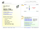
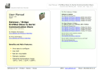
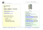
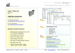
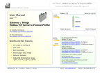
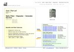
User Manual
Fiber Optic – Bridge CANbus to CANbus
Document code: MN67221FS_ENG
Revision 2.000
Page 1 of 16
Industrial Electronic Devices
User Manual
Logical
Scheme
Revision 2.000
English
Fiber Optic - Brigde CANbus to CANbus
For CANbus 2.0A and 2.0B
(Order Code: HD67221FS)
For others Repeaters:
for Website information:
www.adfweb.com?Product=HD67221FS
Similiar
Products
for Price information:
www.adfweb.com?Price=HD67221FS
Benefits and Main Features:
Low Cost
Naturally Resistant to Surges, Spikes and Electrical
Noise.
Multi Modal Optic fibre up to 2000 meters
Optic Fibres Repeaters
See also the following links:
www.adfweb.com?Product=HD67117F
www.adfweb.com?Product=HD67117FS
Benefit
www.adfweb.com?Product=HD67180F
www.adfweb.com?Product=HD67180FS
www.adfweb.com?Product=HD67181F
www.adfweb.com?Product=HD67181FS
www.adfweb.com?Product=HD67221FS
(For CANopen
and CAN 2.0A)
(For CANopen
and CAN 2.0A)
(For DeviceNET)
(For DeviceNET)
(For CAN 2.0B)
(For CAN 2.0B)
(Copper Bridge)
CANbus Repeaters
See also the following links:
www.adfweb.com?Product=HD67117
www.adfweb.com?Product=HD67180
www.adfweb.com?Product=HD67181
www.adfweb.com?Product=HD67221
(For CANopen
and CAN 2.0A)
(For DeviceNET)
(For CAN 2.0B)
(Copper Bridge)
MAX baud rate 1Mb.
Allows extension of a line segment
(without lowering the Baud Rate).
Do you have an your customer protocol?
Extension of nodes number.
See the following links:
www.adfweb.com?Product=HD67003
Different baud rate setting
Do you need to choose a device? do you want help?
CAN Protocol independent.
Ask it to the following link:
www.adfweb.com?Cmd=helpme
ADFweb.com Srl – IT31010 – Mareno – Treviso
INFO: www.adfweb.com
Phone +39.0438.30.91.31
User Manual
Fiber Optic – Bridge CANbus to CANbus
Document code: MN67221FS_ENG
Revision 2.000
Page 2 of 16
Industrial Electronic Devices
INDEX:
UPDATED DOCUMENTATION:
INDEX
UPDATED DOCUMENTATION
REVISION LIST
WARNING
TRADEMARKS
CHARACTERISTICS
COMPOSITOR SW67221
COMMUNICATION
SET COMMUNICATION
CONFIGURATION OF THE cobID
UPDATE DEVICE
CHARACTERISTICS OF THE CABLES
SERIES “FS”
SERIES “F”
CONNECTION SCHEME
MECHANICAL DIMENSIONS
ORDER CODE
ACCESSORIES
WARRANTIES AND TECHNICAL SUPPORT
RETURN POLICY
PRODUCTS AND RELATED DOCUMENTS
Page
2
2
2
2
2
3
4
6
7
9
10
11
12
13
14
15
15
15
16
16
16
Dear customer, we thank you for your attention and we remind you that you
need to check that the following document is:
Updated
Related to the product you own
To obtain the most recently updated document, note the “document code” that
appears at the top right-hand corner of each page of this document.
With this “Document Code” go to web page www.adfweb.com/download/ and
search for the corresponding code on the page. Click on the proper “Document
Code” and download the updates.
To obtain the updated documentation for the product that you own, note the
“Document Code” (Abbreviated written "Doc. Code" on the label on the product)
and download the updated from our web site www.adfweb.com/download/
REVISION LIST:
Revision
Date
Author
Chapter
Description
1.000
1.001
1.002
2.000
28/10/2006
22/06/2007
26/06/2007
09/10/2008
Av
Av
Av
Fl
All
All
All
All
First release version
Revision
Revision
New document format
WARNING:
ADFweb.com reserves the right to change informations in this manual about our
product without warning.
ADFweb.com is not responsible for any error this manual may contain.
TRADEMARKS:
All trademarks mentioned in this document belong to their respective owners.
ADFweb.com Srl – IT31010 – Mareno – Treviso
INFO: www.adfweb.com
Phone +39.0438.30.91.31
User Manual
Fiber Optic – Bridge CANbus to CANbus
Document code: MN67221FS_ENG
Revision 2.000
Page 3 of 16
Industrial Electronic Devices
CHARACTERISTICS:
The Configurable CAN Filter CobID Gateway is a mountable electronic device on rail DIN with an autonomous energy supply that allows the
following:
two-directional translation of information between two distinct CAN Buses .
Electrical isolation between two Buses .
Filter of CAN frames.
Temperature range -30°C to 70°C
The Configurable CAN must be used for interfacing two CAN lines. Otherwise, in order to extend the length and electrical isolation of more
branches than CANopen line you must use CAN Repeater device (note: view PRODUCTS AND RELATED DOCUMENTS ).
To configure the CAN Gateway, use the available software that runs with Windows, called Compositor SW67221. It is downloadable on the site
www.adfweb.com and its operation is described in this document.
The Configurable CAN Gateway can be configured up to a maximum of 2048 CobID for CAN2.0A and up to 2000 CobID for CAN2.0B.
ADFweb.com Srl – IT31010 – Mareno – Treviso
INFO: www.adfweb.com
Phone +39.0438.30.91.31
User Manual
Fiber Optic – Bridge CANbus to CANbus
Document code: MN67221FS_ENG
Revision 2.000
Page 4 of 16
Industrial Electronic Devices
COMPOSITOR SW67221:
INTRODUCTION
The device Configurable Gateway CAN , allows a CAN line to communicate with another different CAN line that we simply call CAN 0 and CAN 1
in this manual.
The two networks are symmetrical at a logical level. What CAN 0 can do to CAN 1, so can CAN 1 do to CAN 0.
CAN 0 and CAN 1 are different only on the level of hardware. One of the two CANopen has the power supply in common with the logic of the
device. The other CANopen is isolated based on the logic of the device.
In order to:
Define the Baud rate of CAN0 and CAN1
Define the Type of CAN Network (2.0A or 2.0B)
Define which CAN frames from CAN0 to CAN1.
Define which CAN frames from CAN1 to CAN0.
Update the new configurations of the device.
Save, duplicate, modify, export the configurations.
The software needed to perform the above on your PC is
Compositor SW67221.
When launching it the right window appears:
(The
SW67004
is
downloadable
on
the
site
http://www.adfweb.com/home/download/download.asp
This manual is referenced to the last version of the software
present on our web site)
Figure 1: Main window for SW67221
ADFweb.com Srl – IT31010 – Mareno – Treviso
INFO: www.adfweb.com
Phone +39.0438.30.91.31
User Manual
Fiber Optic – Bridge CANbus to CANbus
Document code: MN67221FS_ENG
Revision 2.000
Page 5 of 16
Industrial Electronic Devices
The “New Project” button creates the folder which contains all the project files:
The project is the complex of files that define a particular configuration of device Configurable CANopen to CANopen. This file can also be
imported and exported.
To clone the configurations of a Configurable CANopen to CANopen Gateway in order to configure another device in the same manner, it
is necessary to maintain the folder and all its contents.
To clone a project in order to obtain a different version of the project, it is sufficient to duplicate the project folder with another name
and open the new folder with the button “Open Project”.
When the project is created or open, it is possible to access the various configuration sections of the device:
Set Communication,
Set CobID Access.
ADFweb.com Srl – IT31010 – Mareno – Treviso
INFO: www.adfweb.com
Phone +39.0438.30.91.31
User Manual
Fiber Optic – Bridge CANbus to CANbus
Document code: MN67221FS_ENG
Revision 2.000
Page 6 of 16
Industrial Electronic Devices
COMMUNICATION:
This section defines the fundamental
communication parameters of two
BUSes where the
Configurable
CANopen Gateway is inserted.
ADFweb.com Srl – IT31010 – Mareno – Treviso
INFO: www.adfweb.com
Phone +39.0438.30.91.31
User Manual
Fiber Optic – Bridge CANbus to CANbus
Document code: MN67221FS_ENG
Revision 2.000
Page 7 of 16
Industrial Electronic Devices
Section “Set Communications”:
By pressing the “Set Communication” button, the previous window appears in which the BUS
can be set from both sides.
In the check box Baud rate set by Dip-Switch, define if Baud rate is set to Dip-Switch
or select like parameter in the software. You can select one can to Dip and the other
like parameter.
In the fields Baud Rate, the velocity of the two Buses are defined.
The parameter Type of CAN Network define if CAN is 2.0A (CobID at 11 Bit) or 2.0B
(CobID at 29 Bit)
The parameter Positive Implementation define if only the CobId write in table (Set
CobID Access) are passed to the other CAN bus (Positive Implementation is checked) or
if all the CobID write in table are block to the gateway (Positive Implementation isn’t
checked)
ADFweb.com Srl – IT31010 – Mareno – Treviso
INFO: www.adfweb.com
Phone +39.0438.30.91.31
User Manual
Fiber Optic – Bridge CANbus to CANbus
Document code: MN67221FS_ENG
Revision 2.000
Page 8 of 16
Industrial Electronic Devices
Baud rate select by Dip-Switch
The Baud rate of CAN0 and CAN1 could be defined through the dip-switch present in device. These are the combinations permissible.
Dip n° 1, 2, 3, 4 CAN1 setting
Dip n° 5, 6, 7, 8 CAN0 setting
Speed CAN1 BPS
(Only for “F” Series)
Speed CAN0 BPS
10K
20K
50K
100K
125K
250K
500K
800K
1000K
ADFweb.com Srl – IT31010 – Mareno – Treviso
Dip 1
Dip 2
Dip 3
Dip 4
Dip 5
Dip 6
Dip 7
Dip 8
ON
OFF
ON
OFF
ON
OFF
ON
OFF
ON
OFF
ON
ON
OFF
OFF
ON
ON
OFF
OFF
OFF
OFF
OFF
ON
ON
ON
ON
OFF
OFF
OFF
OFF
OFF
OFF
OFF
OFF
OFF
ON
ON
INFO: www.adfweb.com
Phone +39.0438.30.91.31
User Manual
Fiber Optic – Bridge CANbus to CANbus
Document code: MN67221FS_ENG
Revision 2.000
Page 9 of 16
Industrial Electronic Devices
CONFIGURATION OF THE CobID
Section “SET CobID Access”
The following objects can be defined:
Which CAN frames of the CAN 0 pass into CAN 1.
Which CAN frames of the CAN 1 pass into CAN 0.
If the parameter Positive Implementation is set, is possible
change the CobID of the frame when pass from one CAN bus
to the other. To do it is necessary to insert the new Cob in
the column modify CObID.
The Dimension of Data and its value don’t change when pass
into the gateway.
Example 1:
If i want to pass from CAN0 to CAN1 Network the CobID
0x181 and set it like 0x189 in CAN1 i need to set the follow
parameter in table “CAN0 to CAN1”:
Original CobID 0x181
Modify CobID 0x189
Fig 2: Set CobID Access
I must write that is represented on the right image
(only the first row) (Fig 2):
In the right example:
All the Can frames with CobID different from Original CobID Column are forgotten. The Can frames with CobID equal to the Original CobID
column are send to CAN1 with the new CobID
The column data has the following meaning:
“Original CobID” indicate the CobIDs can pass to the other CAN network (if Positive Implementation is not checked then indicate the
CobID cannot pass to other CAN Network)
“Modify CobID” indicate the new CobID of frame when it pass in the other CAN Network (only if Positive Implementation is checked)
“Description” indicate the description of the Can Frame
ADFweb.com Srl – IT31010 – Mareno – Treviso
INFO: www.adfweb.com
Phone +39.0438.30.91.31
User Manual
Fiber Optic – Bridge CANbus to CANbus
Document code: MN67221FS_ENG
Revision 2.000
Page 10 of 16
Industrial Electronic Devices
UPDATE DEVICE:
Section “UP Date Device”:
In order to load the parameters after they are set, you must click the
button “create file binary”
on the principal window. When the
processing is complete, click on “Generate Firmware”.
On the “Generate firmware window”, select the original firmware of the
device “open firmware”. Click on “Execute Modify File SX”.
At this point, the update occurs
documentation on flash write). Boot
jumper.
like our other products (see
the Gateway with the provided
Select the serial port which performs the update. Click on “Execute
Update Firmware”. Wait for the running bar to finish. Remove the
jumper and reboot the Gateway.
ADFweb.com Srl – IT31010 – Mareno – Treviso
INFO: www.adfweb.com
Phone +39.0438.30.91.31
User Manual
Fiber Optic – Bridge CANbus to CANbus
Document code: MN67221FS_ENG
Revision 2.000
Page 11 of 16
Industrial Electronic Devices
CHARACTERISTICS OF THE CABLES:
The connection from RS232 socket to a serial port (example one from a personal computer), must be made with a Null Modem cable (a serial
cable where the pins 2 and 3 are crossed).
It is recommended that the RS232 Cable not exceed 15 meters.
The connection at Ethernet socket must be with a Ethernet Cable with a RJ45 Plug
The connection at RS485 socket must be done with twisted and shielded cable.
The terminal resistor must be inserted when the HD67102 is at the end of the line, using the Terminator jumper.
Can bus cable characteristics:
DC parameter:
Impedance
AC parameters:
Impedance
delay
120 Ohm/m
5 ns/m
Length
Baud Rate [bps]
10 K
20 K
50 K
100 K
125 K
250 K
500 K
800 K
1000 K
Length MAX [m]
5000
2500
1000
650
500
250
100
50
25
ADFweb.com Srl – IT31010 – Mareno – Treviso
70
Ohm/m
INFO: www.adfweb.com
Phone +39.0438.30.91.31
User Manual
Fiber Optic – Bridge CANbus to CANbus
Document code: MN67221FS_ENG
Revision 2.000
Page 12 of 16
Industrial Electronic Devices
“FS” SERIES
Bridges and repeaters for CANbus,
CANopen, DeviceNET, J1939, CAN2.0A,
CAN2.0B
This series of device use the large
bandwidth of optics fibres for extend the
CAN bus link.
HD67221FS CANbus to fiber optic – Data
bridge repeaters
ADFweb.com Srl – IT31010 – Mareno – Treviso
INFO: www.adfweb.com
Phone +39.0438.30.91.31
User Manual
Fiber Optic – Bridge CANbus to CANbus
Document code: MN67221FS_ENG
Revision 2.000
Page 13 of 16
Industrial Electronic Devices
“F” SERIES
Bridges
and
repeaters
for
CANbus, CANopen, DeviceNET,
J1939, CAN2.0A, CAN2.0B
HD67221F CANbus to fiber optic
– Data bridge repeaters
ADFweb.com Srl – IT31010 – Mareno – Treviso
INFO: www.adfweb.com
Phone +39.0438.30.91.31
User Manual
Fiber Optic – Bridge CANbus to CANbus
Document code: MN67221FS_ENG
Revision 2.000
Page 14 of 16
Industrial Electronic Devices
CONNECTION SCHEME:
CAN 1
Baud Rate Setting [BPS]
(Only for “F” Series)
1234 5678
OFF
ON
10K
OFF
ON
OFF
ON
OFF
ON
1234 5678
1234 5678
OFF
ON
OFF
ON
20K
OFF
ON
OFF
ON
50K
ON
OFF
OFF
ON
1234 5678
OFF
ON
OFF
ON
CAN 0
Baud Rate Setting [BPS]
1234 5678
ON
OFF
OFF
ON
100K
OFF
ON
OFF
ON
1234 5678
ON
OFF
OFF
ON
ON
OFF
ON
OFF
ON
OFF
ON
OFF
OFF
ON
ON
OFF
OFF
ON
125K
ON
OFF
OFF
ON
250K
OFF
ON
OFF
ON
500K
OFF
ON
OFF
ON
800K
ON
OFF
OFF
ON
1234 5678
1234 5678
1234 5678
1234 5678
20K
= Open
50K
Connector1:
Power Supply
100K
V- = Ground
V+ = Positive wire
125K
12/18 VAC – 4 VA
12/24 VDC – 4 Watt
1234 5678
1234 5678
1234 5678
= 120 ohm
Connector3:
CAN 0
H = High wire
S = Shield
L = Low wire
V – V+ TX
RX
H S L
CAN1
TX
RX
CAN0
Hi Grd Lo
1234 5678
250K
Led3:
Green
RUN
1234 5678
500K
1234 5678
800K
1234 5678
1,000K
Jumper2:
Side “0”
Termination CAN Bus
OFF
ON
OFF
ON
1,000K
Rail DIN
Clamp
12345678
OFF
ON
OFF
ON
Connector2:
CAN 1
ON
OFF
1234 5678
10K
Port RS232 (D-SUB9-Male)
PIN2 = TX
PIN3 = RX
PIN5 = GND
Used for:
A) Programmation Port
B) Modbus on RS232
12 Vac
Or
24 dc
-- +
To connect the device to the COM
port of a PC in order to set it.
You have to use the programming
cable AC34107.
CABLE
Side A
FEM
9 8 7 6
5 4 3 2 1
Or a cable made as showed here:
Led2:
Yellow:
Change state if
the CAN frame
pass into CAN1
Led1:
Green:
Change state if
the CAN frame
pass into CAN0
Jumper2:
Boot mode
= Yes Jumper
Boot Mode
= No Jumper
Normal Mode
CABLE
Side B
FEM
ADFweb.com Srl – IT31010 – Mareno – Treviso
INFO: www.adfweb.com
Phone +39.0438.30.91.31
User Manual
Fiber Optic – Bridge CANbus to CANbus
Document code: MN67221FS_ENG
Revision 2.000
Page 15 of 16
Industrial Electronic Devices
MECHANICAL DIMENSIONS:
ORDER CODE:
HD67221F
HD67221FS
-
Data bridge repeaters
(*) Regarding “F” and “FS” series difference, see the above “Baud Rate Table”.
ACCESSORIES:
Order Code: AC34107
-
Null Modem Cable Fem/Fem DSub 9 Pin 1,5 m
Order Code: AC34114
- Null Modem Cable Fem/Fem DSub 9 Pin 5 m
Order Code: AC34001
-
Rail DIN - Power Supply 220/240V AC 50/60Hz – 12 V AC
Order Code: AC34002
-
Rail DIN - Power Supply 110V AC 50/60Hz – 12 V AC
ADFweb.com Srl – IT31010 – Mareno – Treviso
INFO: www.adfweb.com
Phone +39.0438.30.91.31
User Manual
Fiber Optic – Bridge CANbus to CANbus
Document code: MN67221FS_ENG
Revision 2.000
Page 16 of 16
Industrial Electronic Devices
WARRANTIES AND TECHNICAL SUPPORT:
For fast and easy technical support for your ADFweb.com SRL products, consult our internet support at www.adfweb.com.
Otherwise contact us at the address [email protected]
RETURN POLICY:
If while using your product you have any problem and you wish to exchange or repair it, please do the following:
1) Obtain a Product Return Number (PRN) from our internet support at www.adfweb.com. Together with the request, you need to provide detailed information
about the problem.
2) Send the product to the address provided with the PRN, having prepaid the shipping costs (shipment costs billed to us will not be accepted).
If the product is within the warranty of twelve months, it will be repaired or exchanged and returned within three weeks. If the product is no longer under warranty, you
will receive a repair estimate.
PRODUCTS AND RELATED DOCUMENTS:
Part
Description
URL
HD67121
Gateway CANopen / Canopen
www.adfweb.com?Product=HD67121
HD67001
Gateway CANopen / Modbus – RTU Master
www.adfweb.com?Product=HD67001
HD67004
HD67005
Gateway CANopen / Modbus – Ethernet TCP
www.adfweb.com?Product=HD67004
HD67134
Gateway CANopen / DeviceNet
www.adfweb.com?Product=HD67134
HD67117
CAN bus Repeater
www.adfweb.com?Product=HD67117
HD67216
CAN bus Analyzer
www.adfweb.com?Product=HD67216
ADFweb.com Srl – IT31010 – Mareno – Treviso
INFO: www.adfweb.com
Phone +39.0438.30.91.31