1
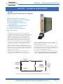
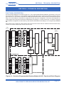
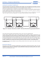
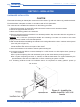
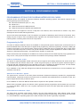
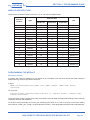
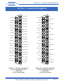
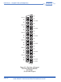
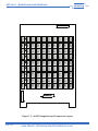
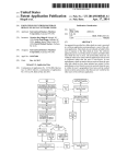
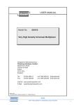
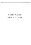
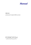
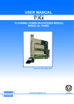
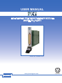
pickering
USER MANUAL
HIGH DENSITY PRECISION RESISTOR MODULE
(MODEL No. 40-297)
Issue 2.6 October 2011
pickering
www.pickeringtest.com
HIGH DENSITY PRECISION RESISTOR MODULE 40-297
ISO 9002
Reg No. FM38792
Page 1
pickering
© COPYRIGHT (2011) PICKERING INTERFACES. ALL RIGHTS RESERVED.
No part of this publication may be reproduced, transmitted, transcribed, translated or stored in any form, or
by any means without the written permission of Pickering Interfaces.
Technical details contained within this publication are subject to change without notice.
Page ii
HIGH DENSITY PRECISION RESISTOR MODULE 40-297
pickering
TECHNICAL SUPPORT
For Technical Support please contact Pickering Interfaces either by phone, fax, the website or via e-mail.
WARRANTY
All products manufactured by Pickering Interfaces are warranted against defective materials and workmanship for a period of two
years, excluding PXI chassis, from the date of delivery to the original purchaser. Any product found to be defective within this period
will, at the discretion of Pickering Interfaces be repaired or replaced.
Products serviced and repaired outside of the warranty period are warranted for ninety days.
Extended warranty and service are available. Please contact Pickering Interfaces by phone, fax, the website or via e-mail.
ENVIRONMENTAL POLICY
Pickering Interfaces operates under an environmental management system similar to ISO 14001.
Pickering Interfaces strives to fulfil all relevant environmental laws and regulations and reduce wastes and releases to the
environment. Pickering Interfaces aims to design and operate products in a way that protects the environment and the health and
safety of its employees, customers and the public. Pickering Interfaces endeavours to develop and manufacture products that can
be produced, distributed, used and recycled, or disposed of, in a safe and environmentally friendly manner.
Observe the Electrical Hazard Warning detailed in Section 8.
Observe the Electrostatic Sensitive Device Caution detailed in Section 8.
Worldwide Technical Support and Product Information
http://www.pickeringtest.com
Pickering Interfaces Headquarters
Stephenson Road Clacton-on-Sea CO15 4NL United Kingdom
Tel:
+44 (0)1255-687900
Fax:
+44 (0)1255-425349
E-Mail:
[email protected]
Pickering Interfaces Inc.
2900 Northwest Vine Street
Grants Pass
Oregon 97526
USA
Pickering Interfaces GmbH
Johann-Karg-Straße 30
D-85540
Haar-Salmdorf
Germany
Pickering Interfaces AB
Karl Nordströmsväg 31
432 53
Varberg
Sweden
Tel: +1 541 471 0700
Fax: +1 541 471 8828
E-Mail: [email protected]
Tel: +49 89 125 953 160
Fax: +49 89 125 953 189
E-Mail: [email protected]
Tel: +46 340-69 06 69
Fax: +46 340-69 06 68
E-Mail: [email protected]
Pickering Interfaces Inc.
(East Coast Regional Office)
12 Alfred Street Suite 300-3
Woburn Massachusetts 01801
USA
Pickering Interfaces s.r.o.
Smetanova 525
ˇ
Trinec
739 61
Czech Republic
Pickering Interfaces SARL
6 Rue De La Mare Blanche
77186 Noisiel
Marne Le Vallee
France
Tel: +1 781 897 1710
Fax: +1 781 897 1701
E-mail: [email protected]
Tel: +42 0558 339 168
Fax: +42 0558 340 888
E-mail: [email protected]
Tel +33 1 60 53 55 50
Fax +33 1 60 53 55 99
email [email protected]
HIGH DENSITY PRECISION RESISTOR MODULE 40-297
Page iii
pickering
THIS PAGE INTENTIONALLY BLANK
Page iv
HIGH DENSITY PRECISION RESISTOR MODULE 40-297
pickering
CONTENTS
Copyright Statement........................................................... ii
Technical Support and Warranty........................................ iii
Contents (this page)............................................................ v
Section 1
Technical Specification....................................................... 1.1
Section 2
Technical Description......................................................... 2.1
Functional Description.................................................. 2.1
Guidance on Using the Module.................................... 2.2
Section 3
Installation............................................................................ 3.1
Hardware Installation.................................................... 3.1
Software Installation..................................................... 3.2
Soft Front Panel Installation......................................... 3.2
Section 4
Programming Guide............................................................ 4.1
Programming Options For Pickering PXI Cards........ 4.1
Module Architecture...................................................... 4.3
Using The Soft Front Panel.......................................... 4.5
Section 5
Connector Information........................................................ 5.1
Section 6
Trouble Shooting................................................................. 6.1
Section 7
Maintenance Information.................................................... 7.1
Software Update............................................................ 7.1
Verification & Adjustment Procedure.......................... 7.2
Verification Test Results............................................... 7.5
Relay Lookup Tables..................................................... 7.8
Section 8
Warnings and Cautions...................................................... 8.1
HIGH DENSITY PRECISION RESISTOR MODULE 40-297
Page v
pickering
THIS PAGE INTENTIONALLY BLANK
Page vi
HIGH DENSITY PRECISION RESISTOR MODULE 40-297
SECTION 1 - TECHNICAL SPECIFICATION
pickering
SECTION 1 - TECHNICAL SPECIFICATION
40-297
High Density Precision Resistor Module
PRECISION RESISTOR
40-297
● High Density Resistor Simulation
● Up To 18 Channels in a One Slot Module
● Short and Open Simulation
● Simple Software Control Through
Resistance Calls
● VISA & Kernel Drivers Supplied for
Windows 2000/XP/Vista
● Supported by PXI or LXI Chassis
● 2 Year Warranty
The 40-297 provides a simple solution for applications
requiring accurate simulation of resistive sensors. The 40-297
is available in a variety of resistance ranges and resolution
capabilities that meet the needs of most functional test
systems. It is particularly well suited to applications such
as the testing of engine controllers where resistive sensors
provide information on parameters such as temperature.
Each channel of the 40-297 module is able to simulate the
common short circuit and open circuit conditions that can be
experienced in a system due to faulty wiring or sensors.
Software control of the 40-297 is simplified by the use of
simple resistor value calls. The module works out the channel
setting closest to the requested value and sets that value. The
user can interrogate the module to find the actual resistance
setting used by the module.
A calibration cable assembly is attached to the module
to enable an external DMM to be connected to each
channel in turn to support the process of verification. This
considerably simplifies the effort required to check the
module’s calibration. Verification is performed with the UUT
disconnected from the module.
The 40-297 is available in three standard builds - a narrow
range 18 channel version, a medium range 9 channel version
and a wide range 6 channel fine resolution version - that suit
the most common configurations required.
For applications requiring greater resolution and accuracy, or
to support calibration with the UUT connected, users should
consider the 40-260 series Precision resistor Modules.
Up To 18
Switched
Resistor
37-way
D-type
Plug
Up To 18
ISSUE 2.5 OCT 2010
Offset
Resistor
Resistor
Channel
Connector
Functional Diagram for the 40-297 High Density Precision Resistor Module
PXI Switch & Instrumentation
Pickering Interfaces www.pickeringtest.com
HIGH DENSITY PRECISION RESISTOR MODULE 40-297
Page 1.1
SECTION 1 - TECHNICAL SPECIFICATION
Specification
Resistance Channels
Model
Number
40-297-001
40-297-002
Resistance
Range
1Ω to 230Ω
2Ω to 13.5kΩ 3Ω to 1.5MΩ
Setting
Resolution
1Ω
0.25Ω
0.125Ω
Number of
Channels per
Module
18
9
6
40-297-003
pickering
Other Resistor Modules
Pickering Interfaces manufacture a range of variable resistor
modules in the PXI format. If you have a requirement for a
variable resistor module please contact your local sales office
with the information below and we will advise you on the
best solution for your application.
Lowest Resistance †
Highest Resistance
Resistance Resolution
Overall Accuracy
Maximum Power/Current
Number of Channels (variable resistors)
Accuracy:
resolution ±0.2%
† Resistance is as measured across the user connector terminals,
minimum resistance must have a non-zero value.
Fault Simulation:
Open and short circuit
(typically <0.3Ω)
Product Order Codes
Power:
0.5W maximum
Temperature Stability:
<50ppm
Number of Operations:
100 million (10mA)
Maximum Voltage:
100V or as limited by power
Settling time:
<3ms
Software Control:
By resistance calls to module for
selected channel.
Calibration:
4-wire resistance measurement of
selected channel for verification
purposes with UUT removed and
a special cable assembly attached.
Factory calibration data is stored
in the module.
18 Channel Precision Resistor
9 Channel Precision Resistor
6 Channel Precision Resistor
Power Requirements
+3.3V
+5V
+12V
-12V
0
4.3A max
0
0
40-297-001
40-297-002
40-297-003
Accessories:
Calibration lead for 4-wire resistance measurement using
DMM - 37-way D-type socket to shrouded 4mm bayonet
plugs, 1Meter length
40-975-037-1M
Mating Connectors & Cabling
For connection accessories for the 40-297 please refer to
the 90-007D 37 way D-type Connector Accessories data
sheet where a complete list and documentation can be
found for accessories, or refer to the Connection Solutions
catalog.
Physical Parameters
Physical characteristics:
One slot, 3U PXI.
3D models for all versions in a
variety of popular file formats are
available on request.
PCI Interface:
33MHz, 32 bit address, 16 bit data.
Signal Connectors:
Male 37-way D-type
Page 1.2
Pickering Interfaces are sponsor members of the PXI Systems Alliance www.pxisa.org
HIGH DENSITY www.pickeringtest.com
PRECISION RESISTOR
MODULE 40-297
E-Mail [email protected]
SECTION 1 - TECHNICAL SPECIFICATION
pickering
Programming
Pickering provide kernel and VISA (NI and Agilent) drivers
which are compatible with Windows 2000/XP/Vista
operating systems. The VISA driver is also compatible
with Real-Time Operating Systems such as LabVIEW RT.
Additionally, QNX is fully supported, for other RTOS support
contact Pickering.
These drivers may be used with a variety of programming
environments and applications including:
National Instruments products (LabVIEW/LabWindows/
CVI/MAX/TestStand etc.)
Microsoft Visual Studio products (Visual Basic/Visual C+)
Agilent VEE
Mathworks Matlab
Drivers for popular Linux distributions are available, other
environments are also supported, please contact Pickering
with specific enquiries.
PXI & CompactPCI Compliance
The module is compliant with the PXI Specification 2.2. Local
Bus, Trigger Bus and Star Trigger are not implemented.
Uses 33MHz 32-bit backplane interface.
Safety & CE Compliance
All modules are fully CE compliant and meet applicable EU
directives: Low-voltage safety EN61010-1:2001,
EMC Immunity EN61000-6-1:2001, Emissions EN55011:1998.
PXI & LXI Chassis Compatibility
Compatible with all chassis conforming to the 3U PXI and
3U cPCI specification. Compatible with Legacy and Hybrid
peripheral slots in a 3U PXI Express chassis.
Compatible with Pickering Interfaces LXI Modular Switching
chassis. For information on driving your switching solution in
an LXI environment refer to the LXI Short Form Catalog.
Operating/Storage Conditions
Operating Temperature:
Humidity:
Altitude:
0°C to +55°C
Up to 90% non-condensing
5000m
Storage and Transport Conditions
Storage Temperature:
-20°C to +75°C
Humidity:
Up to 90% non-condensing
Altitude:
15000m
Please refer to the Pickering
Interfaces “Connection
Solutions” catalog for the full list
of connector/cabling options,
including drawings, photos and
specifications. This is available in
either print or as a download.
Alternatively our web site has
dynamically linked connector/
cabling options, including pricing,
for all Pickering PXI modules.
Latest Details
Please refer to our Web Site for Latest Product Details.
www.pickeringtest.com
Refer to the “PXI Product Guide”
for descriptions of Pickering
Interfaces’ comprehensive
range of PXI switching and
instrumentation modules,
including specifications and
product selection guides.
The Product Guide is available on
request or can be downloaded
from the Pickering website.
Ever wondered what PXI is all
about?
Pickering Interfaces’ “PXImate”
Explains the basics of PXI and
provides useful data for engineers
working on switch based test
systems.
The PXImate is available free on
request from the Pickering website.
The “PXI Product Catalog” gives full details of
Pickering’s entire range of PXI switch modules,
instrument modules and support products.
The PXI Product Catalog is available on request
or can be downloaded from the Pickering
website.
Pickering Interfaces are sponsor members of the PXI Systems Alliance www.pxisa.org
www.pickeringtest.com
E-Mail [email protected]
HIGH DENSITY PRECISION
RESISTOR
MODULE 40-297
Page 1.3
© Copyright (2010) Pickering Interfaces. All Rights Reserved
Pickering Interfaces maintains a commitment to continuous product development, consequently we reserve the right to vary from the description given in this data sheet.
Operating Conditions
SECTION 1 - TECHNICAL SPECIFICATION
THIS PAGE INTENTIONALLY BLANK
Page 1.4
HIGH DENSITY PRECISION RESISTOR MODULE 40-297
pickering
SECTION 2 - TECHNICAL DESCRIPTION
pickering
SECTION 2 - TECHNICAL DESCRIPTION
FUNCTIONAL DESCRIPTION
A functional block diagram is provided in Figure 2.1. The Programmable Resistor Module is powered by +5V inputs
via Compact PCI connector J1. The interface to the user test equipment is via the front panel mounted 37 way D
type connector, J2. The module comprises two PCBs populated with resistor chains which are switched via dual pole
relays. The two PCBs are connected via a plug and socket connector arrangement. The relays are energised via
control signals from relay drivers which are addressed by PCI bridge U1, via the control logic. to output the required
signal. Module configuration is determined by data stored in EEPROM U9 PCI Bridge U1 is configured by EEPROM
U2.
Each resistor chain includes an offset resistor that can be used to set the minimum resistance value as well as relay
contacts to hold the channel open circuit or short circuit.
37-WAY
D TYPE
CONNECTOR
J2
RELAY
CONTACTS
RELAY
COILS
COMPACT PCI
BUS
CONNECTOR
J1
RELAY
DRIVERS
U17 TO
U22
RESISTOR
CHAINS
TERMINATING
RESISTORS
R1 TO R12
PCI
BRIDGE
U1
CONTROL
LOGIC
U2 TO U8
+5V
0V
MODULE
CONFIGURATION
U9
PCI BRIDGE
CONFIGURATION
U2
MOTHERBOARD
RELAY
CONTACTS
RESISTOR
CHAINS
RELAY
COILS
RELAY
DRIVERS
U23 TO
U28
DAUGHTERBOARD
Figure 2.1 - Precision Programmable Resistor Module 40-297: Functional Block Diagram
HIGH DENSITY PRECISION RESISTOR MODULE 40-297
Page 2.1
SECTION 2 - TECHNICAL DESCRIPTION
pickering
GUIDANCE ON USING THE MODULE
The 40-297 behaves as a precise but adjustable in value resistor. The circuit elements in the design use switch
resistors with electro-mechanical relays. It can be used to simulate the type of variable resistor found in many control
systems that indicate the value of a parameter, such as temperature, strain or pressure.
The 40-297 responds directly to a request for a particular value of resistance and is therefore very easy to use in
a system. Applications programs are easily generated to convert, for example, temperature requests to resistance
values for different types of RTD that are to be emulated.
Each resistor channel has an “input” connection and an “output” connection. There is no significance in the label
“input” and “output” other than to identify them. The resistor channel schematic is shown in Figure 2.2.
RESISTOR CHANNEL CONNECTOR
IN
OUT
CHANNEL 1
IN
OUT
CHANNEL 2
IN
OUT
CHANNEL 18
Figure 2.2 - Resistor Channels for 40-297 18-Channel Precision Programmable Resistor
The module uses fixed resistor values switched by relays. There are no user adjustable parts
A table containing calibration data is used to convert requests for specific resistance values to a setting which most
closely corresponds to the value requested. The module contains two versions of the calibration table, one created
by Pickering Interfaces at the point of manufacture and an alternate table which can be created by the user. The
Pickering Interfaces table cannot be overwritten by the user. The user can select which table is being is used, in
the majority of applications we recommend the Pickering Interfaces table is used, creation of a user table requires
accurate measurements of many points within the module and requires a program to create with confidence. A
program is available for this purpose from Pickering Interfaces but requires the use of a specific DMM range.
For applications requiring the greatest accuracy Pickering Interfaces does offer a range of other resistor modules
with better accuracy.
Potentiometer Operation
The 40-297 can be used to simulate a potentiometer by using the two channels connected in series. The user
should decide on the value of the potentiometer to be simulated and program two channels so that the sum of their
resistances is always the same. For example, if a 5kΩ potentiometer is needed with a wiper position at 1kΩ, set one
channel to 1kΩ and the other to 4kΩ.
Page 2.2
HIGH DENSITY PRECISION RESISTOR MODULE 40-297
SECTION 3 - INSTALLATION
pickering
SECTION 3 - INSTALLATION
HARDWARE INSTALLATION
CAUTION
Electrostatic discharge can damage the components on the module. To avoid such damage in handling the board,
touch the anti-static bag to a metal part of the chassis before removing the board from the bag.
Ensure that there is adequate ventilation in accordance with the PXI Specification.
The module should be installed in accordance with the following procedure:
1. Ensure that the system is turned OFF but still connected to mains so that it remains grounded.
2. Choose an appropriate slot in the rack.
3. Remove the blanking plate for the chosen slot.
4. Ensure that the injector/ejector handle is in its downward position. Align the module with the card guides on
the top and bottom of the slot.
WARNING: Do not raise the injector/ejector handle whilst inserting the module. The module will not insert
properly unless the handle is in its downward position.
5. Hold the handle whilst slowly sliding the module into the card guides until the handle catches on the injector/
ejector rail (refer to Figure 3.1).
6. Raise the injector/ejector handle until the module firmly seats into the backplane. The front panel of the
module should be flush with the front panel of the chassis.
7. Screw the front panel of the module to the front panel mounting rail.
8. In a system employing MXI-3 to connect a desktop PC to a PXI chassis or to link multiple chassis, power-up
the system as follows:
a. For a system comprising a PC and one chassis, power up the chassis before powering up the PC.
b. For a system comprising more than one chassis, turn ON the last chassis in the system followed by the
penultimate, etc, and finally turn ON the PC or chassis containing the system controller.
9. For Pickering Interfaces modular LXI installation there is no requirement to use any particular power up
sequence.
PXI / LXI Chassis
Figure 3.1 - Installing the
module into a PXI / cPCI / LXI
Chassis
HIGH DENSITY PRECISION RESISTOR MODULE 40-297
Page 3.1
SECTION 3 - INSTALLATION
pickering
SOFTWARE INSTALLATION
First install the appropriate Pickering PXI switch card drivers by running the installer program Setup.exe, either from
the CD-ROM supplied, or by downloading the latest version from our website http://www.pickeringtest.com - the
recommended method. There are different versions of the Setup program to suit different Windows versions and
software environments. Setup is accompanied by a ReadMe file containing additional installation information. A
single installation covers all cards in the System 40, System 45 and System 50 ranges.
When installation completes, the installed drivers’ ReadMe file is offered for display. It can also be displayed later
using a shortcut on the Programs>>Pickering menu.
If you are not a LabVIEW user you should choose the “full” version, and once that has been installed run the
LabVIEW Runtime Engine installer via the shortcut on the Programs>>Pickering menu. In the absence of LabVIEW
the Runtime Engine is required to support the Pickering Test Panels application.
SOFT FRONT PANEL INSTALLATION
The installation of the soft front panel utility is through a basic windows install package found on the distribution
DVD.
1. Locate and run the installer package in the folder DVD:\Applications\Soft Front Panels. Run the installer
Setup_40-26X-SFP.exe
2. Follow the on screen instructions, selecting a different target directory if required. It is recommended that it be
installed to the default Pickering directory created during driver installation (usually C:\Pickering).
3. Once installed a new program group should be available on the Programs\Pickering menu location.
This will install the soft front panel utility and the corresponding windows help file.
To un-install, either use the windows Add/Remove Programs procedure or run the Uninstall 40-26X soft front
panel menu item in Programs\Pickering\40-26X
For instructions on how to operate the module via the Soft Front Panel, please refer to the end of Section 4
“Programming Guide” of this manual.
Figure 3.2 - Soft Front Panel For The 40-297
Page 3.2
HIGH DENSITY PRECISION RESISTOR MODULE 40-297
SECTION 4 - PROGRAMMING GUIDE
pickering
SECTION 4 - PROGRAMMING GUIDE
PROGRAMMING OPTIONS FOR PICKERING INTERFACES PXI CARDS
Software drivers are supplied for Microsoft Windows 2000/XP operating systems, with specific support for the
following development environments:
●●
●●
●●
●●
Microsoft Visual Studio (VB, C++, C#)
Borland C++
National Instruments LabWindows/CVI
National Instruments LabVIEW and LabVIEW RT
Windows drivers are supplied in the form of Dynamic Link Libraries, which should also be usable in any other
development environment that supports them.
Some recent drivers developed for the LXI platform are capable of addressing both PXI and LXI domains. Such
duality may be of help to users considering future migration from PXI based systems to LXI based systems, or
indeed systems containing both PXI and LXI components.
Programming for PXI
A number of different Windows drivers are available to meet particular system requirements, and should none of
these be suitable there is also the option of register-level programming. Drivers are generally ‘universal’, handling all
models in the System 40, 45 and 50 ranges; however some models that are not compliant with the Ivi Swtch class
cannot be used with the pi40iv IVI driver. The pipx40 and Pilpxi drivers are also applicable to certain models in the
System 41 (PXI Instruments) range - see these drivers’ System 41 support list.
Please note that this documentation is available in its most up-to-date form as HTML help files, fully hyperlinked for
easy access - both pipx40 and Pilpxi documents are included in the Pipx40vpp software installation.
IVI Driver for Windows - pi40iv
The pi40iv IVI (Interchangeable Virtual Instrument) driver supports all Pickering Interfaces PXI switch cards that
are consistent with the Iviswtch class model - as are the great majority of cards in the System 40/45/50 ranges. It
integrates well with LabWindows/CVI and LabVIEW, and is fully compatible with Switch Executive. It is also usable
in general-purpose programming environments such as Visual C++ and Visual Basic.
Prior installation of the VISA and IviEngine from National Instruments are required for the correct installation and
operation of this driver.
VISA Driver for Windows - pipx40
The pipx40 driver conforms to the VISA (Virtual Instrument Software Architecture) standard for programmable
instrumentation. Instrument control environments such as LabVIEW and LabWindows/CVI are based on VISA, and
pipx40 support libraries are provided for them.
Prior installation of VISA from National Instruments is required for the operation of this driver.
Where VISA is available, pipx40 can also be used in general-purpose programming environments such as Visual
C++ and Visual Basic. When IVI is not a system requirement this driver will often yield faster operation than the
pi40iv driver.
Direct I/ODriver for Windows - Pilpxi
The Pilpxi driver accesses cards directly, without using the VISA software layer, while offering similar overall
functionality to pipx40. It is most commonly used in general-purpose programming environments such as Visual
C++ and Visual Basic. Operating speed of the VISA and Direct I/O drivers is generally comparable.
HIGH DENSITY PRECISION RESISTOR MODULE 40-297
Page 4.1
SECTION 4 - PROGRAMMING GUIDE
pickering
Register-level Programming
Register level programming for this module is not available because of the hardware techniques and the firmware
algorithms used to convert resistance calls into specific hardware instruction based on the calibration files stored
in the module.
Programming for LXI
When Pickering PXI cards are inserted into an LXI Modular Chassis a different set of drivers is available.
IVI Driver for Windows - pi40iv
The pi40iv IVI also supports LXI inserted cards simply by changing the resource string to address string to the
appropriate address.
Direct I/ODriver for Windows - Piplx
The piplx driver is based on the PXI Direct IO driver pilpxi, but with added functionality to deal with the added need
to address the chassis using an IP address. It integrates well with LabWindows/CVI and LabVIEW, and is fully
compatible with Switch Executive. It is also usable in general-purpose programming environments such as Visual
C++ and Visual Basic.
Please note that this driver may also be used in the PXI domain. If the addressed card is in the local computer PCI/
PXI system, commands will be passed through to the PXI Direct IO driver. This mechanism allows the piplx driver
to be used for both PXI and LXI cards.
The LXI format offers additional interface options not available in PXI :
.NET
A .NET native driver is also available. Once again this may be used for both LXI and PXI card control.
SOAP
Pickering LXI products include a SOAP interface which is usable from a wide variety of platforms and languages.
SSH
Pickering LXI products include an SSH interface which allows remote command line access to control cards, or,
using a suitable package, programmatic control.
The user is advised to visit the Pickering web site for further details of all the above drivers, where documentation,
example programs, and further help with driver choice are available.
LabVIEW, LabWindows/CVI and Switch Executive are trademarks of National Instruments Corporation.
General Pickering Card Architecture
With most drivers, before programming a Pickering card it is important to understand the basic architecture of
Pickering cards.
The switches on a Pickering card are organized into logical sub-units, each sub-unit containing a set of objects of
similar type and use. These objects may be switches, digital outputs, digital inputs, resistors, power supplies etc,
depending on the nature of the specific card.
For example a simple matrix card will usually contain a single sub-unit containing the switches arranged in a
2-dimensional array. However a similar card with additional isolating relays connected to the matrix will contain
additional sub-units containing those isolation relays.
Low level drivers include functions to allow the programmer to query the card to ascertain the number of sub-units,
and the size and type of each sub-unit.
For full details of the driver functions available the programmer should refer to the documentation provided.
Page 4.2
HIGH DENSITY PRECISION RESISTOR MODULE 40-297
SECTION 4 - PROGRAMMING GUIDE
pickering
MODULE ARCHITECTURE
These resistor modules expose a total of 6, 9 or 18 sub-units as detailed below:
Sub-Unit Size
Sub-Unit
Number
Type
1
Use
40-297-001
40-297-002
40-297-003
Resistor
10
19
28
Resistor 1
2
Resistor
10
19
28
Resistor 2
3
Resistor
10
19
28
Resistor 3
4
Resistor
10
19
28
Resistor 4
5
Resistor
10
19
28
Resistor 5
6
Resistor
10
19
28
Resistor 6
7
Resistor
10
19
—
Resistor 7
8
Resistor
10
19
—
Resistor 8
9
Resistor
10
19
—
Resistor 9
10
Resistor
10
—
—
Resistor 10
11
Resistor
10
—
—
Resistor 11
12
Resistor
10
—
—
Resistor 12
13
Resistor
10
—
—
Resistor 13
14
Resistor
10
—
—
Resistor 14
15
Resistor
10
—
—
Resistor 15
16
Resistor
10
—
—
Resistor 16
17
Resistor
10
—
—
Resistor 17
18
Resistor
10
—
—
Resistor 18
PROGRAMMING THE MODULE
Resistance Control
In practice the control of resistance is not performed by controlling of the sub-units directly but rather using the
SetResistance() functions provided in the driver.
In pilpxi:
DWORD PIL_ResSetResistance(DWORD card, DWORD channel, DWORD Mode, double
resistance)
Or, in pipx40:
ViStatus pipx40_resSetResistance(ViSession vi, ViUint32 subUnit, ViUInt32 mode,
ViReal64 resistance)
These functions accept a floating point value of resistance and calculate the appropriate settings of the sub-units
required to achieve that resistance.
To set short circuit (nominally zero ohms) use a floating point value of 0.0, and to set open circuit use a floating
point value of “HUGE_VAL” (using C requires #include <math.h>, other languages should provide similar libraries).
HIGH DENSITY PRECISION RESISTOR MODULE 40-297
Page 4.3
SECTION 4 - PROGRAMMING GUIDE
pickering
LabVIEW
LabVIEW VIs are provided for the control of the resistance channels.
Figure 4.1 - Example LabVIEW VI Supplied With The Precision Resistor Module
Page 4.4
HIGH DENSITY PRECISION RESISTOR MODULE 40-297
SECTION 4 - PROGRAMMING GUIDE
pickering
USING THE SOFT FRONT PANEL
Figure 4.2 - Example Soft Front Panel Supplied With The Precision Resistor Modules
Resistor Channels
To control a card, first press the ‘Find Cards’ button to locate all suitable resistor cards in the PCI/PXI system.
Select the required card from the pull-down list then press the ‘Connect’ button to establish a control session on the
selected card.
There are buttons on the right hand side of the soft front panel, one for each of the card’s programmable resistor
channels, select the required resistor tab.
The coarse control allows the resistor to be set to a precision of 1Ω between the minimum and maximum values.
The fine control offers a range of +/- 1Ω with a precision of 0.01Ω.
These rotary controls may be operated using the mouse, however for closer control, the keyboard ‘Page Up’ and
‘Page Down’ keys will change the setting by 100Ω and 50mΩ respectively. The keyboard up-arrow and down-arrow
keys will change the setting by 1Ω and 10mΩ respectively.
Three ‘radio buttons’ on the SFP allow the currently selected resistor element to be set as open circuit, short circuit
or the displayed resistance value.
In the SFP ‘File’ menu, there are options to save and load card settings to file.
Note: The “Voltage Reference” pull-down list and the “Monitor” control buttons on the right hand side of the SFP are
not applicable to the 40-297 module.
HIGH DENSITY PRECISION RESISTOR MODULE 40-297
Page 4.5
SECTION 4 - PROGRAMMING GUIDE
THIS PAGE INTENTIONALLY BLANK
Page 4.6
HIGH DENSITY PRECISION RESISTOR MODULE 40-297
pickering
SECTION 5 - CONNECTOR INFORMATION
pickering
SECTION 5 - CONNECTOR INFORMATION
CH1 IN
20
CH2 IN
21
CH3 IN
CH4 IN
CH5 IN
CH6 IN
CH7 IN
CH8 IN
CH9 IN
CH10 IN
CH11 IN
CH12 IN
22
23
24
25
26
27
28
29
30
31
CH13 IN
32
CH14 IN
33
CH15 IN
34
CH16 IN
CH17 IN
CH18 IN
35
36
37
1
CH1 OUT
2
CH2 OUT
3
CH3 OUT
4
CH4 OUT
5
CH5 OUT
6
CH6 OUT
7
CH7 OUT
8
CH8 OUT
9
CH9 OUT
10
CH10 OUT
11
CH11 OUT
12
CH12 OUT
13
CH13 OUT
14
CH14 OUT
15
CH15 OUT
16
CH16 OUT
17
CH17 OUT
18
CH18 OUT
19
FP_GND
Figure 5.1 - Pin Outs: 18-Channel
Precision Resistor Module
40-297-001
(37-pin male D-type)
CH1 IN
20
NC
21
CH2 IN
22
NC
23
CH3 IN
24
NC
25
CH4 IN
26
NC
27
CH5 IN
28
NC
29
CH6 IN
30
NC
31
CH7 IN
32
NC
33
CH8 IN
34
NC
35
CH9 IN
36
NC
37
1
NC
2
CH1 OUT
3
NC
4
CH2 OUT
5
NC
6
CH3 OUT
7
NC
8
CH4 OUT
9
NC
10
CH5 OUT
11
NC
12
CH6 OUT
13
NC
14
CH7 OUT
15
NC
16
CH8 OUT
17
NC
18
CH9 OUT
19
FP_GND
Figure 5.2 - Pin Outs: 9-Channel
Precision Resistor Module
40-297-002
(37-pin male D-type)
HIGH DENSITY PRECISION RESISTOR MODULE 40-297
Page 5.1
SECTION 5 - CONNECTOR INFORMATION
CH1 IN
20
NC
21
NC
22
CH2 IN
23
NC
24
NC
25
CH3 IN
26
NC
27
NC
28
CH4 IN
29
NC
30
NC
31
CH5 IN
32
NC
33
NC
34
CH6 IN
35
NC
36
NC
37
pickering
1
NC
2
NC
3
CH1 OUT
4
NC
5
NC
6
CH2 OUT
7
NC
8
NC
9
CH3 OUT
10
NC
11
NC
12
CH4 OUT
13
NC
14
NC
15
CH5 OUT
16
NC
17
NC
18
CH6 OUT
19
FP_GND
Figure 5.3 - Pin Outs: 6-Channel
Precision Resistor Module
40-297-003
(37-pin male D-type)
Page 5.2
HIGH DENSITY PRECISION RESISTOR MODULE 40-297
SECTION 6 - TROUBLE SHOOTING
pickering
SECTION 6 - TROUBLESHOOTING
INSTALLATION PROBLEMS
The Plug & Play functionality of Pickering switch cards generally ensures trouble-free installation.
If you do experience any installation problems you should first ensure that all cards are properly seated in their slots.
Improperly mated cards may go undetected by the operating system, or may be detected as a card of an unknown
type. They can also cause the computer to freeze at various stages in the boot sequence.
If your system employs MXI-3 you should check the integrity of all MXI-3 links. When the system is powered up, and
during Windows start-up, you should expect to see periodic activity on the MXI-3 RX/TX (yellow) indicators, clearing
to leave only the PWR/LNK (green) LEDs illuminated. The RX/TX indicators should show activity when you attempt
to access a card.
DIAGNOSTIC UTILITY
The Pickering Diagnostic Utility (accessible through the Programs>>Pickering>>PXI Utilities menu) generates a
diagnostic report of the system’s PCI configuration, highlighting any potential configuration problems. Specific details
of all installed Pickering switch cards are included. All the installed Pickering switch cards should be listed in the
“Pilpxi information” section - if one or more cards is missing it may be possible to determine the reason by referring to
the PCI configuration dump contained in the report, but interpretation of this information is far from straightforward,
and the best course is to contact Pickering support: [email protected], if possible including a copy of the
diagnostic report.
In the “VISA information” section, if VISA is not installed it’s absence will be reported. This does not affect operation
using the Direct I/O driver, and is not a problem unless you wish to use VISA. VISA is a component of National
Instruments LabWindows/CVI and LabVIEW, or is available as a standalone environment.
If VISA is present and is of a sufficiently recent version, the section “Pipx40 information” should present a listing
similar to “Pilpxi information”.
Please note that the Diagnostic Utility cannot access cards if they are currently opened by some other application,
such as the Test Panels or Terminal Monitor.
HIGH DENSITY PRECISION RESISTOR MODULE 40-297
Page 6.1
SECTION 6 - TROUBLE SHOOTING
THIS PAGE INTENTIONALLY BLANK
Page 6.2
HIGH DENSITY PRECISION RESISTOR MODULE 40-297
pickering
SECTION 7 - MAINTENANCE INFORMATION
pickering
SECTION 7 - MAINTENANCE INFORMATION
SOFTWARE UPDATE
For PXI modules operating in a PXI chassis, no module software updates are required. For the latest version of
the driver please refer to our web site www.pickeringtest.com where links to our Software Download page will
provide the latest version of the driver software for the various programming environments encountered.
For PXI modules which are supported in one of Pickering Interfaces’ Modular LXI Chassis (such as the 60-102
and 60-103) no module software update is required. If the module was introduced after the LXI chassis was
manufactured the module may not be recognized, in this case the chassis firmware may need upgrading. This
is a simple process which is described in the manual for the Modular LXI Chassis.
HIGH DENSITY PRECISION RESISTOR MODULE 40-297
Page 7.1
SECTION 7 - MAINTENANCE INFORMATION
pickering
VERIFICATION & ADJUSTMENT PROCEDURE
This section provides a procedure for verifying that the 40-297 is performing to specification and guidance on
adjustment.
In normal use the 40-297 does not require regular adjustment. Where procedures require regular verification
checks of instrumentation in a system Pickering Interfaces recommend a 1 year interval between tests. In many
applications much longer calibration intervals can be used.
Verification
Depending on the customer’s requirements a verification check can be made periodically by connecting to the front
panel resistor channel port to check the module is within specification. The module has an internal date counter
that shows a message in the diagnostics after this time but will not effect the cards operation. The customer has the
option to read and reset the verification/calibration date as required via the following programming functions:
PIL_ReadCalDate
PIL_WriteCalDate
The module also has two internal calibration stores User_Store & Factory_Store which contain the same calibration
information when leaving the factory. Resistance calls are made using the calibration values in the User_Store, in
nearly all cases no changes to either store will be required, if the User_Store is accidently modified the Factory_
Store can be copied to the User_Store to recover the factory calibration.
Page 7.2
HIGH DENSITY PRECISION RESISTOR MODULE 40-297
SECTION 7 - MAINTENANCE INFORMATION
pickering
Verification Procedure
The verification procedure is describes a set of measurements that is adequate to check that the module is performing
to specification.
Calibration/verification of the 40-297 requires the use of a precision DMM capable of 4 terminal resistance
measurements.
Measurement of the 40-297 can be simplified by use of the cable assembly shown in Fig 7.3. connected to the DMM.
6½ Digit DMM
40-297
CH1 IN
CH2 IN
CH3 IN
CH4 IN
CH5 IN
CH6 IN
CH7 IN
CH8 IN
CH9 IN
CH10 IN
CH11 IN
CH12 IN
CH13 IN
CH14 IN
CH15 IN
CH16 IN
CH17 IN
CH18 IN
20
21
22
23
24
25
26
27
28
29
30
31
32
33
34
35
36
37
1
2
3
4
5
6
7
8
9
10
11
12
13
14
15
16
17
18
CH1 OUT
CH2 OUT
CH3 OUT
CH4 OUT
CH5 OUT
CH6 OUT
CH7 OUT
CH8 OUT
CH9 OUT
CH10 OUT
CH11 OUT
CH12 OUT
CH13 OUT
CH14 OUT
CH15 OUT
CH16 OUT
CH17 OUT
CH18 OUT
V,Ω+
I+
V,Ω-
I-
Calibration Cable
40-975-037-1M
Figure 7.1 - Calibration of the 40-297 using a DMM with 4-wire resistance
measurement and the 40-975-037-1M cable
Each “input” and each “output” is linked together so all the installed channels are in parallel. Once connected in this
way, the user can check each channel of the module in turn by setting all channels to the open position except for
the single channel to be measured.
The DMM is then used to measure the resistance with the module settings shown in Table 7.1 for each channel. The
resistance settings are model dependent as shown.
HIGH DENSITY PRECISION RESISTOR MODULE 40-297
Page 7.3
SECTION 7 - MAINTENANCE INFORMATION
pickering
Table 7.1 - Calibration Resistance Settings For Each Model
40-297-001
40-297-002
40-297-003
Short (0Ω)
Short (0Ω)
Short (0Ω)
1Ω
2Ω
3Ω
1.5Ω
2.15Ω
3.06Ω
2.5Ω
2.4Ω
3.2Ω
3.5Ω
2.75Ω
3.375Ω
7.5Ω
3.75Ω
4.875Ω
15.5Ω
5.75Ω
5.875Ω
31.5Ω
9.75Ω
7.875Ω
63.5Ω
17.75Ω
11.875Ω
127.5Ω
33.75Ω
19.875Ω
230Ω
65.75Ω
35.875Ω
—
129.75Ω
67.875Ω
—
256Ω
128Ω
—
512Ω
256Ω
—
1024Ω
512Ω
—
2048Ω
1024Ω
—
4096Ω
2048Ω
—
8000Ω
4096Ω
—
13500Ω
8000Ω
—
—
16000Ω
—
—
32000Ω
—
—
64000Ω
—
—
128000Ω
—
—
256000Ω
—
—
512000Ω
—
—
1024000Ω
—
—
1500000Ω
For convenience, Tables 7.2, 7.3 and 7.4 on the following pages are provided for a means of recording calibration
results for one channel of each model.
Adjustment Procedure
The 40-297 contains no user adjustable parts, it uses a calibration table that is used to allow the module to respond
to requests for specific values of resistance. Two tables are supported, a factory table and a user table. For normal
use we recommend that only the factory table is used. For applications requiring better accuracy we suggest using
one of the 40-260 series modules.
Although it is possible to modify the calibration table we recommend that modifications to calibration information is
carried out by Pickering Interfaces. Calibration table alterations are only normally required in the event of having to
replace a resistor.
Page 7.4
HIGH DENSITY PRECISION RESISTOR MODULE 40-297
SECTION 7 - MAINTENANCE INFORMATION
pickering
VERIFICATION TEST RESULTS
Table 7.2 - Calibration Test Results For 40-297-001
Serial Number:
Channel Number:
Date of Test:
Operator’s Name:
Test Equipment
Used:
Resistance
Setting
Measured Value
Specification Limit, 0.2% ±1Ω
Max
Min
Result
(delete as
appropriate)
Short (0Ω)
<.5Ω
0Ω
Pass / Fail
1Ω
2.002Ω
0Ω
Pass / Fail
1.5Ω
2.503Ω
0.497Ω
Pass / Fail
2.5Ω
3.505Ω
1.495Ω
Pass / Fail
3.5Ω
4.507Ω
2.493Ω
Pass / Fail
7.5Ω
8.515Ω
6.485Ω
Pass / Fail
15.5Ω
16.531Ω
14.469Ω
Pass / Fail
31.5Ω
32.563Ω
30.437Ω
Pass / Fail
63.5Ω
64.627Ω
62.373Ω
Pass / Fail
127.5Ω
128.755Ω
126.245Ω
Pass / Fail
230Ω
231.46Ω
228.54Ω
Pass / Fail
HIGH DENSITY PRECISION RESISTOR MODULE 40-297
Page 7.5
SECTION 7 - MAINTENANCE INFORMATION
pickering
Table 7.3 - Calibration Test Results For 40-297-002
Serial Number:
Channel Number:
Date of Test:
Operator’s Name:
Test Equipment
Used:
Resistance
Setting
Measured Value
Specification Limit, 0.2% ±0.25Ω
Max
Min
Result
(delete as
appropriate)
Short (0Ω)
<.5Ω
0Ω
Pass / Fail
2Ω
2.254Ω
1.746Ω
Pass / Fail
2.15Ω
2.4043Ω
1.8957Ω
Pass / Fail
2.4Ω
2.6548Ω
2.1452Ω
Pass / Fail
2.75Ω
3.0055Ω
2.4945Ω
Pass / Fail
3.75Ω
4.0075Ω
3.4925Ω
Pass / Fail
5.75Ω
6.0115Ω
5.4885Ω
Pass / Fail
9.75Ω
10.0195Ω
9.4805Ω
Pass / Fail
17.75Ω
18.0355Ω
17.4645Ω
Pass / Fail
33.75Ω
34.0675Ω
33.4325Ω
Pass / Fail
65.75Ω
66.1315Ω
65.3685Ω
Pass / Fail
129.75Ω
130.2595Ω
129.2405Ω
Pass / Fail
256Ω
256.762Ω
255.238Ω
Pass / Fail
512Ω
513.274Ω
510.726Ω
Pass / Fail
1024Ω
1026.298Ω
1021.702Ω
Pass / Fail
2048Ω
2052.346Ω
2043.654Ω
Pass / Fail
4096Ω
4104.442Ω
4087.558Ω
Pass / Fail
8000Ω
8016.25Ω
7983.75Ω
Pass / Fail
13500Ω
13527.25Ω
13472.75Ω
Pass / Fail
Page 7.6
HIGH DENSITY PRECISION RESISTOR MODULE 40-297
SECTION 7 - MAINTENANCE INFORMATION
pickering
Table 7.4 - Calibration Test Results For 40-297-003
Serial Number:
Channel Number:
Date of Test:
Operator’s Name:
Test Equipment
Used:
Resistance
Setting
Measured Value
Specification Limit, 0.2% ±0.125Ω
Max
Min
Result
(delete as
appropriate)
Short (0Ω)
<.5Ω
0Ω
Pass / Fail
3Ω
3.131Ω
2.869Ω
Pass / Fail
3.06Ω
3.19112Ω
2.92888Ω
Pass / Fail
3.2Ω
3.3314Ω
3.0686Ω
Pass / Fail
3.375Ω
3.50675Ω
3.24325Ω
Pass / Fail
4.875Ω
5.00975Ω
4.74025Ω
Pass / Fail
5.875Ω
6.01175Ω
5.73825Ω
Pass / Fail
7.875Ω
8.01575Ω
7.73425Ω
Pass / Fail
11.875Ω
12.02375Ω
11.72625Ω
Pass / Fail
19.875Ω
20.03975Ω
19.71025Ω
Pass / Fail
35.875Ω
36.07175Ω
35.67825Ω
Pass / Fail
67.875Ω
68.13575Ω
67.61425Ω
Pass / Fail
128Ω
128.381Ω
127.619Ω
Pass / Fail
256Ω
256.637Ω
255.363Ω
Pass / Fail
512Ω
513.149Ω
510.851Ω
Pass / Fail
1024Ω
1026.173Ω
1021.827Ω
Pass / Fail
2048Ω
2052.221Ω
2043.779Ω
Pass / Fail
4096Ω
4104.317Ω
4087.683Ω
Pass / Fail
8000Ω
8016.125Ω
7983.875Ω
Pass / Fail
16000Ω
16032.125Ω
15967.875Ω
Pass / Fail
32000Ω
32064.125Ω
31935.875Ω
Pass / Fail
64000Ω
64128.125Ω
63871.875Ω
Pass / Fail
128000Ω
128256.125Ω
127743.875Ω
Pass / Fail
256000Ω
256512.125Ω
255487.875Ω
Pass / Fail
512000Ω
513024.125Ω
510975.875Ω
Pass / Fail
1024000Ω
1026048.125Ω
1021951.875Ω
Pass / Fail
1500000Ω
1503000.125Ω
1496999.875Ω
Pass / Fail
HIGH DENSITY PRECISION RESISTOR MODULE 40-297
Page 7.7
SECTION 7 - MAINTENANCE INFORMATION
pickering
RELAY LOOK-UP TABLES
The following pages provide a cross reference between the programmable bits for each channel of the Precision
Resistor Module and the physical relays on the mother and daughter PCBs. These tables can be used in the fault
finding process and should be used in conjunction with the PCB layout diagrams in Figures7.2 and 7.3 to identify
the position of faulty relays.
18-Channel 8-Bit Precision Resistor Module (40-297-001)
Chan.
Use
Relay
Chan.
Use
Relay
Chan.
Use
Relay
Chan.
Use
Relay
1
Bit 1
RL1
5
Bit 6
RL46
10
Bit 1
RL91
14
Bit 6
RL136
1
Bit 2
RL2
5
Bit 7
RL47
10
Bit 2
RL92
14
Bit 7
RL137
1
Bit 3
RL3
5
Bit 8
RL48
10
Bit 3
RL93
14
Bit 8
RL138
1
Bit 4
RL4
5
Short
RL49
10
Bit 4
RL94
14
Short
RL139
1
Bit 5
RL5
5
Isolation
RL50
10
Bit 5
RL95
14
Isolation
RL140
1
Bit 6
RL6
6
Bit 1
RL51
10
Bit 6
RL96
15
Bit 1
RL141
1
Bit 7
RL7
6
Bit 2
RL52
10
Bit 7
RL97
15
Bit 2
RL142
1
Bit 8
RL8
6
Bit 3
RL53
10
Bit 8
RL98
15
Bit 3
RL143
1
Short
RL9
6
Bit 4
RL54
10
Short
RL99
15
Bit 4
RL144
1
Isolation
RL10
6
Bit 5
RL55
10
Isolation
RL100
15
Bit 5
RL145
2
Bit 1
RL11
6
Bit 6
RL56
11
Bit 1
RL101
15
Bit 6
RL146
2
Bit 2
RL12
6
Bit 7
RL57
11
Bit 2
RL102
15
Bit 7
RL147
2
Bit 3
RL13
6
Bit 8
RL58
11
Bit 3
RL103
15
Bit 8
RL148
2
Bit 4
RL14
6
Short
RL59
11
Bit 4
RL104
15
Short
RL149
2
Bit 5
RL15
6
Isolation
RL60
11
Bit 5
RL105
15
Isolation
RL150
2
Bit 6
RL16
7
Bit 1
RL61
11
Bit 6
RL106
16
Bit 1
RL151
2
Bit 7
RL17
7
Bit 2
RL62
11
Bit 7
RL107
16
Bit 2
RL152
2
Bit 8
RL18
7
Bit 3
RL63
11
Bit 8
RL108
16
Bit 3
RL153
2
Short
RL19
7
Bit 4
RL64
11
Short
RL109
16
Bit 4
RL154
2
Isolation
RL20
7
Bit 5
RL65
11
Isolation
RL110
16
Bit 5
RL155
3
Bit 1
RL21
7
Bit 6
RL66
12
Bit 1
RL111
16
Bit 6
RL156
3
Bit 2
RL22
7
Bit 7
RL67
12
Bit 2
RL112
16
Bit 7
RL157
3
Bit 3
RL23
7
Bit 8
RL68
12
Bit 3
RL113
16
Bit 8
RL158
3
Bit 4
RL24
7
Short
RL69
12
Bit 4
RL114
16
Short
RL159
3
Bit 5
RL25
7
Isolation
RL70
12
Bit 5
RL115
16
Isolation
RL160
3
Bit 6
RL26
8
Bit 1
RL71
12
Bit 6
RL116
17
Bit 1
RL161
3
Bit 7
RL27
8
Bit 2
RL72
12
Bit 7
RL117
17
Bit 2
RL162
3
Bit 8
RL28
8
Bit 3
RL73
12
Bit 8
RL118
17
Bit 3
RL163
3
Short
RL29
8
Bit 4
RL74
12
Short
RL119
17
Bit 4
RL164
3
Isolation
RL30
8
Bit 5
RL75
12
Isolation
RL120
17
Bit 5
RL165
4
Bit 1
RL31
8
Bit 6
RL76
13
Bit 1
RL121
17
Bit 6
RL166
4
Bit 2
RL32
8
Bit 7
RL77
13
Bit 2
RL122
17
Bit 7
RL167
4
Bit 3
RL33
8
Bit 8
RL78
13
Bit 3
RL123
17
Bit 8
RL168
4
Bit 4
RL34
8
Short
RL79
13
Bit 4
RL124
17
Short
RL169
4
Bit 5
RL35
8
Isolation
RL80
13
Bit 5
RL125
17
Isolation
RL170
4
Bit 6
RL36
9
Bit 1
RL81
13
Bit 6
RL126
18
Bit 1
RL171
4
Bit 7
RL37
9
Bit 2
RL82
13
Bit 7
RL127
18
Bit 2
RL172
4
Bit 8
RL38
9
Bit 3
RL83
13
Bit 8
RL128
18
Bit 3
RL173
4
Short
RL39
9
Bit 4
RL84
13
Short
RL129
18
Bit 4
RL174
4
Isolation
RL40
9
Bit 5
RL85
13
Isolation
RL130
18
Bit 5
RL175
5
Bit 1
RL41
9
Bit 6
RL86
14
Bit 1
RL131
18
Bit 6
RL176
5
Bit 2
RL42
9
Bit 7
RL87
14
Bit 2
RL132
18
Bit 7
RL177
5
Bit 3
RL43
9
Bit 8
RL88
14
Bit 3
RL133
18
Bit 8
RL178
5
Bit 4
RL44
9
Short
RL89
14
Bit 4
RL134
18
Short
RL179
5
Bit 5
RL45
9
Isolation
RL90
14
Bit 5
RL135
18
Isolation
RL180
Page 7.8
HIGH DENSITY PRECISION RESISTOR MODULE 40-297
SECTION 7 - MAINTENANCE INFORMATION
pickering
9-Channel 16-Bit Precision Resistor Module (40-297-002)
Chan.
Use
Relay
Chan.
Use
Relay
Chan.
Use
Relay
Chan.
Use
Relay
1
Bit 1
RL1
3
Bit 6
RL46
1
Bit 2
RL2
3
Bit 7
RL47
5
Bit 9
RL91
7
Bit 14
RL136
5
Bit 10
RL92
7
Bit 15
RL137
1
Bit 3
RL3
3
Bit 8
RL48
1
Bit 4
RL4
3
Short
RL49
5
Bit 11
RL93
7
Bit 16
RL138
5
Bit 12
RL94
7
Short
1
Bit 5
RL5
3
Isolation
RL139
RL50
5
Bit 13
RL95
—
—
1
Bit 6
RL6
3
RL140
Bit 9
RL51
5
Bit 14
RL96
8
Bit 1
RL141
1
Bit 7
RL7
1
Bit 8
RL8
3
Bit 10
RL52
5
Bit 15
RL97
8
Bit 2
RL142
3
Bit 11
RL53
5
Bit 16
RL98
8
Bit 3
1
Short
RL143
RL9
3
Bit 12
RL54
5
Short
RL99
8
Bit 4
1
Isolation
RL144
RL10
3
Bit 13
RL55
—
—
RL100
8
Bit 5
RL145
1
Bit 9
RL11
3
Bit 14
RL56
6
Bit 1
RL101
8
Bit 6
RL146
1
Bit 10
RL12
3
Bit 15
RL57
6
Bit 2
RL102
8
Bit 7
RL147
1
Bit 11
RL13
3
Bit 16
RL58
6
Bit 3
RL103
8
Bit 8
RL148
1
Bit 12
RL14
3
Short
RL59
6
Bit 4
RL104
8
Short
RL149
1
Bit 13
RL15
—
—
RL60
6
Bit 5
RL105
8
Isolation
RL150
1
Bit 14
RL16
4
Bit 1
RL61
6
Bit 6
RL106
8
Bit 9
RL151
1
Bit 15
RL17
4
Bit 2
RL62
6
Bit 7
RL107
8
Bit 10
RL152
1
Bit 16
RL18
4
Bit 3
RL63
6
Bit 8
RL108
8
Bit 11
RL153
1
Short
RL19
4
Bit 4
RL64
6
Short
RL109
8
Bit 12
RL154
—
—
RL20
4
Bit 5
RL65
6
Isolation
RL110
8
Bit 13
RL155
2
Bit 1
RL21
4
Bit 6
RL66
6
Bit 9
RL111
8
Bit 14
RL156
2
Bit 2
RL22
4
Bit 7
RL67
6
Bit 10
RL112
8
Bit 15
RL157
2
Bit 3
RL23
4
Bit 8
RL68
6
Bit 11
RL113
8
Bit 16
RL158
2
Bit 4
RL24
4
Short
RL69
6
Bit 12
RL114
8
Short
RL159
2
Bit 5
RL25
4
Isolation
RL70
6
Bit 13
RL115
—
—
RL160
2
Bit 6
RL26
4
Bit 9
RL71
6
Bit 14
RL116
9
Bit 1
RL161
2
Bit 7
RL27
4
Bit 10
RL72
6
Bit 15
RL117
9
Bit 2
RL162
2
Bit 8
RL28
4
Bit 11
RL73
6
Bit 16
RL118
9
Bit 3
RL163
2
Short
RL29
4
Bit 12
RL74
6
Short
RL119
9
Bit 4
RL164
2
Isolation
RL30
4
Bit 13
RL75
—
—
RL120
9
Bit 5
RL165
2
Bit 9
RL31
4
Bit 14
RL76
7
Bit 1
RL121
9
Bit 6
RL166
2
Bit 10
RL32
4
Bit 15
RL77
7
Bit 2
RL122
9
Bit 7
RL167
2
Bit 11
RL33
4
Bit 16
RL78
7
Bit 3
RL123
9
Bit 8
RL168
2
Bit 12
RL34
4
Short
RL79
7
Bit 4
RL124
9
Short
RL169
2
Bit 13
RL35
—
—
RL80
7
Bit 5
RL125
9
Isolation
RL170
2
Bit 14
RL36
5
Bit 1
RL81
7
Bit 6
RL126
9
Bit 9
RL171
2
Bit 15
RL37
5
Bit 2
RL82
7
Bit 7
RL127
9
Bit 10
RL172
2
Bit 16
RL38
5
Bit 3
RL83
7
Bit 8
RL128
9
Bit 11
RL173
2
Short
RL39
5
Bit 4
RL84
7
Short
RL129
9
Bit 12
RL174
—
—
RL40
5
Bit 5
RL85
7
Isolation
RL130
9
Bit 13
RL175
3
Bit 1
RL41
5
Bit 6
RL86
7
Bit 9
RL131
9
Bit 14
RL176
3
Bit 2
RL42
5
Bit 7
RL87
7
Bit 10
RL132
9
Bit 15
RL177
3
Bit 3
RL43
5
Bit 8
RL88
7
Bit 11
RL133
9
Bit 16
RL178
3
Bit 4
RL44
5
Short
RL89
7
Bit 12
RL134
9
Short
RL179
3
Bit 5
RL45
5
Isolation
RL90
7
Bit 13
RL135
—
—
RL180
HIGH DENSITY PRECISION RESISTOR MODULE 40-297
Page 7.9
SECTION 7 - MAINTENANCE INFORMATION
pickering
6-Channel 24-Bit Precision Resistor Module (40-297-003)
Chan.
Use
Relay
Chan.
Use
Relay
Chan.
Use
Relay
Chan.
Use
Relay
1
Bit 1
RL1
2
Bit 14
RL46
4
Bit 1
RL91
5
Bit 14
RL136
1
Bit 2
RL2
2
Bit 15
RL47
4
Bit 2
RL92
5
Bit 15
RL137
1
Bit 3
RL3
2
Bit 16
RL48
4
Bit 3
RL93
5
Bit 16
RL138
1
Bit 4
RL4
2
Short
RL49
4
Bit 4
RL94
5
Short
RL139
1
Bit 5
RL5
—
—
RL50
4
Bit 5
RL95
—
—
RL140
1
Bit 6
RL6
2
Bit 17
RL51
4
Bit 6
RL96
5
Bit 17
RL141
1
Bit 7
RL7
2
Bit 18
RL52
4
Bit 7
RL97
5
Bit 18
RL142
1
Bit 8
RL8
2
Bit 19
RL53
4
Bit 8
RL98
5
Bit 19
RL143
1
Short
RL9
2
Bit 20
RL54
4
Short
RL99
5
Bit 20
RL144
1
Isolation
RL10
2
Bit 21
RL55
4
Isolation
RL100
5
Bit 21
RL145
1
Bit 9
RL11
2
Bit 22
RL56
4
Bit 9
RL101
5
Bit 22
RL146
1
Bit 10
RL12
2
Bit 23
RL57
4
Bit 10
RL102
5
Bit 23
RL147
1
Bit 11
RL13
2
Bit 24
RL58
4
Bit 11
RL103
5
Bit 24
RL148
1
Bit 12
RL14
2
Short
RL59
4
Bit 12
RL104
5
Short
RL149
1
Bit 13
RL15
—
—
RL60
4
Bit 13
RL105
—
—
RL150
1
Bit 14
RL16
3
Bit 1
RL61
4
Bit 14
RL106
6
Bit 1
RL151
1
Bit 15
RL17
3
Bit 2
RL62
4
Bit 15
RL107
6
Bit 2
RL152
1
Bit 16
RL18
3
Bit 3
RL63
4
Bit 16
RL108
6
Bit 3
RL153
1
Short
RL19
3
Bit 4
RL64
4
Short
RL109
6
Bit 4
RL154
—
—
RL20
3
Bit 5
RL65
—
—
RL110
6
Bit 5
RL155
1
Bit 17
RL21
3
Bit 6
RL66
4
Bit 17
RL111
6
Bit 6
RL156
1
Bit 18
RL22
3
Bit 7
RL67
4
Bit 18
RL112
6
Bit 7
RL157
1
Bit 19
RL23
3
Bit 8
RL68
4
Bit 19
RL113
6
Bit 8
RL158
1
Bit 20
RL24
3
Short
RL69
4
Bit 20
RL114
6
Short
RL159
1
Bit 21
RL25
3
Isolation
RL70
4
Bit 21
RL115
6
Isolation
RL160
1
Bit 22
RL26
3
Bit 9
RL71
4
Bit 22
RL116
6
Bit 9
RL161
1
Bit 23
RL27
3
Bit 10
RL72
4
Bit 23
RL117
6
Bit 10
RL162
1
Bit 24
RL28
3
Bit 11
RL73
4
Bit 24
RL118
6
Bit 11
RL163
1
Short
RL29
3
Bit 12
RL74
4
Short
RL119
6
Bit 12
RL164
—
—
RL30
3
Bit 13
RL75
—
—
RL120
6
Bit 13
RL165
2
Bit 1
RL31
3
Bit 14
RL76
5
Bit 1
RL121
6
Bit 14
RL166
2
Bit 2
RL32
3
Bit 15
RL77
5
Bit 2
RL122
6
Bit 15
RL167
2
Bit 3
RL33
3
Bit 16
RL78
5
Bit 3
RL123
6
Bit 16
RL168
2
Bit 4
RL34
3
Short
RL79
5
Bit 4
RL124
6
Short
RL169
2
Bit 5
RL35
—
—
RL80
5
Bit 5
RL125
—
—
RL170
2
Bit 6
RL36
3
Bit 17
RL81
5
Bit 6
RL126
6
Bit 17
RL171
2
Bit 7
RL37
3
Bit 18
RL82
5
Bit 7
RL127
6
Bit 18
RL172
2
Bit 8
RL38
3
Bit 19
RL83
5
Bit 8
RL128
6
Bit 19
RL173
2
Short
RL39
3
Bit 20
RL84
5
Short
RL129
6
Bit 20
RL174
2
Isolation
RL40
3
Bit 21
RL85
5
Isolation
RL130
6
Bit 21
RL175
2
Bit 9
RL41
3
Bit 22
RL86
5
Bit 9
RL131
6
Bit 22
RL176
2
Bit 10
RL42
3
Bit 23
RL87
5
Bit 10
RL132
6
Bit 23
RL177
2
Bit 11
RL43
3
Bit 24
RL88
5
Bit 11
RL133
6
Bit 24
RL178
2
Bit 12
RL44
3
Short
RL89
5
Bit 12
RL134
6
Short
RL179
2
Bit 13
RL45
—
—
RL90
5
Bit 13
RL135
—
—
RL180
Page 7.10
HIGH DENSITY PRECISION RESISTOR MODULE 40-297
SECTION 7 - MAINTENANCE INFORMATION
SPARE
pickering
RL89
RL79
RL69
RL59
RL49
RL39
RL29
RL9
RL90
RL80
RL70
RL60
RL50
RL40
RL30
RL10
RL81
RL71
RL61
RL51
RL41
RL31
RL21
RL1
RL82
RL72
RL62
RL52
RL42
RL32
RL22
RL2
RL83
RL73
RL63
RL53
RL43
RL33
RL23
RL3
RL84
RL74
RL64
RL54
RL44
RL34
RL24
RL4
RL85
RL75
RL65
RL55
RL45
RL35
RL25
RL5
RL86
RL76
RL66
RL56
RL46
RL36
RL26
RL6
RL87
RL77
RL67
RL57
RL47
RL37
RL27
RL7
RL88
RL78
RL68
RL58
RL48
RL38
RL28
RL8
RL18
RL19
RL17
RL20
RL16
RL11
RL15
RL12
RL14
RL13
Figure 7.2 - 40-297 Motherboard Component Layout
HIGH DENSITY PRECISION RESISTOR MODULE 40-297
Page 7.11
RL171 RL161 RL151 RL141 RL131 RL121 RL111 RL101
RL172 RL162 RL152 RL142 RL132 RL122 RL112 RL102
RL173 RL163 RL153 RL143 RL133 RL123 RL113 RL103
RL174 RL164 RL154 RL144 RL134 RL124 RL114 RL104
RL175 RL165 RL155 RL145 RL135 RL125 RL115 RL105
RL176 RL166 RL156 RL146 RL136 RL126 RL116 RL106
RL177 RL167 RL157 RL147 RL137 RL127 RL117 RL107
RL178 RL168 RL158 RL148 RL138 RL128 RL118 RL108
RL91
RL92
RL93
RL94
RL95
RL96
RL97
RL98
RL99
RL180 RL170 RL160 RL150 RL140 RL130 RL120 RL110 RL100
RL179 RL169 RL159 RL149 RL139 RL129 RL119 RL109
HIGH DENSITY PRECISION RESISTOR MODULE 40-297
Page 7.12
pickering
SECTION 7 - MAINTENANCE INFORMATION
Figure 7.3 - 40-297 Daughterboard Component Layout
pickering
SECTION 8 - CAUTIONS
SECTION 8 - WARNINGS AND CAUTIONS
WARNING - DANGER OF ELECTRIC SHOCK
THIS MODULE MAY CONTAIN HAZARDOUS VOLTAGES. BEFORE REMOVING
THE MODULE FROM THE RACK REMOVE ALL SUPPLIES.
CAUTION
Handling of Electrostatic-Sensitive Semiconductor Devices
Certain semiconductor devices used in the equipment are liable to damage due to static
voltage. Observe the following precautions when handling these devices in their
unterminated state, or sub-units containing these devices:
(1) Persons removing sub-units from an equipment using these devices must
be earthed by a wrist strap and a resistor at the point provided on the equipment.
(2) Soldering irons used during the repair operations must be low voltage types
with earthed tips and isolated from the mains voltage by a double insulated
transformer.
(3)
Outer clothing worn must be unable to generate static charges.
(4) Printed Circuit Boards (PCBs) fitted with these devices must be stored and
transported in anti-static bags.
HIGH DENSITY PRECISION RESISTOR MODULE 40-297
Page 8.1
pickering
THIS PAGE INTENTIONALLY BLANK
Page 8.2
HIGH DENSITY PRECISION RESISTOR MODULE 40-297