Download User Manual
Transcript
Preva Dental X-ray System User Manual 00-02-1576 Rev. W ECN: P3447 Preva Dental X-ray System User Manual Midmark Corporation 675 Heathrow Dr. Lincolnshire, Illinois 60069 USA Phone: 800-MIDMARK Fax: (847) 415-9801 midmark.com © Midmark Corporation 2014, U.S. Patents D470237, D469182, D470589, and 6,837,468 Table of Contents Preva Table of Contents TABLE OF CONTENTS ................................................................................................................................ I GENERAL INFORMATION .......................................................................................................................... 1 INTENDED USE ............................................................................................................................................ 1 W ARNINGS / PRECAUTIONS .......................................................................................................................... 1 X-RAY PROTECTION: .............................................................................................................................. 2 PRODUCT DESCRIPTION............................................................................................................................... 2 CERTIFIED COMPONENTS ............................................................................................................................. 4 AUTHORIZED REPRESENTATIVES .................................................................................................................. 4 EXPLANATION OF SYMBOLS ON TECHNICAL LABELS ....................................................................................... 5 COMPLIANCE WITH APPLICABLE STANDARDS ............................................................................................ 6 OBTAINING TECHNICAL SUPPORT ................................................................................................................. 9 OPERATING INSTRUCTIONS ................................................................................................................... 10 USING THE OPERATOR PANEL .................................................................................................................... 10 TAKING AN X-RAY ...................................................................................................................................... 12 USING THE 30 MM CONE (30-A2200) ......................................................................................................... 13 RECOMMENDED MAINTENANCE ........................................................................................................... 14 REGULAR MAINTENANCE............................................................................................................................ 14 CLEANING AND DISINFECTING..................................................................................................................... 14 CHECKING SYSTEM FUNCTIONS ........................................................................................................... 15 SYSTEM FUNCTION CHECKLIST .................................................................................................................. 16 NEW TUBE SEASONING PROCEDURE .......................................................................................................... 17 SOLVING PERFORMANCE ISSUES ........................................................................................................ 18 PERFORMANCE ISSUES .............................................................................................................................. 18 OBTAINING TECHNICAL SUPPORT ............................................................................................................... 18 SYSTEM CONFIGURATION ...................................................................................................................... 19 PREPROGRAMMED EXPOSURE TIMES ......................................................................................................... 19 CHANGING LANGUAGE ............................................................................................................................... 20 SYSTEM CONFIGURATION MODE ................................................................................................................ 21 ADJUSTING THE DISPLAY............................................................................................................................ 22 CHANGING PREPROGRAMMED EXPOSURE SETTINGS................................................................................... 23 RECORD YOUR EXPOSURE SETTINGS (8” [20 CM] CONE) ............................................................................ 25 RECORD YOUR EXPOSURE SETTINGS (12” [30 CM] CONE) .......................................................................... 26 SHOWING CURRENT SYSTEM CONFIGURATION............................................................................................ 27 CHANGING THE CONE SIZE ........................................................................................................................ 28 DIAGNOSTIC MODE .................................................................................................................................... 29 SPECIFICATIONS ...................................................................................................................................... 30 PREVA DENTAL X-RAY SYSTEM .................................................................................................................. 30 STATEMENTS AND INFORMATION ACCORDING TO 21 CFR SUB CHAPTER J .................................................. 31 THERMAL CHARACTERISTICS CHARTS ........................................................................................................ 32 i General Information Preva General Information Intended Use The intended use of the Preva Dental X-Ray System is to act as a diagnostic source for radiographic dental imaging. Warnings / Precautions Radiation Safety • • • • Electrical Safety WARNING: To avoid the risk of electric shock, this equipment must only be connected to supply mains with protective earth. • • • • • • Explosion Safety Only qualified and authorized personnel may operate this equipment observing all laws and regulations concerning radiation protection. The operator at all times must remain at a safe distance from the focal spot and the X-ray beam for operator protection. Full use must be made of all radiation safety features on the equipment. Full use must be made of all radiation protection devices, accessories and procedures available to protect the patient and operator from X-ray radiation. Only qualified and authorized service personnel should remove covers on the equipment. All maintenance that requires removing of protective covers must be executed by service personnel when the patient is not present. The sensor shall only be replaced when the operator and any part of the machine does not touch the patient. Caution: Operator is not to touch the USB connector on the Articulated Arm. This equipment must only be used in rooms or areas that comply with all applicable laws and recommendations concerning electrical safety in rooms used for medical purposes, e.g., IEC, US National Electrical code, or VDE standards concerning provisions of an additional protective earth (ground) terminal for power supply connection. Before cleaning or disinfecting, this equipment must always be disconnected from the main electrical supply. The Preva Dental X-ray System is ordinary type medical equipment without protection against ingress of liquids. To protect against shortcircuit and corrosion, no water or any other liquid should be allowed to leak inside the equipment. This equipment must not be used in the presence of flammable or potentially explosive gases or vapors, which could ignite, causing personal injury and/or damage to the equipment. If such disinfectants are used, the vapor must be allowed to disperse before using the equipment. 1 General Information Preva Attention: The equipment must only be installed and operated in accordance with the safety procedures and operating instructions given in this manual and in the Installation Guide for the purposes and applications for which it was designed. Modifications and/or additions to the equipment may only be carried out by Midmark Corporation or by third parties expressly authorized by Midmark Corporation to do so. Such changes must comply with legal requirements as well as with the generally accepted technical rules. It is the responsibility of the user to ensure that existing legal regulations regarding installation of the equipment with respect to the building are observed. Caution: Do not hang lead aprons on the horizontal extension arm. X-RAY PROTECTION: X-ray equipment may cause injury if used improperly. The instructions contained in this manual must be read and followed when operating the Preva. Your Midmark Sales Corporation dealer will assist you in placing the Preva in operation. The Preva Dental X-ray System provides a high degree of protection from unnecessary X-radiation. However, no practical design can provide complete protection nor prevent operators from exposing themselves or others to unnecessary radiation. Product Description The Preva Dental X-ray System is a high-frequency intra-oral X-ray machine. The Preva consists of five components, as shown in Figure 1 Component Diagram: the Control Unit, the Tubehead, the Articulating Arm, the Horizontal Arm, the Cone, and the Remote Control option. Control Unit The Control Unit provides for the input power connection and control of the Tubehead and Operator Panel. It provides automatic line voltage compensation, kVp control, and exposure time control. The Control Unit consists of the mounting base and Operator Panel. Tubehead The Tubehead contains the X-ray tube, high voltage circuit, and Cone. It is shipped already assembled to the Articulating Arm. Warning: There is a small hole in the plastic handle covering the back of the Tubehead. Under no circumstances should this hole be blocked as it provides an air vent to allow the Tubehead oil to expand and contract as the unit is operated. Articulating Arm The Articulating Arm provides the articulation support for the Tubehead and the reach and coverage of the Tubehead to the patient. Horizontal Arm The Horizontal Arm helps provide the necessary reach for the Preva. It pivots around a shaft inserted in the top of the Control Unit and contains an access cover to connect the cable from the Horizontal Arm to the Control Unit. It is available in four lengths on wall mount units providing reaches of 56, 66, 76 and 82 inches [142, 167, 193, 208 cm]. 2 General Information Preva Modular Beam Limiting Device [BLD] The Cone establishes the distance from the X-ray tube to the patient’s skin. It provides positioning assistance and collimates the X-ray beam to within a defined circle at its end. The Preva is shipped with the standard 8 inch [20 cm] Cone attached to the Tubehead. A 12 inch [30 cm] Cone (30A2200) can be ordered as an option. Remote Control An optional remote control switch is available to make exposures in addition to or replacing the use of the exposure button. Model Configurations The Preva is available as both a wall mount and mobile unit. See the Preva Installation and Service Manual for installation and mounting instructions. Installation and Service The Preva Dental X-ray System should only be installed and serviced by approved Midmark dealer personnel. Contact Midmark Sales Corporation at 800-MIDMARK if you need assistance locating an approved dealer. Figure 1 Component Diagram Caution: Do not hang lead aprons on the horizontal extension arm. 3 General Information Preva Certified Components System Component Tubehead Control Unit. Preva Control Unit. Preva Mobile Modular BLD, 20 cm Lg., 70 mm Cone, Gray Modular BLD, 30 cm Lg., 70 mm Cone, Gray Modular BLD, 20 cm Lg., 60 mm Cone, White Modular BLD, 30 cm Lg., 60 mm Cone, White Modular BLD, 30 cm Lg., 60 mm Cone, Gray Modular BLD, 20 cm Lg., 30x40 mm Cone, White Modular BLD, 30 cm Lg., 30x40 mm Cone, White Modular BLD, 20 cm Lg., 20x30 mm Cone, White Modular BLD, 20 cm Lg., 35x45 mm Cone, Gray Modular BLD, 20 cm Lg., 35x45 mm Cone, White Modular BLD, 30 cm Lg., 35x45 mm Cone, Gray Modular BLD, 30 cm Lg., 35x45 mm Cone, White Modular BLD, Base, Gray Modular BLD, Spacer, Gray Modular BLD, Spacer, White Authorized Representatives North America Midmark Corporation 675 Heathrow Dr. Lincolnshire, Illinois 60069 U.S.A. Phone: 800-MIDMARK Fax: 847-415-9801 Europe CE Partner 4U Esdoornlaan 13 3951DB Maarn The Netherlands www.cepartner4u.eu 4 Reference Number 30-A1027 30-A0010 30-A0013 30-A2195 30-A2200 30-A2196 30-A2201 30-A2229 30-A2198 30-A2203 30-A2199 30-A2221 30-A2222 30-A2223 30-A2224 30-A2205 30-A2206 30-A2208 General Information Preva Explanation of Symbols on Technical Labels Type B: Protection against electric shock (IEC 60601.1-1988) Consult written instructions in User Manual. WARNING X-RAY THIS X-RAY UNIT MAY BE DANGEROUS TO PATIENT AND OPERATOR UNLESS SAFE EXPOSURE FACTORS AND OPERATING INSTRUCTIONS ARE OBSERVED. X-RAY EMISSION Mains HOT WIRE Mains NEUTRAL WIRE Earth Ground 5 General Information Preva Compliance with Applicable Standards The following regulatory documents apply: Radiation Protection The certified components of the Preva Dental X-ray System comply with Radiation Performance Standards 21 CFR, Subchapter J, at the time of manufacture. The certified components of the Preva Dental X-ray System comply with IEC 606011-3 Radiation protection/X-ray equipment. UL 2601-1 File Number: E181750 Classified by Underwriters Laboratories Inc. with respect to electrical shock, fire and mechanical hazards only in accordance with UL 2601-1, and CAN/CSA C22.2 NO, 601.1-M90, and to the following particular standards, IEC 60601-2-7, IEC 60601-228. General Safety IEC 60601-1:1995 Protection against electrical shock – Class II Degree of protection against electrical shock – Type BF Applied Part Degree of protection against ingress of water – IP67 Not suitable for use in the presence of flammable anesthetic mixture with air or with oxygen or nitrous oxide. EMI/EMC IEC 60601-1-2:2007 Degree of Protection IEC 60529:2001 Imaging Performance IEC 61223-3-4:200 Degree of protection against ingress of water – IP67 Line pair resolution – better than 8 lp/mm Low contrast resolution – all holes visible EMC Statement Information regarding potential EMC interference and advice for avoidance • The Preva Dental X-ray System is considered as non-life-supporting equipment. While using Preva Dental X-ray System adjacent to other equipment, configuration should be carefully adjusted to ensure that electromagnetic interference (EMI) does not degrade performance. Specifically, mobile RF communications equipment can effect medical electrical equipment. Please refer to the EMC table below. • Usage limitation: Preva Dental X-ray System when integrated with ClearVision Sensors shall be used with IEC 60950 or IEC 60601 compliant computers. Also, any device between the integrated Preva Dental X-ray System and the computer (USB Hub) shall be compliant with IEC 60950 or IEC 60601. If not, this may result in degraded electromagnetic compatibility. 6 General Information Preva Guidance and manufacturer's declaration - electromagnetic emissions The Preva Dental X-ray System is intended for use in the electromagnetic environment specified below. The customer or the user of the Preva Dental X-ray System should assure that it is used in such an environment. Compliance Group 1 Electromagnetic environment – guidance RF emission CISPR 11 Emission test RF emission CISPR 11 Harmonic emission IEC 61000-3-2 Voltage fluctuations/ flicker emissions IEC 61000-3-3 Class B The Preva Dental X-ray System uses RF energy only for its internal function. Therefore, its RF emissions are very low and are not likely to cause any interference in nearby electronic equipment. The Preva Dental X-ray System is suitable for use in all establishments, including domestic establishments and those directly connected to the public low-voltage power supply network that supplies buildings used for domestic purposes. Class A Complies Guidance and manufacturer's declaration - electromagnetic immunity The Preva Dental X-ray System is intended for use in the electromagnetic environment specified below. The customer or the user of the Preva Dental X-ray System should assure that it is used in such an environment. Immunity test IEC 60601 test level Compliance level Electromagnetic environment – guidance Floors should be wood, concrete or ceramic tile. If the floors are covered with synthetic material, the relative humidity should be at least 30%. Mains power quality should be that of a transient/ burst supply lines typical commercial or hospital environment. Electrostatic discharge (ESD) IEC 61000-4-2 ± 6 kV contact ± 8 kV air ± 6 kV contact ± 8 kV air Electrical fast transient/burst IEC 61000-4-4 ± 2 kV for power supply lines ± 1 kV for input/output lines Surge IEC 61000-4-5 Voltage dips, interruptions, and voltage variations on power supply input lines IEC 61000-4-11 ± 1 kV line(s) to line(s) ± 2 kV line(s) to earth < 5% UT (>95% dip in UT) for 0.5 cycle < 40% UT (60% dip in UT) for 5 cycles < 70% UT (30% dip in UT) for 25 cycles < 5% UT (>95% dip in UT) for 5 s 3 A/m ± 2 kV for power supply lines ± 1 kV for input/ output lines Not Applicable. Not Applicable. Power frequency 3 A/m (50/60 Hz) magnetic field IEC 61000-4-8 NOTE: UT is the a.c. mains voltage prior to application of the test level. 7 Power frequency magnetic fields should be at levels characteristic of a typical location in a typical commercial or hospital environment. General Information Preva Guidance and manufacturer's declaration - electromagnetic immunity The Preva Dental X-ray System is intended for use in the electromagnetic environment specified below. The customer or the user of the Preva Dental X-ray System should assure that it is used in such an environment. Immunity test Conducted RF IEC 610004-6 Radiated RF IEC 610004-3 IEC 60601 test level Complian ce level 3V 150 kHz to 80 MHz 3V 3 V/m 80 MHz to 2.5 GHz 3 V/m Electromagnetic environment – guidance Portable and mobile RF communications equipment should be used no closer to any part of the Preva Dental X-ray System equipment, including cables, than the recommended separation distance calculated from the equation applicable to the frequency of the transmitter. Recommended separation distance: 𝑑 = 1.2 × √𝑃 𝑑 = 1.2 × √𝑃 80 MHz to 800 MHz 𝑑 = 2.3 × √𝑃 800 MHz to 2.5 GHz Where P is the maximum output power rating of the transmitter in watts (W) according to the transmitter manufacture and d is the recommended separation distance in meters (m). Field strengths from fixed RF transmitters, as determined by an a electromagnetic site survey, should be less than the compliance b level in each frequency range. Interference may occur in the vicinity of equipment marked with the following symbol: NOTE 1: At 80 MHz and 800 MHz, the higher frequency range applies. NOTE 2: These guidelines may not apply in all situations. Electromagnetic propagation is affected by absorption and reflection from structures, objects, and people. a Field strengths from fixed transmitters, such as base stations for radio (cellular/cordless) telephones and land mobile radios, amateur radio, AM and FM radio broadcast and TV broadcast cannot be predicted theoretically with accuracy. To assess the electromagnetic environment due to fixed RF transmitters, an electromagnetic site survey should be considered. If the measured field strength in the location in which the Preva Dental X-ray System is used exceeds the applicable RF compliance level above, the Preva Dental X-ray System should be observed to verify normal operation. If abnormal performance is observed, additional measures may be necessary, such as re-orienting or relocating the Preva Dental X-ray System. b Over the frequency range 150 kHz to 80 MHz, field strengths should be less than [V1] V/m. 8 General Information Preva Recommended separation distances between portable and mobile RF communications equipment and Preva Dental X-ray System The Preva Dental X-ray System is intended for use in the electromagnetic environment in which radiated RF disturbances are controlled. The customer or the user of the sensor can help prevent electromagnetic interference by maintaining a minimum distance between portable and mobile RF communications equipment (transmitters) and the sensor as recommended below, according to the maximum output power of the communications equipment. Rated maximum output power of transmitter, W Separation distance according to frequency of transmitter m 150 kHz to 80 MHz 80 MHz to 800 MHz 80 MHz to 2.5 GHz 𝑑 = 1.2 × √𝑃 𝑑 = 1.2 × √𝑃 𝑑 = 2.3 × √𝑃 0.12 0.12 0.23 0.37 0.37 0.74 1.17 1.17 2.34 3.69 3.69 7.38 11.67 11.67 23.34 For transmitters rated at a maximum output power not listed above, the recommended separation distance d in meters (m) can be determined using the equation applicable to the frequency of the transmitter, where P is the maximum output power rating of the transmitter in watts (W) according to the transmitter manufacturer. NOTE 1: At 80 MHz and 800 MHz, the separation distance for the higher frequency range applies. NOTE 2: These guidelines may not apply in all situations. Electromagnetic propagation is affected by absorption and reflection from structures, objects, and people. 0.01 0.1 1 10 100 Obtaining Technical Support Contact Midmark Corporation 675 Heathrow Dr. Lincolnshire, Illinois 60069 U.S.A. Phone: 800-MIDMARK Fax: 847-415-9801 [email protected] 9 Operating Instructions Preva Operating Instructions Using the Operator Panel Power On Settings When the Preva Dental X-ray System is powered on, the Operator Panel selections are those that were in use when the system was last powered off. Figure 2 Preva Operator Panel 1 7 2 3 4 5 8 9 6 Icons 1. Large, LED screen displays technique settings. It also displays menu selections when the system is in menu mode. 2. Up and Down arrows are used to change kV, mA and time settings. 3. Tooth Icon: Pressing this button allows the user to select Incisor, Bicuspid, Bitewing, upper or Lower Molar. 4. Receptor Icon: Choices are: Digital, D Speed film, E/F Speed Film. If using phosphor plates, select E/F Speed Film Setting. 5. Patient Size Icon: Press to select Large or Small 6. Ready Indicator: Circle lights up to indicate that the system is ready to produce X-ray. 7. Right Arrow Button: Use this button to move between kV, mA and time selections. This button is also used as an “Enter” key when the system is in menu mode. 8. Radiation Indicator: This symbol lights up when an X-ray is produced. 9. Exposure Button: Pressing this button will produce an X-ray exposure. 10 
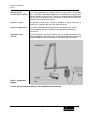
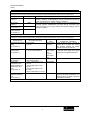
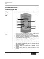
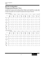
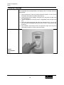
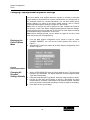
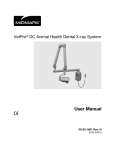
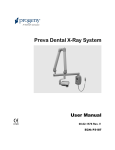
Operating Instructions Preva Exposure Settings When the system is powered on, the operator panel, Figure 2, displays the exposure settings (kV, mA, and seconds) for the currently selected tooth, image receptor type, and patient size. Use the Tooth Selection, Image Receptor Type, and Patient Size buttons to select other exposure settings. For a table of the factory-programmed exposure settings, refer to the Preprogrammed Exposure Settings tables on page 19 in this manual. Adjusting Exposure Settings Preset exposure settings can be adjusted prior to making an exposure. Use the right arrow to select the exposure setting to adjust. Then use the up and down arrow buttons to adjust the value. To save new presets, use System Configuration Mode described on page 21 in this manual. Exposure Button and Ready Indicator The Exposure button is used to initiate an X-ray exposure. For a complete exposure, the button must be pressed and held until the Radiation Indicator no longer illuminates and the audible signal is no longer heard. Releasing the Exposure button immediately terminates the X-ray exposure. CAUTION! Releasing the Exposure button prior to the completion of the X-ray exposure will result in an incomplete exposure of the image. This may require the operator to re-take the radiograph. When a premature release of the Exposure button occurs, the system will notify the operator momentarily and then return to operating mode. Ready Indicator The Ready Indicator illuminates when the system is ready to make an exposure. Immediately after an exposure, the Ready Indicator flashes until the X-ray tube cools down sufficiently to make the next exposure. When the Ready Indicator is flashing, no exposure can be made. Radiation Indicators The Preva has a visible and an audible Radiation Indicator. When an exposure is in progress, the Radiation Indicator on the Operator Panel is illuminated and an audible tone is heard. The exposure is complete when the Radiation Indicator is extinguished and the audible tone is no longer heard. 11 Operating Instructions Preva Taking an X-ray 1. 2. 3. 4. 5. 6. 7. 8. Turn the power switch, located at the upper right of the Control Unit, to the “On” position. The Ready Indicator on the front of the Operator Panel, (Figure 2), will light. Verify that the unit is set for the correct Image Receptor Type. The icon for the currently selected Image Receptor Type is illuminated. To change the Image Receptor type, press the Image Receptor Type button until the correct Image Receptor Type is selected. Verify that the system is set for the appropriate Patient Size. The icon for the currently selected Patient Size is illuminated. To change the Patient Size, press the Patient Size button until the correct Patient Size is selected. Verify that the unit is set for the Tooth to be imaged. The icon for the currently selected Tooth is illuminated. To change the Tooth Selection, press the Tooth Selection button until the correct Tooth is selected. If desired, preset exposure settings for the combination of Image Receptor Type, Tooth Selection, and Patient size, selected in steps 2-4, can be adjusted prior to making an exposure. Use the right arrow to select the exposure setting to adjust. Then use the up and down arrow buttons to adjust the value. Skip this step if you are using preprogrammed exposure settings. Note: When exposure settings are being adjusted, the Tooth Selection, Image Receptor Type, and Patient Size buttons are turned off. Position the Tubehead to the patient using standard accepted positioning procedures. Press and hold the Exposure button until the audible signal is no longer heard and the Radiation Indicator is no longer illuminated. Releasing the Exposure button or coil-cord hand switch at any time will immediately terminate the exposure. Note: When using the coil-cord hand switch, it is recommended that the operator exit the operatory if possible. Note: In order to comply with regulations and good safety practices, the technique factors must be visible to the operator from the remote location. Return the Tubehead to the storage position. Note: Be careful not to strike the Tubehead on anything when returning it to the storage position. It may be necessary to increase or decrease the kV, mA, or time from the preset values for one exposure. To do so: 1. 2. 3. 4. Press the Enter button to highlight the value to change. Use the up or down button to increase or decrease the value (no lights on the display will be lit to indicate the preset values). Press the Exposure button. Press any other button (Tooth, Film or Patient Size) to return the display to the preset values. 12 Operating Instructions Preva Using the 30 mm Cone (30-A2200) The Preva Dental X-ray System is factory set for use with the standard supplied 8 inch [20 cm] Cone. The 12 inch [30 cm] Cone [30-A2200] is available. Using the longer cone requires longer exposure times. See the System Configuration section on page 19 of this manual for instructions to set the system to use the longer cone. 13 Recommended Maintenance Preva Recommended Maintenance Regular Maintenance In the interest of equipment safety, a regular maintenance program must be established. This maintenance program should consist of annual system function checking. It is the owner’s responsibility to arrange for this service and to assure that the personnel performing this are fully qualified to service Midmark Corporation X-ray equipment. Cleaning and Disinfecting Cleaning / Disinfecting Employ personal protective equipment to prevent the spread of infections. Clean the outside of the system using a damp towel or non-alcohol based disinfectant. CAUTION: • Do not allow liquids to drip into the system electronics. • Do not spray cleaner or disinfectant directly onto the machine. • Protect the system from contamination using barriers available from dental distributors. • Follow the disinfectant manufacturer’s recommendations when using their cleaner or disinfectant. Cleaning Methods If not using a barrier, between each patient, perform the following cleaning and disinfecting steps. 1. Remove gross bio-burden from the cone, handles and structure with a disposable towel moistened with water. 2. Dry the cone, handles and structure with disposable towels. 3. Wipe the cone, handles and structure with a germicidal broad spectrum disinfectant product following the disinfectant manufacturer’s instructions. 4. Clean any remaining disinfectant residue from the system with a disposable towel moistened with water. This additional step prevents possible product discoloration or corrosion. 5. Dry the cone, handles and structure with paper towels. Caution! The Preva Dental X-ray System is not waterproof. Use only moistened, not saturated, towels. 14 Checking System Functions Preva Checking System Functions The following checks must be performed to complete the installation of the Preva Dental X-ray System and as part of the recommended maintenance as indicated in the User Manual. Failure to perform these checks may result in an installation that does not comply with U.S. Radiation Performance Standards 21 CFR Subchapter J. CAUTION! If the Preva Dental X-ray System does not perform the functions below the system is not to be used. See the Troubleshooting section of the Installation Guide or contact Midmark Corporation’s Technical Support. 15 Checking System Functions Preva System Function Checklist Wall Mounting Ensure that the wall support is adequate and that the system is properly mounted to the wall. Labels Ensure that all certified components bear labels that include the model and serial number, date of manufacture and a statement of certification as noted elsewhere in this manual. Tubehead Check for oil leaks or other evidence that could indicate internal damage. Replace the Tubehead, if necessary. Tubehead Rotation Ensure that the Tubehead maintains its position around the horizontal axis while remaining easy to rotate and position. Also check the vertical pivot of the Tubehead for easy movement while remaining in position after moving. Suspension Check that all movements are smooth and quiet. Verify that the Tubehead is properly counterbalanced for vertical drift and that the Horizontal and Articulating Arms do not drift horizontally. Power Switch Verify that the switch is working properly and that the Ready Indicator is illuminated when the power switch is in the ON position. Operator Panel Controls With the power switch, located at the upper right of the Control Unit, in the ON position, verify that technique factors appear on the Operator Panel. Also, check the function of the selection buttons for Tooth Selection, Image Receptor Type and Patient Size. Pressing a selection button should cause indicator lamps to indicate the selected item. Exposure Button Verify that the Exposure button on the Operator Panel is functioning properly. To make an exposure, press and hold the Exposure button until the Radiation Indicator is extinguished and the audible signal is no longer heard. Exposure Indicators Make several exposures and verify that the Radiation Indicator illuminates and the audible signal is heard. Premature Termination Select the longest exposure time possible using the up and down arrows. Initiate an exposure but release the Exposure button after a brief period of time before the timer terminates the exposure. Verify that the display indicates “Pretermination Error” and returns to normal operating mode. Coil-cord Hand Switch Option If a coil-cord hand switch is used, inspect the switch housing and coil cord for damage or wear. Replace if evidence of damage is present. User Information Make certain that the user of the system has received the User Manual. 16 Checking System Functions Preva New Tube Seasoning Procedure X-ray tubes that sit dormant for several months can become electrically unstable. To remedy this condition, it is recommended you perform a new tube seasoning procedure. This process establishes stable high voltage operation and will ultimately extend the life of the tube. Repeat this procedure before returning to normal operation any time the system has been unused for more than two months. 1. Verify system operation. 2. Energize the system. 3. Select 60 kilovolts [kV], 7 milliamperes [mA], and the exposure time of one second. 4. Make five exposures at this level, observing the normal cooling time. 5. Select 65 kilovolts, 7 milliamperes, and the exposure time of one second. 6. Make five exposures at this level, observing the normal cooling time. 7. Select 70 kilovolts, 6 milliamperes, and the exposure time of one second. 8. Make five exposures at this level, observing the normal cooling time. 17 Solving Performance Issues Preva Solving Performance Issues Performance Issues Light or Dark X-ray Images 1. Adjust the selected exposure time, kilovoltage [kV] or tube current to produce an acceptable image. If necessary, reprogram the technique factors, as explained in the System Configuration section on page 19 of this manual. 2. Verify the kilovoltage and tube current during an exposure using the diagnostic mode, as explained in the System Configuration section (pg. 19) of this manual. Alternatively, you may employ a non-invasive meter to evaluate kilovoltage and exposure time. 3. Inspect the condition of the remaining imaging chain components such as the film, chemistry and processor, or the condition of the X-ray sensor and computer. No X-ray If no X-ray is produced, check the following: 1. Verify that the line cord (if one is in use) is properly connected. 2. Verify that the power switch is in the ON position. Pre-termination Error Early release of the exposure switch will cause a pre-termination error to occur. After five seconds, the system will return to the normal operating condition. Be advised that this will result in an underexposed image. Obtaining Technical Support If the above steps do not resolve any of the error issues that you are experiencing, suspend use of the Xray unit and contact Midmark Technical Support for assistance. Contact Midmark Corporation 675 Heathrow Dr. Lincolnshire, Illinois 60069 U.S.A. Phone: 1-800-MIDMARK Fax: 847-415-9801 [email protected] 18 System Configuration Preva System Configuration Preprogrammed Exposure Times The tables below show the factory default exposure settings for each combination of Tooth, Image Receptor Type, and Patient Size on the Operator Panel. These exposure settings can be modified using the System Configuration mode. See System Configuration Mode on page 21 for details. 19 System Configuration Preva Changing Language Five languages are preprogrammed in the display panel. To change follow the steps below. 1. Push and hold the Tooth and Patient selection switches, a menu screen will appear after about 5 seconds. (See Figure 3) 2. Using the down arrow highlight “Configure Unit” and press the right arrow key. (See Figure 3) 3. “Select Languages” on the next screen is highlighted press the right arrow key. 4. Select the desired language and press the right arrow key. If you do not see your desired language listed arrow down to “More” and press the right arrow key. 5. After selection arrow down to Exit and press the right arrow key then repeat this procedure to return to the main screen. Figure 3 Preva Operator Panel 20 System Configuration Preva System Configuration Mode About System Configuration Mode The Preva Dental X-ray System has a software-driven system configuration mode. When the Preva is in system configuration mode, you can perform the following procedures: • Adjusting the Display • Changing Preprogrammed Exposure Settings • Changing the Cone Size • Showing Current System Configuration • Displaying Diagnostic Data Using System Configuration Mode 1. To enter system configuration mode, depress the Tooth Selection and Patient Size Selection buttons on the Operator Panel simultaneously for 5 seconds. The display shows the Main System Configuration menu, as shown in Figure 4, and the Ready Indicator blinks. 2. To select menu items while in system configuration mode, use the up and down arrows to highlight a menu option. Then use the right arrow button as an Enter button to select the highlighted option. When changing presets, the right arrow button is also used to select the technique factor. 3. After selecting a menu option, use the up and down arrows to increase or decrease values. Figure 4 Main System Configuration Menu 21 System Configuration Preva Adjusting the Display The Preva Dental X-ray System allows the operator to adjust the display image. 1. From the system configuration main menu, shown in Figure 4, select ADJUST DISPLAY. You will see the Display Options menu shown in Figure 5. 2. Selecting EXIT returns the display to the Main System Configuration menu shown in Figure 4. ® Adjusting Contrast 1. Select ADJUST CONTRAST from the menu. You will see the Progeny logo. 2. Use the up and down arrows to increase or decrease the contrast between the menu text and the display background. 3. Press the right arrow to save your settings. Reversing the Image 1. Select REVERSE IMAGE from the menu. The text and display background colors will be swapped. 2. Press the right arrow to save your settings. Figure 5 Display Options Menu 22 System Configuration Preva Changing Preprogrammed Exposure Settings The Preva Dental X-ray System allows the operator to increase or decrease image density for all presets for a receptor simultaneously or to change each of the technique factors for a preset individually. You can also restore factory default settings. For charts of the factory default settings, refer to Factory Preprogrammed Exposure Settings on page 19 in this manual. Note: If the 12 inch [30 cm] cone is going to be used, configure the Preva for use with the 12 inch cone before changing preprogrammed exposure settings. Configuring the Preva for use with the 12 inch cone will reset exposure settings to the default settings used with the 12 inch cone. Note: Before changing presets, use the tables on pages 25 and 26 to write down the presets you are programming. Displaying the Preset Options Menu 1. From the Main System Configuration menu, shown in Figure 4, select CHANGE PRESETS. You will see the Preset Options menu shown in Figure 6. 2. Selecting EXIT returns the display to the Main System Configuration menu shown in Figure 4. Figure 6 Preset Options Menu Changing All Receptor Settings Globally 1. Select ALTER DENSITIES from the Preset Options menu. The first Image Receptor Type illuminates. The display shows the selected Image Receptor Type and current density. 2. Using the Image Receptor Type button, select the image receptor to adjust. 3. Use the up and down arrow buttons to specify a percentage by which densities will be increased or decreased for the selected receptor. Densities can be increased or decreased according to values provided on the display. 4. Press Enter to save your settings. 23 System Configuration Preva Preprogramming 1. Turn the system on. to Digital Sensors 2. Push and hold the Tooth and Patient selection switches, a menu screen will appear after about 5 seconds. 3. Select CHANGE PRESETS from the Menu Options screen. 4. Select SELECT RECEPTOR from the Preset Options menu (Figure 6). 5. Press the up or down button to highlight the sensor or phosphor plate to change, and press Enter. 6. Select YES or NO on the Verification screen. 7. Exit the Preset Options menu. 8. Exit the Menu Options menu. A message of “Saving Settings” will display briefly, and then the system will return to the normal operational mode. Note: When you are working in service mode, the green light next to the exposure button will blink. Changing Presets Individually 1. Turn the system on. 2. Push and hold the Tooth and Patient selection switches, a menu screen will appear after about 5 seconds. 3. Select EDIT PRESETS from the Preset Options menu. The display notifies you that you are entering Edit Preset Mode, and Tooth Size, Image Receptor Type, and Patient Size are illuminated. 4. Use the Tooth Selection, Image Receptor Type, and Patient Size Selection buttons to select the preset to change. The display shows the current values for the preset. 5. Use the right arrow button to highlight the technique factor (tube voltage in kilovolt [kV], tube current in milliamp [mA] or duration in seconds [s]) to change. 6. Use the up and down arrow buttons to set the value for the selected technique factor and preset. 7. Repeat steps 2-4 to change additional presets. 8. When you have completed all changes, press the Tooth Selection and Patient Size Selection buttons simultaneously for 5 seconds to record the change. Recall Presets 1. Turn the system on. 2. Push and hold the Tooth and Patient selection switches, a menu screen will appear after about 5 seconds. 3. To return all presets to factory defaults, select RECALL PRESETS from the Preset Options menu. The menu will ask you to confirm your choice. 4. Select YES using the up arrow button and return all presets to factory default settings. Selecting YES will erase any custom presets that have been set up. 5. Select NO using the down arrow button and retain current presets. 24 System Configuration Preva Record Your Exposure Settings (8” [20 cm] Cone) If the preprogrammed exposure settings do not produce the density desired, adjust the settings using System Configuration mode. Record your settings in the table below. 8 inch (20 cm) Cone Tooth Selection Incisor Setting Digital Receptor D-speed Film Adult Child kV mA seconds Bicuspid kV mA seconds Bitewing kV mA seconds Lower Molar kV mA seconds Upper Molar kV mA seconds 25 Adult Child E/F Speed Film Adult Child System Configuration Preva Record Your Exposure Settings (12” [30 cm] Cone) If the preprogrammed exposure settings do not produce the density desired, adjust the settings using System Configuration mode. Record your settings in the table below. 12 inch (30 cm) Cone Tooth Selection Incisor Setting Digital Receptor D-speed Film Adult Child kV mA seconds Bicuspid kV mA seconds Bitewing kV mA seconds Lower Molar kV mA seconds Upper Molar kV mA seconds 26 Adult Child E/F Speed Film Adult Child System Configuration Preva Showing Current System Configuration The Preva Dental X-ray System displays the current system configuration. This display is informational only. 1. From the Main System Configuration menu, shown in Figure 4, select CONFIGURE UNIT. You will see the Configuration menu shown in Figure 7. 2. Select SHOW CONFIG. The display will show: • Current software version • Cone size • Diagnostic mode on or off 3. Press any button on the Operator Panel to return to the Configuration menu. Figure 7 Configuration Menu 27 System Configuration Preva Changing the Cone Size Selecting SET CONFIG. from the Configuration menu, shown in Figure 7, displays the Set Configuration menu, Figure 8, with options to change the cone size. The Preva Dental X-ray System is factory set for use with the standard supplied 8 inch [20 cm] Cone. The 12 inch [30 cm] Cone [30-A2200] is available. Using the longer Cone requires longer exposure times, which the Preva automatically selects when you change the Cone size in the Set Configuration menu. Using a 12 inch [30 cm] Cone 1. From the Main System Configuration menu, shown in Figure 4, select CONFIGURE UNIT. You will see the Configuration menu shown in Figure 7. 2. Select SET CONFIG. You will see the Set Configuration menu, shown in Figure 8. 3. From the Set Configuration menu, use the up and down arrows to highlight 12” CONE SIZE. 4. Press the right arrow button to select the 12” CONE. The display warns you that selecting the 12 inch Cone will override custom presets with the default factory settings for the 12 inch Cone. 5. Using the up arrow, select YES to install presets for the 12 inch Cone. Figure 8 Set Configuration Menu 28 System Configuration Preva Diagnostic Mode The Preva Dental X-ray System has a diagnostic mode in which you can display About Diagnostic Mode a summary of maintenance data or display feedback values after each exposure. Showing the Maintenance Summary 1. From the Main System Configuration menu, shown in Figure 4, select CONFIGURE UNIT. You will see the Configuration menu shown in Figure 7. 2. Select SET CONFIG. You will see the Set Configuration menu, shown in Figure 8. 3. To display a summary of maintenance data, highlight select SHOW MAINT from the Configuration menu. The following maintenance data are displayed: • Total kJ (kilojoules—total system heat on X-ray tube) • Exposure Count • Reboots (power up cycles) • OT Counts (over-threshold counts) 4. Press any button on the Operator Panel to return to the Configuration menu. Showing Feedback Values After an Exposure If you take an X-ray (follow the Steps on page 12 to take an X-ray) while in diagnostic mode, the display shows feedback values for that exposure. Until you exit diagnostic mode, the display will continue to show feedback values after each exposure. 1. From the Main System Configuration menu, shown in Figure 4, select CONFIGURE UNIT. You will see the Configuration menu shown in Figure 7. 2. Select SET CONFIG. You will see the Set Configuration menu, shown in Figure 8. 3. From the Set Configuration menu, use the up and down arrows to highlight DIAG MODE ON. Press the right arrow button to turn on diagnostic mode. 4. Exit System Configuration mode by highlighting and selecting EXIT in the Configuration and Main menus. 5. Take an X-ray. The display will show the following feedback values: • kV • mA • Filament current 6. Press any button on the Operator Panel to clear the feedback values from the display. 7. To exit diagnostic mode, depress the Tooth Selection and Patient Size Selection buttons simultaneously for 5 seconds to display the Main System Configuration menu. From the Main System Configuration menu, highlight and select CONFIGURE UNIT. Then highlight and select SET CONFIG. On the Set Configuration menu, highlight and select DIAG MODE OFF. 29 Specifications Preva Specifications Preva Dental X-ray System Line Voltage AC 100 V to 250 V, 50 Hz or 60 Hz Line Load 250 V, UL Recognized – It is recommended that branch circuit does not exceed 15A Tube Potential 60 kV, 65 kV, 70 kV Tube Current 4 mA, 5 mA, 6 mA, 7 mA (7 mA is not available at 70 kV.) Irradiation Time 20 ms through 2 s Minimum Source to Skin Distance 8 inch (20 cm) 12 inch (30 cm) Focal Spot 0.4 mm (per IEC 60336) Operating Temperature +50 °F to +95 °F (+10 °C to +35 °C) Storage Temperature -31 °F to +150 °F (-35 °C to +66 °C) Maximum Altitude 12,000 ft (3,657 m) X-ray Beam Dimension Diameter of 2.72 inches (7 cm) at the end of the 7 inch Cone. Cones with smaller diameter or rectangular beams are available. Humidity Range (Operation & Storage) 10 to 80 % non-condensing 30 Specifications Preva Statements and Information According to 21 CFR Sub Chapter J 1020.30 (h) (1) (i) Instructions for the use of the Preva and precautionary statements are part of this User’s Manual. 1020.30 (h) (1) (ii) As described in the Recommended Maintenance section, the Preva should be serviced on an annual basis to ensure proper functionality. It is the owner’s responsibility to arrange for this service and to assure that the personnel performing this service are fully qualified to service Midmark Corporation X-ray equipment. 1020.30 (h) (2) (i) Leakage technique factors: 70 kV, 0.4 mA Minimum filtration (half-value layer) in useful beam: 1.7 mm Al equivalent at 70 kV 1020.30 (h) (2) (ii) The cooling curve charts for the anode can be found on page 32. Please note that due to the integrated design of the Preva, there is no meaningful separate cooling curve for the tube housing. 1020.30 (h) (2) (iii) Since the Preva operates as a complete system in only one mode as a high frequency X-ray system, there is no need to provide a tube rating chart. 1020.30 (h) (3) (i) Rated nominal line voltage: 110 V – 230 V Line voltage regulation: 10% of the nominal line voltage 1020.30 (h) (3) (ii) and (iii) The maximum momentary line current (less than 5 s) of the Preva is 10 A when operated on 120 V (1.2 kW). Operation at higher input voltage will reduce the maximum current (5 A at 240 V). The technique factors producing the maximum momentary line current are 65 kV, 7 mA, 2 s. 1020.30 (h) (3) (v) Generator rating at maximum technique factor of 65 kV, 7 mA is 455 W. Duty cycle is 1:15. 1020.30 (h) (3) (vi) Maximum deviation from indicated values: a) Peak tube potential, maximum deviation: ±5% b) Tube current, maximum deviation: ±1 mA c) Exposure time: min 20 ms, max. 2 s, max. deviation: ±5%+1 ms 1020.30 (h) (3) (viii) The measurement criteria for all technique factors used in paragraphs (h) (3) (iii), and (h) (3) (vi) is 90% of the selected peak tube voltage. 31 Specifications Preva Thermal Characteristics Charts Figure 9 Toshiba Tube Rating Chart Figure 10 Kailong Tube Rating Chart Thermal Characteristics Chart 32