1
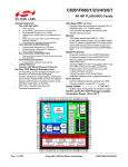
Freescale Semiconductor, Inc.
Electrical and Thermal Characteristics
Table 9. Processor Bus AC Timing Specifications (continued)
At recommended operating conditions. See Table 4.
All Speed Grades
Symbol2
Parameter
Freescale Semiconductor, Inc...
SYSCLK to ARTRY/SHD0/SHD1 high impedance after
precharge
tKHARPZ
Min
Max
—
2
Unit
Notes
tsysclk
5, 8,
9, 10
Notes:
1. All input specifications are measured from the midpoint of the signal in question to the midpoint of. the rising edge
C of SYSCLK to
of the input SYSCLK. All output specifications are measured from the midpoint of the rising N
edge
I
the midpoint of the signal in question. All output timings assume a purely resistive 50-Ω load
(see
Figure 4). Input
,
R
and output timings are measured at the pin; time-of-flight delays must be added for trace
lengths,
vias, and
O
T
connectors in the system.
UC
2. The symbology used for timing specifications herein follows the pattern of t(signal)(state)(reference)(state)
for inputs
D
and t(reference)(state)(signal)(state) for outputs. For example, tIVKH symbolizesN
the time input signals (I) reach the valid
O or input setup time. And tKHOV
state (V) relative to the SYSCLK reference (K) going to the high (H)C
state
I
symbolizes the time from SYSCLK(K) going high (H) until outputs
M(O) are valid (V) or output valid time. Input hold
time can be read as the time that the input signal (I) went invalid
SE (X) with respect to the rising clock edge (KH)
(note the position of the reference and its state for inputs)
LEand output hold time can be read as the time from the
rising edge (KH) until the output went invalid (OX). A
3. The setup and hold time is with respect to the rising
SC edge of HRESET (see Figure 5).
E
4. This specification is for configuration mode E
Rselect only.
5. tsysclk is the period of the external clockF(SYSCLK)
in nanoseconds (ns). The numbers given in the table must be
multiplied by the period of SYSCLK Y
to compute the actual time duration (in ns) of the parameter in question.
B
6. Mode select signals are: BVSEL,
L3VSEL, PLL_CFG[0:3], PLL_EXT, BMODE[0:1].
D
E
7. According to the bus protocol,
IV TS is driven only by the currently active bus master. It is asserted low then
precharged high beforeHreturning to high impedance as shown in Figure 6. The nominal precharge width for TS is
C than the minimum tSYSCLK period, to ensure that another master asserting TS on the
0.5 × tSYSCLK, i.e.,R
less
A
following clock will not contend with the precharge. Output valid and output hold timing is tested for the signal
asserted. Output valid time is tested for precharge.The high impedance behavior is guaranteed by design.
8. According to the bus protocol, ARTRY can be driven by multiple bus masters through the clock period
immediately following AACK. Bus contention is not an issue because any master asserting ARTRY will be driving
it low. Any master asserting it low in the first clock following AACK will then go to high impedance for one clock
before precharging it high during the second cycle after the assertion of AACK. The nominal precharge width for
ARTRY is 1.0 tsysclk; that is, it should be high impedance as shown in Figure 6 before the first opportunity for
another master to assert ARTRY. Output valid and output hold timing is tested for the signal asserted.The
high-impedance behavior is guaranteed by design.
9. According to the MPX bus protocol, SHD0 and SHD1 can be driven by multiple bus masters beginning the cycle
of TS. Timing is the same as ARTRY, i.e., the signal is high impedance for a fraction of a cycle, then negated for
up to an entire cycle (crossing a bus cycle boundary) before being three-stated again. The nominal precharge
width for SHD0 and SHD1 is 1.0 tsysclk. The edges of the precharge vary depending on the programmed ratio of
core to bus (PLL configurations).
10. Guaranteed by design and not tested.
Figure 4 provides the AC test load for the MPC7450.
Output
Z0 = 50 Ω
RL = 50 Ω
OVDD/2
Figure 4. AC Test Load
MOTOROLA
MPC7450 RISC Microprocessor Hardware Specifications
For More Information On This Product,
Go to: www.freescale.com
17


![PC755BM8 [Preliminary]](http://vs1.manualzilla.com/store/data/005786860_1-ac3ee01c2b00aeb18fc7f0a57a841c91-150x150.png)