1
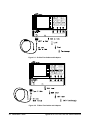
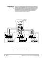
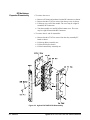
The Agilent E1473A RF Multiplexer Expander Module can be inserted in a
C-Size VXI bus mainframe next to the multiplexer, or can be located up to
eight meters away from the multiplexer using remote expander cables.
Locating the expander module close to the external device keeps connecting
cable lengths to a minimum, thereby reducing the possibility of cross-talk
and insertion loss of high frequency signals.
Agilent
E1474A/E1475A
Description
The Agilent E1474A 75 Ohm RF Multiplexer and the Agilent E1475A 75
Ohm RF Multiplexer Expander are identical in operation to the Agilent
E1472A/E1473A described earlier in this chapter with the exception of the
characteristic impedance of the RF channels.
Inputs and outputs for either module use special 75 Ohm SMB connectors.
The special connectors and their mating connectors are listed in the Agilent
E1474A/E1475A RF Multiplexer/Expander User’s Manual.
Multiplexer/
Expander
Specifications
Specifications are listed in Appendix A of the Agilent E1472A/E1473A RF
Multiplexer/RF Multiplexer Expander User’s Manual and the Agilent
E1474A/E1475A RF Multiplexer/RF Multiplexer Expander User’s Manual.
These specifications are the performance standards or limits against which
the modules may be tested.
Multiplexer/
Expander
Serial Numbers
Devices covered by this manual are identified by a serial number prefix
listed on the title page. Agilent Technologies uses a two-part serial number
in the form XXXXAYYYYY, where XXXX is the serial prefix, A is the
country of origin (A=USA), and YYYYY is the serial suffix. The serial
number prefix identifies a series of identical instruments. The serial number
suffix is assigned sequentially to each instrument. The serial number plate
is located on the right-hand shield near the backplane connectors.
Agilent E1472A/73A/74A/75A Service Manual
General Information 19