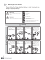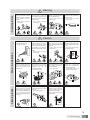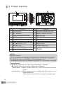
1
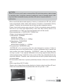
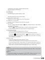
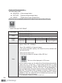
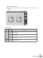
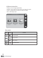
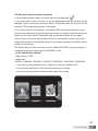
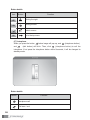
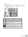
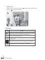
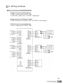
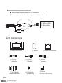
User Manual
Color video door phone CDV-70UM
• Thank you for purchasing COMMAX products.
• Please carefully read this User’s Guide (in particular, precautions for safety) before using a product and follow
instructions to use a product exactly.
• The company is not responsible for any safety accidents caused by abnormal operation of the product.
Greetings
● Thank you for choosing COMMAX.
● Please read this manual carefully before you use the product.
Table of contents
Greetings ..................................................................................................................1
Contents table ...........................................................................................................1
1. Warnings and caution ...........................................................................................2
2. Product Overview..................................................................................................4
3. How to use this product .......................................................................................6
4. GUI Function .....................................................................................................12
5. Wiring methods ...................................................................................................31
6. Components .......................................................................................................32
7. Caution in use ....................................................................................................33
8. Miscellaneous .....................................................................................................33
9. Specification........................................................................................................33
1
1. Warnings and caution
Please follow the things described below in order to prevent any
danger or property damage.
Prohibition.
Warning
No disassembly
It may cause a serious damage or injury if
violated.
No touch
Caution
Must follow strictly.
It may cause a minor damage or injury if violated.
Shows plugging out the power cord
without an exception
Shows the warning and caution for an electric shock.
Shows the warning and caution for a fire.
Power & Installation
Warning
2
Please dont use several
products at the same time on
one power socket.
It may cause a fire due to an
abnormal overheating.
Please dont bend the power
cable excessively or it may
cause an electric shock.
fire when using a damaged
power cable.
Please dont handle the power
cable with a wet hand.
It may cause an electric
shock.
Please plug out the power
cable from the socket when
not using it for a long period
of time.
It may shorten the product
lifespan or cause a fire.
Please dont install the
product in the place where
there is much oil, smoke or
humidity.
It may cause an electric
shock or fire.
Please dont install the
product with the lightening
and thunder.
It may cause an electric
shock or fire.
Please dont use and connect
this product with other
products with different rated
voltage
It may cause a disorder or
fire.
When installing the product
that generates heat, please
install the product away from
the wall (10cm) for the
ventilation.
It may cause a fire due to
the increased internal
temperature.
Cleaning & Use
Warning
Please dont disassemble,
repair or rebuild this product
arbitrarily (please contact the
service center if a repair is
needed.
It may cause an electric
shock or fire.
If an abnormal sound, burning
smell or smoke is coming out
of the product, please plug out
the power cable and contact a
service center.
It may cause an electric
shock or fire.
Please dont insert any
metallic or burnable materials
into the ventilation hole.
It may cause an electric
shock or fire.
Please use only the designated
batteries for the products of
using DC power.
It may cause an electric
shock or fire.
Cleaning & Use
Power & Installation
Caution
Please plug the power cable
firmly into the inner end
It may cause a fire.
Please hold the plug tightly
when unplugging the power
cable (a part of the copper
wire may be disconnected if
the grabbing is only made on
the cord when pulling out the
cable).
It may cause an electric
shock or fire
When connecting the power
cables after cutting the cable,
please install the product with
power off
It may cause an electric
shock or fire
Please be careful when using
an AC circuit breaker since
there is a possibility of an
electric shock.
Please check the use voltage
and current for the DC-only
products and use the
appropriate rectifier.
It may cause a fire.
Please avoid direct rays of the
sun or heating devices at a
time of installation.
It may cause a fire.
When cleaning the product,
please rub it with a soft and
dry cloth after plugging out
the power cable. (Please dont
use any chemical products
such as wax, benzene, alcohol
or cleanser.)
Please dont drop the product
on the ground and dont apply
a shock .
It may cause a failure.
Please use the designated
connection cable within the
maximum calling distance
designated for the product
It may reduce the product
performance.
When installing the product,
please fix it firmly while using
the wall-mounting unit and
screws.
It may cause an injury from
the falling object.
Please dont install the
product on an unstable place
or small support board.
It may cause an injury if it
falls down while in use.
3
2. Product Overview
No.
Description
No.
Description
1
LCD MONITOR
11
RECEIVER VOLUME CONTROL
2
LEFT SPEAKER
12
RINGER VOLUME CONTROL
3
POWER AND MOOD LIGHTING
13
MENU BUTTON
4
MICROPHONE
14
SELECT BUTTON
5
RIGHT SPEAKER
15
UP BUTTON
6
MONITOR BUTTON
16
DOWN BUTTON
7
INTERPHONE BUTTON
17
POWER ON/OFF
8
TALK BUTTON
18
T-FLASH CARD SLOT
9
IMAGE SAVE BUTTON
10 DOOR RELEASE BUTTON
19
EXTERNAL CONNECTION
TERMINAL
[NOTE]
Setting for Camera
You can set whether use camera or not using short pin on the back of the product.
You should set to use only CAMERA 1 with connecting short pin.
(Connecting Short Pin: use only Camera1/ open Short Pin : Use Camera1, Camera2)
[Format function]
Please press 2 seconds on the right of the products Menu + Down()
"Format SD card? Push the key Yes[Select] or No[Menu]"
: [Menu] Button When screen turned off, it will be changed the standby
mode.
[Select] Button When screen show up ' please wait, SD Format it wii be
progressed format.
When melody finished it will be changed the standby mode.
4
Caution
Please, do not turn on/off, insert or remove Micro SD card during saving, capture image
or recording video. It might be caused of malfunction, harm or damage goods. (User
may lose data in embedded memory and Micro SD card or it may be reason of
malfunction)
• When memorized data exceed capacity of memory in external micro SD card, product
erase automatically delete oldest data because of limitation of embedded memory
capacity. Therefore, we recommend user do back-up data to separate memory.
• Please, check bellow memory spec and use it. We do not guarantee proper operation
and we are not under legal responsibility if user uses other memory which is not
recommended by us. When you insert card please insert until the sounds.
• Recommended spec. of MICRO SD [T-FLASH] Card
(Please, format memory first before use it)
1) Manufacturer : SANDISK
MICRO SD : 2GByte
MICRO SDHC [CLASS 4] : 4 ~ 16GByte
2) Manufacturer : TRANSCEND
MICRO SD : 2GByte
MICRO SDHC [CLASS 4] : 4 ~ 16GByte
• This product has ‘ SUPERCAP inside.
‘SUPERCAP’ is for preventing data lost and damaged in memory if there is
temporarily black out or lost electric power. It turns on embedded clock in period time
when product lost power. Recharging ‘ SUPERCAP’ takes over 30minutes after
turning on power. It can operate embedded clock during approximately 24hours
without external power. If data file is many or size of file is big, embedded clock may
stop within 48hours. Therefore, user must check and set time in product when turning
on product again.
• We recommend check time in product periodically because of time error or difference
time.
• How to insert Micro SD [T-FLASH]
Please, refer to below photo and pay attention to direction when Insert Micro SD card.
When user inserts Micro SD card, please slide card until you feel a ‘ click’
5
3. How to use this product
3-1. Stand-by mode
① When you turn on the video phone, The LED(Blue) on the bottom of LCD Display will
be turned on. And then you can see a LOGO on the LCD screen, after booting
sound, it will be stand-by mode.
② You can check model name and version information by pressing DOWN button on
the right for 2 seconds in stand-by mode.
3-2. Operation
(1) To make a call
① When the visitor press button in stand-by mode from the entrance(door camera),
electronic chime bell rings of video phone and interphone.
And LEDs of
(monitor button) and
(talk button) blink, the image of the visitor
is shown on the screen in 3 seconds. (If you press menu button, it will be
disconnected and turned into stand-by mode)
② The screen will be turned on for 30 seconds in stand-by mode and for
communication, it will be turned on for 60 seconds.
③ If you call interphone by pressing
(talk button) and push
(interphone button)
for 3 seconds, ringtone will come out from interphone and the conversation begins if
you pick up the hand set. Press talk button to end the conversation.
④ In order to call video phone from interphone, pick up the handset of interphone and
press call button. The LED of
(interphone button) and
(talk button) will blink,
ringtone will come out from the video phone and the image of interphone will also
blink and off on the screen. Then, the
will blink. If you click
begins. If
(interphone button) and
(interphone button) or
(interphone button) or
(talk button)
(talk button), the conversation
(talk button) are not clicked, the monitor will
return to standby mode.)
(2) VOLUME CONTROL (DOWN UP)
① Adjust volume of receiver sound with receiver volume control on the side of the
video phone from "small" to "loud" .
② Adjust volume of ringer volume with ringer volume control on the side of the video
phone from "small" to "loud".
(3) Video format (NTSC/PAL) setting
Video format between both of CCTV and CAMERA should be same.
a) In case of connecting CCTV(NTSC)
Push SELECT+UP buttons on side at the same time for a few seconds, it will be
changed to NTSC mode.
6
b) In case of connecting CCTV(PAL)
Push SELECT+DOWN buttons on side at the same time for a few seconds, it will be
changed to PAL mode.
Caution : If you change video format, the stored image in SD CARD will be
deleted.
Initialization method and changing list
a) SIDE KEY Initialization(factory initialization)
- NTSC(SELECT+UP),PAL(SELECT+DOWN)
- Color balance (BRIGHT 50/CONTRAST 50/COLOR 50)
- Language(English)
- Auto-save function (Auto-save)
- Image save mode (Still image)
- Digital album visual effects (None)
- Digital album screen timeout (5minutes)
- Proximity sensors(disable)
- Deleted saved images of SD CARD
b) Initialization of settings(user initialization)
- Color balance (BRIGHT 50/CONTRAST 50/COLOR 50)
- Language(English)
- Auto-save function (Auto-save)
- Image save mode (Still image)
- Digital album visual effects (None)
- Digital album screen timeout (5minutes)
- Proximity sensors (disable)
- Deleted saved images of SD CARD.
(4) Call Function
① If you press
(monitor button) in stand-by mode, LEDs of
(talk button) blink. By pressing
(monitor button),
(talk button), you can talk with door camera.
By picking up the handset of interphone at this time, 3-way communication is
possible.
② You can talk for 60 seconds with door camera. When the time is over, it will be
stand-by mode automatically.
③ Click
(talk button) and
(interphone button) to call the interphone. If you pick
up the handset, the talk begins.
7
① It is possible to communicate with interphone for 60 seconds, You can also extend
more 60 seconds by pressing call button on the video phone or interphone. When
the time is over(60 seconds), it turns to stand-by mode automatically.
② You can talk with CAMERA2 by calling CAMERA2 during communicating with
CAMERA1, the screen will be sequentially shown from CMAERA1 to CAMERA2
when user press
(monitoring button).
③ When the visitor calls from the entrance(door camera) during communicating
between video phone and interphone, The LEDs of
(Monitoring button) and
(talk button) blink, 3-way communication is possible by pressing
button) or
(Monitoring
(talk button).
Press (talk button) to finish talking.
(5) Save image
① To save camera images, press (save image button) more than 1second during
calling camera or monitoring mode.
② You can save still image is shown on the screen when you press button.
③ While it is saving the video clip, save image buttons will not work. The button will
work after image saving is complete.
④ This function operates regardless of setting for recording method(Auto/manual)
⑤ You can use same function by pressing
(monitor button) for long when you call
camera or monitoring.
⑥ Images are stored in SD CARD only. If you don't put in SD CARD or use defected
SD CARD, saving images is not available.
(6) Monitoring
(The following scenario is the example that 2cameras and 2 CCTV are installed. If they
are not installed as like the example, the monitoring function of relevant camera doesn't
work.
- Monitoring sequence (The monitoring mode will be sequentially operated when user
presses
button as follows.)
(a) CAM1 (Full) + CCTV1 (PIP)
- No CCTV1 signal, transferred (b)
(b) CAM1 (Full)
(c) CCTV1 (Full)
- No CCTV1 signal, transferred (d)
(d) CAM2 (Full) + CCTV2 (PIP)
8
- If the short pin are inserted, switched stand-by mode.
- No CCTV2 signal, transferred (e)
(e) CAM2 (Full)
(f) CCTV2 (Full)
- No CCTV2 signal, switched stand-by mode
- Monitoring sequence during communicating
(a) CAM1 (Full) + CCTV1 (PiP)
- Condition: No CCTV1 signal, Only CA1 (Full) is shown.
(b) CAM2 (Full) + CCTV2 (PiP)
- Condition: No CCTV2 signal, Only CA2 (Full) is shown.
(7) Door release
- The door release works by pressing
(door release button) of video phone
during being on the phone.
- The LED
of (door release button) is turned on during releasing door.
(In case of being installed door camera with door release function)
(8) Save captured image
This function apply the storage method is "Picture"
If you set auto-save mode, it store image when there is call from camera.
If you press
(save image button) or
(monitor button) for 1second in
monitoring mode or communicating, 1 cut image will be stored after a recording
icon is displayed in the screen.
(9) Save of video
This function apply the recording method is "video".
It record image when there is a call from camera in auto-recording mode.
If you set auto-save mode, it record video for 30 seconds when there is call from
camera, and for 60 seconds in case of communicating. The maximum time able to
record video for one time is 90 seconds(reply time for call + time for talk)
caution 1
- Don't remove SD card during saving of captured image and video. It may cause
defect or data loss.
caution 2
- The recording image file is only stored in SD CARD. Please note that It is not
available to record image If SD CARD was defective or not put into product.
9
Folder and File management
Create basic folder
. \MOVIE\00\
(Video storage folder)
. \PICTURE
(Captured image storage folder )
. \ALBUM
(Digital album image storage folder)
When the icon is displayed, please built in data or back up into Micro SD card.
SAVE FILE and FILE FORMAT
Still image
Video
Details
of file
120916_130502_D1.jpg
120916_130502_C2.jpg
120916_130502_D1.mp4
120916_130502_C1.mp4
Date
Time
12 year 9
month 16 day
13hr5min2sec
Video Type
File Type
D1,D2 = Entrance 1, 2
Still image (*.jpg)
C1,C2 = CCTV 1,2
Video
(*.mp4)
It is need to keep minimum extra space of Micro SD Card Minimum
space : Micro SD - 100MByte
Save 128 cuts(MAX) of Captured images
If the memory exceed capacity, the oldest file will be deleted and
then save new file.
Video can be saved in full.
If not have any space for storage in Micro SD Card
Note
This icon will be displayed in LCD screen.
If the icon above comes up, the oldest file will be deleted automatically
to save new one. At this time, it might erase several files to make
minimum extra space. So, please make a backup of your important
files and save separately. The icon "SD FULL" will be disappeared if
there is enough space by format internal memory and Micro SD Card,
delete files. The number of files is depends on memory. Please refer to
following information. If the number of files exceed maximum number
available to save, the oldest file will be deleted and save new one.
Even though you have extra space.
It is possible to delete all of files or each one.
10
The number of saving files for capacity
Capacity
Captured image
The number of
Videos
(60 Second)
Video time
4 GByte
128
Micro SDHC Card
8 GByte
16 GByte
128
128
max 100 cuts
max 400 cuts
200 min
400 min
max 800 cuts
800 min
(10) Proximity Sensor
- The function which is to record and save image automatically if the sensor is
detected in case of using camera with a built-in proximity sensors.
- If the sensor is detected, image will be recorded and saved automatically, but the
screen does not turn on. (1 captured image/ 30sec video)
- It can detect when the sensor port is changed from HIGH condition (12VNORMAL) to LOW condition (0V-sensor detect)
- When the sensor input run during 3 seconds in the LOW condition, Initial sensor
detector is executed. Sensor detector will work again after 1 minute from standby
mode. (When the Electronic album starts, the detect time for re-sensors is
executed as soon as electronic album starting) At this time, count starts in
standby mode only
- SENSOR1 detect CAM1 automatic recording If SENSOR2 detect within 1
minute from re-detect of SENSOR 1, CAM 2 recording starts. It is the same vice
versa.
- SENSOR1 and CAM1 (SENSOR2 and CAM2) work together. If you install the
other way, they operate in reverse.
- Please careful that a SENSOR2 can be used only if CAM2 UE pin is in
OPEN(CAM2 ON) condition
- When the fuselage sensor of setup menu is in ENABLE condition, the power
(12V) will be supplied (If the fuselage sensor of setup menu is in DISABLE
condition, the power 12V will be shut off)
- This is operated only in the standby mode. (This work is not operated when other
functions such as menu, call, monitoring and interphone are operated)
- A storage method depends on setting (Video/Still image)
- For recording images, If LED of "recording button" is pause image, LED blinks
once. If it is video, LED blinks at an interval of 500m/s and it record it but LCD is
turned off
- If there is a call from door or interphone, it stop to record image and operate call
function
- When the sensor 2 detects it after detecting the sensor 1, the recording of sensor
1 will be stopped, then the recording of the sensor 2 will be start. And vice versa
- If there is no a SD card, Fuselage sensor does not run
11
4. GUI Function
(1) Power On
When you turn on the product, "COMMAX" logo is displayed in the screen and beep
sound comes out. After beep sound, screen is turned off and become stand-by mode.
(2) Main menu
Press Menu button at the side of the product to enter setting menu screen..
Main menu contains checking visitors/settings/Digital album.
12
Button details
Icon
Button
Function
Move right(Checking visitor→Settings→Digital album)
Move left(Checking visitor←Settings←Digital album)
Select.
(3) Check recorded image (Checking visitor)
Select on between video and captured image.
Button details
Icon
Button
Function
Move right
Move lef
Select.
Move to main menu
You can check recorded video and image with quad split-screen in sequence of date.
13
Button details
Icon
Button
Function
Move to next page
Move to previous page
Move among Quad split-screen
Show one image
Move top menu
14
(4) Checking recorded image
You can see each full image by selecting one in quad split-screen. It is possible to
delete each one.
Button details
Icon
Button
Function
Move to next page
Move to previous page
Move among Quad split-screen
Show one image
Move top menu
15
(5) Delete image
If you implement [Current page Delete] function from Save Image check, you will see
below images.
Button details
Button
Function
Select [Yes]
Select [No]
Show next page after deleting image
16
(6) Settings Menu
Time, Display, Language, Setting are adjustable.
Button details
Icon
Button
Function
Move right (TimeDisplayLanguagesetting)
Move left (TimeDisplayLanguagesetting)
Select
Move top menu
17
(7) Time setting
When you see saving image it can be listed the time information.
It can be settled year/month/day/hour/minute. When you set, you can change only the
blue that active. If you press the button you can change the actual time.
if not supply power for more than 48 hours, It will be initialized setting the time.
Button details
Icon
Button
Function
Moving the right
Moving the left
select
(If you press the select button) Time increase
(If you press the select button) Time decrease
go to the top menu
18
(8) Screen Settings
You can adjust the brightness, contrast and color etc.
Button details
Icon
Button
Function
Moving the right
Moving the left
Select a menu
It can be changed all settings to default.
All setting will be initialized by 50.
go to the top menu
19
(9) Setting the Language
You can set the language menu. (All of base setting is in English)
When you move the key, please press the select button and it will be displayed V.
Button details
Icon
Button
Function
Moving the right
Moving the left
Select a menu
go to the top menu
20
(10) Settings menu
This menu can set Storage setting(still image/video), device initialization,
automatically/ manually saving setting, proximity sensor , electronics album.
Button details
Icon
Button
Function
Moving the right
Moving the left
Select a menu
go to the top menu
21
(11) Storage Setting
You can select saving image by calling camera. When you set the video, can make
video and voice recording If set the stop image it will be saved the just image.
Button details
Icon
Button
Function
Moving the right
Moving the left
Menu selection.
go to the top menu
22
(12) All initialization
This function can initialization mode except time function.
Button details
Icon
Button
Function
Moving the right
Moving the left
Select a menu
go to the top menu
23
(13) Automatically / manually save settings
When you save the image, you can set auto mode and manual mode.
Button details
Icon
Button
Function
Moving the right
Moving the left
Select a menu
go to the top menu
24
(14) Proximity sensors used
When person come to the camera near the proximity sensor save the image. Initial set
is "DISABLE".
Button details
Icon
Button
Function
Moving the right
Moving the left
Select a menu
go to the top menu
25
(15) Electronic album-effect
- E-album run to set image representation.
- No effect : when output the image and the next image also output.
- Fade-in : sprayed the form of point and output the image.
- Move : slide-image output.
Button details
Icon
Button
Function
Moving the right
Moving the left
Select a menu
go to the top menu
26
(16) Electronic album activation functions
If you activate electronic album, the main menu will be displayed
.
If you press select menu, this menu it will be disappeared and the marking will be
released. When activate the electronic album, 30 seconds after the function will be
executed. The images change every 15 seconds.
If you receive call from the camera or interphone while the electric album is running,
the running functions will be just stopped the camera or interphone will be functioned.
When you use other function 30seconds after the electronic album will run again.
After an event occurs, the electric album will be run automatically once. If you press
image saving button in the standby mode for more than 3 seconds, the electric album
can be run at one time.
The electric album function can be run only if a Micro-SD-CARD for saving images is
connected and there is the image in the ALBUM folder.
E-file specifications Album
- Image format : JPEG
- Image size
320x240 / 640X480 / 800X600 / 1024X768 / 1280X1024 / 1600X1200 / 1920X1200
if you use any other resolution size , width size must be a multiple of 16.
If not normal specification of file the electronic album is not play.
If not correct specifications please change image file correctly.
27
Button details
Icon
Button
Function
Moving the right
Moving the left
Select a menu
go to the top menu
(17) Interphone
When you press the button
and
below image will pop up, and
(talk button) will blink. Then, click
(interphone button)
(interphone button) to call the
interphone. If not press the interphone button within 5seconds, it will be changed to
standby mode.
Button details
Button
Function
Interphone call
Call start / end
28
(18) Camera Calling
When you press the call button in Camera or press
in videophone, the image of
camera and CCTV will be appeared. The left icon
tells the status of calling The
right icon
is the image saving.
Button details
Button
Function
Standby mode: camera monitoring Camera call and status of monitoring :
camera1 / camera 2 conversion Camera calling status : connect the call
Interphone call to a third party call
Call start / end
Camera calling status: Save the image manually.
Door open When you call the camera, you can just use.
29
(19) Door open.
When you call you can press the button
The icon
of open the door and then open.
will appear the screen.
Button details
Button
Function
Standby mode : Camera monitoring camera call and monitoring: camera1/
camera 2 Conversion camera call status: connect the call
Intercom call to a third party call
Call start / end
Camera call and monitoring status : Save the image manually
Door open (When you call the camera, you can just use)
30
5. Wiring methods
Wiring is as bellow.
Camera connector polarity (4wires)
RED : Sound signal BLUE : GND
YELLOW : Power(+12V) WHITE : image signal
Sensor connector of Polarity (3 wires)
RED :Power(+12V) BLUE : GND YELLOW : sensor signal
CCTV Connector of polarity(2wires)
RED : Image signal BLUE : GND
31
How to connect CCTV Camera
Please supply separate power to CCTV CAMERA.
Please select coaxial cable depending on the distance of the camera.
# : RED--(VIDEO)
# : Blue-(GND)
6. Components
Manual
Body of CDV-70UM
2P(2EA)
Connector
T4 X 18(4EA)
Screw for Wall mount
32
3P(2EA)
Connector
M3 X 6(1EA)
Screw for body
Bracket for wall mount
4P(3EA)
Connector
2P SHUNT
(Only No. 1 camera is available
if you insert 2P shunt(short pin))
7. Caution in use
1. Turn on the power switch.
2. Please contact your local agent for product maintenance when you have a
problem in use of CDV-70UM
3. For your safety, power switch with a safety device must be used in your building.
4. Unplug before installing or repairing the product.
5. Unplug when you connect monitor with door cameras.
8. Miscellaneous
Please carefully read this User's Guide before calling service man
After checking the entire check list, please contact customer service center.
We will do our best to make you satisfy with our services.
9. Specification
CDV-70UM
MODEL
Wiring
Door camera 4 wires (Polarity), CCTV 2wires(Polarity),
Interphone 4wires(Polarity)
Voltage
100-240V~, 50/60 Hz
Power Consumption
Standby : 2.6W , in operation : 15W
Communication
Full duplex (Hands-Free)
Monitor
17.78Cm(7") TFT-DIGITAL LCD
Ringing
- Entrance : Electronic chime (3 call 2times)
- Interphone : Electron buzzer
Video receiving period
Standby : 30 5sec , response : 60 5sec
0.5mm
Distance
28m
0.65mm
0.8mm
50m
70m
Temperature
0 ~ +40°C (32°F ~ 104°F)
Dimensions(mm)
276(W) X 185(H) X 33(D)
33
513-11, Sangdaewon-dong, Jungwon-gu, Seongnam-si, Gyeonggi-do, Korea
Int’l Business Dept. Tel. : +82-31-7393-540~550 Fax. : +82-31-745-2133
Web site : www.commax.com
PM0270UM0010
Printed In Korea / 2012.10.104