1
No clock information is conveyed through the serial line. Before the transmission starts, the transmitter and
receiver must agree on a set of parameters in advance, which include the baud-rate (i.e., number of bits per
second), the number of data bits and stop bits, and use of parity bit.
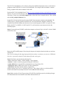
To understand how the UART's receiver extracts encoded data, assume it has a clock running at a multiple
of the baud rate (e.g., 16x). Starting in the idle state (as shown in Fig.3), the receiver “samples” its RX
signal until it detects a high-low transition. Then, it waits 1.5 bit periods (24 clock periods) to sample its RX
signal at what it estimates to be the center of data bit 0. The receiver then samples RX at bit-period intervals
(16 clock periods) until it has read the remaining 7 data bits and the stop bit. From that point this process is
repeated. Successful extraction of the data from a frame requires that, over 10.5 bit periods, the drift of the
receiver clock relative to the transmitter clock be less than 0.5 periods in order to correctly detect the stop
bit.
Figure 3 Illustration of signal decoding.
UARTs can be used to interface to a wide variety of other peripherals. For example, widely available
GSM/GPRS cell phone modems and Bluetooth modems can be interfaced to a microcontroller UART.
Similarly GPS receivers frequently support UART interfaces.
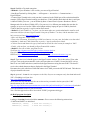
The NXP LPC1768 microcontroller includes four such devices/peripherals called UARTs: UART0/2/3 and
UART1. See pages 298 and 318 of the LPC17xx User’s Manual [1]. See also page 27 of the Datasheet [2].
UART0 and UART1 of the microcontroller are connected on the MCB1700 board to the ST3232C (IC6),
which converts the logic signals to RS-232 voltage levels. This connection is realized from pins
{P0.2/TXD0/AD0.7 and P0.3/RXD0/AD0.6} and { P2.0/PWM1.1/TXD1 and P2.1/PWM1.2/RXD1} of the
microcontroller to the pins {10, 9, 11, and 12} ST3232C chip. The ST3232C chip drives the two COM0
and COM1 represented by the two female DB9 connectors (Note: if you use an Embest LPC1700 board,
then, note that these two connectors are male DB9 connectors). To see these connections, take a look on
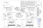
pages 1 and 3 of the schematic diagram of the board [3] (included also in the downloadable files of this
lab#2).
For more details on UART and RS-232, please read references [1-6].
In this lab we will explore serial communication between the (target) LPC1768 UART and a serial
communication port of the host PC.
3. EXAMPLE 1: Microcontroller “echoes” back the characters sent by host computer
(a) Experiment
In the first example of this lab, we’ll use an example project that comes with the “LPC1700 code bundle”.
2