1
Lab 2: Using UART
EE-379 Embedded Systems and Applications
Electrical Engineering Department, University at Buffalo
Last update: Cristinel Ababei, January 2013
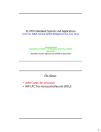
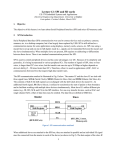
1. Objective
The objective of this lab is to utilize the Universal Asynchronous Receiver/Transmitter (UART) to connect
the MCB1700 board to the host computer. Also, we introduce the concept of interrupts briefly. In the
example project, we send characters to the microcontroller unit (MCU) of the board by pressing keys on the
keyboard. These characters are sent back (i.e., echoed, looped-back) to the host computer by the MCU and
are displayed in a hyperterminal window.
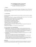
2. UART
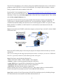
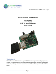
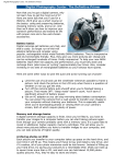
The most basic method for communication with an embedded processor is asynchronous serial. It is
implemented over a symmetric pair of wires connecting two devices (referred as host and target here,
though these terms are arbitrary). Whenever the host has data to send to the target, it does so by sending an
encoded bit stream over its transmit (TX) wire. This data is received by the target over its receive (RX)
wire. The communication is similar in the opposite direction. This simple arrangement is illustrated in
Fig.1. This mode of communications is called “asynchronous” because the host and target share no time
reference (no clock signal). Instead, temporal properties are encoded in the bit stream by the transmitter and
must be decoded by the receiver.
Figure 1 Basic serial communication.
A commonly used device for encoding and decoding such asynchronous bit streams is a Universal
Asynchronous Receiver/Transmitter (UART). UART is a circuit that sends parallel data through a serial
line. UARTs are frequently used in conjunction with the RS-232 standard (or specification), which specifies
the electrical, mechanical, functional, and procedural characteristics of two data communication equipment.
A UART includes a transmitter and a receiver. The transmitter is essentially a special shift register that
loads data in parallel and then shifts it out bit by bit at a specific rate. The receiver, on the other hand, shifts
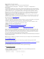
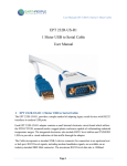
in data bit by bit and reassembles the data. The serial line is ‘1’ when it is idle. The transmission starts with
a start-bit, which is ‘0’, followed by data-bits and an optional parity-bit, and ends with stop-bits, which are
‘1’. The number of data-bits can be 6, 7, or 8. The optional parity bit is used for error detection. For odd
parity, it is set to ‘0’ when the data bits have an odd number of ‘1’s. For even parity, it is set to ‘0’ when the
data-bits have an even number of ‘1’s. The number of stop-bits can be 1, 1.5, or 2. The transmission with 8
data-bits, no parity, and 1 stop-bit is shown in Fig.2 (note that the LSB of the data word is transmitted first).
Figure 2 Transmission of a byte.
1
No clock information is conveyed through the serial line. Before the transmission starts, the transmitter and
receiver must agree on a set of parameters in advance, which include the baud-rate (i.e., number of bits per
second), the number of data bits and stop bits, and use of parity bit.
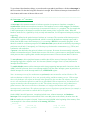
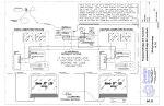
To understand how the UART's receiver extracts encoded data, assume it has a clock running at a multiple
of the baud rate (e.g., 16x). Starting in the idle state (as shown in Fig.3), the receiver “samples” its RX
signal until it detects a high-low transition. Then, it waits 1.5 bit periods (24 clock periods) to sample its RX
signal at what it estimates to be the center of data bit 0. The receiver then samples RX at bit-period intervals
(16 clock periods) until it has read the remaining 7 data bits and the stop bit. From that point this process is
repeated. Successful extraction of the data from a frame requires that, over 10.5 bit periods, the drift of the
receiver clock relative to the transmitter clock be less than 0.5 periods in order to correctly detect the stop
bit.
Figure 3 Illustration of signal decoding.
UARTs can be used to interface to a wide variety of other peripherals. For example, widely available
GSM/GPRS cell phone modems and Bluetooth modems can be interfaced to a microcontroller UART.
Similarly GPS receivers frequently support UART interfaces.
The NXP LPC1768 microcontroller includes four such devices/peripherals called UARTs: UART0/2/3 and
UART1. See pages 298 and 318 of the LPC17xx User’s Manual [1]. See also page 27 of the Datasheet [2].
UART0 and UART1 of the microcontroller are connected on the MCB1700 board to the ST3232C (IC6),
which converts the logic signals to RS-232 voltage levels. This connection is realized from pins
{P0.2/TXD0/AD0.7 and P0.3/RXD0/AD0.6} and { P2.0/PWM1.1/TXD1 and P2.1/PWM1.2/RXD1} of the
microcontroller to the pins {10, 9, 11, and 12} ST3232C chip. The ST3232C chip drives the two COM0
and COM1 represented by the two female DB9 connectors (Note: if you use an Embest LPC1700 board,
then, note that these two connectors are male DB9 connectors). To see these connections, take a look on
pages 1 and 3 of the schematic diagram of the board [3] (included also in the downloadable files of this
lab#2).
For more details on UART and RS-232, please read references [1-6].
In this lab we will explore serial communication between the (target) LPC1768 UART and a serial
communication port of the host PC.
3. EXAMPLE 1: Microcontroller “echoes” back the characters sent by host computer
(a) Experiment
In the first example of this lab, we’ll use an example project that comes with the “LPC1700 code bundle”.
2
The LPC1700 Code Bundle is a free software package from NXP that demonstrates the use of the built-in
peripherals on the NXP LPC17xx series of microcontrollers. The example software includes a common
library, peripheral APIs, and test modules for the APIs.
Download LPC1700 Code Bundle from [7] (http://ics.nxp.com/support/software/code.bundle.lpc17xx.keil/)
and save it in your own work directory. Save it with the plan to keep it as we’ll revisit some other example
in the future. Unzip it to get the keil_examples folder created with several examples therein. Take a minute
and read keil_example/readme.txt now.
Launch Keil uVision4 and then open the project UART from among the example just downloaded. The
UART project is a simple program for the NXP LPC17xx microcontrollers using Keil’s MCB1700
evaluation board. When sending some characters from a terminal program on the PC at a speed of 57600
Baud to the LPC17xx UART0 or UART1 the LPC17xx will echo those same characters back to the
terminal program.
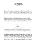
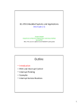
Step 1: Connect the board, ULINK2, and the host computer as shown in Fig.4. Ask the TA for the COM0/1
to Serial Port cable.
Figure 4 Hardware setup.
Remove the RST and ISP jumpers. Please keep the jumpers safe and place them back when you are done
with this lab.
Note: If you are doing this lab using a laptop which does not have a serial port, you can use a USB Serial
Converter. I got mine for about $12 from Amazon [8] and it works great.
Step 2: Familiarize yourself with the following files:
--uart.c: contains the UART0 / UART1 handlers / driver functions
--uarttest.c: contains a small test program utilizing the UART driver
--system_LPC17xx.c: Cortex-M3 Device Peripheral Access Layer Source File
--startup_LPC17xx.s: CMSIS Cortex-M3 Core Device Startup File
--Abstract.txt: Describes what the uarttest.c program does
Change "#include "lpc17xx.h" to "#include <lpc17xx.h>. This is done in order to use the latest Keil’s
release of the header file (normally located in C:\Keil\ARM\INC\NXP directory).
Step 3: Make sure the uVision4 Target setting is FLASH. Then, build the project by rebuilding all target
files. Download to the microcontroller and confirm that download is ok.
3
Step 4: Establish a Terminal connection
--Method 1: If your Windows is XP or older, you can use HyperTerminal:
--Start HyperTerminal by clicking Start - > All Programs -> Accessories -> Communications ->
HyperTerminal
--Connect HyperTerminal to the serial port that is connected to the COM0 port of the evaluation board for
example. For the HyperTerminal settings you should use: COM1 (double check that it the host’s serial port
is indeed COM1in your case – you can do that by Start->Control Panel->System->Hardware->Device
Manager and click on Ports (COM & LPT); if in your case it’s a different port number then use that; for
example, in my case as I use the USB to serial adapter with my laptop, the port is COM14), baud rate
57600, 8 data bits, no parity, 1 stop bit, and no flow control.
--Method 2: If your Windows is 7 or newer, you first must make sure you download and/or install a serial
connection interface (because HyperTerminal is not part of Windows 7 or later). On the machines in the
lab, you can use Putty (http://www.putty.org):
--Start->All Programs->Putty->Putty
--Then, select Connection, Serial and type COM1 (or whatever is in your case; find what it is as described
in Method 1), baud rate 57600, 8 data bits, no parity, 1 stop bit, and no flow control.
--Click on Session and choose the type of connection as Serial. Save the session for example as "lab2".
--Finally, click on Open; you should get HyperTerminal like window.
--Method 3: You can use other programs such as:
TeraTerm (http://logmett.com/index.php?/products/teraterm.html) or
HyperSerialPort (http://www.hyperserialport.com/index.html) or
RealTerm (http://realterm.sourceforge.net) or CoolTerm (http://freeware.the-meiers.org), etc.
Step 5: Type some text. It should appear in the HyperTerminal window. This is the result of: First, what
you type is sent to the microcontroller via the serial port (that uses a UART). Second, the MCU receives
that via its own UART and echoes (sends back) the typed characters using the same UART. The host PC
receives the echoed characters that are displayed in the HyperTerminal.
Disconnect the serial cable from COM0 and connect it to COM1 port on the MCB1700 board. The behavior
of project should be the same.
Step 6: (optional – do not do it on computers in the lab): On your own computer only, download and install
NXP’s FlashMagic tool from here:
http://www.flashmagictool.com/
Then, follow the steps that describe how to use this tool as presented in the last part of the UART
documentation for the code bundle:
http://ics.nxp.com/literature/presentations/microcontrollers/pdf/code.bundle.lpc17xx.keil.uart.pdf (included
in the downloadable archive of files for this lab).
Note: With this approach one does not need the ULINK2 programmer/debugger.
(b) Brief program description
Looking at the main() function inside the uarttest.c file we can see the following main actions:
--UART0 and UART1 are initialized:
UARTInit(0, 57600);
UARTInit(1, 57600);
/* baud rate setting */
/* baud rate setting */
4
--A while loop which executes indefinitely either for UART0 or for UART1. The instructions executed
inside this loop (let’s assume the UART0) are:
Disable Receiver Buffer Register (RBR), which contains the next received character to be read. This is
achieved by setting all bits of the Interrupt Enable Register (IER) to ‘0’ except bits THRE and RLS. In
this way the LSB (i.e., bit index 0 out of 32 bits) of IER register is set to ‘0’. The role of this bit (as
explained in the LPC17xx User’s Manual [1] on page 302) when set to ‘0’ is to disable the Receive
Data Available interrupt for UART0.
Send back to the host the characters from the buffer UART0Buffer. This is done only if there are
characters in the buffer (the total buffer size is 40 characters) which have been received so far from the
host PC. The number of characters received so far and not yet echoed back is stored and updated in
UART0Count.
Once the transmission of all characters from the buffer is done, reset the counter UART0Count.
Enable Receiver Buffer Register (RBR). This is achieved by setting to ‘1’ the LSB of IER, which in
turn is achieved using the mask IER_RBR.
(c) Source code discussion
Please take your time now to thoroughly browse the source code in files uart.c and uarttest.c files. Open
and read other files as necessary to track the declarations and descriptions of variables and functions.
For example, in uarttest.c we see:
--A function call SystemClockUpdate();
This is described in source file system_LPC17xx.c which we locate in the Project panel of the uVision4
IDE. Click on the name of this file to open and search inside it the description of SystemClockUpdate().
This function is declared in header file system_LPC17xx.h. Open these files and try to understand how this
function is implemented; what each of the source code lines do?
--A function call UARTInit(0, 57600);
This function is described in source file uart.c. The declaration of this function is done inside header file
uart.h. Open these files and read the whole code; try to understand each line of the code.
--An instruction:
LPC_UART0->IER = IER_THRE | IER_RLS;
/* Disable RBR */
Based on what’s been studied in lab#1 you should know already that LPC_UART0 is an address of a
memory location – the UART0 peripheral is “mapped” to this memory location. Starting with this memory
location, several consecutive memory locations represent “registers” associated with this peripheral/device
called UART0. All 14 such registers (or memory locations) are listed on page 300 of the User Manual.
Utilizing this peripheral is done through reading/writing into these registers according to their meaning and
rules described in the manual. For example, one of the 14 registers associated with UART0 is Interrupt
Enable Register (IER).
Form a C programming perspective, LPC_UART0 is declared inside header file LPC17xx.h:
#define LPC_UART0
((LPC_UART_TypeDef
*) LPC_UART0_BASE
)
Which also declares what LPC_UART0_BASE as:
#define LPC_UART0_BASE
(LPC_APB0_BASE + 0x0C000)
Where LPC_APB0_BASE is declared at its turn in the same file:
#define LPC_APB0_BASE
(0x40000000UL)
This effectively makes LPC_UART0_BASE to have value: 0x4000C000, which not surprisingly coincides
with what is reported on page 14 of the LPC17xx User’s Manual!
5
Furthermore, the Interrupt Enable Register (IER) contains individual interrupt enable bits for the 7 potential
UART interrupts. The IER register for UART0 is “mapped” (or associated with) to memory address
0x4000C004 as seen on page 300 of the LPC17xx User’s Manual. This fact is captured in the struct
declaration of LPC_UART_TypeDef inside the header file LPC17xx.h (open this file and double check
it!). As a result, in our C programming, we can refer to the IER register as in the instruction that we are
currently discussing: LPC_UART0->IER, which basically stores/represents the address 0x4000C004.
In addition, note that IER_THRE and IER_RLS are declared inside the header file uart.h as:
#define IER_THRE
#define IER_RLS
0x02
0x04
Which are utilized as masks in our instruction:
LPC_UART0->IER = IER_THRE | IER_RLS;
/* Disable RBR */
So, finally as we see, the effect of this instruction is simply to turn ‘1’ bit index 1 (the second LSB out of 32
bits) and bit index 2 (the third LSB out of 32 bits) of the IER register! All other bits are set to ‘0’.
Having bit index 1 of this register set to ‘1’ enables the Transmit Holding Register Empty (THRE) flag for
UART0 – see page 302, Table 275 of the LPC17xx User’s Manual. Having bit index 2 of this register set to
‘1’ enables the UART0 RX line status interrupts – see page 302, Table 275 of the LPC17xx User’s Manual.
As already said, all other bits are set therefore via this masking to ‘0’. This includes the LSB (i.e., bit index
0 out of 32 bits) of IER register, which is set to ‘0’. The role of this bit (as explained in the LPC17xx User’s
Manual on page 302) when set to ‘0’ is to disable the Receive Data Available interrupt for UART0.
You should be able now to explain what the following instruction does:
LPC_UART0->IER = IER_THRE | IER_RLS | IER_RBR;
/* Re-enable RBR */
Summarizing, what the code inside uarttest.c does is (as also mentioned in the previous section):
--disable receiving data
--send back data to the PC from the buffer (i.e., array variable UART0Buffer)
--reset counter of characters stored in buffer
--enable receiving data
Note: As mentioned in lab#1, in general one would not need to worry about these details about addresses to
which registers are mapped. It would be sufficient to just know of for example the definition and declaration
of LPC_UART_TypeDef inside the header file LPC17xx.h. To the C programmer, it is transparent to what
exact address the register IER is mapped to for example. However, now at the beginning, it’s instructive to
track these things so that we get a better global picture of these concepts. It also forces us to get better used
with the LPC17xx User’s Manual and the datasheets.
Notice that inside the source file uart.c we have these two function descriptions:
void UART0_IRQHandler (void) {...}
void UART1_IRQHandler (void) {...}
which are not called for example inside uarttest.c, but they appear inside startup_LPC17xx.s:
DCD
UART0_IRQHandler
; 21: UART0
DCD
UART1_IRQHandler
; 22: UART1
The function void UART0_IRQHandler (void) is the UART0 interrupt handler. Its name is
UART0_IRQHandler because it is named like that by the startup code inside the file startup_LPC17xx.s.
DCD is an assembler directive (or pseudo-op) that defines a 32-bit constant.
6
To get a better idea about these things, we need to make a parenthesis and discuss a bit about interrupts in
the next section. For the time being this discussion is enough. We will discuss interrupts in more details in
class lectures and in some of the next labs as well.
---------------------------------------------------------------------------------------------------------------------------------(d) Interrupts – a 1st encounter
An interrupt is the automatic transfer of software execution in response to a hardware event that is
asynchronous with the current software execution. This hardware event is called a trigger. The hardware
event can either be a busy to ready transition in an external I/O device (i.e., peripheral, like for example the
UART input/output) or an internal event (like bus fault, memory fault, or a periodic timer). When the
hardware needs service, signified by a busy to ready state transition, it will request an interrupt by setting its
trigger flag.
A thread is defined as the path of action of software as it executes. The execution of the interrupt service
routine (ISR) is called as a background thread, which is created by the hardware interrupt request and is
killed when the ISR returns from interrupt (e.g., by executing a BX LR in an assembly program). A new
thread is created for each interrupt request. In a multi-threaded system, threads are normally cooperating to
perform an overall task. Consequently, we’ll develop ways for threads to communicate (e.g., FIFOs) and
synchronize with each other.
A process is also defined as the action of software as it executes. Processes do not necessarily cooperate
towards a common shared goal. Threads share access to I/O devices, system resources, and global variables,
while processes have separate global variables and system resources. Processes do not share I/O devices.
To arm (disarm) a device/peripheral means to enable (shut off) the source of interrupts. Each potential
interrupting trigger has a separate “arm” bit. One arms (disarms) a trigger if one is (is not) interested in
interrupts from this source.
To enable (disable) means to allow interrupts at this time (postponing interrupts until a later time). On the
ARM Coretx-M3 processor, there is one interrupt enable bit for the entire interrupt system. In particular, to
disable interrupts we set the interrupt mask bit, I, in PRIMASK register.
Note: An interrupt is one of five mechanisms to synchronize a microcontroller with an I/O device. The
other mechanisms are blind cycle, busy wait, periodic polling, and direct memory access. With an input
device, the hardware will request an interrupt when input device has new data. The software interrupt
service will read from the input device and save in global RAM. With an output device, the hardware will
request an interrupt when the output device is idle. The software interrupt service will get data from a
global structure, and write it to the device. Sometimes, we configure the hardware timer to request
interrupts on a periodic basis. The software interrupt service will perform a special function; for example, a
data acquisition system needs to read the ADC at a regular rate.
On the ARM Cortex-M3 processor, exceptions include resets, software interrupts, and hardware
interrupts. Each exception has an associated 32-bit vector that points to the memory location where the
ISR that handles the exception is located. Vectors are stored in ROM at the beginning of the memory. Here
is an example of a few vectors as defined inside startup_LPC17xx.s:
__Vectors
DCD
DCD
__initial_sp
Reset_Handler
; Top of Stack
; Reset Handler
7
DCD
NMI_Handler
DCD
HardFault_Handler
...
; External Interrupts
DCD
WDT_IRQHandler
DCD
TIMER0_IRQHandler
...
DCD
UART0_IRQHandler
...
; NMI Handler
; Hard Fault Handler
; 16: Watchdog Timer
; 17: Timer0
; 21: UART0
ROM location 0x00000000 has the initial stack pointer and location 0x00000004 contains the initial
program counter (PC), which is called the reset vector. It points to a function called reset handler, which is
the first thing executed following reset.
Interrupts on the Cortex-M3 are controlled by the Nested Vector Interrupt Controller (NVIC). To activate
an “interrupt source” we need to set its priority and enable that source in the NVIC (i.e., activate =
set priority + enable source in NVIC). This activation is in addition to the “arm” and “enable” steps
discussed earlier.
Table 50 in the User Manual (page 73) lists the interrupt sources for each peripheral function. Table 51
(page 76 in User Manual) summarizes the registers in the NVIC as implemented in the LPC17xx
microcontroller. Read the entire Chapter 6 of the User Manual (pages 72-90) and identify the priority and
enable registers and their fields of the NVIC. Pay particular attention to (i.e., search/watch for) UART0 in
this Chapter. How would you set the priority and enable UART0 as a source of interrupts?
---------------------------------------------------------------------------------------------------------------------------------Coming back to our discussion of the function void UART0_IRQHandler (void) in uart.c, we see a first
instruction:
IIRValue = LPC_UART0->IIR;
What does it do? It simply reads the value of LPC_UART0->IIR and assigns it to a variable whose name
is IIRValue. LPC_UART0->IIR is the value of the register IIR (Interrupt IDentification Register identifies which interrupt(s) are pending), which is one of several (14 of them) registers associated with the
UART0 peripheral/device. You can see it as well as the other registers on page 300 of the User Manual.
Take a while and read them all. The fields of the interrupt register IIR are later described on page 303 in the
User Manual. Take another while and read them all on pages 303-304.
Next inside uart.c we see:
IIRValue >>= 1;
IIRValue &= 0x07;
/* skip pending bit in IIR */
/* check bit 1~3, interrupt identification */
Which shifts right with one bit IIRValue and then AND’s it with 0x07. This effectively “zooms-in” onto the
field formed by bits index 1-3 from the original LPC_UART0->IIR, bits which are now in the position bits
index 0-2 of IIRValue variable.
Going on, we find an “if” instruction with several branches:
if ( IIRValue == IIR_RLS )
{...
}
else if ( IIRValue == IIR_RDA )
{...
}
else if ( IIRValue == IIR_CTI )
/* Receive Line Status */
/* Receive Data Available */
/* Character timeout indicator */
8
{...
}
else if ( IIRValue == IIR_THRE )
{...
}
/* THRE, transmit holding register empty */
See in Table 276 on page 303 in the User Manual what is the meaning of the three bits 1-3 from the original
IIR register:
011
010
110
001
1 - Receive Line Status (RLS).
2a - Receive Data Available (RDA).
2b - Character Time-out Indicator (CTI).
3 - THRE Interrupt
For each of these situations, something else is done inside the corresponding branch of the “if” instruction
above. In other words, we first identify the interrupt, and for each ID we do something else. If none of the
expected IDs is found, we do nothing. Please take your time now to explain what’s done in each of these
cases. Read pages 303-304 in the User Manual for this. This is very important in order to understand the
overall operation of the example of this lab.
4. Lab Assignment
1) (not graded and should not be discussed in the lab report) Use a Debug session to step through the
execution of this program. The scope is for you to better understand its operation. See lab#1 for how to
use/run a debug session. See also documentation of the code bundle from NXP [7].
2) Answer the question: Why did we need to remove the ISP and RST jumpers in Example 1?
3) Describe in less than a page (typed, font size 11, single line spacing) all instructions inside the function
void UART0_IRQHandler (void) for each of the branches of the main “if” instruction. Include this in your
lab report.
4) Modify Example 1 such that the characters typed on the host’s keyboard are also displayed on the LCD
display on the board. (Hint: re-use code from Blinky2 example of lab#1)
5. Credits and references
[1] LPC17xx user’s manual; http://www.nxp.com/documents/user_manual/UM10360.pdf (part of lab#1
files)
[2] NXP LPC17xx Datasheet;
http://www.nxp.com/documents/data_sheet/LPC1769_68_67_66_65_64_63.pdf (part of lab#1 files)
[3] Schematic Diagram of the MCB1700 board; http://www.keil.com/mcb1700/mcb1700-schematics.pdf
(part of lab#2 files)
[4] MCB1700 Serial Ports; http://www.keil.com/support/man/docs/mcb1700/mcb1700_to_serial.htm
[5] UART entry on Wikipedia (click also on the references therein for RS-232);
http://en.wikipedia.org/wiki/Universal_asynchronous_receiver/transmitter
[6]
--Jonathan W. Valvano, Embedded Systems: Introduction to Arm Cortex-M3 Microcontrollers, 2012.
(Chapters 8,9)
--Pong P. Chu, FPGA Prototyping by VHDL Examples: Xilinx Spartan-3 Version, Wiley 2008. (Chapter 7)
--Lab manual of course http://homes.soic.indiana.edu/geobrown/c335 (Chapter 5)
--EE 472 Course Note Pack, Univ. of Washington, 2009,
http://abstract.cs.washington.edu/~shwetak/classes/ee472/notes/472_note_pack.pdf (Chapter 8)
9
[7] LPC1700 Code Bundle;
Download: http://ics.nxp.com/support/software/code.bundle.lpc17xx.keil/
Documentation:
http://ics.nxp.com/literature/presentations/microcontrollers/pdf/code.bundle.lpc17xx.keil.uart.pdf
[8] Plugable USB to RS-232 DB9 Serial Adapter;
Amazon: http://www.amazon.com/Plugable-Adapter-Prolific-PL2303HXChipset/dp/B00425S1H8/ref=sr_1_1?ie=UTF8&qid=1359988639&sr=81&keywords=plugable+usb+to+serial
Tigerdirect: http://www.tigerdirect.com/applications/SearchTools/itemdetails.asp?EdpNo=3753055&CatId=464
10