1
MITSUBISHI ELECTRIC
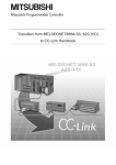
MELSEC A/Q Series
Programmable Logic Controllers
User's Manual
CC-Link System
Compact Type
Remote I/O Modules
Art. no.: 103494
01 07 2004
SH(NA)-4007
Version O
MITSUBISHI ELECTRIC
INDUSTRIAL AUTOMATION
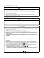
• SAFETY PRECAUTIONS •
(Always read these instructions before using this equipment.)
Before using this product, please read this manual and the relevant manuals introduced in this manual
carefully and pay full attention to safety to handle the product correctly.
The instructions given in this manual are concerned with this product. For the safety instructions of the
programmable controller system, please read the CPU module user's manual.
In this manual, the safety instructions are ranked as "DANGER" and "CAUTION".
DANGER
Indicates that incorrect handling may cause hazardous conditions,
resulting in death or severe injury.
! CAUTION
Indicates that incorrect handling may cause hazardous conditions,
resulting in medium or slight personal injury or physical damage.
!
Note that the ! CAUTION level may lead to a serious consequence according to the circumstances.
Always follow the instructions of both levels because they are important to personal safety.
Please save this manual to make it accessible when required and always forward it to the end user.
[Design Precautions]
!
DANGER
• When there are communication errors with the data link, the communication error station will
enter the following condition.
Build an interlock circuit into the sequence program to operate system safely by using the
communication state information.
An accident may occur by a false output or a malfunction.
(1) Turn off all input from Remote I/O station.
(2) Turn off all output from Remote I/O station.
• The output may be left ON or OFF due to trouble in the remote I/O module.
Configure a circuit to monitor output signals which may lead to a serious accident..
!
CAUTION
• Use the module in an environment that meets the general specifications contained in this manual.
Using this module in an environment outside the range of the general specifications could result
in electric shock, fire, malfunction, and damage to or deterioration of the product.
• Do not bunch the control wires or communication cables with the main circuit or power wires, or
install them close to each other. (AJ65SBTW -16 only)
They should be installed 100 mm (3.9 in.) or more from each other.
Not doing so could result in noise that would cause malfunction.
A-1
A-1
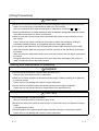
[Installation Precautions]
!
CAUTION
• Do not directly touch the module's conductive parts.
Doing so could cause malfunction or failure in the module.
• Make sure to fix the module with DIN rail or installation screws and tighten the installation
screws with the specified torque.
• Make sure to connect the connector of each connecting cable to the attachment part.
Defective contact could cause malfunction.
[Wiring Precautions]
!
DANGER
• Before beginning any installation or wiring work, make sure that all phases of the power supply
have been obstructed from the outside.
Failure to completely shut off the power supply phases may cause electric shock and/or damage
to the module.
!
CAUTION
• The FG terminals should always be grounding using the class-D (class-3) or higher grounding
designed specially for the PLC.
• Make sure to use the spare terminal screws as it is tightened.
Failure to do so could make a short circuit with bare solderless terminals.
• When wiring the module, check the rated voltage and terminal layout and make sure the wiring
is done correctly.
Connecting a power supply that differs from the rated voltage or wiring it incorrectly may cause
fire or failure.
• Tighten the terminal screws within the range of specified torque.
If the terminal screws are loose, it may result in fire or malfunction.
Tightening the screws too far may cause damage to the screws, resulting in short circuit or
malfunction.
• When securing the CC-Link cable or power cable using the through pipe of the waterproof
remote I/O module, securely tighten the nuts using a wrench or the like. Loose nuts may result
in malfunction due to water intrusion. (AJ65SBTW -16 only.)
• Carry out tightening of the waterproof cap and communications adapter installation screws
within the specified tightening torque range. (AJ65FBTA -16 only.)
If the screws are loose, it could cause fire or malfunction.
If the screws are overtightened, they could be damaged, and this could cause a short circuit or
malfunction.
• The IP67 is satisfactory only when all the waterproof plugs, waterproof caps and
communications adapters are installed (AJ65FBTA -16 only.)
A-2
A-2
[Wiring Precautions]
!
CAUTION
• Since the I/O connector, communications connector and power supply connector are the same
shape, do not connect the communications cable to the I/O connector.
Doing so could cause the module to break down or malfunction. (AJ65FBTA -16 only.)
• Make sure that there are no foreign substances such as sawdust or wiring debris inside the module.
Such debris could cause fire, failure or malfunction.
• Make sure that the communication cable connected to the module is kept in the duct or fixed
with cramps.
Failure to do so may cause a damage to the module or cables due to dangling, shifting or
inadvertent handling of cables, or misoperation because of bad cable contacts.
• Do not grab on the cable when removing the communication cable connected to the module.
When removing the cable with a connector, hold the connector on the side that is connected to
the module.
When removing the cable without a connector, loose the screws on the side that is connected to
the module.
Pulling the cable that is still connected to the module may cause a damage to the module or
cable, or malfunction due to bad cable contacts.
[Starting and Maintenance Precautions]
!
DANGER
• Do not touch the terminals or connector while the power is on.
Doing so may cause electric shock or malfunction.
• Make sure to switch all phases of the external power supply off before cleaning or re-tightening
the terminal screws.
Failure to do so may damage the module or cause malfunction.
• Set the sink/source selector switch after shutting off the power supply at all phases.
Failure to do so may result in failures or malfunctions in the opponent device.
!
CAUTION
• Do not disassemble or modify the module.
Doing so could cause failure, malfunction, injury or fire.
• Because the case of the module is made of resin, be careful not to drop it or expose it to strong
impact.
It may damage the module.
• Switch all phases of the external power supply off before mounting or removing the module.
Failure to do so may damage the module or cause malfunction.
A-3
A-3
[Disposal Precautions]
!
CAUTION
• When disposing of this product, treat it as industrial waste.
A-4
A-4
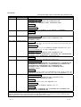
REVISIONS
* The manual number is given on the bottom left of the back cover.
Print Date
June 1998
Nov. 1998
Apr. 1999
* Manual Number
Revision
SH(NA)-4007-A First printing
SH(NA)-4007-B
Additional model
AJ65SBTB1-8D, AJ65SBTC4-16D, AJ65SBTW4-16D
AJ65SBTB1-8T, AJ65SBTC4-16DT, AJ65SBTW4-16DT
Addition
Section 7.3, 7.4
Correction
Section 1.1, 1.2, 1.4, Chapter 2, 4, 5, 6, Section 7.1, Appendix 1
SH(NA)-4007-C
Addition
Contents
Section 8.2.2
June 1999
SH(NA)-4007-D
Additional model
AJ65SBTB1-32T1, AJ65SBTCF1-32D, AJ65SBTCF1-32T,
AJ65SBTCF1-32DT
Nov. 1999
SH(NA)-4007-E
Addition
Section 1.4, 4.1.6, 4.1.7, 4.4, 5.1.8, 5.1.9, 5.1.10, 5.1.11, 5.3, 6.1, 6.4, 7.4,
Appendix 1.6, 1.7, 1.8
Correction
Section 1.1, 1.2, 1.3, 1.5, 1.6, Chapter 2, Chapter 3, Section 4.2.1, 4.3.1,
6.2.1, 6.3.1, Section 7.1, 7.4, 8.2.1, Appendix 1
Additional model
AJ65SBTB1-32DT, AJ65SBTCF1-32D, AJ65SBTCF1-32T,
AJ65SBTCF1-32DT, AJ65SBTB2-8A, AJ65SBTB2-16A, AJ65SBTB2-8R,
AJ65SBTB2-16R, AJ65SBTB2-8S, AJ65SBTB2-16S
Dec. 1999
SH(NA)-4007-F
Addition
Section 1.2, 4.1.6, 4.1.7, 5.1.8, 5.1.9, 5.1.10, 5.1.11
Mar. 2000
SH(NA)-4007-G
Additional model
AJ65SBTB2N-8A, AJ65SBTB2N-16A, AJ65SBTB3-8D, AJ65SBTB3-16D,
AJ65SBTB2-8T, AJ65SBTB2-16T, AJ65SBTB2N-8R, AJ65SBTB-16R,
AJ65SBTB2N-8S, AJ65SBTB2N-16S, AJ65SBTB32-8DT,
AJ65SBTB32-16DT, AJ65SBTB1-16DT, AJ65SBTB1-16DT1,
AJ65SBTB1-32DT1
Addition
Section 4.1.8, 4.1.9, 4.1.10, 4.1.11, Section 5.1.12, 5.1.13, 5.1.14, 5.1.15,
5.1.16, 5.1.17, Section 6.1.1, 6.1.3, 6.1.4, 6.1.5, 6.1.6, Appendix 1.9, 1.10
Oct. 2000
SH(NA)-4007-H
Additional model
AJ65VBTCU3-8D1, AJ65VBTCU3-16D1, AJ65VBTCU2-8T,
AJ65VBTCU2-16T, AJ65VBTCF1-32DT1
Addition
Section 4.5, 5.4, 6.5, 7.2.3, 7.2.4, Appendix 1.13
Correction
Section 1.1, 1.4, 1.5, Chapter 2, Section 4.3.1, 7.1
Deletion
AJ65SBTB2-8A, AJ65SBTB2-16A, AJ65SBTB2-8R, AJ65SBTB2-16R,
AJ65SBTB2-8S, AJ65SBTB2-16S
This manual confers no industrial property rights or any rights of any other kind, nor does it confer any patent
licenses. Mitsubishi Electric Corporation cannot be held responsible for any problems involving industrial property
rights which may occur as a result of using the contents noted in this manual.
1998 MITSUBISHI ELECTRIC CORPORATION
A-5
A-5
Print Date
Jan. 2001
* Manual Number
SH(NA)-4007-I
Jul. 2001
SH(NA)-4007-J
Additional model
AJ65FBTA2-16T, AJ65FBTA2-16TE
Correction
Section 1.2, 1.4, 1.5, 4.1.6, 4.1.7, 4.2.1, 4.2.2, 4.3.1, 6.2.1, 6.2.2, 6.3.1,
6.5.1, 6.6.1, 6.6.2, 7.2.3
Appendix 1.14
Sep. 2001
SH(NA)-4007-K
Additional model
AJ65SBTB1-16DT2, AJ65SBTB1-32DT2
Correction
Section 1.4, 6.1.1, 8.2.1, Appendix 1.13
Jan. 2002
SH(NA)-4007-L
Additional model
AJ65SBTB1-8T1, AJ65SBTB2-8T1, AJ65SBTB2-16T1, AJ65SBTC1-32T1,
AJ65SBTB1-16DT3, AJ65SBTB1-32DT3, AJ65SBTB32-8DT2,
AJ65SBTB32-16DT2, AJ65SBTC4-16DT2, AJ65SBTC1-32DT2,
AJ65SBTC1-32DT3
Correction
Section 1.3, 1.4, 1.5, 5.5.2, 6.1.1, 7.7, 8.2.1
Appendix 1.13
Changed item numbers
Section 5.1.4 to Section 5.1.9 Section 5.1.5 to Section 5.1.10
Section 5.1.10 to Section 5.1.13 Section 5.1.13 to Section 5.1.16
Section 6.1.5 to Section 6.1.6 Section 6.1.9 to Section 6.1.10
Section 6.2.2 to Section 6.2.3 Section 6.2.3 to Section 6.2.4
Dec. 2002
SH(NA)-4007-M
Correction
Section 2, Section 4 to Section 6, Section 8.2.1
May. 2003
SH(NA)-4007-N
Correction
Section 1.3, 1.6
Jun. 2004
SH(NA)-4007-O
Additional model
AJ65VBTS3-16D, AJ65VBTS3-32D, AJ65VBTS2-16T, AJ65VBTS2-32T,
AJ65VBTS32-16DT, AJ65VBTS32-32DT, AJ65VBTCE3-8D,
AJ65VBTCE3-16D, AJ65VBTCE2-8T, AJ65VBTCE2-16T, AJ65VBTCE3216DT
Addition
Section 1.6.1 to 1.6.3, 4.5.3 to 4.5.5, 5.4.3 to 5.4.5, 6.5.2 to 6.5.4, 7.8, 7.9
Appendix 1.15, 1.16
Correction
Chapter 1, 2, Section 4.4.1, 4.5, 5.1, 5.4, 6.1, 6.5, 6.2.2, 6.4.1, 6.5.1, 7.2 to
7.4
A-6
Revision
Additional model
AJ65FBTA4-16D, AJ65FBTA4-16DE,
AJ65FBTA42-16DT, AJ65FBTA42-16DTE
Addition
Section 1.6, 7.4, Appendix 1.14
Correction
Section 1.2, 1.4, 1.5, Chapter 2,3,
Section 4.5.2, 5.3.1, 5.4.1, 5.4.2, 6.5.1, 7.1
Appendix 1.13
A-6
INTRODUCTION
Thank you for purchasing the MELSEC-A series PLC.
Before using the equipment, please read this manual carefully to develop full familiarity with the functions
and performance of the A-series PLC you have purchased, so as to ensure correct use.
Please forward a copy of this manual to the end user.
CONTENTS
SAFETY PRECAUTIONS..............................................................................................................................A- 1
REVISIONS ....................................................................................................................................................A- 5
CONTENTS....................................................................................................................................................A- 7
About Manuals ...............................................................................................................................................A-11
1 OVERVIEW
1- 1 to 1-22
1.1 Features .................................................................................................................................................. 1- 1
1.2 Identifying the Compact Remote I/O Module Type................................................................................ 1- 5
1.3 Cautionary Notes when Selecting a Remote I/O Module ...................................................................... 1- 6
1.4 Specification List ..................................................................................................................................... 1-14
1.5 Parts Sold Separately ............................................................................................................................. 1-18
1.6 Recommended Connection Device List................................................................................................. 1-19
1.6.1 Recommended connection devices for low profile waterproof remote I/O module ....................... 1-19
1.6.2 Recommended connection devices for low profile sensor connector (e-CON)
remote I/O module ............................................................................................................................ 1-20
1.7 About the Generic, Abbreviated and Technical Terms Used in This Manual....................................... 1-21
2 NAMES AND SETTINGS FOR EACH PART
2- 1 to 2-23
3 SPECIFICATIONS
3- 1 to 3- 2
4 SPECIFICATIONS FOR INPUT MODULES
4- 1 to 4-38
4.1 Terminal Block Type Input Module......................................................................................................... 44.1.1 AJ65SBTB1-8D 24 V DC input module
(Positive common (sink), negative common (source) loading) ....................................................... 44.1.2 AJ65SBTB1-16D 24 V DC input module
(Positive common (sink), negative common (source) loading) ....................................................... 44.1.3 AJ65SBTB1-16D1 24 V DC input module
(Positive common (sink), negative common (source) loading) ....................................................... 44.1.4 AJ65SBTB1-32D 24 V DC input module
(Positive common (sink), negative common (source) loading) ....................................................... 44.1.5 AJ65SBTB1-32D1 input module
(Positive common (sink), negative common (source) loading) ....................................................... 44.1.6 AJ65SBTB2N-8A 100 V AC input module ..................................................................................... 44.1.7 AJ65SBTB2N-16A 100 V AC input module ................................................................................... 44.1.8 AJ65SBTB3-8D 24 V DC input module
(Positive common (sink), negative common (source) loading) ....................................................... 44.1.9 AJ65SBTB3-16D 24 V DC input module
(Positive common (sink), negative common (source) loading) ....................................................... 4-
A-7
A-7
1
1
2
3
4
5
6
7
8
9
4.2 One-Touch Connector Type Input Module............................................................................................. 4-10
4.2.1 AJ65SBTC4-16D 24 V DC input module
(Positive common (sink), negative common (source) loading) ....................................................... 4-10
4.2.2 AJ65SBTC1-32D 24 V DC input module
(Positive common (sink), negative common (source) loading) ....................................................... 4-13
4.2.3 AJ65SBTC1-32D1 24 V DC input module
(Positive common (sink), negative common (source) loading) ....................................................... 4-15
4.3 Waterproof Type Input Module ............................................................................................................... 4-17
4.3.1 AJ65SBTW4-16D 24 V DC input module
(Positive common (sink), negative common (source) loading) ....................................................... 4-17
4.4 FCN Connector Type Input Module........................................................................................................ 4-20
4.4.1 AJ65SBTCF1-32D 24 V DC input module
(Positive common (sink), negative common (source) loading) ....................................................... 4-20
4.5 Connector Type Input Module ................................................................................................................ 4-21
4.5.1 AJ65VBTCU3-8D1 24 V DC input module (Positive common (sink type))................................... 4-21
4.5.2 AJ65VBTCU3-16D1 24 V DC input module (Positive common (sink type))................................. 4-23
4.5.3 AJ65VBTS3-16D 24V DC input module
(Positive common (sink type)) (Spring clamp terminal block type) ................................................. 4-25
4.5.4 AJ65VBTS3-32D 24V DC input module
(Positive common (sink type)) (Spring clamp terminal block type) ................................................. 4-27
4.5.5 AJ65VBTCE3-8D 24V DC input module
(Positive common (sink type)) (Sensor connector (e-CON) type) .................................................. 4-30
4.5.6 AJ65VBTCE3-16D 24V DC input module
(Positive common (sink type)) (Sensor connector (e-CON) type) .................................................. 4-32
4.6 Low Profile Waterproof Type Input Module............................................................................................ 4-34
4.6.1 AJ65FBTA4-16D 24VDC input module (Positive common (sink type)) ......................................... 4-34
4.6.2 AJ65FBTA4-16DE 24VDC input module (Negative common (source type)) ................................ 4-36
5 SPECIFICATIONS FOR OUTPUT MODULES
5- 1 to 5-45
5.1 Terminal Block Type Output Module...................................................................................................... 5- 1
5.1.1 AJ65SBTB1-8T transistor output module (Sink type) ..................................................................... 5- 1
5.1.2 AJ65SBTB1-16T transistor output module (Sink type)................................................................... 5- 2
5.1.3 AJ65SBTB1-32T transistor output module (Sink type)................................................................... 5- 3
5.1.4 AJ65SBTB1-8T1 transistor output module (Sink type)................................................................... 5- 5
5.1.5 AJ65SBTB1-16T1 transistor output module (Sink type)................................................................. 5- 6
5.1.6 AJ65SBTB1-32T1 transistor output module (Sink type)................................................................. 5- 7
5.1.7 AJ65SBTB1-8TE transistor output module (Source type).............................................................. 5- 9
5.1.8 AJ65SBTB1-16TE transistor output module (Source type)............................................................ 5-10
5.1.9 AJ65SBTB2-8T transistor output module (Sink type) ..................................................................... 5-11
5.1.10 AJ65SBTB2-16T transistor output module (Sink type)................................................................. 5-12
5.1.11 AJ65SBTB2-8T1 transistor output module (Sink type)................................................................. 5-14
5.1.12 AJ65SBTB2-16T1 transistor output module (Sink type)............................................................... 5-15
5.1.13 AJ65SBTB2N-8R relay output module.......................................................................................... 5-17
5.1.14 AJ65SBTB2N-16R relay output module........................................................................................ 5-18
5.1.15 AJ65SBTB2N-8S triac output module........................................................................................... 5-19
5.1.16 AJ65SBTB2N-16S triac output module......................................................................................... 5-20
A-8
A-8
5.2 One-Touch Connector Type Output Module.......................................................................................... 5-21
5.2.1 AJ65SBTC1-32T transistor output module (Sink type)................................................................... 5-21
5.2.2 AJ65SBTC1-32T1 transistor output module (Sink type)................................................................. 5-23
5.3 FCN Connector Type Output Module..................................................................................................... 5-25
5.3.1 AJ65SBTCF1-32T type transistor output module (Sink type) ........................................................ 5-25
5.4 Connector Type Output Module ............................................................................................................. 5-26
5.4.1 AJ65VBTCU2-8T transistor output module (Sink type) .................................................................. 5-26
5.4.2 AJ65VBTCU2-16T transistor output module (Sink type) ................................................................ 5-28
5.4.3 AJ65VBTS2-16T transistor output module (Sink type) (Spring clamp terminal block type).......... 5-30
5.4.4 AJ65VBTS2-32T transistor output module (Sink type) (Spring clamp terminal block type).......... 5-33
5.4.5 AJ65VBTCE2-8T transistor output module (Sink type) (Sensor connector (e-CON) type)........... 5-36
5.4.6 AJ65VBTCE2-16T transistor output module (Sink type) (Sensor connector (e-CON) type)......... 5-38
5.5 Low Profile Waterproof Type Output Module......................................................................................... 5-41
5.5.1 AJ65FBTA2-16T transistor output module (Sink type) ................................................................... 5-41
5.5.2 AJ65FBTA2-16TE transistor output module (Source type) ............................................................ 5-43
6 SPECIFICATIONS FOR COMBINED MODULES
6- 1 to 6-41
6.1 Terminal Block Type Combined Module ................................................................................................ 6- 1
6.1.1 AJ65SBTB1-16DT combined module ............................................................................................. 6- 1
6.1.2 AJ65SBTB1-32DT combined module ............................................................................................. 6- 2
6.1.3 AJ65SBTB1-16DT1 combined module ........................................................................................... 6- 3
6.1.4 AJ65SBTB1-32DT1 combined module ........................................................................................... 6- 4
6.1.5 AJ65SBTB1-16DT2 combined module ........................................................................................... 6- 5
6.1.6 AJ65SBTB1-32DT2 combined module ........................................................................................... 6- 6
6.1.7 AJ65SBTB1-16DT3 combined module ........................................................................................... 6- 7
6.1.8 AJ65SBTB1-32DT3 combined module ........................................................................................... 6- 8
6.1.9 AJ65SBTB32-8DT combined module ............................................................................................. 6- 9
6.1.10 AJ65SBTB32-16DT combined module ......................................................................................... 6-10
6.1.11 AJ65SBTB32-8DT2 combined module ......................................................................................... 6-11
6.1.12 AJ65SBTB32-16DT2 combined module ....................................................................................... 6-12
6.2 One Touch Connector Type Combined Module .................................................................................... 6-13
6.2.1 AJ65SBTC4-16DT combined module ............................................................................................. 6-13
6.2.2 AJ65SBTC4-16DT2 combined module ........................................................................................... 6-15
6.2.3 AJ65SBTC1-32DT combined module ............................................................................................. 6-17
6.2.4 AJ65SBTC1-32DT1 combined module ........................................................................................... 6-19
6.2.5 AJ65SBTC1-32DT2 combined module ........................................................................................... 6-21
6.2.6 AJ65SBTC1-32DT3 combined module ........................................................................................... 6-23
6.3 Waterproof Type Combined Module ...................................................................................................... 6-25
6.3.1 AJ65SBTW4-16DT combined module ............................................................................................ 6-25
6.4 FCN Connector Type Combined Module............................................................................................... 6-27
6.4.1 AJ65SBTCF1-32DT combined module........................................................................................... 6-27
6.5 Connector Type Combined Module........................................................................................................ 6-28
6.5.1 AJ65VBTCF1-32DT1 combined module......................................................................................... 6-28
6.5.2 AJ65VBTS32-16DT 24V DC combined module (Spring clamp terminal block type) .................... 6-30
6.5.3 AJ65VBTS32-32DT 24V DC combined module (Spring clamp terminal block type) .................... 6-33
6.5.4 AJ65VBTCE32-16DT 24V DC combined module (Sensor connector (e-CON) type)................... 6-36
6.6 Low Profile Waterproof Type Combined Module................................................................................... 6-38
6.6.1 AJ65FBTA42-16DT Combined Module........................................................................................... 6-38
6.6.2 AJ65FBTA42-16DTE Combined Module ........................................................................................ 6-40
A-9
A-9
7 HANDLING COMPACT REMOTE I/O MODULES
7- 1 to 7-29
7.1 Precautionary Notes for Handling and Installation................................................................................. 7- 1
7.2 Wiring Procedures for One-touch Connector Plugs .............................................................................. 7- 8
7.2.1 List of one-touch connector plug types............................................................................................ 7- 8
7.2.2 Wiring procedures for the one-touch connector.............................................................................. 7- 9
7.2.3 Wiring procedures for the one-touch connector for communication............................................... 7-11
7.2.4 Wiring procedures for the one-touch connector for power supply and FG .................................... 7-13
7.3 Handling of the Waterproof-type Remote I/O Module ........................................................................... 7-15
7.3.1 List of dust-proof and waterproof cap models ................................................................................. 7-15
7.3.2 Waterproof plug attachment procedure........................................................................................... 7-15
7.3.3 Wiring procedure for the terminal block........................................................................................... 7-16
7.4 Handling of the Low Profile Waterproof Type Remote I/O Module ....................................................... 7-17
7.4.1 List of model names of waterproof caps.......................................................................................... 7-17
7.4.2 Waterproof cap installation method ................................................................................................. 7-17
7.5 Connectors and Tools Used for Connecting the FCN Connector Cables ............................................ 7-18
7.6 Attaching and Removing the Protective Cover for the Compact Remote I/O Module ......................... 7-19
7.7 Connection Method of CC-Link Dedicated Cable.................................................................................. 7-20
7.8 Handling of Spring Clamp Terminal Block Type Remote I/O Module................................................... 7-24
7.8.1 Installation and removal of the spring clamp terminal block ........................................................... 7-24
7.8.2 Procedure for wiring the spring clamp terminal block ..................................................................... 7-25
7.9 Installing Holding Fixtures for Screw Installation ................................................................................... 7-27
7.9.1 Installation procedure for holding fixtures for screw installation ..................................................... 7-27
7.9.2 Precautions for installing holding fixtures for screw installation...................................................... 7-28
8 TROUBLESHOOTING
8- 1 to 8- 6
8.1 Verifying Errors from LED Status ........................................................................................................... 88.2 Examples of Errors for Compact Remote I/O Modules ......................................................................... 88.2.1 Errors occurring in the input circuit and corrective actions ............................................................. 88.2.2 Errors occurring in the output circuit and corrective action............................................................. 8APPENDIX
1
3
3
5
App- 1 to App-20
Appendix 1 External Dimensions.............................................................................................................App- 1
Appendix 1.1 AJ65SBTB1-8 remote I/O module.............................................................................App- 1
Appendix 1.2 AJ65SBTB1-16 remote I/O module...........................................................................App- 2
Appendix 1.3 AJ65SBTW4-16 remote I/O module..........................................................................App- 3
Appendix 1.4 AJ65SBTB1-32 remote I/O module...........................................................................App- 4
Appendix 1.5 AJ65SBTC1-32 , AJ65SBTC4-16 remote I/O module...........................................App- 5
Appendix 1.6 AJ65SBTCF1-32 remote I/O module ........................................................................App- 6
Appendix 1.7 AJ65SBTB2-8 , AJ65SBTB3-8 , AJ65SBTB32-8 remote I/O module................App- 7
Appendix 1.8 AJ65SBTB2-16 , AJ65SBTB3-16 , AJ65SBTB32-16 remote I/O module..........App- 8
Appendix 1.9 AJ65SBTB2N-8 remote I/O module ..........................................................................App- 9
Appendix 1.10 AJ65SBTB2N-16 remote I/O module........................................................................App-10
Appendix 1.11 AJ65SBTB3-8 , AJ65SBTB32-8 remote I/O module .............................................App-11
Appendix 1.12 AJ65SBTB3-16 , AJ65SBTB32-16 remote I/O module .........................................App-12
Appendix 1.13 AJ65VBTCU -8 , AJ65VBTCU -16 , AJ65VBTCF1-32 remote I/O module ..App-13
Appendix 1.14 AJ65FBTA -16 remote I/O module .........................................................................App-16
Appendix 1.15 AJ65VBTS -16 , AJ65VBTS -32 remote I/O module........................................App-17
Appendix 1.16 AJ65VBTCE -8 , AJ65VBTCE -16 remote I/O module ....................................App-19
A - 10
A - 10
About Manuals
The following manuals are also related to this product.
In necessary, order them by quoting the details in the tables below.
Related Manuals
Manual Number
(Model Code)
Manual Name
CC-Link System Master/Local Module type AJ61BT11/A1SJ61BT11 User's Manual
This manual describes the system configuration, performance specification, function, handling, wiring
and troubleshooting for AJ61BT11 and A1SJ61BT11.
IB-66721
(13J872)
(Sold separately)
CC-Link System Master/Local Module type AJ61QBT11/A1SJ61QBT11 User's Manual
This manual describes the system configuration, performance specification, function, handling, wiring
and troubleshooting for AJ61QBT11 and A1SJ61QBT11.
IB-66722
(13J873)
(Sold separately)
CC-Link System Master/Local Module type QJ61BT11N User's Manual
This manual describes the system configuration, performance specification, function, handling, wiring
and troubleshooting for QJ61BT11N
SH-080394
(13JR64)
(Sold separately)
Conformation to the EMC Directive and Low Voltage Instruction
For details on making Mitsubishi PLC conform to the EMC directive and low voltage instruction when
installing it in your product, please see Chapter 3, "EMC Directive and Low Voltage Instruction" of the PLC
CPU User's Manual (Hardware).
The CE logo is printed on the rating plate on the main body of the PLC that conforms to the EMC directive
and low voltage instruction.
A - 11
A - 11
1 OVERVIEW
MELSEC-A
1 OVERVIEW
1
This manual describes the specifications of the compact remote I/O module
(hereinafter referred to as the "compact remote I/O module") used as the remote I/O
station of the Control & Communication Link (hereinafter referred to as the "CC-Link").
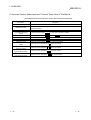
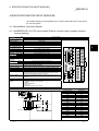
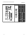
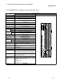
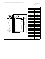
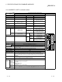
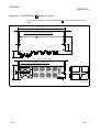
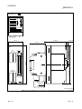
1.1 Features
The following are the features of the compact remote I/O module:
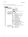
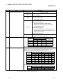
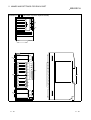
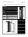
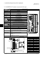
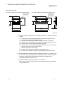
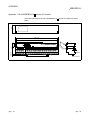
(1) The remote I/O module is reduced in size yet retains all the
functions of the conventional module
The conventional remote I/O module has furthermore been reduced in size.
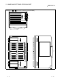
[External dimensions]
Compact remote I/O module
Module
model
name
AJ65SBTB1-8
Height
Width
Depth
AJ65SBTB1-16
AJ65SBTB2-8
AJ65SBTB2N-8
AJ65SBTC1-32
AJ65SBTC4-16
AJ65SBTCF1-32
AJ65SBTB3-8
AJ65SBTB32-8
Conventional remote I/O module
AJ65SBTB1-32
AJ65SBTB2-16
AJ65SBTB2N-16
AJ65SBTB3-16
AJ65SBTB32-16
AJ65BTB1-16
AJ65BTB2-16
151.9 (5.98)
197.5 (7.78)
50 (1.97)
87.3 (3.44)
118 (4.65)
40 (1.57)
AJ65BTC1-32
65 (2.56)
179 (7.04)
165.0 (6.5)
46 (1.81)
Unit : mm (in.)
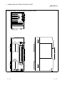
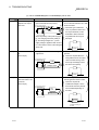
(2) More models in the compact remote I/O module lineup
Waterproof-type terminals have been added to the line of compact remote I/O
modules for the CC-Link systems. Along with the conventional terminal block
type and one-touch connector type modules and FCN connector type and
connector type and spring clamp terminal block type and sensor connector (eCON) type. Seven types are now available.
The 8-point type has been added to the conventional 16-point and 32-point
remote I/O modules, allowing the user to select a module that most suits his/her
objective and environment.
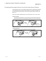
(3) 4-wire compact remote I/O module featuring easy connection of a
4-wire sensor
A 4-wire sensor can be easily connected via the common pin provided on each
plug without installing a relay terminal block.
For a 4-wire compact remote I/O module, one sensor is connected to each plug.
Therefore, sensors can be exchanged by plug, reducing work steps.
(4) Terminal block connection provides easy connection of 2-wire and
3-wire sensors or loads
Since the terminal block connection allows connection of 2-wire and 3-wire
sensors or loads, common connections are not needed and it makes connection
easier.
1-1
1-1
1 OVERVIEW
MELSEC-A
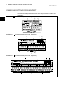
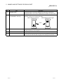
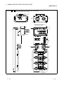
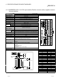
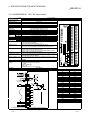
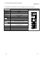
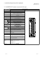
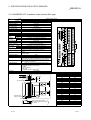
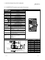
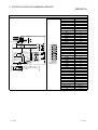
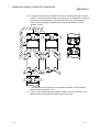
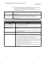
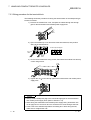
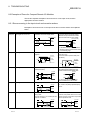
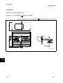
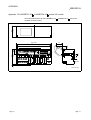
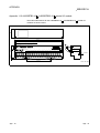
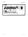
(5) Wiring work can be minimized
(a) Terminal-block module
The number of wiring steps can be dramatically reduced by adopting the use
of self-tightening screws on the terminal block.
(b) One-touch connector module, connector module
The number of wiring steps can be dramatically reduced by adopting use of
the pressure-displacement wire-connection method (soldering, peeling of
shield and screwing not necessary).
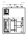
(c) FCN connector module
The number of wiring steps can be dramatically reduced by adopting 40-pin
connector for I/O part.
(d) Spring clamp terminal block module
The number of wiring steps can be dramatically reduced by adopting spring
clamps (screwing not necessary).
<Terminal-block module>
<One-touch connector module, connector module>
Self-tightening
screw is used
Round solderless terminal
Connector
The round solderless terminal can
be connected simply by loosening
the screw on the terminal block.
Soldering, peeling of the shield
and screwing are unnecessary.
Push in
<FCN connector module>>
Each of the individual wires
can be securely connected
simply by pressing the side
surface of the connector plug
after the wires are inserted
into the connector.
<Spring clamp terminal block type >
FCN connector
Square shaped hole
Circular shaped hole
Tool
1-2
1-2
1
1 OVERVIEW
MELSEC-A
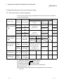
(6) Waterproof remote I/O modules with improved resistance against
water and oil
The waterproof remote I/O module, low profile waterproof remote I/O module
adopts a protection structure compatible with IP67, providing even safer usage in
areas in which water and oil are present.
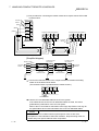
(7) Up to a maximum of 64 remote I/O modules can be connected
In the CC-Link system, a maximum of 64 remote I/O modules can be connected
per master station.
Since each remote I/O module occupies 32 points, a maximum of 2048 link
points can be set.
(8) Modules can be exchanged without stopping the CC-Link system
With the adoption of a two-piece terminal block for the CC-Link cable connection,
modules may be exchanged without stopping the CC-Link system.
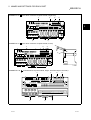
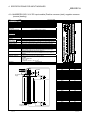
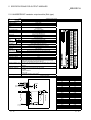
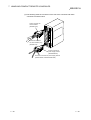
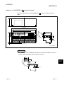
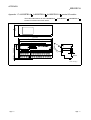
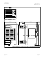
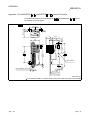
(9) Direct installation to the machine is feasible
The terminal-block remote I/O module may be installed directly to the machine,
since the charged area is protected by a finger protector in the upper area of the
terminal block.
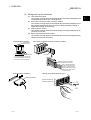
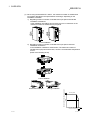
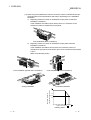
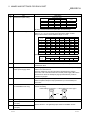
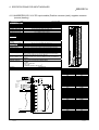
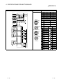
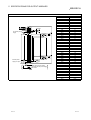
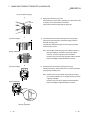
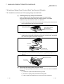
(10) The module can be installed in six orientations
The compact remote I/O module can be installed in six different orientations.
(Restrictions may apply to some installation orientations.)
The module can also be installed using the DIN rail.
Ceiling installation
DIN rail
Finger protector
Front installation
Horizontal installation
1-3
1-3
1 OVERVIEW
MELSEC-A
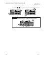
(11) Transistor output module with improved protection functions
The transistor output module is designed to achieve an even greater degree of
module protection by adopting short-circuit protection, overload protection,
thermal protection and overvoltage protection as standard. As a result, the PLC
system's reliability is further improved.
1-4
1-4
1 OVERVIEW
MELSEC-A
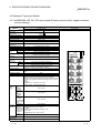
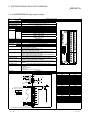
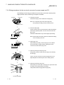
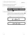
1.2 Identifying the Compact Remote I/O Module Type
The following shows how to identify the type of a compact remote I/O module:
AJ65 BT
I/O types
E:
I/O specifications
A:
100 V AC input
D : 24 V DC input
R:
Relay output
S:
Triac output
T : Transistor output
DT : 24 V DC input, transistor output complex
8: 8 points
16 : 16 points
32 : 32 points
A2 : With 8 M12 waterproof connector, Output,
2-wire type.
A4 : With 8 M12 waterproof connector, Input,
2 to 4-wire type.
A42 : With 8 M12 waterproof connector, Input,
2 to 4-wire type / Output, 2-wire type.
B1 : 1-wire terminal block
B2 : 2-wire terminal block
B32 : Terminal Block, Input, 3-wire type /
Output, 2-wire type.
C1 : 1-wire one-touch connector
C4 : 4-wire one-touch connector
CF1: 1-wire FCN connector
CU2: 2-wire one-touch connector
CU3: 3-wire one-touch connector
W4: 4-wire waterproof connector
S2: 2-wire spring clamp terminal block
S3: 3-wire spring clamp terminal block
S32: Spring clamp terminal block, Input, 3-wiretype /
Output, 2-wire type.
CE2: 2-wire sensor connector(e-CON)
CE3: 3-wire sensor connector(e-CON)
CE32: Sensor connector(e-CON), Input, 3-wire type /
Output, 2-wire type.
T : Twisted cable(CC-Link dedicated cable)
Number of I/O points
External load
connection method
Cable specification
Module type
1-5
F:
S:
V:
Source type
Low profile waterproof
Compact type
Connector type compact
1-5
1 OVERVIEW
MELSEC-A
1.3 Cautionary Notes when Selecting a Remote I/O Module
The following explains the cautionary notes and specifications that apply when
selecting a remote I/O module for use in the CC-Link system:
(1) This is a remote I/O module designed specifically for the CC-Link system.
Do not connect the module to other data-link systems, such as the
MELSECNET/MINI.
(2) 32 points are assigned per station for a compact remote I/O module.
For 16-point modules the 16 points in the second half and for 8-points module the
24 points in the second half remain empty but are not usable.
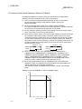
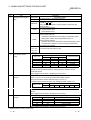
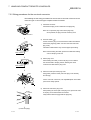
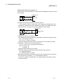
(3) For the maximum switching frequency when driving a load in the output module,
set to one second or more each for ON and OFF.
(4) When using a counter, a timer or the like that uses a DC/DC converter as the load
for a transistor output module having a maximum load current of 0.1A, a rush
current flows when the module is turned on and at fixed intervals during operation.
For this reason, malfunctions may occur if the average current is set. When the
above load is used, connect resistance or inductance in parallel to the load, or use
an output module having a large maximum load current in order to minimize the
effects of the rush current.
Resistance
Load
Inductance
Output
module
Load
Output
module
(5) Since the output modules of the AJ65SBTB1-16T1, AJ65BTB1-32T1,
AJ65SBTB1-8T1, AJ65SBTB2-8T1, AJ65SBTB2-16T1, AJ65SBTC1-32T1,
AJ65SBTB1-16DT2, AJ65SBTB1-32DT2, AJ65SBTB1-16DT3, AJ65SBTB132DT3, AJ65SBTB32-8DT2, AJ65SBTB32-16DT2, AJ65SBTC4-16DT2,
AJ65SBTC1-32DT2 and AJ65SBTC1-32DT3 are not equipped with a short
protection function, install an external short protection circuit.
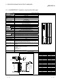
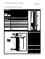
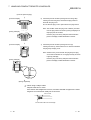
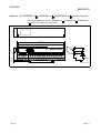
(6) When using the AJ65SBTC1-32D or AJ65SBTC1-32D1 input module, the
maximum number of simultaneous input points listed in the specifications will
change, depending on the ambient temperature.
The maximum number of simultaneous input points is shown in the diagram
below:
Dilating curve for the AJ65SBTC1-32D or AJ65SBTC1-32D1
Maximum number of simultaneous input points [%]
[%]
100
80
50
0
0
10
20
30
40
55
[°C]
Ambient temperature [°C]
1-6
1-6
1 OVERVIEW
MELSEC-A
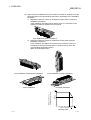
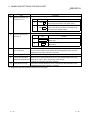
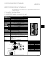
(7) When using the AJ65VBTCF1-32DT1, the maximum number of simultaneous
input points described in the specifications will change, depending on the
installation orientation.
1) Regarding maximum number of simultaneous input points unrestricted
installation orientations.
In the installation orientations shown below, there is no restriction on the
maximum number of simultaneous input points.
Front installation
2) Regarding maximum number of simultaneous input points restricted
installation orientations.
In the installation orientations shown below, The maximum number of
simultaneous input points will be 60%, when the circumambient temperature
is 55°C.
(Refer to the Derating Chart)
Front installation
Ceiling installation
Maximum number of simultaneous input points
Horizontal installation
Derating Chart
100
60
50
0
1-7
10 20 30 40 45
Ambient temperature
55
1-7
1 OVERVIEW
MELSEC-A
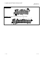
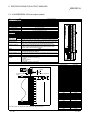
(8) When using the AJ65VBTS3-16D, the maximum number of simultaneous input
points described in the specifications will change, depending on the installation
orientation.
1) Regarding maximum number of simultaneous input points unrestricted
installation orientations.
In the installation orientation shown below, there is no restriction on the
maximum number of simultaneous input points.
A
J6
5VB
TS3-1
6D
C
D
2)
Front installation (Basic orientation)
Regarding maximum number of simultaneous input points restricted
installation orientations.
In the installation orientations shown below, the maximum number of
simultaneous input points will be 75% when the circumambient temperature
is 55°C.
(Refer to the Derating Chart)
J6
5V
BTS3
-16D
Front installation (Upside-down orientation)
J6
5V
BTS3
-16D
Front installation (Vertical orientation)
J6
5V
BTS3
-16D
Ceiling installation
Horizontal installation
[
]
Maximum number of
simultaneous input points
100
75
50
0
10
20
30
40
50 55
Ambient temperature [ ]
[
]
Derating Chart
1-8
1-8
1 OVERVIEW
MELSEC-A
(9) When using the AJ65VBTS3-32D, the maximum number of simultaneous input
points described in the specifications will change, depending on the installation
orientation.
1) Regarding maximum number of simultaneous input points unrestricted
installation orientations.
In the installation orientation shown below, there is no restriction on the
maximum number of simultaneous input points.
J6
5VB
TS3-1
6D
A
2)
Front installation (Basic orientation)
Regarding maximum number of simultaneous input points restricted
installation orientations.
In the installation orientations shown below, the maximum number of
simultaneous input points will be 69% (11 points/common) when the
circumambient temperature is 55°C.
(Refer to the Derating Chart)
J6
5V
BTS3
-16D
Front installation (Upside-down orientation)
Front installation (Vertical orientation)
J6
5V
BTS3
-16D
Horizontal installation
Ceiling installation
Maximum number of
simultaneous input points
[
]
100
75
69
(11 points)
50
0
10
20
30
40
50 55 [
Ambient temperature [ ]
]
Derating Chart
1-9
1-9
1 OVERVIEW
MELSEC-A
(10) When using the AJ65VBTS32-32DT, the maximum number of simultaneous input
points described in the specifications will change, depending on the installation
orientation.
1) Regarding maximum number of simultaneous input points unrestricted
installation orientations.
In the installation orientation shown below, there is no restriction on the
maximum number of simultaneous input points.
J65
VB
T3
S-1
6 D
A
2)
Front installation (Basic orientation)
Regarding maximum number of simultaneous input points restricted
installation orientations.
In the installation orientations shown below, the maximum number of
simultaneous input points will be 75% when the circumambient temperature
is 55°C.
(Refer to the Derating Chart)
J6
5VB
TS3-1
6D
Front installation (Upside-down orientation)
Front installation (Vertical orientation)
J6
5VB
TS3-1
6D
Ceiling installation
Horizontal installation
Maximum number of
simultaneous input points
[
]
100
75
50
0
10
20
30
40
50 55 [
Ambient temperature [ ]
]
Derating Chart
1 - 10
1 - 10
1 OVERVIEW
MELSEC-A
(11) When using the AJ65VBTCE3-16D, the maximum number of simultaneous input
points described in the specifications will change, depending on the installation
orientation.
1) Regarding maximum number of simultaneous input points unrestricted
installation orientations.
In the installation orientation shown below, there is no restriction on the
maximum number of simultaneous input points.
J65
VB
T3
S-1
6 D
C
D
2)
Front installation (Basic orientation)
Regarding maximum number of simultaneous input points restricted
installation orientations.
In the installation orientations shown below, the maximum number of
simultaneous input points will be 62.5% when the circumambient temperature
is 55°C.
(Refer to the Derating Chart)
J5V
6
BTS3
-16
D
Front installation (Upside-down orientation)
Front installation (Vertical orientation)
J5V
6
BTS3
-16
D
Ceiling installation
Horizontal installation
[
]
Maximum number of
simultaneous input points
100
75
62.5
50
0
10
20
30
40
50 55 [
Ambient temperature [ ]
]
Derating Chart
1 - 11
1 - 11
1 OVERVIEW
MELSEC-A
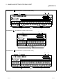
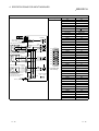
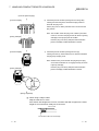
(12) The following chart shows the service life of the relay output module.
Applicable module: AJ65SBTB2N-8R, AJ65SBTB2N-16R
200
100
70
Service life (
10000 times)
50
30
20
100VDC to 120VDC
=7ms to 40ms
10
120VAC COS
=1
120VAC COS
=0.4
120VAC COS
=0.3
7
5
30VDC
3
(L/R) : Time constant
cos : Power factor
=7ms
120VAC COS
2
30VDC
=0.2
=40ms
1
0.1
0.2
0.3
0.5
0.7
1
2
3
5
Switching current (A)
1 - 12
1 - 12
1 OVERVIEW
MELSEC-A
POINT
(1) When using the module for the application in which the relay contact is
frequently switched, the relay life span should be considered. Therefore, it is
recommended to use a triac output module.
(2) The relay life curve shows the value based on actual use, which is not
guaranteed. Therefore, make sure to allow for a margin of error.
The relay life span differs according to the specifications as follows:
Rated switching voltage, current load
100 thousand operations
200V AC 1.5A, 240V AC 1A (COS =0.7)
100 thousand operations
200V AC 1A, 240V AC 0.5A (COS =0.35)
100 thousand operations
24V DC 1A, 100V DC 0.1A (L/R=7ms)
100 thousand operations
(3) Relay life is substantially affected by the load type and inrush current
characteristics.
The inrush current may cause the contact welding. Therefore, consideration
should be given to it as well as constant current.
(a) Inductive load
When the inductive load such as electromagnetic contactor or solenoid is
shut off, high counter-electromotive force is generated between the
contacting materials to produce an arc discharge. Consideration should be
made especially when the power factor is low, as it may decrease the life
period.
In addition, make sure to consider the contact melting, as the inrush current
equivalent to 5 to 15 times of constant current flows when the module is
powered on.
(b) Lamp load
Make sure to consider the contact melting, as the inrush current equivalent
to 10 to 15 times of constant current flows in the lamp circuit.
(c) Capacitive load
Make sure to consider the contact melting when a device such as condenser
is used in a load circuit, as the inrush current equivalent to 20 to 40 times of
constant current may flow in the circuit.
Also, pay full attention to the wire capacity if long length of wire is routed.
1 - 13
1 - 13
1 OVERVIEW
MELSEC-A
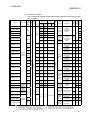
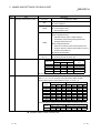
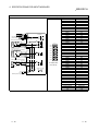
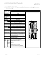
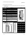
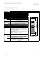
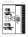
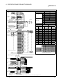
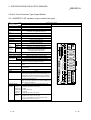
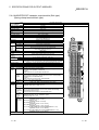
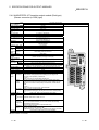
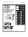
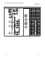
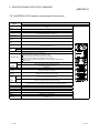
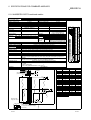
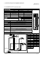
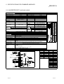
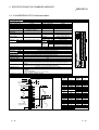
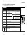
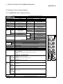
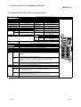
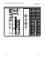
1.4 Specification List
Approx. 14 V or
7 mA
more
6 V or
less
1.5 ms or less
15 V or
more
3 V or
less
0.2 ms or less
14 V or
more
6 V or
less
1.5 ms or less
15 V or
more
3 V or
less
0.2 ms or less
32 points
16 points
AJ65SBTCF1-32D
32 points
AJ65SBTB3-8D
8 points
AJ65VBTCU3-8D1
AJ65VBTCU3-16D1
16 points
DC input
(Positive
common)
AJ65SBTB3-16D
AJ65SBTB2N-8A
8 points
AC input
AJ65SBTB2N-16A
AJ65FBTA4-16D
Approx. 14 V or
7 mA
more
6 V or
less
Approx. 15 V or
5 mA
more
3 V or
less
100 to
80 V or 30 V or
more
less
120 V AC
16 points
50/60 Hz
1.5 ms or less
0.2 ms or less
20 ms or less
Approx.
7 mA
DC input
(Positive
common)
AJ65VBTS3-16D
AJ65VBTCE3-8D
AJ65VBTCE3-16D
6 V or
less
32 points
Approx.
5 mA
8 points
16 points
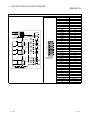
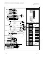
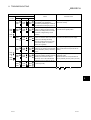
1 : 87.3 (3.44) (W) × 50 (1.97) (H) × 40 (1.57) (D) mm (in.)
2 : 118 (4.65) (W) × 50 (1.97) (H) × 40 (1.57) (D) mm (in.)
3 : 179 (7.05) (W) × 50 (1.97) (H) × 40 (1.57) (D) mm (in.)
4 : 184.7 (7.27) (W) × 57.9 (2.28) (H) × 86 (3.39) (D) mm (in.)
5 : 41 (1.61) (W) × 115 (4.53) (H) × 62 (2.44) (D) mm (in.)
6 : 60 (2.36) (W) × 115 (4.53) (H) × 62 (2.44) (D) mm (in.)
1 - 14
1
16 points
1 common
35 mA
40 mA
Reference
Input display
30 mA
4.1.1
4.1.2
2
45 mA
3-wire
terminal
block
3-wire
one-touch
connector
2-wire
terminal
block
32 points
1 common
4.1.3
4.1.4
1.5 ms or less
Spring
clamp
terminal
block 3wire type
Sensor
connector
(e-CON) 3wire type
50 mA
4.1.5
4.2.2
45 mA
2
35 mA
16 points
1 common
4.2.3
4.2.1
120
mA
4
4.3.1
32 points
1 common
45 mA
2
4.4.1
8 points
1 common
40 mA
2
4.1.8
16 points
1 common
45 mA
3
4.1.9
8 points
1 common
35 mA
5
4.5.1
16 points
1 common
40 mA
6
4.5.2
8 points
1 common
35 mA
2
4.1.6
16 points
1 common
40 mA
3
4.1.7
4.6.1
2 to 4-wire
waterproof
connector
14 V or
more
24VDC
DC input
(Positive
common)
4-wire
waterproof
connector
1.5 ms or less
DC input 16 points
AJ65FBTA4-16DE (Negative
common)
AJ65VBTS3-32D
1-wire
one-touch
connector
1-wire
FCN
connector
16 points
8 points
6 V or
less
8 points
1 common
3
4-wire
one-touch
connector
14 V or
more
External
dimensions
0.2 ms or less
1-wire
terminal
block
Common
connection
Internal
current
consumption
3 V or
less
External
connection
1.5 ms or less
LED display
AJ65SBTW4-16D
Input current
Approx. 15 V or
5 mA
more
24 V DC
AJ65SBTC4-16D
ON →
OFF
16 points
Photocoupler insulation
AJ65SBTC1-32D1
DC input (Positive/Negative common)
AJ65SBTC1-32D
ON
OFF
OFF →
voltage voltage
ON
6 V or
less
AJ65SBTB1-32D
AJ65SBTB1-32D1
Input response
time
Approx. 14 V or
7 mA
more
AJ65SBRB1-16D
AJ65SBTB1-16D1
Operation
voltage
8 points
Approx.5 mA
AJ65SBRB1-8D
Rated input
voltage
Model
Insulation
method
Input
format
No. of points
per module
Specification list for each compact remote I/O module is shown below.
(1) Input module
40 mA
16 points
1 common
7
4.6.2
35mA
8
4.5.3
40mA
9
4.5.4
8 points
1 common
30mA
10 4.5.5
16 points
1 common
35mA
11 4.5.6
7 : 60 (2.36) (W) × 200 (7.87) (H) × 48 (1.89) (D) mm (in.)
8 : 137 (5.39) (W) × 50 (1.97) (H) × 51.5 (2.03) (D) mm (in.)
9 : 222 (8.74) (W) × 50 (1.97) (H) × 51.5 (2.03) (D) mm (in.)
10 : 100 (3.94) (W) × 40 (1.57) (H) × 43.5 (1.71) (D) mm (in.)
11 : 100 (3.94) (W) × 50 (1.97) (H) × 45.5 (1.79) (D) mm (in.)
1 - 14
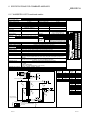
1 OVERVIEW
MELSEC-A
8 points
AJ65SBTB1-16T
Transistor 16 points
output 9
(sink type)
32 points
AJ65SBTB1-32T
AJ65SBTC1-32T
AJ65SBTB1-8T1
Transistor 16 points
output
12 32 points
AJ65SBTB1-32T1
(sink type)
AJ65SBTC1-32T1
32 points
Transistor 8 points
output 8
AJ65SBTB1-16TE (source type) 16 points
AJ65SBTB1-8TE
2.4 A
0.5 A
0.1 A
0.1 A
3.6 A
AJ65SBTB2N-16S
AJ65SBTCF1-32T
AJ65VBTCU2-8T
Triac output
14
3.6 A
24V DC
240V AC
16 points
32 points
Transistor
output 12 8 points
(sink type)
AJ65VBTCU2-16T
Transistor
output (sink
type)
Transistor 16 points
output
AJ65FBTA2-16TE
(source type)
AJ65FBTA2-16T
4A
2A
8A
100 to
240 V AC 0.6 A
50/60 Hz
8 points
2.4 A
4.8 A
3.2 A
0.1 A
Photocoupler insulation
AJ65SBTB2N-8S
16 points
2.4 A
0.8 A
1.6 A
10 ms
or less
12 ms
or less
1/2
1 ms cycle +
or less 1 ms or
less
0.5 ms
or less
1.5 ms
or less
1 ms
or less
1 ms
or less
0.5ms
or less
1.5ms
or less
12/24
V DC
1.0 A
4.0 A
AJ65VBTS2-16T
0.5 A
AJ65VBTS2-32T
AJ65VBTCE2-8T
Transistor 32 points
output 12
(sink type) 8 points
1 ms
or less
0.8 A
0.1 A
AJ65VBTCE2-16T
16 points
1.6 A
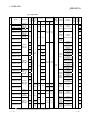
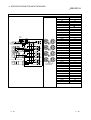
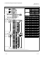
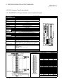
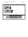
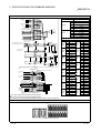
1 : 87.3 (3.44) (W) × 50 (1.97) (H) × 40 (1.57) (D) mm (in.)
2 : 118 (4.65) (W) × 50 (1.97) (H) × 40 (1.57) (D) mm (in.)
3 : 179 (7.05) (W) × 50 (1.97) (H) × 40 (1.57) (D) mm (in.)
4 : 184.7 (7.27) (W) × 57.9 (2.28) (H) × 86 (3.39) (D) mm (in.)
5 : 41 (1.61) (W) × 115 (4.53) (H) × 62 (2.44) (D) mm (in.)
6 : 60 (2.36) (W) × 115 (4.53) (H) × 62 (2.44) (D) mm (in.)
7 : 60 (2.36) (W) × 200 (7.87) (H) × 48 (1.89) (D) mm (in.)
8: 137 (5.39) (W) × 50 (1.97) (H) × 51.5 (2.03) (D) mm (in.)
1 - 15
1 ms
or less
Reference
Internal
current
consumption
External
dimensions
65 mA
3 5.1.6
60 mA
2 5.2.2
35 mA
1 5.1.7
50 mA
2 5.1.8
45 mA
2 5.1.9
55 mA
3 5.1.10
45 mA
2 5.1.11
55 mA
3 5.1.12
85 mA
2 5.1.13
120 mA
3 5.1.14
55 mA
2 5.1.15
85 mA
3 5.1.16
1-wire FCN 32 points
60 mA
connector 1 common
8 points
2-wire one35 mA
1 common
touch
16 points
connector 1 common 40 mA
Zener
diode
2 5.1.2
3 5.1.3
1-wire one- 32 points
1 common
touch
connector
8 points
1-wire
1 common
terminal
16 points
block
1 common
8 points
1 common
16 points
1 common
8 points
1 common
16 points
2-wire
1 common
terminal
8 points
block
1 common
None
16 points
1 common
8 points
1 common
C·R
32 points
Absorber
1 common
0.5 A
1 5.1.1
65 mA
1-wire one- 32 points
1 common 60 mA
touch
connector
8 points
35 mA
1 common
1-wire
16 points
terminal
50 mA
1 common
block
Zener
diode
2.4 A
Relay
insulatin
AJ65SBTB2N-16R
1.5 ms
or less
1.6 A
0.5 A
8 points
3.2 A
0.5 ms
or less
0.8 A
Transistor 8 points
output 12
AJ65SBTB2-16T1 (sink type) 16 points
Relay output
3.6 A
0.1 A
AJ65SBTB2-8T1
AJ65SBTB2N-8R
3.2 A
8 points
35 mA
1 common
16 points
50 mA
1 common
4.8 A
12/24
V DC
0.5 A
AJ65SBTB2-16T
3.6 A
2.4A
0.5 A
External
Common
connection connection
1-wire
terminal
block
4.8 A
Transistor 8 points
output 13
(sink type) 16 points
AJ65SBTB2-8T
ON →
OFF
Surge
suppression
OFF →
1 point 1 common
ON
8 points
AJ65SBTB1-16T1
Output response
time
Output
display
Rated
input
voltage
Maximum load
current
LED display
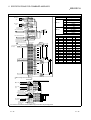
AJ65SBTB1-8T
Photocoupler insulation
Model
Insulation
method
Output
format
No. of points
per module
(2) Output module
2-wire
16 points
waterproof
1 common
connector
Spring
16 points
clamp
1 common
terminal
block 2-wire 16 points
1 common
type
8 points
Sensor
connector 1 common
(e-CON) 2- 16 points
wire type 1 common
2 5.2.1
1 5.1.4
2 5.1.5
2 5.3.1
5 5.4.1
6 5.4.2
50 mA
7 5.5.1
50 mA
7 5.5.2
45mA
8 5.4.3
60mA
9 5.4.4
35mA
45mA
10
11
5.4.5
5.4.6
9: 222 (8.74) (W) × 50 (1.97) (H) × 51.5 (2.03) (D) mm (in.)
10 : 100 (3.94) (W) × 40 (1.57) (H) × 43.5 (1.71)(D) mm (in.)
11 : 100 (3.94) (W) × 50 (1.97) (H) × 45.5 (1.79) (D) mm (in.)
12 : Leakage current when the transistor output is OFF (0.1 mA or less)
13 : Leakage current when the transistor output is OFF (0.25 mA or less)
14 : Leakage current when the triac output is OFF 1.5 mA rms or less
(100 V AC rms 60 Hz), 3 mA rms or less (200 V AC rms 60 Hz)
1 - 15
1 OVERVIEW
MELSEC-A
AJ65SBTC1-32DT1
16
points
AJ65SBTC1-32DT2
AJ65SBTC1-32DT3
AJ65SBTC4-16DT
8
points
AJ65SBTC4-16DT2
1.5 ms or less
14 V or 6 V or
more
less
1.5 ms or less
1.5 ms or less
AJ65SBTB1-16DT1
8
points
Approx. 15 V or 3 V or
5 mA
more
less
0.2 ms or less
16
points
Approx. 15 V or 3 V or
5 mA
more
less
0.2 ms or less
AJ65SBTB1-16DT2
8
points
Approx. 14 V or 6 V or
7 mA
more
less
1.5 ms or less
AJ65SBTB1-32DT2
16
points
Approx. 14 V or 6 V or
7 mA
more
less
1.5 ms or less
AJ65SBTB1-16DT3
8
points
Approx. 15 V or 3 V or
5 mA
more
less
0.2 ms or less
AJ65SBTB1-32DT3
16
points
Approx. 14 V or 6 V or
7 mA
more
less
1.5 ms or less
AJ65SBTB32-8DT
4
points
Approx. 14 V or 6 V or
7 mA
more
less
1.5 ms or less
AJ65SBTB32-16DT
8
points
Approx. 14 V or 6 V or
7 mA
more
less
1.5 ms or less
AJ65SBTB32-8DT2
4
points
Approx. 14 V or 6 V or
7 mA
more
less
1.5 ms or less
AJ65SBTB32-16DT2
8
points
Approx. 14 V or 6 V or
7 mA
more
less
1.5 ms or less
16
points
14 V or 6 V or
less
Approx. more
5 mA 15 V or 3 V or
more
less
24 V DC
Approx. 14 V or 6 V or
7 mA
more
less
Photocoupler insulation
16
points
AJ65VBTS32-32DT
14 V or 6 V or
more
less
AJ65VBTCE32-16DT
DC input
(sink type)
16
points
Approx.
5 mA
8
points
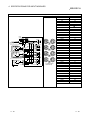
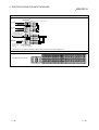
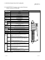
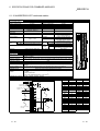
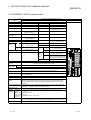
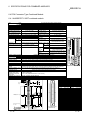
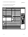
1 : 87.3 (3.44) (W) × 50 (1.97) (H) × 40 (1.57) (D) mm (in.)
2 : 118 (4.65) (W) × 50 (1.97) (H) × 40 (1.57) (D) mm (in.)
3 : 179 (7.05) (W) × 50 (1.97) (H) × 40 (1.57) (D) mm (in.)
4 : 184.7 (7.27) (W) × 57.9 (2.28) (H) × 86 (3.39) (D) mm (in.)
5 : 41 (1.61) (W) × 115 (4.53) (H) × 67 (2.64) (D) mm (in.)
1 - 16
1.5 ms or less
0.2 ms or less
Approx.
7 mA
AJ65VBTS32-16DT
4-wire
one-touch
connector
1.5 ms or less
AJ65SBTB1-32DT
8
points
6.2.5
2
6.2.6
1.5 ms or less
1.5 ms or less
DC input
(Positive/
Negative
AJ65VBTCF1-32DT1 common)
DC input
(Positive
AJ65FBTA42-16DT
common)
DC input
AJ65FBTA42-16DTE (Negative
common)
6.2.4
50 mA
0.2 ms or less
Approx. 14 V or 6 V or
7 mA
more
less
AJ65SBTCF1-32DT
1-wire
one-touch
connector
32 points
1 common
(shared with
output)
6.2.3
0.2 ms or less
8
points
AJ65SBTB1-32DT1
Common
connection
1.5 ms or less
AJ65SBTB1-16DT
DC input
(Positive
common)
External
connection
1.5 ms or less
Reference
OFF → ON →
ON
OFF
Internal
current
consumption
External
dimensions
OFF
voltage
6 V or
less
3 V or
less
6 V or
less
3 V or
less
6 V or
less
6 V or
less
Input response
time
Input display
ON
voltage
14 V or
more
15 V or
more
14 V or
more
15 V or
Approx. more
5 mA 14 V or
more
14 V or
more
AJ65SBTW4-16DT
Input side
Operation
voltage
4-wire
waterproof
connector
LED display
AJ65SBTC1-32DT
Input current
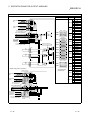
Input format
Insulation
method
Rated input
voltage
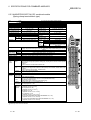
Model
No. of points
per module
Division
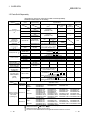
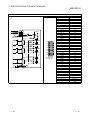
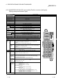
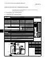
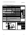
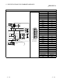
(3) Combined I/O module
In the combined I/O module, the input side and the output side are structure as a pair.
(a) Input side
16 points
1 common
(shared with
output)
16 points
1 common (shared
with output)
32 points
1 common (shared
with output)
16 points
1 common (shared
with output)
32 points
1 common (shared
1-wire
with output)
terminal
16 points
block
1 common (shared
with output)
32 points
1 common (shared
with output)
16 points
1 common (shared
with output)
32 points
1 common (shared
with output)
8 points
1 common (shared
with output)
16 points
Input 3-wire
1 common (shared
Output
with output)
2-wire
8 points
terminal 1 common (shared
with output)
block
16 points
1 common (shared
with output)
1-wire
one-touch
connector
16 points
1 common
6.2.1
40 mA
6.2.2
90 mA
4
6.3.1
50 mA
2
6.1.1
32 mA
3
6.1.2
55 mA
2
6.1.3
60 mA
3
6.1.4
50 mA
2
6.1.5
60 mA
3
6.1.6
55 mA
2
6.1.7
60 mA
3
6.1.8
45 mA
2
6.1.9
50 mA
3 6.1.10
45 mA
2 6.1.11
50 mA
3 6.1.12
2
6.4.1
5
6.5.1
50 mA
50 mA
8 points
2 to 4-wire
waterproof 1 common (Shared
with output)
connector
45 mA
6
16 points
1 common (shared 40mA
with output)
7
6.5.2
50mA
8
6.5.3
Sensor
16 points
connector
1 common (shared 40mA
(e-CON) 3with output)
wire type
9
6.5.4
Spring
clamp
terminal
block 3wire type
16 points
1 common
6.6.1
6.6.2
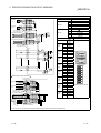
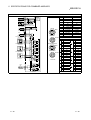
6 : 60 (2.36) (W) × 200 (7.87) (H) × 48 (1.89) (D) mm (in.)
7 : 137 (5.39) (W) × 50 (1.97) (H) × 51.5 (2.03) (D) mm (in.)
8 : 222 (8.74) (W) × 50 (1.97) (H) × 51.5 (2.03) (D) mm (in.)
9 : 100 (3.94) (W) × 50 (1.97) (H) × 41.5 (1.63) (D) mm (in.)
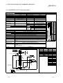
1 - 16
1 OVERVIEW
MELSEC-A
AJ65SBTC1-32DT1
AJ65SBTC1-32DT2
AJ65SBTC1-32DT3
AJ65SBTC4-16DT
AJ65SBTC4-16DT2
Transistor
output 11
(sink type)
Transistor
output 10
(sink type)
Transistor
output 11
(sink type)
Transistor
output 10
(sink type)
OFF → ON →
ON
OFF
6.2.3
16
points
0.1 A
1-wire
32 points
one-touch
1 common
connector (shared with input)
1.6 A
0.5 ms 1.5 ms
or less or less
4-wire
one-touch
connector
8
points
0.5 A
2.4 A
0.5 A
3.6 A
AJ65SBTB1-16DT1
8
points
AJ65SBTB1-32DT1
16
points
AJ65SBTB1-16DT2
8
points
2.4 A
16
points
3.6 A
AJ65SBTB1-16DT3
Transistor
output 10
(sink type)
16
points
AJ65SBTB1-32DT3
AJ65SBTB32-8DT
AJ65SBTB32-16DT
Transistor
output 11
(sink type)
AJ65SBTB32-8DT2
AJ65SBTB32-16DT2
AJ65SBTCF1-32DT
8
points
Transistor
output 10
(sink type)
4
points
2.4 A
24
V DC
Photocoupler insulation
AJ65SBTB1-32DT2
Output side
16
points
3.6 A
0.5 ms 1.5 ms
or less or less
2.4 A
0.5 A
3.6 A
1.2 A
8
points
2.4 A
4
points
1.2 A
8
points
2.4 A
16
points
12/24
0.1 A
V DC
0.5 ms 1.5 ms
or less or less
1.6 A
1 ms 1 ms
or less or less
AJ65VBTCF1-32DT1
AJ65FBTA42-16DT
AJ65FBTA42-16DTE
Transistor
output
(sink type)
Transistor
8
output
(source type) points
0.5 A
24
V DC
2.4 A
0.5 ms 1.5 ms
or less or less
1.0 A
4.0 A
AJ65VBTS32-16DT
0.5 A
AJ65VBTS32-32DT
AJ65VBTCE32-16DT
Transistor
output 10
(sink type)
16
points
12/24
V DC
8
points
24
V DC
1 ms 1 ms
or less or less
0.1 A
0.8 A
LED display
AJ65SBTB1-32DT
6.2.5
6.2.1
16 points
1 common
(shared with input)
6.2.2
4-wire
waterproof
connector
8
points
Transistor
output 11
(sink type)
6.2.4
6.2.6
AJ65SBTW4-16DT
AJ65SBTB1-16DT
Common
connection
Reference
1 point 1 common
External
connection
Internal current
consumption
External
dimensions
Output
response time
Output display
Surge
suppression
Maximum load
current
6.3.1
16 points
1 common (shared
with input)
32 points
1 common (shared
with input)
16 points
1 common
(shared with input)
32 points
1 common
1-wire
(shared with input)
terminal
16 points
block
1 common
(shared with input)
32 points
1 common
(shared with input)
16 points
1 common
(shared with input)
Zener
32 points
diode
1 common
(shared with input)
8 points
1 common
(shared with input)
16 points
Input 3-wire
1 common
Output
(shared with input)
2-wire
8 points
terminal
1 common
block
(shared with input)
16 points
1 common
(shared with input)
1-wire
FCN
connector
6.1.1
6.1.2
6.1.3
6.1.4
6.1.5
6.1.6
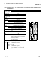
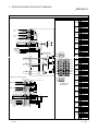
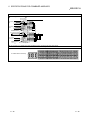
See input side
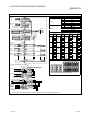
AJ65SBTC1-32DT
Output format
Rated input
voltage
Model
No. of points
per module
Insulation
method
Division
(b) Output side
6.1.7
—
6.1.8
6.1.9
6.1.10
6.1.11
6.1.12
6.4.1
16 points
1 common
2-wire
8 points
waterproof
1 common
connector (shared with input)
16 points
Spring
1 common
clamp
terminal (shared with input)
block 216 points
wire type
1 common
Sensor
16 points
connector
1 common
(e-CON) 2(shared with input)
wire type
6.5.1
6.6.1
6.6.2
6.5.2
6.5.3
6.5.4
10 : Leakage current when the transistor output is OFF (0.1 mA or less)
11 : Leakage current when the transistor output is OFF (0.25 mA or less)
1 - 17
1 - 17
1 OVERVIEW
MELSEC-A
1.5 Parts Sold Separately
The plugs for one-touch connector module are sold separately.
Please purchase them as necessary.
Mitsubishi model Part model name
name
(manufacturer)
Applicable cable core size
2
(mm )
Plug for
one-touch connector
1
A6CON-P214
A6CON-P220
A6CON-P514
A6CON-P520
One-touch
connector for
communication 2
One-touch
connector for power
supply and FG
2 4
Dustproof cap 1
Waterproof cap
1
FCN connector
Online connector for
communication 3
Online connector for
power supply 3
Terminal resister
attached one-touch
connector plug
(including 1)
Connector Type
Metal Installation
Fitting
(set of 5)
33104-6000FL
(3M)
33104-6100FL
(3M)
33104-6200FL
(3M)
33104-6300FL
(3M)
0.14 to 0.2
(AWG#26 to 24)
0.3 to 0.5
(AWG#22 to 20)
Maximum
rated
current (A)
φ 1.0 to 1.4
φ 1.4 to 2.0
Transparent
2
Yellow
φ 1.0 to 1.4
φ 1.4 to 2.0
0.5
φ 2.2 to 3.0
(AWG#20)
35505-6000A6CON-L5P
BOM GF (3M)
0.5
shielded cable
(AWG#20)
35505-6080-A00 0.75 (0.66 to 0.98) (AWG#18)
A6CON-PW5P
φ 2.2 to 3.0
GF (3M)
wire diameter 0.16 mm or more
Outer
insulation
layer
material:
A6CON-PW5P- 35505-6180-A00
φ 2.0 to 2.3
PVC (Heat-resistant vinyl)
SOD
GF(3M)
A6CAP-DC1
(AJ65SBTW -16 only)
Protection construction : IP67
A6CAP-WP1
(AJ65SBTW -16 only)
Protection of degree : IP67
A6CAP-WP2
(AJ65FBTA -16 only)
A6CON1
Soldering type (Straight-out type)
A6CON2
Crimp-contact type (Straight-out type)
A6CON3
Pressure-displacement type (Flat cable type)
A6CON4
Soldering type (Straight-out/diagonal-out type)
35720-L200-B00
A6CON-LJ5P
AK (3M)
35720-L200-A00
A6CON-PWJ5P
AK (3M)
A6CON-TR11
A6PLT-J65V1
A6PLT-J65V2
Red
3
Blue
One-touch connector plug with
terminal resister attached for
communication (110Ω)
For modules with a width of 41 mm
(AJ65VBTCU -8 , AJ65VBTCU -32 ,
AJ65VBTCU-68 )
10 M4 8 SWPW attached hole section screws
For modules with a width of 60 mm
(AJ65VBTCU -16 )
10 M4 8 SWPW attached hole section screws
Red
Gray
7
Blue
Applicable module
AJ65SBTB1-8D
AJ65SBTB1-8T
AJ65SBTB1-8TE
AJ65SBTB1-8T1
AJ65SBT-RPT
AJ65SBTB1-16D
AJ65SBTB1-16D1
AJ65SBTC1-32D
AJ65SBTC1-32D1
AJ65SBTC4-16D
AJ65SBTB3-8D
AJ65SBTB2-8A
AJ65SBTB2N-8A
Output :
AJ65SBTB1-16T
AJ65SBTC1-32T
AJ65SBTB1-16T1 AJ65SBTB2-8T
AJ65SBTB1-16TE
AJ65SBTB2-8R
AJ65SBTB2-8S
AJ65SBTB2N-8R
A6CVR-16
AJ65SBTB2N-8S
AJ65SBTB2-8T1
Combined :
AJ65SBTC1-32DT
AJ65SBTC1-32DT1 AJ65SBTC4-16DT AJ65SBTB1-6DT
AJ65SBTB1-16DT1 AJ65SBTB1-16DT2 AJ65SBTB32-8DT AJ65SBTC1-32DT2
AJ65SBTC1-32DT3 AJ65SBTC4-16DT2 AJ65SBTB1-16DT3 AJ65SBTB32-8DT2
Optical Repeater : AJ65SBT-RPS
AJ65SBT-RPG
Input :
AJ65SBTB1-32D
AJ65SBTB1-32D1
AJ65SBTB2-16A
AJ65SBTB2N-16A
AJ65SBTB3-16D
AJ65SBTB1-32T
AJ65SBTB1-32T1
AJ65SBTB2-16T
AJ65SBTB2-16R
A6CVR-32 Output :
AJ65SBTB2-16S
AJ65SBTB2N-16R
AJ65SBTB2N-16S AJ65SBTB2-16T1
Combined :
AJ65SBTB1-32DT
AJ65SBTB1-32DT1 AJ65SBTB1-32DT2 AJ65SBTB32-16DT
AJ65SBTB1-32DT3 AJ65SBTB32-16DT2
1 Mitsubishi's A6CON-P
, A6CAP1 includes 20 plugs.
2 Mitsubishi's A6CON- 5P includes 10 plugs.
3 Mitsubishi's A6CON- J5P includes 5 plugs.
4 Confirm the outer sheath diameter of the applicable cable and select the connector.
A6CVR-8
1 - 18
Applicable cable
outer diameter
(mm)
communication
line
Mitsubishi
model name
Protect cover for
compact remote
I/O module
(including 10)
Color of
the cover
Specifications
Input :
Output :
Repeater :
Input :
1 - 18
1 OVERVIEW
MELSEC-A
1.6 Recommended Connection Device List
1.6.1 Recommended connection devices for low profile waterproof remote I/O module
The following shows communication devices needed for use of the low profile
waterproof type remote I/O module (AJ65FBTA -16 ).
(1) Communications Module Waterproof Plug (Male / Female)
/ 5-pin can be used.
4-pin
(a) For LINK In Side (Female)
Model Name
Maker
ELKA 4012 PG9
ELKA 5012 PG9
CM02A-8DP5S(03)
ELWIKA 4012 PG9
ELWIKA 5012 PG9
HIRSCHMANN
HIRSCHMANN
DDK Ltd.
HIRSCHMANN
HIRSCHMANN
Specifications
Connection Cable Diameter
M12-4-pin Female Straight Type
M12-5-pin Female Straight Type
M12-4-pin Female Right-angle Type
M12-5-pin Female Right-angle Type
φ 6.0 to 8.0mm
φ 6.0 to 8.0mm
φ 8.0mm
φ 6.0 to 8.0mm
φ 6.0 to 8.0mm
(b) For LINK OUT Side (Male)
Model Name
ELST 4012 PG9
ELST 5012 PG9
CM02A-8DJ5P(03)
ELWIST 4012 PG9
ELWIST 5012 PG9
Maker
HIRSCHMANN
HIRSCHMANN
DDK Ltd.
HIRSCHMANN
HIRSCHMANN
Specifications
M12-4-pin Male Straight Type
M12-5-pin Male Straight Type
M12-4-pin Male Right-angle Type
M12-5-pin Male Right-angle Type
Connection Cable Diameter
φ 6.0 to 8.0mm
φ 6.0 to 8.0mm
φ 8.0mm
φ 6.0 to 8.0mm
φ 6.0 to 8.0mm
(2) Power Supply Module - Waterproof Plug (Female)
be used.
Model Name
ELKA 5012 PG7
ELKA 5012 PG9
CM02A-8DP5S(03)
ELWIKA 5012 PG7
ELWIKA 5012 PG9
Maker
Specifications
HIRSCHMANN
Connection Cable Diameter
M12-5-pin Female Straight Type
DDK Ltd.
HIRSCHMANN
5-pin only can
M12-5-pin Female Right-angle Type
φ 4.0 to 6.0mm
φ 6.0 to 8.0mm
φ 8.0mm
φ 4.0 to 6.0mm
φ 6.0 to 8.0mm
(3) I/O connector waterproof plug (male) 4-pin/5-pin can be used.
The plug for LINK OUT side (male) mentioned in Section (1) (b)
can be used.
(4) I/O Connector Y Branch Connector
Model Name
SAC-3P-M12Y
SAC-5P-M12Y
XS2R series
VA-4YG-2
Maker
Remarks
PHOENIX CONTACT
OMRON Corporation
CORRENS Corporation
(5) CC-Link Cable
Model Name
FA-CBL series
Cable with M12 Connector
1 - 19
Maker
MITSUBISHI ELECTRIC ENGINEERING Co.,Ltd
Shinwa Co.,Ltd
Remarks
CC-Link dedicated cable with waterproof
connector
The CA series cannot be used.
1 - 19
1 OVERVIEW
MELSEC-A
1.6.2 Recommended connection devices for low profile sensor connector (e-CON) remote
I/O module
The following shows communication devices needed for use of the sensor connector
(e-CON) remote I/O module (AJ65VBTCE ).
For how to wire the sensor connector (e-CON), refer to the catalog of the
corresponding maker.
(1) I/O sensor connector (e-CON) plug
1
Specifications
Applicable cable core
2
size (mm )
Applicable cable
outer diameter
(mm)
ECN-A014R
0.08 to 0.20 (AWG28 to 24)
φ 0.9 to 1.0
ECN-A004Y
0.20 to 0.30 (AWG24 to 22)
φ 1.0 to 1.15
ECN-A024BL
0.30 to 0.50 (AWG22 to 20)
φ 1.15 to 1.3
Model Name
Maker
ECN-M014R
(Mitsubishi Electric
ECN-M024Y
System Service
ECN-M0340R
Co., Ltd.)
φ 0.8 to 1.0
0.14 to 0.30 (AWG26 to 24)
φ 1.0 to 1.2
0.30 to 0.50 (AWG22 to 20)
1 - 20
φ 1.2 to 1.6
φ 1.6 to 2.0
ECN-M064GY
1 The ECN-
φ 1.0 to 1.2
φ 1.2 to 1.6
ECN-M044GN
ECN-M054BL
Maximum
rated
current (A)
2
Cover Color
Red
Yellow
Blue
Red
Yellow
Orange
Green
Blue
Gray
includes 20 plugs.
1 - 20
1 OVERVIEW
MELSEC-A
1.7 About the Generic, Abbreviated and Technical Terms Used in This Manual
The abbreviated and technical terms used in this manual are listed below:
Generic/abbreviated/
technical term
CC-Link
Master/local module
Compact remote I/O module
Conventional remote I/O
module
Remote I/O module
Description
Abbreviation of Control & Communications Link
Generic term for the AJ61BT11, A1SJ61BT11, AJ61QBT11 and A1SJ61QBT11 CC-Link system
master/local modules
Generic term for the AJ65SBT
-
Generic term for the AJ65BT
-
Generic term for the AJ65BT
-
CC-Link system compact remote I/O modules
CC-Link system remote I/O modules
/AJ65SBT
-
CC-Link system remote I/O modules
Input module
Generic term for the AJ65SBT
- A/D(1) remote I/O modules
Output module
Generic term for the AJ65SBT
- R/T /T1/TE remote I/O modules
Combined module
Generic term for the AJ65SBT
- DT(1) remote I/O modules
Waterproof type remote I/O
module
Generic term for the AJ65SBTW4-16
remote I/O modules
Low profile waterproof type
remote I/O module
Generic term for the AJ65FBTA -16
remote I/O modules
Spring clamp terminal block
type remote I/O module
Generic term for the AJ65VBTS -
remote I/O modules
Sensor connector (e-CON)
type remote I/O module
Generic term for the AJ65VBTCE -
1 - 21
remote I/O modules
1 - 21
1 OVERVIEW
MELSEC-A
MEMO
1 - 22
1 - 22
2 NAMES AND SETTINGS FOR EACH PART
MELSEC-A
2 NAMES AND SETTINGS FOR EACH PART
The names and settings for the components of the compact remote I/O module are
shown below:
AJ65SBTB1-8
(Terminal-block 8 point module, single-wire)
1)
2
3)
2)
STATION NO. B RATE
40 20 10 8 4 2 1 4 2 1
X0 1 2 3 4 5 6 7
ON
AJ65SBTB1-8D
DA
DG
DB
+24V
SLD
24G
X0
(FG)
X2
X1
X6
X5
COM
X7
COM
8)
6)
AJ65SBTB1-16
X4
X3
(Terminal-block 16 point module, single-wire)
1)
3)
X0 1 2 3 4 5 6 7
X8 9 A B C D E F
2)
STATION NO.
B RATE
40 20 10 8 4 2 1 4 2 1
ON
AJ65SBTB1-16D
DA
DG
DB
+24V
24G
SLD
X0
(FG)
X2
X1
X4
X3
X6
X5
XA
X9
XC
XB
XE
XD
COM
XF
COM
8)
6)
AJ65SBTB1-32
X8
X7
(Terminal-block 32 point module, single-wire)
1)
X0 1 2 3 4 5 6 7
3)
X8 9 A B C D E F
X10 11 12 13 14 15 16 17
X1819 1A1B1C1D1E 1F
2)
STATION NO.
B RATE
40 20 10 8 4 2 1 4 2 1
ON
AJ65SBTB1-32D
DA
DB
DG
+24V
SLD
24G
X0
(FG)
X2
X1
X4
X3
X6
X5
X8
X7
XA
X9
XC
XB
XE
XD
X10
XF
X12
X11
X14
X13
X16
X15
X18
X17
X1A
X19
X1C
X1B
X1E
X1D
COM
X1F
COM
6)
8)
2-1
8)
2-1
2 NAMES AND SETTINGS FOR EACH PART
AJ65SBTC1-32
MELSEC-A
(One-touch connector 32 point module, single-wire)
1)
4)
X0 1 2 3 4 5 6 7
X8 9 A B C D E F
3)
AJ65SBTC1-32D
DG
DB
+24V
SLD
X0
X1
X2
X3
24G
(FG)
X4
X5
X6
X7
ON
AJ65SBTC4-16
X10-X1F
X8
X9
XA
XB
8)
6)
STATION NO.
B RATE
40 20 10 8 4 2 1 4 2 1
X0-XF
X10 11 12 13 14 15 16 17 X18 19 1A 1B1C1D1E 1F
DA
2)
XC
XD
XE
XF
X10
X11
X12
X13
X14
X15
X16
X17
X18
X19
X1A
X1B
X1C
X1D
X1E
X1F
7)
2
COM
COM
6)
(One-touch connector 16 point module, 4-wire)
1)
3)
X0 1 2 3 4 5 6 7
Y8 9 A B C D E F
2)
STATION NO.
B RATE
40 20 10 8 4 2 1 4 2 1
ON
5)
AJ65SBTC4-16DT
DA
DG
DB
+24V
SLD
24G
(FG)
X0
Y8
+24V
24G
X1
Y9
+24V
24G
X2
YA
+24V
24G
X3
YB
+24V
24G
X4
YC
+24V
24G
X5
YD
+24V
24G
X6
YE
+24V
24G
X7
YF
+24V
24G
COM-
6)
6)
8)
AJ65SBTCF1-32
CTL+
7)
(Terminal block 32 point module, single - wire FCN 40-pin connector)
1)
4)
3)
2)
STATION NO. B RATE
40 20 10 8 4 2 1 4 2 1
X0-XF
ON
MITSUBISHI
AJ65SBTCF1-32D
X10-X1F
X10 X11 X12 X13 X14 X15 X16 X17 X18 X19 X1A X1B X1C X1D X1E X1F NC NC NC NC
X0 X1 X2 X3 X4 X5 X6 X7 X8 X9 XA XB XC XD XE XF NC NC COMCOM
6)
2-2
8)
7)
2-2
2 NAMES AND SETTINGS FOR EACH PART
AJ65SBTB2N-8
MELSEC-A
(Terminal block 8 point module, 2-wire)
3)
MITSUBISHI
2)
1)
PW L RUN L ERR X0 1 2 3 4 5 6 7
STATION NO.
B RATE
40 20 10 8 4 2 1 4 2 1
AJ65SBTB2N-8A
ON
DA
DG
DB
+24V
SLD
24G
(FG)
X0
X1
X2
X3
X4
X5
X6
X7
COM A
COM B COM B COM B COM B COM B COM B COM B COM B COM B
6)
AJ65SBTB2N-16
8)
(Terminal block 16 point module, 2-wire)
3)
MITSUBISHI
2)
1)
PW L RUN L ERR X0 1 2 3 4 5 6 7
STATION NO.
B RATE
40 20 10 8 4 2 1 4 2 1
AJ65SBTB2N-16A
8 9 A B C D E F
ON
DA
DB
DG
+24V
SLD
24G
X0
X1
X2
X3
X4
X5
X6
X7
X8
X9
XA
XB
XC
XD
XE
XF
COM A
COM B COM B COM B COM B COM B COM B COM B COM B COM B COM B COM B COM B COM B COM B COM B COM B COM B
(FG)
8)
AJ65SBTB2-8
6)
8)
(Terminal block 8 point module, 2-wire)
3)
1)
PW L RUN L ERR Y0 1 2 3 4 5 6 7
2)
STATION NO.
B RATE
40 20 10 8 4 2 1 4 2 1
ON
MITSUBISHI
DA
DB
DG
+24V
SLD
A J65SBTB2-8T
24G
(FG)
Y0
Y1
COM
Y2
COM
6)
2-3
Y3
COM
Y4
COM
Y5
COM
Y6
COM
Y7
COM
DC24V
COM DC24G
8)
2-3
2 NAMES AND SETTINGS FOR EACH PART
AJ65SBTB2-16
MELSEC-A
(Terminal block 16 point module, 2-wire)
3)
2)
STATION NO.
B RATE
1)
PW L RUN L ERR Y0 1 2 3 4 5 6 7
Y8 9 A B C D E F
40 20 10 8 4 2 1 4 2 1
ON
MITSUBISHI
DA
DG
DB
+24V
SLD
A J65SBTB2-16T
24G
Y0
(FG)
Y1
COM
Y2
COM
Y4
Y3
COM
COM
Y5
COM
8)
AJ65SBTB3-8
Y6
COM
Y7
COM
Y8
COM
Y9
COM
YA
COM
YB
COM
YC
COM
YD
COM
YE
COM
YF
COM
DC24V
COM DC24G
8)
6)
(Terminal block 8 point module, 3-wire)
3)
1)
PW L RUN L ERR X0 1 2 3 4 5 6 7
2)
STATION NO.
B RATE
40 20 10 8 4 2 1 4 2 1
ON
MITSUBISHI
DA DG
+24V
DB
SLD
AJ65SBTB3-8D
24G
(FG)
X0
X1
COMA
X2
X3
X4
X5
X6
X7
DC24A
COMB COMA COMB COMA COMB COMA COMB DC24B
6)
AJ65SBTB3-16
8)
(Terminal block 16 point module, 3-wire)
1)
3)
PW L RUN L ERR X0 1 2 3 4 5 6 7
X8 9 A B C D E F
STATION NO.
40 20 10 8 4 2
2)
1
B RATE
4 2 1
ON
MITSUBISHI
DA DG
+24V
DB
SLD
A J65SBTB3-16D
24G
(FG)
X0
X1
X2
X4
X5
X6
X7
X8
Y9
YA
XB
XC
XD
XE
XF
DC24A
X3
COMA COMB COMA COMB COMA COMB COMA COMB COMA COMB COMA COMB COMA COMB COMA COMB DC24B
8)
2-4
6)
8)
2-4
2 NAMES AND SETTINGS FOR EACH PART
AJ65SBTB32-8
MELSEC-A
(Terminal block 8 point module, 3-wire input, 2-wire output)
3)
1)
PW L RUN L ERR X0 1 2 3 Y8 9 A B
2)
STATION NO.
B RATE
40 20 10 8 4 2 1 4 2 1
ON
MITSUBISHI
DA
DG
DB
+24V
SLD
A J65SBTB32-8DT
24G
X0
(FG)
X1
COM+
X2
COM-
6)
AJ65SBTB32-16
X3
COM+
COM-
Y8
Y9
YA
YB
DC24V
COM+ COM+ COM+ COM+ DC24G
8)
(Terminal block 16 point module, 3-wire input, 2-wire output)
1)
PW L RUN L ERR X0 1 2 3 4 5 6 7
Y8 9 A B C D E F
3)
2)
STATION NO.
40 20 10 8 4 2 1
B RATE
4 2 1
ON
MITSUBISHI
DA DG
+24V
DB
SLD
A J65SBTB32-16DT
24G
(FG)
X0
X1
COM+
COM-
X2
X4
X5
X6
X7
Y8
Y9
YA
YB
YC
YD
YE
YF
DC24V
X3
COM+
COM- COM+
COMCOM+ COM- COM+ COM+ COM+ COM+ COM+ COM+ COM+ COM+ DC24G
8)
2-5
6)
2-5
2 NAMES AND SETTINGS FOR EACH PART
No.
1)
MELSEC-A
Item
Description
Operating status indicator LEDs
LED name
Confirmation details
On: Power supply on.
PW
Off: Power supply off.
On: Normal communication.
L RUN
Off: Communication cutoff.
(time expiration error)
On: Communication data error.
Flicker at regular intervals:
Indicates that the station number setting or
transmission speed setting switch position was
changed while power is on.
L ERR
Flicker at irregular intervals:
When the connection of the terminal resistor was
forgotten; when the cable for the module, CC-Link is
receiving noise influence.
Off: Normal communication.
2)
X0 to 1F
On: INPUT ON, Off: INPUT OFF.
Y0 to 1F
On: OUTPUT ON, Off: OUTPUT OFF.
Transmission speed setting
Setting switch status
4
2
1
Transmission
speed
0
OFF
OFF
OFF
156 kbps
1
OFF
OFF
ON
625 kbps
2
OFF
ON
OFF
2.5 Mbps
3
OFF
ON
ON
5.0 Mbps
4
ON
OFF
OFF
10 Mbps
Setting value
Be sure to set the transmission speed within the above range.
3)
Station number setting switches
Select "10," "20" or "40" to set the ten's place of the station number.
Select "1," "2," "4" or "8" to set the one's place of the station number.
Always set the station number within the range of 1 to 64. (*1)
Ten's place
One's place
Station
number
40
20
10
8
4
2
1
1
2
3
OFF
OFF
OFF
OFF
OFF
OFF
OFF
OFF
OFF
OFF
OFF
OFF
OFF
OFF
OFF
OFF
ON
ON
ON
OFF
4
:
OFF
:
OFF
:
OFF
:
OFF
:
OFF
:
OFF
:
OFF
:
10
11
OFF
OFF
OFF
OFF
ON
ON
OFF
OFF
OFF
OFF
OFF
OFF
OFF
ON
:
64
:
ON
:
ON
:
OFF
:
OFF
:
ON
:
OFF
:
OFF
(Example) Set the switches as below when setting the station number to 32:
Station
number
40
Ten's place
20
10
8
One's place
4
2
1
32
OFF
ON
ON
OFF
OFF
ON
OFF
1 Duplicate station number cannot be set.
2-6
2-6
2 NAMES AND SETTINGS FOR EACH PART
No.
4)
MELSEC-A
Item
I/O display switch
Description
Setting the switch to X/Y0-X/YF displays the on/off status of X/Y0-X/YF.
Setting the switch to X/Y10-X/Y1F displays the on/off status of X/Y10-X/Y1F.
5)
Sink/source switch
Switches the input format between sink and source.
(For AJ65SBTC1-16D only)
Open the unit top cover to perform the setting.
<When setting for sink type>
<When setting for source type>
SOURCE
SOURCE
Switch
SINK
SINK
6)
Terminal block
A terminal block for connection to the power supply of compact remote I/O
7)
Connector
An input signal connector
8)
Hook for DIN rail
Hook to install the module to the DIN rail. When installing, push on the center
module, transmission and I/O signals.
line of the hook for DIN rail with a finger tip until a clicking sound is heard.
2-7
2-7
2 NAMES AND SETTINGS FOR EACH PART
AJ65SBTW4-16
MELSEC-A
(waterproof connector 16 point module, single wire,)
4)
7)
2)
3)
9)
SINK
SOURCE
6)
10)
LINK CABL
8)
LINK CABL
IN
1)
PW
POWER CABL
OUT POWER CABL
CON1
CON3
CON5
CON7
CON2
CON4
CON6
CON8
L RUN
L ERR.
Y8
Y9
YA
YB
YC
YD
YE
YF
X0
X1
X2
X3
X4
X5
X6
X7
STATION NO.
MITSUBISHI
AJ65SBTW4-16DT
5)
No.
1)
Item
Operating status indicator LEDs
Description
LED name
PW
Confirmation details
On: Power supply on.
Off: Power supply off.
On: Normal communication.
L RUN
Off: Communication cutoff.
(time expiration error)
On: Communication data error.
Flicker at regular intervals:
Indicates that the station number setting or
transmission speed setting switch position was
L ERR
changed while power is on.
Flicker at irregular intervals:
When the connection of the terminal resistor was
forgotten; when the cable for the module, CC-Link is
receiving noise influence.
Off: Normal communication.
2-8
X0 to 1F
On: INPUT ON, Off: INPUT OFF.
Y0 to 1F
On: OUTPUT ON, Off: OUTPUT OFF.
2-8
2 NAMES AND SETTINGS FOR EACH PART
No.
2)
MELSEC-A
Item
Description
Transmission speed setting
Setting switch status
4
2
1
Transmission
speed
0
1
OFF
OFF
OFF
OFF
OFF
ON
156 kbps
625 kbps
2
OFF
ON
OFF
2.5 Mbps
3
OFF
ON
ON
5.0 Mbps
4
ON
OFF
OFF
10 Mbps
Setting value
3)
Station number setting switches
Be sure to set the transmission speed within the above range.
Select "10," "20" or "40" to set the ten's place of the station number.
Select "1," "2," "4" or "8" to set the one's place of the station number.
Always set the station number within the range of 1 to 64.
Ten's place
One's place
Station
number
40
20
10
8
4
2
1
1
2
OFF
OFF
OFF
OFF
OFF
OFF
OFF
OFF
OFF
OFF
OFF
ON
ON
OFF
3
OFF
OFF
OFF
OFF
OFF
ON
4
OFF
OFF
OFF
OFF
OFF
OFF
OFF
:
10
:
OFF
:
OFF
:
ON
:
OFF
:
OFF
:
OFF
:
OFF
11
:
OFF
:
OFF
:
ON
:
OFF
:
OFF
:
OFF
:
ON
:
64
ON
ON
OFF
OFF
ON
OFF
OFF
(Example) Set the switches as below when setting the station number to 32:
Station
number
40
Ten's place
20
10
8
One's place
4
2
1
32
OFF
ON
ON
OFF
OFF
ON
OFF
The terminal block for connecting the I/O module power supply and
transmission cable.
4)
Terminal block
5)
Through pipe for transmission and The through pipe used to connect the transmission and module power-supply
cables to the terminal block.
module power-supply cables
Open the module top cover and remove the terminal block to perform
connection work of the transmission and module power-supply cables to the
terminal block. Attach the waterproof plugs provided with the product to
unused through pipes.
Waterproof connector for I/O wire A connector (waterproof) for I/O signals.
Attach the optional dustproof caps (A6CAP-DC1) to unused waterproof
connectors.
Selects the input format from sink or source. Open the module top cover to
Sink/source switch
perform the setting.
(For AJ65SBTW4-16D only)
6)
7)
< When setting for sink type > < When setting for source type >
SOURCE
SOURCE
Switch
SINK
8)
Metal fitting
Module top-cover installation
screw (M3)
9)
10)
Module front-cover installation
screw (M3)
2-9
SINK
Module terminal for FG
Refer to Section 7.1 for tightening torque value for installation screws.
2-9
2 NAMES AND SETTINGS FOR EACH PART
AJ65VBTCU
-8
MELSEC-A
(One-touch connector 8 points module)
40
20
10
8
4
2
1
4
2
3)
2)
1
AJ65VBTCU3-8D1
5)
CON
A
CON
B
X0
PW
L RUN
X1
L ERR
X2
X3
7)
X4
0
1
2
3
4
5
6
7
1)
8)
X5
X6
X7
6)
CON
C
CON
D
2 - 10
2 - 10
2 NAMES AND SETTINGS FOR EACH PART
AJ65VBTCU
-16
MELSEC-A
(One-touch connector 16 points module)
40
20
10
8
4
2
1
4
2
1
3)
2)
AJ65VBTCU3-16D1
CON
A
5)
CON
B
PW
L RUN
L ERR
0
1
2
3
4
5
6
7
7)
X0 to X7
X8 to XF
1)
8)
8
9
A
B
C
D
E
F
CON
C
6)
CON
D
2 - 11
2 - 11
2 NAMES AND SETTINGS FOR EACH PART
MELSEC-A
AJ65VBTCF1-32DT1 (1-wire FCN connector 32 points module)
40
20
10
8
4
2
1
4
2
1
3)
2)
AJ65VBTCF1-32DT1
LINK
CON.A CON.B
X0
to
XF
Y10
to
Y1F
4)
PW
L RUN
5)
L ERR
0
1
2
3
4
5
6
7
PW/AUX.
CON.C CON.D
8)
1)
8
9
A
B
C
D
E
F
6)
7)
2 - 12
2 - 12
2 NAMES AND SETTINGS FOR EACH PART
No.
1)
MELSEC-A
Item
Description
Operating status indicator LEDs
LED name
Confirmation details
On: Power supply on.
PW
Off: Power supply off.
On: Normal communication.
L RUN
Off: Communication cutoff.
(time expiration error)
On: Communication data error.
Flicker at regular intervals:
Indicates that the station number setting or
transmission speed setting switch position was
changed while power is on.
L ERR
Flicker at irregular intervals:
When the connection of the terminal resistor was
forgotten; when the cable for the module, CC-Link is
receiving noise influence.
Off: Normal communication.
2)
X0 to 1F
On: INPUT ON, Off: INPUT OFF.
Y0 to 1F
On: OUTPUT ON, Off: OUTPUT OFF.
Transmission speed setting
Setting switch status
4
2
1
Transmission
speed
0
OFF
OFF
OFF
156 kbps
1
OFF
OFF
ON
625 kbps
2
OFF
ON
OFF
2.5 Mbps
3
OFF
ON
ON
5.0 Mbps
4
ON
OFF
OFF
10 Mbps
Setting value
Be sure to set the transmission speed within the above range.
3)
Station number setting switches
Select "10," "20" or "40" to set the ten's place of the station number.
Select "1," "2," "4" or "8" to set the one's place of the station number.
Always set the station number within the range of 1 to 64. (*1)
Ten's place
One's place
Station
number
40
20
10
8
4
2
1
1
2
3
OFF
OFF
OFF
OFF
OFF
OFF
OFF
OFF
OFF
OFF
OFF
OFF
OFF
OFF
OFF
OFF
ON
ON
ON
OFF
4
:
OFF
:
OFF
:
OFF
:
OFF
:
OFF
:
OFF
:
OFF
:
10
11
OFF
OFF
OFF
OFF
ON
ON
OFF
OFF
OFF
OFF
OFF
OFF
OFF
ON
:
64
:
ON
:
ON
:
OFF
:
OFF
:
ON
:
OFF
:
OFF
(Example) Set the switches as below when setting the station number to 32:
Station
number
40
Ten's place
20
10
8
One's place
4
2
1
32
OFF
ON
ON
OFF
OFF
ON
OFF
1 Duplicate station number cannot be set.
2 - 13
2 - 13
2 NAMES AND SETTINGS FOR EACH PART
No.
4)
Item
I/O display switch
MELSEC-A
Description
Setting the switch to X/Y0-X/YF displays the on/off status of X/Y0-X/YF.
Setting the switch to X/Y10-X/Y1F displays the on/off status of X/Y10-X/Y1F.
5)
One-touch connector for
A one-touch connector for connection of the communication line
communication
When carrying out wiring, connect two optional one-touch connector plugs for
communication (A6CON-L5P) at top and bottom.
When changing the module online, connect the optional online connectors
(A6CON-LJ5P) between the connector and plugs.
When using the module at either end of the CC-Link system, fit the optional
one-touch connector plug with termination resistor (110Ω) (A6CON-TR11).
6)
One-touch connector for power
A one-touch connector for connection of the module power supply line, I/O
supply and FG
power supply line and FG
When carrying out jumper wiring, connect two optional one-touch connector
plugs for power supply/FG at top and bottom. Two different types (A6CONPW5P, A6CON-PW5P-SOD) are available as the one-touch connector plugs
for power supply and FG.
When not carrying out jumper wiring, also connect the plugs (for safety and
dust prevention).
When changing the module online, connect the optional online connectors
(A6CON-PWJ5P) between the connector and plugs.
7)
Connector
8)
Hook for DIN rail
An input signal connector
Hook to install the module to the DIN rail or connector type Metal installation
fitting (option). When installing, push on the center line of the hook for DIN rail
with a finger tip until a clicking sound is heard.
2 - 14
2 - 14
2 NAMES AND SETTINGS FOR EACH PART
AJ65FBTA -16
MELSEC-A
(Low profile waterproof connector 16 points module)
Connector for connection to main module
4)
TERMINATION
110
130
5)
b
5)
a
ON
1 2
Communication adapter (front)
Communication adapter (back)
Connector for connection to
communication adapter
10)
3)
8)
2)
ON
40 20 10 8 4 2 1 4 2 1
STATION NO B RATE
Communication
adapter
AJ65FBTA42-16DTE
PROTECT
Y8
Y9
YA
YB
YC
YD
YE
YF
1)
6)
d
6)
c
Y
Y
Y
Y
7)
7)
Y
Y
Y
Y
Storage sheet
2 - 15
2 - 15
2 NAMES AND SETTINGS FOR EACH PART
No.
1)
Item
Operating status indicator
LEDs
Description
LED name
POWER
PROTECT
L RUN
L ERR.
X0 to X7/
Y0 to YF/
X0 to X7,
Y0 to YF
2)
MELSEC-A
Confirmation details
On: Power supply on. Off: Power supply off.
Lights up when the output section protection function is working.
(AJ65FBTA -16 TE)
(During the protect operation, fuse interruption is searched in the
master unit side.)
On: Normal communication.
Off : Communication cutoff.
(time expiration error)
On: Communication data error.
Flicker at regular intervals:
Indicates that the station number setting or transmission speed
setting switch position was changed while power is on.
Flicker at irregular intervals:
When the connection of the terminal resistor was forgotten; when
the cable for the module, CC-Link is receiving noise influence.
Off: Normal communication.
On: INPUT ON, Off: INPUT OFF.
On: OUTPUT ON, Off: OUTPUT OFF.
Trans-mission speed
setting
Setting switch status
Setting value
0
1
2
3
4
4
2
1
OFF
OFF
OFF
OFF
ON
OFF
OFF
ON
ON
OFF
OFF
ON
OFF
ON
OFF
Transmission speed
156 kbps
625 kbps
2.5 Mbps
5.0 Mbps
10 Mbps
Be sure to set the transmission speed within the above range.
Remove the communication adapter on the top part of the module to set the
transmission speed.
(When shipped from the factory, all settings are set to OFF.)
3)
Station number setting
Select "10", "20" or "40" to set the ten's place of the station number.
switches
Select "1","2","4" or "8" to set the one's place of the station number.
Always set the station number within the range of 1 to 64. (*1)
(Example) Set the switches as below when setting the station number to 10:
Station number
10
Ten's place
One's place
40
20
10
8
4
2
1
ON
OFF
ON
OFF
OFF
OFF
OFF
Remove the communication adapter on the top part of the module to set the station
number.
(When shipped from the factory, all settings are set to OFF.)
4)
Terminal resistor select
The terminal register can be turned to the ON setting by using the select switch.
switches
DIP switch 1
DIP switch 2
Contents
OFF
ON
OFF
ON
OFF
OFF
ON
ON
No terminal resistance
110Ω resistor ON
130Ω resistor ON
Setting prohibited
(When shipped from the factory, all settings are set to OFF.)
*1 Duplicate station number cannot be set.
2 - 16
2 - 16
2 NAMES AND SETTINGS FOR EACH PART
No.
5)
Item
MELSEC-A
Description
Waterproof connector for
transmission line *2
Silk
a
LINK IN
Contents
Connector for connecting the transmission line from
the IN side (master station side). (Male 4 pins)
Connector for connecting the transmission line from
b
LINK OUT
the OUT side. Be sure to attach the waterproof cap
when not in use. (Female 5 pins)
6)
Waterproof connector for
power line *2
7)
Silk
c
UNIT POWER
d
AUX.
Contents
Connector for supplying power to the module.
(Male 5 pins)
Connector for supplying power to a load, etc.
(Male 5 pins)
Waterproof connector for
Waterproof connector for connection input signal. (Female 5 pins)
input connection*2
Be sure to attach waterproof cap A6CAP-WP2 (sold separately) when not in use.
(Tightening torque range: 0.29 N/m to 0.34 N/m.)
8)
FG metal fitting
For module FG terminal (tightening torque range: 0.78 N/m to 1.18 N/m)
9)
Screw for communication
Use this screw for removal/attachment of the communication adapter to the main
adapter removal/attachment module when online or when changing the switch settings.
(Tightening torque range: 0.42 N/m to 0.58 N/m).
10)
Module attachment hole
Screw hole for module attachment. 2-4.5 X 6 length hole (M4 attachment screw)
(Tightening torque range: 0.78 N/m to 1.18 N/m).
*2: Waterproof connector (based on IEC947-5-2, M12 type)
2 - 17
2 - 17
2 NAMES AND SETTINGS FOR EACH PART
AJ65VBTS -16
(Spring clamp terminal block type 16 points module)
1)
1 2 4 1 2 4 8 1020 40
CON A
10)
PW L RUN L ERR.
AJ65VBTS3-16D
0 1 2 3 4 5 6 7
8 9 A B C D E F
NC
B
9) 10)
C
X0
X1
X2 X3
X4
X5
X6
X7
X8
COM+
COM+
COM-
COM-
X9
XA XB
XC XD XE
XF
9)
D
5) 6)
8)
(Spring clamp terminal block type 32 points module)
3)
2)
CON A
9)
AJ65VBTS3-32D
0 1 2 3 4 5 6 7
8 9 A B CD E F
NC
B
5)
9)
7)
4)
ON
PW L RUNL ERR.
B RATESTATION NO.
1 2 4 1 2 4 8102040
1)
2 - 18
7)
ON
B RATE STATION NO.
3)
2)
AJ65VBTS -32
MELSEC-A
C
X0
X1
X2
X3
X4
X5
X6
X7
X8
X9
XA XB XC XD XE XF
NC X10 X11 X12 X13 X14 X15 X16 X17 X18 X19 X1A X1B X1C X1D X1E X1F
COM1+
COM1+
COM2+
COM1-
COM1-
COM2-
COM2+
COM2-
D
6) 8)
8)
2 - 18
2 NAMES AND SETTINGS FOR EACH PART
No.
1)
MELSEC-A
Item
Description
Operating status indicator LEDs
LED name
Confirmation details
On: Power supply on.
PW
Off: Power supply off.
On: Normal communication.
L RUN
Off: Communication cutoff.
(time expiration error)
On: Communication data error.
Flicker at regular intervals:
Indicates that the station number setting or
transmission speed setting switch position was
changed while power is on.
L ERR
Flicker at irregular intervals:
When the connection of the terminal resistor was
forgotten; when the cable for the module, CC-Link is
receiving noise influence.
Off: Normal communication.
2)
X0 to 1F
On: INPUT ON, Off: INPUT OFF.
Y0 to 1F
On: OUTPUT ON, Off: OUTPUT OFF.
Transmission speed setting
Setting switch status
4
2
1
Transmission
speed
0
OFF
OFF
OFF
156 kbps
1
OFF
OFF
ON
625 kbps
2
OFF
ON
OFF
2.5 Mbps
3
OFF
ON
ON
5.0 Mbps
4
ON
OFF
OFF
10 Mbps
Setting value
Be sure to set the transmission speed within the above range.
3)
Station number setting switches
Select "10," "20" or "40" to set the ten's place of the station number.
Select "1," "2," "4" or "8" to set the one's place of the station number.
Always set the station number within the range of 1 to 64. (*1)
Ten's place
One's place
Station
number
40
20
10
8
4
2
1
1
2
3
OFF
OFF
OFF
OFF
OFF
OFF
OFF
OFF
OFF
OFF
OFF
OFF
OFF
OFF
OFF
OFF
ON
ON
ON
OFF
4
:
OFF
:
OFF
:
OFF
:
OFF
:
OFF
:
OFF
:
OFF
:
10
11
OFF
OFF
OFF
OFF
ON
ON
OFF
OFF
OFF
OFF
OFF
OFF
OFF
ON
:
64
:
ON
:
ON
:
OFF
:
OFF
:
ON
:
OFF
:
OFF
(Example) Set the switches as below when setting the station number to 32:
Station
number
40
Ten's place
20
10
8
One's place
4
2
1
32
OFF
ON
ON
OFF
OFF
ON
OFF
1 Duplicate station number cannot be set.
2 - 19
2 - 19
2 NAMES AND SETTINGS FOR EACH PART
No.
4)
Item
I/O display switch
MELSEC-A
Description
The ON/OFF status of the first 16 points is displayed when this switch is set to
"F".
The ON/OFF status of the remaining 16 points is displayed when this switch is
set to "L".
5)
One-touch connector for
A one-touch connector for connection of the communication line
communication
When carrying out wiring, connect two optional one-touch connector plugs for
communication (A6CON-L5P) at top and bottom.
When changing the module online, connect the optional online connectors
(A6CON-LJ5P) between the connector and plugs.
When using the module at either end of the CC-Link system, fit the optional
one-touch connector plug with termination resistor (110Ω) (A6CON-TR11).
6)
One-touch connector for power
A one-touch connector for connection of the module power supply line, I/O
supply and FG
power supply line and FG
When carrying out jumper wiring, connect two optional one-touch connector
plugs for power supply/FG at top and bottom. Two different types (A6CONPW5P, A6CON-PW5P-SOD) are available as the one-touch connector plugs
for power supply and FG.
When not carrying out jumper wiring, also connect the plugs (for safety and
dust prevention).
When changing the module online, connect the optional online connectors
(A6CON-PWJ5P) between the connector and plugs.
7)
Spring clamp 2-piece terminal
2-piece terminal block for connection of I/O signal.
block
8)
Hook for DIN rail
Hook to install the module to the DIN rail or connector type Metal installation
fitting (option). When installing, push on the center line of the hook for DIN rail
with a finger tip until a clicking sound is heard.
9)
Holding fixtures for screw
When mounting a module to a panel or similar, attach the fixtures to the
10)
installation (Accessory)
module.
2 - 20
2 - 20
2 NAMES AND SETTINGS FOR EACH PART
AJ65VBTCE -8
MELSEC-A
(Sensor connector (e-CON) type 8 points module)
1
2
3
4
5
6
7
8
9
10
3)
2)
40
20
10
8
4
2
1
4
2
1
S
T
A
T
I
O
N
8)
CON
ON
1
2
3
4
5
6
7
8
9
10
A
N
O.
B
R
A
T
E
4)
B
40
20
10
8
4
2
1
4
2
1
C
5)
D
S
T
A
T
I
O
N
N
O.
B
R
A
T
E
9)
A J65VBTCE3-8D
PW
X0
L RUN
L ERR.
X1
0
1
2
3
4
5
6
7
X2
6)
9)
X3
X4
1)
X5
X6
X7
7)
8)
AJ65VBTCE -16
(Sensor connector (e-CON) type 16 points module)
6) 9)
1)
1 2 4 1 2 4 8102040
3)
2)
B RATE STATION NO.
ON
AJ65VBTCE3-16D
PW L RUN L ERR.
0 1 2 3 4 5 6 7
8 9 A B C D E F
8)
X
0
1
2
3
4
5
6
7
7)
CON A
8)
2 - 21
9)
B
C
4) 5)
D
X
8
9
A
B
C
D
E
F
7)
2 - 21
2 NAMES AND SETTINGS FOR EACH PART
No.
1)
MELSEC-A
Item
Description
Operating status indicator LEDs
LED name
Confirmation details
On: Power supply on.
PW
Off: Power supply off.
On: Normal communication.
L RUN
Off: Communication cutoff.
(time expiration error)
On: Communication data error.
Flicker at regular intervals:
Indicates that the station number setting or
transmission speed setting switch position was
changed while power is on.
L ERR
Flicker at irregular intervals:
When the connection of the terminal resistor was
forgotten; when the cable for the module, CC-Link is
receiving noise influence.
Off: Normal communication.
2)
X0 to 7
On: INPUT ON, Off: INPUT OFF.
8 to F
On: OUTPUT ON, Off: OUTPUT OFF.
Transmission speed setting
Setting switch status
4
2
1
Transmission
speed
0
OFF
OFF
OFF
156 kbps
1
OFF
OFF
ON
625 kbps
2
OFF
ON
OFF
2.5 Mbps
3
OFF
ON
ON
5.0 Mbps
4
ON
OFF
OFF
10 Mbps
Setting value
Be sure to set the transmission speed within the above range.
3)
Station number setting switches
Select "10," "20" or "40" to set the ten's place of the station number.
Select "1," "2," "4" or "8" to set the one's place of the station number.
Always set the station number within the range of 1 to 64. (*1)
Ten's place
One's place
Station
number
40
20
10
8
4
2
1
1
2
3
OFF
OFF
OFF
OFF
OFF
OFF
OFF
OFF
OFF
OFF
OFF
OFF
OFF
OFF
OFF
OFF
ON
ON
ON
OFF
4
:
OFF
:
OFF
:
OFF
:
OFF
:
OFF
:
OFF
:
OFF
:
10
11
OFF
OFF
OFF
OFF
ON
ON
OFF
OFF
OFF
OFF
OFF
OFF
OFF
ON
:
64
:
ON
:
ON
:
OFF
:
OFF
:
ON
:
OFF
:
OFF
(Example) Set the switches as below when setting the station number to 32:
Station
number
40
Ten's place
20
10
8
One's place
4
2
1
32
OFF
ON
ON
OFF
OFF
ON
OFF
1 Duplicate station number cannot be set.
2 - 22
2 - 22
2 NAMES AND SETTINGS FOR EACH PART
No.
4)
Item
MELSEC-A
Description
One-touch connector for
A one-touch connector for connection of the communication line
communication
When carrying out wiring, connect two optional one-touch connector plugs for
communication (A6CON-L5P) at top and bottom.
When changing the module online, connect the optional online connectors
(A6CON-LJ5P) between the connector and plugs.
When using the module at either end of the CC-Link system, fit the optional
one-touch connector plug with termination resistor (110Ω) (A6CON-TR11).
5)
One-touch connector for power
A one-touch connector for connection of the module power supply line, I/O
supply and FG
power supply line and FG
When carrying out jumper wiring, connect two optional one-touch connector
plugs for power supply/FG at top and bottom. Two different types (A6CONPW5P, A6CON-PW5P-SOD) are available as the one-touch connector plugs
for power supply and FG.
When not carrying out jumper wiring, also connect the plugs (for safety and
dust prevention).
When changing the module online, connect the optional online connectors
(A6CON-PWJ5P) between the connector and plugs.
6)
Connector
7)
Hook for DIN rail
An input signal connector
Hook to install the module to the DIN rail or connector type Metal installation
fitting (option). When installing, push on the center line of the hook for DIN rail
with a finger tip until a clicking sound is heard.
8)
Holding fixtures for screw
When mounting a module to a panel or similar, attach the fixtures to the
9)
installation (Accessory)
module (in two positions of 8) and 9)).
Holding fixtures for screw installation are removal.
2 - 23
2 - 23
3 SPECIFICATIONS
MELSEC-A
3 SPECIFICATIONS
This section explains the compact Remote I/O Module general specifications.
Table 3.1 General specifications
Item
Specifications
Operating ambient
temperature
Storage ambient
temperature
Operating ambient
humidity
Storage ambient
humidity
0 to 55 °C
-20 to 75 °C
6
10 to 90 % RH, No condensation
(The waterproof remote I/O module conforms to IP67.
4)
3
10 to 90 % RH, No condensation
Frequency
Acceleration
Amplitude
Sweep Count
When there is
10 to 57 Hz
—
0.075 mm
Conforming
intermittent
10 times
2
to JIS B
—
57 to 150 Hz 9.8 m/s {1G}
vibration
each in X, Y
3502, IEC
and Z axis
10 to 57 Hz
—
0.035 mm
When there is
61132-2
(80 minutes)
continuous
2
—
57 to 150 Hz 4.9 m/s {1G}
vibration
2
Conforming to JIS B3502, IEC 61131-2 (147 m/s {15G}, 3 times each in 3 directions)
Vibration
resistance
Shock resistance
Operating
environment
Operating height
6
No corrosive gas present
3
2000 m(6562 ft) or less
On the control board 5
Installation area
Over-voltage
category 1
Pollution rate 2
II or less
2 or less
1 Indicates the location where the device is connected from the public cable network to the
device structure wiring area.
Category II applies to the devices to which the power is supplied from a fixed equipment.
Surge withstand voltage for devices with up to 300 V of rated voltage is 2500 V.
2 This is an index which indicates the degree of conductive object generation in the
environment Pollution level 2 is when only non-conductive pollution occurs.
A temporary conductivity caused by condensation must be expected occasionally.
3 Do not use or store the PC in the environment where the pressure is higher than the
atmospheric pressure at sea level. Otherwise, malfunction may result. To use the PC in highpressure environment, contact your nearest Mitsubishi representative.
4 Applicable only when all waterproof connectors are being used, or when waterproof caps are
installed on unused waterproof connectors or feed-through tubes. (Feed-through tubes are
used in the AJ65SBTW -16 only.)
5 It can also be used in an environment other than on the control panel if the conditions such as
usage ambient temperature and humidity are satisfied.
6 In the case of the waterproof remote I/O module, usage ambient temperature and storage
ambient temperature are the following. (AJ65SBTW -16 only)
Item
Specification
Usage ambient temperature
Storage ambient temperature
3-1
0 to 45°C
Not wired (individual product)
-20 to 65°C
Wired (after cable installation)
-10 to 55°C
3-1
3 SPECIFICATIONS
MELSEC-A
MEMO
3
3-2
3-2
4 SPECIFICATIONS FOR INPUT MODULES
MELSEC-A
4 SPECIFICATIONS FOR INPUT MODULES
This chapter describes the specifications for a input module that can be connected to
the CC-Link system.
4.1 Terminal Block Type Input Module
4.1.1 AJ65SBTB1-8D 24 V DC input module (Positive common (sink), negative common
(source) loading)
1
2
3
4
5
6
7
DA
DB
DG
SLD
+24V
FG
24G
8
9
10
11
12
13
14
15
16
17
X0
X1
X2
X3
X4
X5
X6
X7
COM
COM
Insulation
DC/DC
I/O module power supply
External power supply for input
4-1
R
R
R
R
Surface shape
24G
COM
X7
(FG)
SLD
+24V
Terminal number
TB1
TB2
TB3
TB4
TB5
TB6
TB7
TB8
TB9
TB10
TB11
TB12
TB13
TB14
TB15
TB16
TB17
DB
DA
DG
AJ65SBTB1-8D
X0
ON
X1
X2
X3
X4
X5
X6
STATION NO.
B RATE
40 20 10 8 4 2 1 4 2 1
COM
4
X0 1 2 3 4 5 6 7
Form
DC input module
Specification
AJ65SBTB1-8D
Number of input points
8 points
Isolation method
Photocoupler
Rated input voltage
24 V DC
Rated input current
Approx. 7 mA
Operating voltage range
19.2 to 26.4 V DC (ripple ratio: within 5 %)
Max. simultaneous ON
100 %
input points
ON voltage/ON current
14 V or higher/3.5 mA or higher
OFF voltage/OFF current
6 V or lower/1.7 mA or lower
Input resistance
Approx. 3.3 kΩ
Response
OFF ON
1.5 ms or lower (when 24 V DC)
time
ON OFF
1.5 ms or lower (when 24 V DC)
Wiring method for common
8 points/1 common (2 points)(terminal block single wire type)
Input form
Positive/Negative common shared type(Sink/source shared type)
Number of stations
1 station 32 points assignment (use 8 points)
occupied
I/O module
Voltage
20.4 to 26.4 V DC (ripple rate: within 5 %)
power supply Current
30 mA or lower (when 24 V DC and all point is ON)
Noise durability
DC type noise voltage 500 Vp-p, noise width 1 µs, noise carrier frequency
25 to 60 Hz (noise simulator condition)
Withstand voltage
500 V AC for 1 minute between all DC external terminals and ground
Insulation resistance
10 MΩ or higher, measured with a 500 V DC insulation resistance tester
Protection of degree
IP2X
Weight
0.14kg
External wiring system
7-point 2-piece terminal block (transmission circuit, I/O module power
supply terminal), Direct-type 10-point terminal block (I/O power supply
area) (M3 screw tightening torque 59 to 88 N•cm )
Module installation screw M4 screw with plain washer finished round (tightening torque range 79 to
108 N•cm) DIN rails can be used for installation and can be installed in 6
directions
Applicable DIN rail
TH35-7.5Fe TH35-7.5Al (conforming to JIS C 2812)
Applicable solderless
• RAV1.25-3.5 (in conformance with JIS-C2805)
2
terminal
[Applicable wire size: 0.3 to1.25 mm ]
• V2-MS3
RAP2-3S RAP2-3SL
2-3N, 2-3S
2
[Applicable wire size: 1.25 to 2 mm ]
Accessory
User's Manual
External connection
Signal name
DA
DB
DG
SLD
+24V
(FG)
24G
X0
X1
X2
X3
X4
X5
X6
X7
COM
COM
4-1
4 SPECIFICATIONS FOR INPUT MODULES
MELSEC-A
4.1.2 AJ65SBTB1-16D 24 V DC input module (Positive common (sink), negative common
(source) loading)
1
2
3
4
5
6
7
I/O module power
supply
External power
supply for input
4-2
DA
DB
DG
SLD
+24V
FG
24G
8 X0
9 X1
10 X2
11 X3
12 X4
13 X5
14 X6
15 X7
16 X8
17 X9
18 XA
19 XB
20 XC
21 XD
22 XE
23 XF
24 COM
25 COM
Insulation
DC/DC
R
R
R
R
COM
COM
XF
X9
XA
XB
XC
XD
XE
B RATE
STATION NO.
40 20 10 8 4 2 1 4 2 1
X3
X2
X1
X0
(FG)
SLD
24G
Terminal number
TB1
TB2
TB3
TB4
TB5
TB6
TB7
TB8
TB9
TB10
TB11
TB12
TB13
TB14
TB15
TB16
TB17
TB18
TB19
TB20
TB21
TB22
TB23
TB24
TB25
DB
DA
DG
AJ65SBTB1-16D
X4
X5
X6
X7
X8
ON
X8 9 A B C D E F
Max. simultaneous ON
100 %
input points
ON voltage/ON current
14 V or higher/3.5 mA or higher
OFF voltage/OFF current
6 V or lower/1.7 mA or lower
Input resistance
Approx. 3.3 kΩ
Response
1.5 ms or lower (when 24 V DC)
OFF ON
time
1.5 ms or lower (when 24 V DC)
ON OFF
Wiring method for common
16 points/1 common (2 points) (terminal block single wire type)
Input form
Positive/Negative common shared type (Sink/source shared type)
Number of stations occupied
1 station 32 points assignment (use 16 points)
I/O module
Voltage
20.4 to 26.4 V DC (ripple rate: within 5 %)
power supply Current
35 mA or lower (when 24 V DC and all point is ON)
Noise durability
DC type noise voltage 500 Vp-p, noise width 1 µs, noise carrier frequency
25 to 60 Hz (noise simulator condition)
Withstand voltage
500 V AC for 1 minute between all DC external terminals and ground
Insulation resistance
10 M Ω or higher, measured with a 500 V DC insulation resistance tester
Protection of degree
IP2X
Weight
0.18kg
External wiring system
7-point 2-piece terminal block (transmission circuit, I/O module power
supply terminal), Direct-type 18-point terminal block (I/O power supply
area) (M3 screw tightening torque 59 to 88 N•cm )
M4 screw with plain washer finished round (tightening torque range 79 to
Module installation screw 108 N•cm) DIN rails can be used for installation and can be installed in 6
directions
Applicable DIN rail
TH35-7.5Fe, TH35-7.5Al (conforming to JIS C 2812)
Applicable solderless
• RAV1.25-3.5 (in conformance with JIS-C2805)
2
terminal
[Applicable wire size: 0.3 to1.25 mm ]
• V2-MS3
RAP2-3S RAP2-3SL
2-3N, 2-3S
2
[Applicable wire size: 1.25 to 2 mm ]
Accessory
User's Manual
External connection
Surface shape
X0 1 2 3 4 5 6 7
4
DC input module
AJ65SBTB1-16D
16 points
Photocoupler
24 V DC
Approx. 7 mA
19.2 to 26.4 V DC
(ripple ratio: within 5 %)
+24V
Form
Specification
Number of input points
Isolation method
Rated input voltage
Rated input current
Operating voltage range
Signal name
DA
DB
DG
SLD
+24V
(FG)
24G
X0
X1
X2
X3
X4
X5
X6
X7
X8
X9
XA
XB
XC
XD
XE
XF
COM
COM
4-2
4 SPECIFICATIONS FOR INPUT MODULES
MELSEC-A
4.1.3 AJ65SBTB1-16D1 24 V DC input module (Positive common (sink), negative common
(source) loading)
Applicable DIN rail
Applicable solderless
terminal
Accessory
External connection
1
2
3
4
5
6
7
I/O module power
supply
External power
supply for input
4-3
DA
DB
DG
SLD
+ 24V
FG
24G
8 X0
9 X1
10 X2
11 X3
12 X4
13 X5
14 X6
15 X7
16 X8
17 X9
18 XA
19 XB
20 XC
21 XD
22 XE
23 XF
24 COM
25 COM
Insulation
DC/DC
R
R
R
R
COM
COM
XF
X8
ON
X9
XA
XB
XC
XD
XE
B RATE
STATION NO.
40 20 10 8 4 2 1 4 2 1
X7
X6
X5
X4
X3
X2
X1
X0
(FG)
24G
+24V
SLD
DG
20.4 to 26.4 V DC (ripple rate: within 5 %)
40 mA or lower (when 24 V DC and all point is ON)
DC type noise voltage 500 Vp-p, noise width 1 µs, noise carrier frequency
25 to 60 Hz (noise simulator condition)
500 V AC for 1 minute between all DC external terminals and ground
10 M Ω or higher, measured with a 500 V DC insulation resistance tester
IP2X
0.18kg
7-point 2-piece terminal block (transmission circuit, I/O module power
supply terminal), Direct-type 18-point terminal block (I/O power supply
area) (M3 screw tightening torque 59 to 88 N•cm )
M4 screw with plain washer finished round (tightening torque range 79 to
108 N•cm) DIN rails can be used for installation and can be installed in 6
directions
TH35-7.5Fe TH35-7.5Al (conforming to JIS C 2812)
• RAV1.25-3.5 (in conformance with JIS-C2805)
2
[Applicable wire size: 0.3 to1.25 mm ]
• V2-MS3
RAP2-3S RAP2-3SL
2-3N, 2-3S
2
[Applicable wire size: 1.25 to 2 mm ]
User's Manual
Terminal number
TB1
TB2
TB3
TB4
TB5
TB6
TB7
TB8
TB9
TB10
TB11
TB12
TB13
TB14
TB15
TB16
TB17
TB18
TB19
TB20
TB21
TB22
TB23
TB24
TB25
DB
Module installation screw
1 station 32 points assignment (use 16 points)
DA
Withstand voltage
Insulation resistance
Protection of degree
Weight
External wiring system
100 %
15 V or higher/3 mA or higher
3 V or lower/0.5 mA or lower
Approx. 4.7 kΩ
0.2 ms or lower (when 24 V DC)
0.2 ms or lower (when 24 V DC)
16 points/1 common (2 points) (terminal block single wire type)
Positive/Negative common shared type
(Sink/source shared type)
AJ65SBTB1-16D1
Number of stations
occupied
I/O module
Voltage
power supply Current
Noise durability
Surface shape
X8 9 A B C D E F
Wiring method for common
Input form
DC input module
AJ65SBTB1-16D1
16 points
Photocoupler
24 V DC
Approx. 5 mA
19.2 to 26.4 V DC (ripple ratio: within 5 %)
X0 1 2 3 4 5 6 7
Form
Specification
Number of input points
Isolation method
Rated input voltage
Rated input current
Operating voltage range
Max. simultaneous ON
input points
ON voltage/ON current
OFF voltage/OFF current
Input resistance
Response
OFF ON
time
ON OFF
Signal name
DA
DB
DG
SLD
+24V
(FG)
24G
X0
X1
X2
X3
X4
X5
X6
X7
X8
X9
XA
XB
XC
XD
XE
XF
COM
COM
4-3
4 SPECIFICATIONS FOR INPUT MODULES
MELSEC-A
4.1.4 AJ65SBTB1-32D 24 V DC input module (Positive common (sink), negative common
(source) loading)
1
2
3
4
5
6
7
I/O module power
supply
External power
supply for input
4-4
DA
DB
DG
SLD
+24V
FG
24G
8 X0
9 X1
10 X2
11 X3
12 X4
13 X5
14 X6
15 X7
16 X8
17 X9
18 XA
19 XB
20 XC
21 XD
22 XE
23 XF
24 X10
25 X11
26 X12
27 X13
28 X14
29 X15
30 X16
31 X17
32 X18
33 X19
34 X1A
35 X1B
36 X1C
37 X1D
38 X1E
39 X1F
40 COM
41 COM
Insulation
DC/DC
R
R
R
R
COM
X1F
XB
XA
X9
X8
X7
X6
X5
X4
X3
X2
X1
X0
(FG)
24G
+24V
AJ65SBTB1-32D
Terminal number
TB1
TB2
TB3
TB4
TB5
TB6
TB7
TB8
TB9
TB10
TB11
TB12
TB13
TB14
TB15
TB16
TB17
TB18
TB19
TB20
TB21
TB22
TB23
TB24
TB25
TB26
TB27
TB28
TB29
TB30
TB31
TB32
TB33
TB34
TB35
TB36
TB37
TB38
TB39
TB40
TB41
DB
DA
DG
SLD
X8 9 A B C D E F
X10 11 12 13 14 15 16 17
XC
XD
XE
XF
X10
X11
X12
X1819 1A 1B1C1D 1E 1F
X13
X14
X15
X16
X17
X18
ON
X19
X1A
X1B
X1C
X1D
X1E
B RATE
STATION NO.
40 20 10 8 4 2 1 4 2 1
COM
Surface shape
X0 1 2 3 4 5 6 7
Form
DC input module
Specification
AJ65SBTB1-32D
Number of input points
32 points
Isolation method
Photocoupler
Rated input voltage
24 V DC
Rated input current
Approx. 7 mA
Operating voltage range
19.2 to 26.4 V DC (ripple ratio: within 5 %)
Max. simultaneous ON
100 %
input points
ON voltage/ON current
14 V or higher/3.5 mA or higher
OFF voltage/OFF current
6 V or lower/1.7 mA or lower
Input resistance
Approx. 3.3 kΩ
OFF ON
1.5 ms or lower (When 24 V DC)
Response
time
ON OFF
1.5 ms or lower (When 24 V DC)
Wiring method for common
32 points/1 common (2 points) (terminal block single wire type)
Input form
Positive/Negative common shared type (Sink/source shared type)
Number of stations
1 station 32 points assignment (use 32 points)
occupied
I/O module
Voltage
20.4 to 26.4 V DC(ripple ratio: within 5 %)
power supply Current
45 mA or lower (when 24 V DC and all point is ON)
Noise durability
DC type noise voltage 500 Vp-p, noise width 1 µs, noise carrier frequency
25 to 60 Hz (noise simulator condition)
Withstand voltage
500 V AC for 1 minute between all DC external terminals and ground
Insulation resistance
10 M Ω or higher, measured with a 500 V DC insulation resistance tester
IP2X
Protection of degree
Weight
0.25kg
External wiring system
7-point 2-piece terminal block (transmission circuit, I/O module power
supply terminal), Direct-type 34-point terminal block (I/O power supply
area) (M3 screw tightening torque 59 to 88 N•cm )
Module installation screw M4 screw with plain washer finished round (tightening torque range 79 to
108 N•cm) DIN rails can be used for installation and can be installed in 6
directions
Applicable DIN rail
TH35-7.5Fe TH35-7.5Al (conforming to JIS C 2812)
Applicable solderless
• RAV1.25-3.5 (in conformance with JIS-C2805)
2
terminal
[Applicable wire size: 0.3 to1.25 mm ]
• V2-MS3
RAP2-3S RAP2-3SL
2-3N, 2-3S
2
[Applicable wire size: 1.25 to 2 mm ]
Accessory
User's Manual
External connection
Signal name
DA
DB
DG
SLD
+24V
(FG)
24G
X0
X1
X2
X3
X4
X5
X6
X7
X8
X9
XA
XB
XC
XD
XE
XF
X10
X11
X12
X13
X14
X15
X16
X17
X18
X19
X1A
X1B
X1C
X1D
X1E
X1F
COM
COM
4-4
4 SPECIFICATIONS FOR INPUT MODULES
MELSEC-A
4.1.5 AJ65SBTB1-32D1 input module (Positive common (sink), negative common (source)
loading)
I/O module power
supply
External power
supply for input
4-5
1
2
3
4
5
6
7
DA
DB
DG
SLD
+24V
FG
24G
8 X0
9 X1
10 X2
11 X3
12 X4
13 X5
14 X6
15 X7
16 X8
17 X9
18 XA
19 XB
20 XC
21 XD
22 XE
23 XF
24 X10
25 X11
26 X12
27 X13
28 X14
29 X15
30 X16
31 X17
32 X18
33 X19
34 X1A
35 X1B
36 X1C
37 X1D
38 X1E
39 X1F
40 COM
41 COM
Insulation
DC/DC
R
R
R
R
COM
X1F
XB
XA
X9
X8
X7
X6
X5
X4
X3
X2
X1
X0
(FG)
24G
+24V
AJ65SBTB1-32D1
Terminal number
TB1
TB2
TB3
TB4
TB5
TB6
TB7
TB8
TB9
TB10
TB11
TB12
TB13
TB14
TB15
TB16
TB17
TB18
TB19
TB20
TB21
TB22
TB23
TB24
TB25
TB26
TB27
TB28
TB29
TB30
TB31
TB32
TB33
TB34
TB35
TB36
TB37
TB38
TB39
TB40
TB41
DB
DA
DG
SLD
X8 9 A B C D E F
X10 11 12 13 14 15 16 17
XC
XD
XE
XF
X10
X11
X12
X1819 1A 1B 1C 1D 1E 1F
X13
X14
X15
X16
X17
X18
ON
X19
X1A
X1B
X1C
X1D
X1E
STATION NO.
B RATE
40 20 10 8 4 2 1 4 2 1
COM
Surface shape
X0 1 2 3 4 5 6 7
Form
DC input module
Specification
AJ65SBTB1-32D1
Number of input points
32 points
Isolation method
Photocoupler
Rated input voltage
24 V DC
Rated input current
Approx. 5 mA
Operating voltage range
19.2 to 26.4 V DC (ripple ratio: within 5 %)
Max. simultaneous ON input
100 %
points
ON voltage/ON current
15 V or higher/3 mA or higher
OFF voltage/OFF current
3 V or lower/0.5 mA or lower
Input resistance
Approx. 4.7 k Ω
Response
OFF ON
0.2 ms or lower (When 24 V DC)
time
ON OFF
0.2 ms or lower (When 24 V DC)
Wiring method for common
32 points/1 common (2 points) (terminal block single wire type)
Input form
Positive/Negative common shared type (Sink/source shared type)
Number of stations occupied
1 station 32 points assignment (use 32 points)
I/O module
Voltage
20.4 to 26.4 V DC(ripple ratio: within 5 %)
power supply Current
50 mA or lower (when 24 V DC and all point is ON)
Noise durability
DC type noise voltage 500 Vp-p, noise width 1 µs, noise carrier frequency
25 to 60 Hz (noise simulator condition)
Withstand voltage
500 V AC for 1 minute between all DC external terminals and ground
Insulation resistance
10 M Ω or higher, measured with a 500 V DC insulation resistance tester
Protection of degree
IP2X
Weight
0.25kg
External wiring system
7-point 2-piece terminal block (transmission circuit, I/O module power
supply terminal), Direct-type 34-point terminal block (I/O power supply
area) (M3 screw tightening torque 59 to 88 N•cm )
M4 screw with plain washer finished round (tightening torque range 79 to
Module installation screw
108 N•cm) DIN rails can be used for installation and can be installed in 6
directions
Applicable DIN rail
TH35-7.5Fe TH35-7.5Al (conforming to JIS C 2812)
Applicable solderless
• RAV1.25-3.5 (in conformance with JIS-C2805)
2
terminal
[Applicable wire size: 0.3 to1.25 mm ]
• V2-MS3
RAP2-3S RAP2-3SL
2-3N, 2-3S
2
[Applicable wire size: 1.25 to 2 mm ]
Accessory
User's Manual
External connection (Sink input)
Signal name
DA
DB
DG
SLD
+24V
(FG)
24G
X0
X1
X2
X3
X4
X5
X6
X7
X8
X9
XA
XB
XC
XD
XE
XF
X10
X11
X12
X13
X14
X15
X16
X17
X18
X19
X1A
X1B
X1C
X1D
X1E
X1F
COM
COM
4-5
4 SPECIFICATIONS FOR INPUT MODULES
MELSEC-A
4.1.6 AJ65SBTB2N-8A 100 V AC input module
1
DA
2
DB
3
DG
4
SLD
Insulation
5 +24V
I/O module
power supply
6
FG
7
24G
8 X0
DC/DC
R
R
9 COM B
10 X1
R
11 COM B
12 X2
13 COM B
14 X3
15 COM B
16 X4
17 COM B
18 X5
19 COM B
20 X6
21 COM B
22 X7
(FG)
24G
+24V
SLD
DG
Terminal number
TB1
TB2
TB3
TB4
TB5
TB6
TB7
TB8
TB9
TB10
TB11
TB12
TB13
TB14
TB15
TB16
TB17
TB18
TB19
TB20
TB21
TB22
TB23
TB24
TB25
DB
DA
AJ65SBTB2N-8A
ON
STATION NO.
B RATE
40 20 10 8 4 2 1 4 2 1
PW L RUN L ERR X0 1 2 3 4 5 6 7
X0
X1
X2
X3
X4
X5
X6
X7
COM A
COM B COM B COM B COM B COM B COM B COM B COM B COM B
Surface shape
MITSUBISHI
Form
AC input module
Specification
AJ65SBTB2N-8A
Number of input points
8 points
Isolation method
Photocoupler
Rated input
100 to 120 V AC 50/60 Hz
voltage/Frequency
Rated input current
Approx. 7 mA (100 V AC 60 Hz)
Operating voltage range
85 to 132 V AC (50/60Hz ±3Hz (within 5% of distortion rate))
Max. simultaneous ON
100 % simultaneous ON (at 110 V AC)
input points
60 % simultaneous ON (at 132 V AC)
Inrush current
Max. 200 mA within 1 ms (at 132 V AC)
ON voltage/ON current
80 V AC or higher/3.5 mA or higher
OFF voltage/OFF current
30 V AC or lower/1.7 mA or lower
Input resistance
Approx. 15 k Ω (60 Hz), Approx. 18 k Ω (50 Hz)
Response
OFF ON
20 ms or lower (at 100 V AC 60 Hz)
time
ON OFF
20 ms or lower (at 100 V AC 60 Hz)
Wiring method for common
8 points/1 common (terminal block 2-wire type)
Number of stations occupied
1 station 32 points assignment (use 8 points)
I/O module
Voltage
20.4 to 26.4 V DC(ripple ratio: within 5 %)
power supply Current
35 mA or lower (24 V DC and all point is ON)
Noise durability
Simulator noise 1500 Vp-p, noise width 1 µs, noise carrier frequency 25 to
60 Hz (noise simulator condition)
First transient/noise burst IEC61000-4-4 : 1 kV
Withstand voltage
1780 V AC between all AC external terminals and ground,
rms/ 3 cycles (2000 m above sea level)
500 V AC for 1 minutes between all DC external terminals and ground
Insulation resistance
10 M Ω or higher, measured with a 500 V DC insulation resistance tester
between all AC external terminals and ground
10 M Ω or higher, measured with a 500 V DC insulation resistance tester
between all DC external terminals and ground
Weight
0.2kg
External wiring system
7-point 2-piece terminal block (transmission circuit, I/O module power supply
terminal), Direct-type 18-point terminal block (I/O power supply area) (M3
screw tightening torque 59 to 88N•cm)
Module installation screw M4 screws with plain washer finished round (tightening torque range 79 to
108 N•cm)DIN rail can be used for installation and can be installed in 6
directions
Applicable Din rail
TH35-7.5Fe TH35-7.5Al (conforming to JIS C 2812)
Applicable solderless
• RAV1.25-3.5 (in conformance with JIS-C2805)
2
terminal
[Applicable wire size: 0.3 to1.25 mm ]
• V2-MS3
RAP2-3S RAP2-3SL
2-3N, 2-3S
2
[Applicable wire size: 1.25 to 2.0 mm ]
Accessory
User's Manual
External connection
Signal name
DA
DB
DG
SLD
+24V
(FG)
24G
X0
COMB
X1
COMB
X2
COMB
X3
COMB
X4
COMB
X5
COMB
X6
COMB
X7
COMB
COMA
COMB
23 COM B
24 COM A
25 COM B
100 V AC
The COM terminals are all connected inside the module. (Shared commons)
4-6
4-6
4 SPECIFICATIONS FOR INPUT MODULES
MELSEC-A
4.1.7 AJ65SBTB2N-16A 100 V AC input module
Form
AC input module
Specification
AJ65SBTB2N-16A
Number of input points
16 points
Isolation method
Photocoupler
Rated input voltage/Frequency
100 to 120 V AC 50/60 Hz
Rated input current
Approx. 7 mA (100 V AC 60 Hz)
Operating voltage range
85 to 132 V AC (50/60Hz ±3Hz (within 5% of distortion rate))
Max. simultaneous ON input
100 % simultaneous ON (at 110 V AC)
points
60 % simultaneous ON (at 132 V AC)
Inrush current
Max. 200 mA within 1 ms (at 132 V AC)
ON voltage/ON current
80 V AC or higher/3.5 mA or higher
OFF voltage/OFF current
30 V AC or lower/1.7 mA or lower
Input resistance
Approx. 15 k Ω (60 Hz), Approx. 18 k Ω (50 Hz)
OFF ON
20 ms or lower (at 100 V AC 60 Hz)
Response
time
ON OFF
20 ms or lower (at 100 V AC 60 Hz)
Wiring method for common
16 points/1 common (terminal block 2-wire type)
Number of stations occupied
1 station 32 points assignment (use 16 points)
I/O module
Voltage
20.4 to 26.4 V DC(ripple ratio: within 5 %)
power supply Current
40 mA or lower (24 V DC and all point is ON)
Noise durability
Simulator noise 1500 Vp-p, noise width 1 µs, noise carrier frequency
25 to 60 Hz (noise simulator condition)
First transient/noise burst IEC61000-4-4 : 1 kV
Withstand voltage
1780 V AC between all AC external terminals and ground, rms/ 3
cycles (2000 m above sea level)
500 V AC for 1 minutes between all DC external terminals and ground
Insulation resistance
10 M Ω or higher, measured with a 500 V DC insulation resistance
tester between all AC external terminals and ground
10 M Ω or higher, measured with a 500 V DC insulation resistance
tester between all DC external terminals and ground
Weight
0.25kg
External wiring system
7-point 2-piece terminal block (transmission circuit, I/O module power
supply terminal), Direct-type 34-point terminal block (I/O power supply
area) (M3 screw tightening torque 59 to 88N•cm)
Module installation screw
M4 screws with plain washer finished round (tightening torque range
79 to 108 N•cm) DIN rail can be used for installation and can be
installed in 6 directions
Applicable Din rail
TH35-7.5Fe TH35-7.5Al (conforming to JIS C 2812)
Applicable solderless terminal • RAV1.25-3.5 (in conformance with JIS-C2805)
2
[Applicable wire size: 0.3 to1.25 mm ]
• V2-MS3
RAP2-3S RAP2-3SL
2-3N, 2-3S
2
[Applicable wire size: 1.25 to 2.0 mm ]
Accessory
User's Manual
External connection
I/O module
power supply
1 DA
2 DB
3 DG
4 SLD
5 +24V
6 FG
7 24G
8
9
10
11
12
13
14
15
16
17
18
19
20
21
22
23
24
25
26
27
28
29
30
31
32
33
34
35
36
37
38
39
40
41
X0
COM B
X1
COM B
X2
COM B
X3
COM B
X4
COM B
X5
COM B
X6
COM B
X7
COM B
X8
COM B
X9
COM B
XA
COM B
XB
COM B
XC
COM B
XD
COM B
XE
COM B
XF
COM B
COM A
COM B
Insulation
DC/DC
R
R
R
100 V AC
The COM terminals are all connected inside the module. (Shared commons)
4-7
(FG)
24G
SLD
DG
DB
DA
AJ65SBTB2N-16A
MITSUBISHI
+24V
ON
STATION NO.
40 20 10 8 4 2 1
B RATE
4 2 1
PW L RUN L ERR X0 1 2 3 4 5 6 7
8 9 A B C D E F
X0
X1
X2
X3
X4
X5
X6
X7
X8
X9
XA
XB
XC
XD
XE
XF
COM A
COM B COM B COM B COM B COM B COM B COM B COM B COM B COM B COM B COM B COM B COM B COM B COM B COM B
Surface shape
Terminal number
Signal name
TB1
TB2
TB3
TB4
TB5
TB6
TB7
TB8
TB9
TB10
TB11
TB12
TB13
TB14
TB15
TB16
TB17
TB18
TB19
TB20
TB21
TB22
TB23
TB24
TB25
TB26
TB27
TB28
TB29
TB30
TB31
TB32
TB33
TB34
TB35
TB36
TB37
TB38
TB39
TB40
TB41
DA
DB
DG
SLD
+24V
(FG)
24G
X0
COM B
X1
COM B
X2
COM B
X3
COM B
X4
COM B
X5
COM B
X6
COM B
X7
COM B
X8
COM B
X9
COM B
XA
COM B
XB
COM B
XC
COM B
XD
COM B
XE
COM B
XF
COM B
COM A
COM B
4-7
4 SPECIFICATIONS FOR INPUT MODULES
MELSEC-A
4.1.8 AJ65SBTB3-8D 24 V DC input module (Positive common (sink), negative common
(source) loading)
DC input module
AJ65SBTB3-8D
16 points
Photocoupler
24 V DC
Approx. 7 mA
19.2 to 26.4 V DC (ripple ratio: within 5 %)
1 DA
2 DB
3 DG
4 SLD
5 +24V
6 FG
7 24G
I/O module power
supply
3-wire type
sensor
2-wire type
sensor
Sink
24 V DC
4-8
8
9
10
11
12
13
14
15
16
17
18
19
20
21
22
23
24
25
X0
COMA
X1
COMB
X2
COMA
X3
COMB
X4
COMA
X5
COMB
X6
COMA
X7
COMB
DC24A
DC24B
Insulation
DC/DC
R
R
X2
X3
X4
X5
X6
X7
DC24A
COMB COMA COMB COMA COMB COMA COMB DC24B
COMA
X0
AJ65SBTB3-8D
24G
(FG)
MITSUBISHI
PW L RUN L ERR X0 1 2 3 4 5 6 7
X1
ON
STATION NO.
B RATE
40 20 10 8 4 2 1 4 2 1
100 %
14 V or higher/3.5 mA or higher
6 V or lower/1.7 mA or lower
Approx. 3.3 kΩ
1.5 ms or lower (when 24 V DC)
1.5 ms or lower (when 24 V DC)
Wiring method for common
8 points/1 common (terminal block B-wire type)
Input form
Positive/Negative common shared type (Sink/source shared type)
Number of stations occupied
1 station 32 points assignment (use 8 points)
I/O module
Voltage
20.4 to 26.4 V DC (ripple rate: within 5 %)
power supply Current
40 mA or lower (when 24 V DC and all point is ON)
Noise durability
DC type noise voltage 500 Vp-p, noise width 1 µs, noise carrier frequency
25 to 60 Hz (noise simulator condition)
Withstand voltage
500 V AC for 1 minute between all DC external terminals and ground
Insulation resistance
10 M Ω or higher, measured with a 500 V DC insulation resistance tester
Protection of degree
IP2X
Weight
0.18kg
External wiring system
7-point 2-piece terminal block (transmission circuit, I/O module power
supply terminal), Direct-type 34-point terminal block (I/O power supply
area) (M3 screw tightening torque 59 to 88N•cm)
Module installation screw M4 screw with plain washer finished round (tightening torque range 79 to
108 N•cm) DIN rail can be used for installation and can be installed in 6
directions
Applicable Din rail
TH35-7.5Fe TH35-7.5Al (conforming to JIS C 2812)
Applicable solderless
• RAV1.25-3.5 (in conformance with JIS-C2805)
2
terminal
[Applicable wire size: 0.3 to1.25 mm ]
• V2-MS3
RAP2-3S RAP2-3SL
2-3N, 2-3S
2
[Applicable wire size: 1.25 to 2.0 mm ]
Accessory
User's Manual
External connection
Source
Surface shape
Terminal number
TB1
TB2
TB3
TB4
TB5
TB6
TB7
TB8
TB9
TB10
TB11
TB12
TB13
TB14
TB15
TB16
TB17
TB18
TB19
TB20
TB21
TB22
TB23
TB24
TB25
DA DG
+24V
DB
SLD
Form
Specification
Number of input points
Isolation method
Rated input voltage
Rated input current
Operating voltage range
Max. simultaneous ON
input points
ON voltage/ON current
OFF voltage/OFF current
Input resistance
Response
OFF ON
time
ON OFF
Signal name
DA
DB
DG
SLD
+24V
(FG)
24G
X0
COM A
X1
COM B
X2
COM A
X3
COM B
X4
COM A
X5
COM B
X6
COM A
X7
COM B
DC24A
DC24B
4-8
4 SPECIFICATIONS FOR INPUT MODULES
MELSEC-A
4.1.9 AJ65SBTB3-16D 24 V DC input module (Positive common (sink), negative common
(source) loading)
I/O module power
supply
3-wire type
sensor
2-wire type
sensor
Source
Sink
24 V DC
4-9
1 DA
2 DB
3 DG
4 SLD
5 +24V
6 FG
7 24G
8
9
10
11
12
13
14
15
16
17
18
19
20
21
22
23
24
25
26
27
28
29
30
31
32
33
34
35
36
37
38
39
40
41
X0
COMA
X1
COMB
X2
COMA
X3
COMB
X4
COMA
X5
COMB
X6
COMA
X7
COMB
X8
COMA
X9
COMB
XA
COMA
XB
COMB
XC
COMA
XD
COMB
XE
COMA
XF
COMB
DC24A
DC24B
Insulation
DC/DC
R
R
Terminal number
TB1
TB2
TB3
TB4
TB5
TB6
TB7
TB8
TB9
TB10
TB11
TB12
TB13
TB14
TB15
TB16
TB17
TB18
TB19
TB20
TB21
TB22
TB23
TB24
TB25
TB26
TB27
TB28
TB29
TB30
TB31
TB32
TB33
TB34
TB35
TB36
TB37
TB38
TB39
TB40
TB41
X0
X1
X2
X4
X5
X6
X7
X8
Y9
YA
XB
XC
XD
XE
XF
DC24A
X3
COMA COMB COMA COMB COMA COMB COMA COMB COMA COMB COMA COMB COMA COMB COMA COMB DC24B
AJ65SBTB3-16D
24G
(FG)
MITSUBISHI
DA DG +24V
DB
SLD
B RATE
4 2 1
X8 9 A B C D E F
ON
1
STATION NO.
40 20 10 8 4 2
Surface shape
PW L RUN L ERR X0 1 2 3 4 5 6 7
Form
DC input module
Specification
AJ65SBTB3-16D
Number of input points
16 points
Isolation method
Photocoupler
Rated input voltage
24 V DC
Rated input current
Approx. 7 mA
Operating voltage range
19.2 to 26.4 V DC (ripple ratio: within 5 %)
Max. simultaneous ON
100 %
input points
ON voltage/ON current
14 V or higher/3.5 mA or higher
OFF voltage/OFF current
6 V or lower/1.7 mA or lower
Input resistance
Approx. 3.3 kΩ
OFF ON
1.5 ms or lower (When 24 V DC)
Response
time
ON OFF
1.5 ms or lower (When 24 V DC)
Wiring method for common
16 points/1 common(terminal block 3-wire type)
Input form
Positive/Negative common shared type (Sink/source shared type)
Number of stations
1 station 32 points assignment (use 16 points)
occupied
I/O module
Voltage
20.4 to 26.4 V DC(ripple ratio: within 5 %)
power supply Current
45 mA or lower (when 24 V DC and all point is ON)
Noise durability
DC type noise voltage 500 Vp-p, noise width 1 µs, noise carrier frequency
25 to 60 Hz (noise simulator condition)
Withstand voltage
500 V AC for 1 minute between all DC external terminals and ground
Insulation resistance
10 M Ω or higher, measured with a 500 V DC insulation resistance tester
Protection of degree
IP2X
Weight
0.25kg
External wiring system
7-point 2-piece terminal block (transmission circuit, I/O module power
supply terminal), Direct-type 34-point terminal block (I/O power supply
area) (M3 screw tightening torque 59 to 88N•cm).
M4 screw with plain washer finished round (tightening torque range 79 to
Module installation screw 108 N•cm) DIN rail can be used for installation and can be installed in 6
directions
Applicable Din rail
TH35-7.5Fe TH35-7.5Al (conforming to JIS C 2812)
Applicable solderless
• RAV1.25-3.5 (in conformance with JIS-C2805)
2
terminal
[Applicable wire size: 0.3 to1.25 mm ]
• V2-MS3
RAP2-3S RAP2-3SL
2-3N, 2-3S
2
[Applicable wire size: 1.25 to 2 mm ]
Accessory
User's Manual
External connection
Signal name
DA
DB
DG
SLD
+24V
(FG)
24G
X0
COMA
X1
COMB
X2
COMA
X3
COMB
X4
COMA
X5
COMB
X6
COMA
X7
COMB
X8
COMA
X9
COMB
XA
COMA
XB
COMB
XC
COMA
XD
COMB
XE
COMA
XF
COMB
DC24A
DC24B
4-9
4 SPECIFICATIONS FOR INPUT MODULES
MELSEC-A
4.2 One-Touch Connector Type Input Module
4.2.1 AJ65SBTC4-16D 24 V DC input module (Positive common (sink), negative common
(source) loading)
Form
DC input module
Specification
AJ65SBTC4-16D
Number of input points
Isolation method
Photocoupler
Rated input voltage
24 V DC
Rated input current
Approx. 5 mA
19.2 to 26.4 V DC
(ripple ratio: within 5 %)
Max. simultaneous ON
input points
100 %
ON voltage/ON current
14 V or higher/3.5 mA or higher
DC type noise voltage 500 Vp-p, noise width 1 µs, noise carrier frequency
25 to 60 Hz (noise simulator condition)
Withstand voltage
500 V AC for 1 minute between all DC external terminals and ground
Insulation resistance
10 MΩ or higher, measured with a 500 V DC insulation resistance tester
Protection of degree
IP2X
Weight
0.15kg
7-point 2-piece terminal block (transmission circuit, I/O module power
supply terminal), Direct-type 2-point terminal block (I/O power supply
area) (M3 screw tightening torque 59 to 88N•cm), Dedicated quick
connector (4-pin pressure-displacement type, Connector plug sold
separately.)
Module installation screw
M4 screw with plain washer finished round (tightening torque range 79 to
108 N•cm)
DIN rails can be used for installation and can be installed in 6 directions
Applicable DIN rail
TH35-7.5Fe, TH35-7.5AI
(conforming to JIS C 2812)
X7
XF
+24V
24G
X6
XE
+24V
24G
X5
XD
+24V
24G
DA
External wiring system
X3
XB
+24V
24G
Noise durability
X2
XA
+24V
24G
35 mA or lower (when 24 V DC and all point is ON)
X1
X9
+24V
24G
20.4 to 26.4 V DC(ripple ratio: within 5 %)
Current
X4
XC
+24V
24G
ON
Voltage
AJ65SBTC4-16D
I/O module
power supply
1 station 32 points assignment (use 16 points)
X8 9 A B C D E F
Number of stations
occupied
X0
X8
+24V
24G
Positive/Negative common shared type (Sink/source shared type)
(switch via the selector switch)
X0 1 2 3 4 5 6 7
Input form
16 points/1 common
(quick connector plug 4 wire type)
24G
1.5 ms or lower (When 24 V DC)
(FG)
OFF
+24V
ON
Wiring method for common
DG
1.5 ms or lower (When 24 V DC)
STATION NO.
B RATE
40 20 10 8 4 2 1 4 2 1
ON
CTL+
Approx. 4.7 kΩ
OFF
COM-
6 V or lower/1.7 mA or lower
Input resistance
SLD
OFF voltage/OFF current
DB
Operating voltage range
Response
time
Surface shape
16 points
Applicable Transmission • RAV1.25-3.5 (in conformance with JIS-C2805)
2
[Applicable wire size: 0.3 to1.25 mm ]
wire size circuit, I/O
module power • V2-MS3
supply terminal
RAP2-3S RAP2-3SL
and I/O power
2-3N, 2-3S
2
[Applicable wire size: 1.25 to 2 mm ]
supply area
I/O area
connector
• φ1.0 to 1.4 (A6CON-P214), φ1.4 to 2.0 (A6CON-P220)
2
[Applicable wire size: 0.14 to 0.2 mm ]
• φ1.0 to 1.4 (A6CON-P514), φ1.4 to 2.0 (A6CON-P520)
2
[Applicable wire size: 0.3 to 0.5 mm ]
Accessory
4 - 10
User's Manual
4 - 10
4 SPECIFICATIONS FOR INPUT MODULES
MELSEC-A
External connection (When positive common (sink) input)
Pin arrangement
Terminal number
Signal name
TB1
DA
TB2
DB
TB3
DG
TB4
SLD
TB5
+24V
TB6
1
2
3
4
5
6
7
I/O module
power supply
DA
DB
DG
SLD
+24V
FG
24G
Insulation
DC/DC
4 wire type sensor (sink output)
R
Detection
circuit
CON1
Black (white)
Orange
(orange)
1
Brown (red)
3
Blue (black)
4
2
R
4 3 2 1
R
R
3 wire type sensor (sink output)
Detection
circuit
CON2
Black (white)
1
Orange
(orange)
2
Brown (red)
3
Blue (black)
4
Detection
circuit
Orange
(orange)
2
Brown (red)
3
Blue (black)
4
The world in ( ) shows the color
of the previous core.
(Accompanied by the updating of
JIS C 4524, JIS C 4525))
External power supply for input
4 - 11
+24V
CON1-4
24G
CON2-1
X1
CON2-2
X9
CON2-3
+24V
CON2-4
24G
X2
CON3
CON3-3
+24V
CON4
CON3-4
24G
CON4-1
X3
CON4-2
XB
CON6
R
A module view
from the top.
R
Sink
8 CTL+
9 COM-
X8
CON1-3
XA
CON5
Sink/Source switch
Source
X0
CON1-2
CON3-2
CON8
1
Signal name
CON1-1
CON2
CON8
Black (white)
Pin number
CON3-1
CON7
2 wire type sensor (sink output)
24G
CON1
R
R
(FG)
TB7
Sink
Source
CON4-3
+24
CON4-4
24G
CON5-1
X4
CON5-2
XC
CON5-3
+24V
CON5-4
24G
CON6-1
X5
CON6-2
XD
CON6-3
+24V
CON6-4
24G
CON7-1
X6
CON7-2
XE
CON7-3
+24V
CON7-4
24G
CON8-1
X7
CON8-2
XF
CON8-3
+24V
CON8-4
24G
Terminal number
Signal name
TB8
CTL+
TB9
COM-
4 - 11
4 SPECIFICATIONS FOR INPUT MODULES
MELSEC-A
External connection (when negative common (source) input)
Pin arrangement
Terminal number
Signal name
TB1
DA
TB2
DB
TB3
DG
TB4
SLD
TB5
+24V
TB6
1
2
3
4
5
6
7
I/O module
power supply
DA
DB
DG
SLD
+24V
FG
24G
Detection
circuit
4 wire type sensor (source output)
Black (white)
Orange
(orange)
Insulation
DC/DC
R
CON1
R
1
2
Brown (red)
3
Blue (black)
4
4 3 2 1
R
CON1
R
Detection
circuit
Black (white)
1
Orange
(orange)
2
Brown (red)
3
Blue (black)
4
2 wire type sensor (sink output)
Detection
circuit
CON2
1
Orange
(orange)
2
Brown (red)
3
Blue (black)
4
Sink
Source
8 CTL+
9 COM-
External power supply for input
4 - 12
Sink
+24V
CON1-4
24G
CON2-1
X1
CON2-2
X9
CON2-3
+24V
CON2-4
24G
CON3-3
+24V
CON4
CON3-4
24G
CON5
CON4-1
X3
CON4-2
XB
CON4-3
+24
CON7
CON4-4
24G
CON8
CON5-1
X4
CON5-2
XC
CON5-3
+24V
CON5-4
24G
A module view
from the top.
Source
X8
CON1-3
CON3
R
Sink/Source switch
X0
CON1-2
X2
CON6
R
Signal name
CON1-1
XA
CON8
Black (white)
Pin number
CON3-2
R
R
24G
CON3-1
CON2
3 wire type sensor (sink output)
(FG)
TB7
CON6-1
X5
CON6-2
XD
CON6-3
+24V
CON6-4
24G
CON7-1
X6
CON7-2
XE
CON7-3
+24V
CON7-4
24G
CON8-1
X7
CON8-2
XF
CON8-3
+24V
CON8-4
24G
Terminal number
Signal name
TB8
CTL+
TB9
COM
4 - 12
4 SPECIFICATIONS FOR INPUT MODULES
MELSEC-A
4.2.2 AJ65SBTC1-32D 24 V DC input module (Positive common (sink), negative common
(source) loading)
Form
Specification
DC input module
AJ65SBTC1-32D
Number of input points
Isolation method
Surface shape
32 points
Photocoupler
Rated input voltage
24 V DC
Rated input current
Approx. 5 mA
Operating voltage range
19.2 to 26.4 V DC
(ripple ratio: within 5 %)
Max. simultaneous ON
input points
80 %
ON voltage/ON current
14 V or higher/3.5 mA or higher
OFF voltage/OFF current
6 V or lower/1.7 mA or lower
Insulation resistance
10 MΩ or higher, measured with a 500 V DC insulation
resistance tester
Weight
0.16kg
External wiring system
7-point 2-piece terminal block (transmission circuit, I/O module
power supply terminal), Direct-type 2-point terminal block (I/O
power supply area) (M3 screw tightening torque 59 to 88N•cm),
Dedicated quick connector (4-pin pressure-displacement type,
Connector plug sold separately.)
Module installation screw
M4 screw with plain washer finished round (tightening torque
range 79 to 108 N•cm) DIN rails can be used for installation and
can be installed in 6 directions
Applicable DIN rail
COM
X1C
X1D
X1E
X1F
X18
X19
X1A
X1B
X14
X15
X16
X17
X10
X11
X12
X13
500 V AC for 1 minute between all DC external terminals and
ground
(FG)
Withstand voltage
SLD
DC type noise voltage 500 Vp-p, noise width 1 µs, noise carrier
frequency 25 to 60 Hz (noise simulator condition)
DB
Noise durability
X10-X1F
45 mA or lower (when 24 V DC and all point is ON)
XC
XD
XE
XF
20.4 to 26.4 V DC(ripple ratio: within 5 %)
Current
X8
X9
XA
XB
Voltage
power supply
X4
X5
X6
X7
I/O module
X0
X1
X2
X3
1 station 32 points assignment (use 32 points)
AJ65SBTC1-32D
Number of stations
occupied
24G
Positive/Negative common shared type
(Sink/source shared type)
+24V
Input form
DG
32 points/1 common (2 points)
(quick connector plug single wire type)
DA
1.5 ms or lower (When 24 V DC)
B RATE
STATION NO.
40 20 10 8 4 2 1 4 2 1
OFF
ON
ON
Wiring method for common
X0-XF
time
X18 19 1A 1B1C1D 1E 1F
1.5 ms or lower (When 24 V DC)
X10 11 12 13 14 15 16 17
ON
X8 9 A B C D E F
OFF
COM
Approx. 4.7 kΩ
Response
X0 1 2 3 4 5 6 7
Input resistance
TH35-7.5Fe, TH35-7.5Al (conforming to JIS C 2812)
Applicable Transmission • RAV1.25-3.5 (in conformance with JIS-C2805)
2
[Applicable wire size: 0.3 to1.25 mm ]
wire size
circuit, I/O
module power • V2-MS3
supply terminal
RAP2-3S RAP2-3SL
and I/O power
2-3N, 2-3S
2
[Applicable wire size: 1.25 to 2 mm ]
supply area
I/O area
connector
• φ1.0 to 1.4 (A6CON-P214), φ1.4 to 2.0 (A6CON-P220)
2
[Applicable wire size: 0.14 to 0.2 mm ]
• φ1.0 to 1.4 (A6CON-P514), φ1.4 to 2.0 (A6CON-P520)
2
[Applicable wire size: 0.3 to 0.5 mm ]
Accessory
4 - 13
User's Manual
4 - 13
4 SPECIFICATIONS FOR INPUT MODULES
MELSEC-A
External connection (Sink input)
Pin arrangement
Terminal number
Signal name
TB1
DA
TB2
DB
TB3
DG
TB4
SLD
TB5
+24V
TB6
1
2
3
4
5
6
7
DA
DB
DG
SLD
+24V
FG
24G
24G
Pin number
Signal name
CON1-1
X0
CON1-2
X1
CON1-3
X2
CON1-4
X3
CON2-1
X4
CON2-2
X5
CON2-3
X6
CON2-4
X7
CON1
CON3-1
X8
CON2
CON3-2
X9
CON3
CON3-3
XA
Insulation
DC/DC
I/O module
power supply
R
R
CON1
1
2
4 3 2 1
R
3
R
4
R
R
CON2
1
2
CON4
CON5
R
3
R
3
4
8 COM
9 COM
External power supply for input
4 - 14
R
R
XC
XD
CON4-3
XE
CON7
CON4-4
XF
CON5-1
X10
CON5-2
X11
CON5-3
X12
CON5-4
X13
CON6-1
X14
CON6-2
X15
CON6-3
X16
CON6-4
X17
CON7-1
X18
R
2
XB
CON4-1
CON4-2
CON8
R
CON3-4
CON6
4
CON8
1
(FG)
TB7
A module view
from the top.
CON7-2
X19
CON7-3
X1A
CON7-4
X1B
CON8-1
X1C
CON8-2
X1D
CON8-3
X1E
CON8-4
X1F
Terminal number
Signal name
TB8
COM
TB9
COM
4 - 14
4 SPECIFICATIONS FOR INPUT MODULES
MELSEC-A
4.2.3 AJ65SBTC1-32D1 24 V DC input module (Positive common (sink), negative common
(source) loading)
Form
Specification
DC input module
AJ65SBTC1-32D1
Number of input points
Isolation method
Surface shape
32 points
Photocoupler
Rated input voltage
24 V DC
Rated input current
Approx. 5 mA
Operating voltage range
19.2 to 26.4 V DC
(ripple ratio: within 5 %)
Max. simultaneous ON
input points
100 %
ON voltage/ON current
15 V or higher/3 mA or higher
OFF voltage/OFF current
3 V or lower/0.5 mA or lower
Insulation resistance
10 M Ω or higher, measured with a 500 V DC insulation
resistance tester
Protection of degree
Weight
IP2X
0.16kg
External wiring system
Module installation screw
Applicable DIN rail
7-point 2-piece terminal block (transmission circuit, I/O module
power supply terminal), Direct-type 2-point terminal block (I/O
power supply area) (M3 screw tightening torque 59 to 88N•cm),
Dedicated quick connector (4-pin pressure-displacement type,
Connector plug sold separately.)
M4 screw with plain washer finished round (tightening torque
range 79 to 108 N•cm) DIN rails can be used for installation and
can be installed in 6 directions
COM
X1C
X1D
X1E
X1F
X18
X19
X1A
X1B
X14
X15
X16
X17
X10
X11
X12
X13
500 V AC for 1 minute between all DC external terminals and
ground
(FG)
Withstand voltage
SLD
DC type noise voltage 500 Vp-p, noise width 1 µs, noise carrier
frequency 25 to 60 Hz (noise simulator condition)
DB
Noise durability
X10-X1F
45 mA or lower (when 24 V DC and all point is ON)
XC
XD
XE
XF
20.4 to 26.4 V DC(ripple ratio: within 5 %)
Current
X8
X9
XA
XB
Voltage
power supply
X4
X5
X6
X7
I/O module
X0
X1
X2
X3
1 station 32 points assignment (use 32 points)
AJ65SBTC1-32D1
Number of stations
occupied
24G
Positive/Negative common shared type
(Sink/source shared type)
+24V
Input form
DG
32 points/1 common (2 points)
(quick connector plug single wire type)
DA
0.2 ms or lower (When 24 V DC)
B RATE
STATION NO.
40 20 10 8 4 2 1 4 2 1
OFF
ON
ON
Wiring method for common
X0-XF
time
X18 19 1A 1B1C1D 1E 1F
0.2 ms or lower (When 24 V DC)
X10 11 12 13 14 15 16 17
ON
X8 9 A B C D E F
OFF
X0 1 2 3 4 5 6 7
Response
COM
Approx. 4.7 k Ω
Input resistance
TH35-7.5Fe, TH35-7.5Al, TH35-15 Fe
(conforming to JIS C 2812)
Applicable Transmission • RAV1.25-3.5 (in conformance with JIS-C2805)
2
[Applicable wire size: 0.3 to1.25 mm ]
wire size
circuit, I/O
module power • V2-MS3
supply terminal
RAP2-3S RAP2-3SL
and I/O power
2-3N, 2-3S
2
[Applicable wire size: 1.25 to 2 mm ]
supply area
I/O area
connector
• φ1.0 to 1.4 (A6CON-P214), φ1.4 to 2.0 (A6CON-P220)
2
[Applicable wire size: 0.14 to 0.2 mm ]
• φ1.0 to 1.4 (A6CON-P514), φ1.4 to 2.0 (A6CON-P520)
2
[Applicable wire size: 0.3 to 0.5 mm ]
Accessory
4 - 15
User's Manual
4 - 15
4 SPECIFICATIONS FOR INPUT MODULES
MELSEC-A
External connection (Sink input)
Pin arrangement
Terminal number
Signal name
TB1
DA
TB2
DB
TB3
DG
TB4
SLD
TB5
+24V
TB6
1
2
3
4
5
6
7
DA
DB
DG
SLD
+24V
FG
24G
Insulation
DC/DC
I/O module
power supply
R
R
CON1
1
2
4 3 2 1
CON1
R
3
R
2
3
R
R
CON8
1
2
3
4
8 COM
9 COM
External power supply for input
4 - 16
R
R
X0
CON1-2
X1
CON1-3
X2
CON1-4
X3
CON2-1
X4
CON2-2
X5
CON2-3
X6
CON2-4
X7
CON3-1
X8
X9
CON3-3
XA
CON4
CON3-4
XB
CON4-1
XC
CON4-2
XD
CON6
CON4-3
XE
CON7
CON4-4
XF
CON8
CON5-1
X10
CON5-2
X11
CON5-3
X12
CON5-4
X13
CON6-1
X14
CON6-2
X15
CON6-3
X16
CON6-4
X17
CON7-1
X18
R
4
Signal name
CON1-1
CON3
CON5
R
Pin number
CON3-2
R
R
24G
CON2
4
CON2
1
(FG)
TB7
A module view
from the top.
CON7-2
X19
CON7-3
X1A
CON7-4
X1B
CON8-1
X1C
CON8-2
X1D
CON8-3
X1E
CON8-4
X1F
Terminal number
Signal name
TB8
COM
TB9
COM
4 - 16
4 SPECIFICATIONS FOR INPUT MODULES
MELSEC-A
4.3 Waterproof Type Input Module
4.3.1 AJ65SBTW4-16D 24 V DC input module (Positive common (sink), negative common
(source) loading)
CON7
CON8
AJ65SBTW4-16D
STATION NO.
CON6
CON5
CON3
CON4
CON2
20.4 to 26.4 V DC(ripple ratio: within 5%)
35 mA or lower (when 24 V DC and all point is ON)
(Input current of I/O section in not included)
DC type noise voltage 500 Vp-p, noise width 1 µs, noise carrier
frequency 25 to 60 Hz (noise simulator condition)
500 V AC for 1 minute between all DC external terminals and ground
10 M Ω or higher, measured with a 500 V DC insulation resistance
tester
IP67
0.7kg
7-point 2-piece terminal block (transmission circuit, I/O module power
supply terminal), (M3 screw tightening torque 59 to 88N•cm),
Waterproof connector [conforms to NECA 4202 (IEC 947-5-2); 4 pins,
male, M12-type, protection construction IP67] (Connector in the I/O
area)
<Options>
Dustproof caps: A6CAP-DC1 (20 caps)
Waterproof caps: A6CAP-WP1 (20 caps)
MITSUBISHI
YC
YD
X4
X5
X6
X7
YE
YF
Y8
Y9
YA
YB
X1
X2
X3
L RUN
L ERR.
X0
1 station 32 points assignment (use 16 points)
Tightening Module toptorque
cover
54 to 64 Nycm
value
installation
screw (M3)
Module frontcover
54 to 64 Nycm
installation
screw (M3)
Module
installation
screws (M4
127 to 147 Nycm
screw with plain
washer finished
round)
Through pipe
99 to 148 Nycm
Applicable Transmission • RAV 1.25 to 3.5 (conforming to JIS C 2805)
2
wire size circuit, I/O
[Applicable wire size: 0.3 to 1.25 mm ]
module power • V2-MS3
supply terminal
RAP2-3S, RAP2-3SL(Japan Terminal Co., Ltd.)
and I/O power
2-3N, 2-3S
2
supply area
[Applicable wire size: 1.25 to 2.0 mm ]
I/O area
connector
Through pipe
Applicable cable size: φ5.0 to 8.0
specifications
Accessory
User’s manual: Waterproof plugs (2 plugs)
4 - 17
PW
16 points/1 common (waterproof connector plug 4 wire type)
Common to module power supply
Positive/Negative common shared type (Sink/source shared type)
(Switch via the selector switch.)
CON1
Protection of degree
Weight
External wiring system
100 %
14 V or higher/3.5 mA or higher
6 V or lower/1.7 mA or lower
Approx. 4.7 kΩ
1.5ms or lower (when 24 V DC)
1.5ms or lower (when 24 V DC)
POWER CABL
Withstand voltage
Insulation resistance
16 points
Photocoupler
24 V DC
Approx. 5 mA
20.4 to 26.4 V DC
(ripple ratio: within 5 %)
OUT
Noise durability
-20 to 65
LINK CABL
Number of stations
occupied
I/O module
Voltage
power supply Current
0 to 45
POWER CABL
Input form
Surface shape
IN
Max. simultaneous ON
input points
ON voltage/ON current
OFF voltage/OFF current
Input resistance
Response
OFF ON
time
ON OFF
Wiring method for common
DC input module
AJ65SBTW4-16D
LINK CABL
Form
Specification
Ambient operating
temperature
Ambient storage
temperature
Number of input points
Isolation method
Rated input voltage
Rated input current
Operating voltage range
4 - 17
4 SPECIFICATIONS FOR INPUT MODULES
MELSEC-A
External connection (When positive common (sink) input)
Pin arrangement
Terminal number
Signal name
TB1
DA
TB2
DB
TB3
DG
TB4
SLD
TB5
+24V
TB6
1
R
1
3
4 - 18
R
3
+24V
3
X1
CON3-1
X2
CON4-1
+24V
3
CON3-4
4
1
CON2-4
3
2
3
1
4
+24V
4
X3
CON5-1
2
CON4-4
CON5-3
CON2
R
24G
CON5-2
CON1
Detection
circuit
2
X9
CON2-3
XB
R
R
CON2-2
1
CON8
4
+24V
24G
3
2 wire type sensor (Source output)
X0
CON2-1
CON4-3
CON4
4
R
1
CON1-4
4
CON8
1
2
3
2
CON3
2
24G
CON4-2
R
1
Detection
circuit
R
X8
CON1-3
XA
3 wire type sensor (Source output)
4
+24V
CON1-2
24G
3
CON2
Signal name
CON1-1
CON3-3
CON6
R
Pin number
4
2
3
4
CON7
1
R
1
24G
CON3-2
R
4
2
2
R
3
CON1
4
Module mounting
screw
DC/DC
Positive common (sink)
Positive common (sink)/
negative common (source)
switch
CON5
Detection
circuit
4 wire type sensor (Source output)
Insulation
2
POWER
CABLE
DA
DB
DG
SLD
+24V
FG
24G
Negative
common
(source)
1
Common to I/O module power
supply and external power
supply for input
1
2
3
4
5
6
7
2
LINK
CABLE
(FG)
TB7
A module view
from the top.
XC
24G
CON5-4
X4
CON6-1
+24V
CON6-2
XD
CON6-3
24G
CON6-4
X5
CON7-1
+24V
CON7-2
XE
CON7-3
24G
CON7-4
X6
CON8-1
+24V
CON8-2
XF
CON8-3
24G
CON8-4
X7
4 - 18
4 SPECIFICATIONS FOR INPUT MODULES
MELSEC-A
External connection (When negative common (source) input)
Pin arrangement
Terminal number
Signal name
TB1
DA
TB2
DB
TB3
DG
TB4
SLD
TB5
+24V
TB6
LINK
CABLE
R
CON1-4
X0
CON2-1
+24V
X9
CON2-3
24G
3
CON2-2
CON2-4
X1
CON3-1
+24V
3
1
X2
CON4-1
+24V
3
CON3-4
CON4-2
XB
4
2
1
4
1
R
24G
XA
CON4-3
24G
R
1
X8
CON1-3
24G
CON4
2
3
R
4
CON3
CON2
2
3 wire type sensor (Source output)
+24V
CON1-2
CON3-3
CON6
R
Signal name
CON1-1
4
CON8
1
4
CON7
R
1
Pin number
CON3-2
4
2
24G
4
R
3
Detection
circuit
2
3
2
1
Source
R
4
Detection
Circuit
Sink/Source switch
Sink
2
Module
mounting screw
CON1
Sink
CON5
4 wire type sensor (Source output)
Source
DC/DC
3
POWER
CABLE
Insulation
1
Common to I/O module power
supply and external power
supply for input
DA
DB
DG
SLD
+24V
FG
24G
2
1
2
3
4
5
6
7
(FG)
TB7
CON4-4
X3
CON5-1
+24V
3
2
3
CON5-2
4
1
4
CON8
2
2 wire type sensor (Source output)
1
3
CON5-3
R
R
4 - 19
1
3
R
R
CON2
2
CON1
Detection
circuit
4
A module view
from the top.
XC
24G
CON5-4
X4
CON6-1
+24V
CON6-2
XD
CON6-3
24G
CON6-4
X5
CON7-1
+24V
CON7-2
XE
CON7-3
24G
CON7-4
X6
CON8-1
+24V
CON8-2
XF
CON8-3
24G
CON8-4
X7
4 - 19
4 SPECIFICATIONS FOR INPUT MODULES
MELSEC-A
4.4 FCN Connector Type Input Module
4.4.1 AJ65SBTCF1-32D 24 V DC input module (Positive common (sink), negative common
(source) loading)
I/O module
power supply
2
3
4
5
6
7
DB
DG
SLD
+24V
FG
24G
B20 X0
B19 X1
B18 X2
B17 X3
B16 X4
B15 X5
B14 X6
B13 X7
B12 X8
B11 X9
B10 XA
B9 XB
B8 XC
B7 XD
B6 XE
B5 XF
A20 X10
A19 X11
A18 X12
A17 X13
A16 X14
A15 X15
A14 X16
A13 X17
A12 X18
A11 X19
A10 X1A
A9 X1B
A8 X1C
A7 X1D
A6 X1E
A5 X1F
B2 COM
B1 COM
External power
supply for input
4 - 20
Insulation
DC/DC
R
R
R
R
A1
A2
A3
A4
A5
A6
A7
A8
A9
A10
A11
A12
A13
A14
A15
A16
A17
A18
A19
A20
B1
B2
B3
B4
B5
B6
B7
B8
B9
B10
B11
B12
B13
B14
B15
B16
B17
B18
B19
B20
A module view
from the top.
X10-X1F
X0 X1 X2 X3 X4 X5 X6 X7 X8 X9 XA XB XC XD XE XF NC NCCOMCOM
AJ65SBTCF1-32D
MITSUBISHI
X10X11X12X13X14X15X16X17X18X19X1AX1BX1CX1DX1EX1FNC NC NC NC
ON
STATION NO. B RATE
40 20 10 8 4 2 1 4 2 1
Surface shape
X0-XF
Form
DC input module
Specification
AJ65SBTCF1-32D
Number of input points
32 points
Isolation method
Photocoupler
Rated input voltage
24 V DC
Rated input current
Approx. 5 mA
Operating voltage range
19.2 to 26.4 V DC(ripple ratio: within 5 %)
Max. simultaneous ON
100 %
input points
ON voltage/ON current
14 V or higher/3.5 mA or higher
OFF voltage/OFF current
6 V or lower/1.7 mA or lower
Input resistance
Approx. 4.7 kΩ
Response
OFF ON
1.5 ms or lower (at 24 V DC)
time
ON OFF
1.5 ms or lower (at 24 V DC)
32 points/1 common (FCN connector single wire type)
Wiring method for common
Input form
Positive/Negative common shared type (Sink/source shared type)
Number of stations occupied
1 station 32 points assignment (use 32 points)
I/O module
Voltage
20.4 to 26.4 V DC (ripple rate: within 5 %)
power supply Current
45 mA or lower (24 V DC and all point is ON)
Noise durability
DC type noise voltage 500 Vp-p, noise width 1 µs, noise carrier frequency
25 to 60 Hz (noise simulator condition)
Withstand voltage
500 V AC for 1 minute between all DC external terminals and ground
Insulation resistance
10 M Ω or higher, measured with a 500 V DC insulation resistance tester
between all DC external terminals and ground
IP2X
Protection of degree
Weight
0.15kg
External wiring system
7-point 2-piece terminal block (transmission circuit, I/O module power
supply terminal), 40-pin connector (I/O power supply area, I/O connector)
(M3 screw tightening torque 59 to 88N•cm)
Module installation screw M4 screw with plain washer finished round (tightening torque range 79 to
108 N•cm) DIN rail can be used for installation and can be installed in 6
directions
Applicable Din rail
TH35-7.5Fe, TH35-7.5Al (conforming to JIS C 2812)
Applicable solderless
• RAV1.25-3.5 (conforming to JIS-C2805)
2
terminal
[Applicable wire size: 0.3 to1.25 mm ]
• V2-MS3
RAP2-3S RAP2-3SL
2-3N, 2-3S
2
[Applicable wire size: 1.25 to 2 mm ]
Applicable input connector A6CON1, A6CON2, A6CON3, A6CON4
Accessory
User's Manual
External connection
Pin arrangement
1 DA
Terminal number
Signal name
TB1
DA
TB2
DB
TB3
DG
TB4
SLD
TB5
+24V
TB6
(FG)
TB7
24G
Pin number Signal name Pin number Signal name
B20
X0
A20
X10
B19
X1
A19
X11
B18
X2
A18
X12
B17
X3
A17
X13
B16
X4
A16
X14
B15
X5
A15
X15
B14
X6
A14
X16
B13
X7
A13
X17
B12
X8
A12
X18
B11
X9
A11
X19
B10
XA
A10
X1A
B9
XB
A9
X1B
B8
XC
A8
X1C
B7
XD
A7
X1D
B6
XE
A6
X1E
B5
XF
A5
X1F
B4
Vacancy
A4
Vacancy
B3
Vacancy
A3
Vacancy
B2
COM
A2
Vacancy
B1
COM
A1
Vacancy
4 - 20
4 SPECIFICATIONS FOR INPUT MODULES
MELSEC-A
4.5 Connector Type Input Module
4.5.1 AJ65VBTCU3-8D1 24 V DC input module (Positive common (sink type))
Form
Specification
Number of input points
Isolation method
Rated input voltage
Rated input current
Operating voltage range
Max. simultaneous ON
input points
ON voltage/ON current
OFF voltage/OFF current
Input resistance
Response
OFF ON
time
ON OFF
Wiring method for common
Input form
Number of stations
occupied
I/O module
Voltage
power supply Current
Noise durability
Withstand voltage
Insulation resistance
Protection of degree
Weight
External wiring system
DC input module
AJ65VBTCU3-8D1
8 points
Photocoupler
24 V DC
Approx. 5 mA
19.2 to 26.4 V DC (ripple ratio: within 5 %)
100 %
15 V or higher/3 mA or higher
3 V or lower/0.5 mA or lower
Approx. 4.7 kΩ
0.2 ms or lower (when 24 V DC)
0.2 ms or lower (when 24 V DC)
8 points/1 common
(quick connector plug 3-wire type)
Positive common (sink type)
1 station 32 points assignment (use 8 points)
20.4 to 26.4 V DC (ripple rate: within 5 %)
35 mA or lower (when 24 V DC and all point is ON)
DC type noise voltage 500 Vp-p, noise width 1 µs, noise carrier frequency 25 to
60 Hz (noise simulator condition)
500 V AC for 1 minute between all DC external terminals and ground
10 MΩ or higher, measured with a 500 V DC insulation resistance tester
IP1XB
0.15kg
One-touch connector for communication [Transmission circuit]
(5 pins pressure welding type) The plug for the connector is sold separately
One-touch connector for power supply and FG [I/O module power supply,
external power supply for input and FG]
(5 pins pressure welding type) The plug for the connector is sold separately:
A6CON-PW5P, A6CON-PW5P-SOD
One-touch connector for I/O
(4 pins pressure welding type) The plug for the connector is sold separately
<Option>
Online connector for communication : A6CON-LJ5P
Online connector for power supply : A6CON-PWJ5P
TH35-7.5Fe, TH35-7.5Al (conforming to JIS C 2812)
Applicable cable:FANC-110SBH
Applicable Din rail
Applicable Cable for
wire size communication
Connector for 0.66 to 0.98 mm2 (AWG#18)
power supply [φ2.2 to 3.0 mm (A6CON-PW5P), φ2.0 to 2.3 mm (A6CON-PW5P-SOD)]
and FG
Wire diameter 0.16 mm or more
Outer insulation layer material PVC (Heat-resistant vinyl)
Connector
• φ1.0 to 1.4 (A6CON-P214), φ1.4 to 2.0 (A6CON-P220)
for I/O
[Applicable cable : 0.14 to 0.2 mm2]
• φ1.0 to 1.4 (A6CON-P514), φ1.4 to 2.0 (A6CON-P520)
[Applicable cable : 0.3 to 0.5 mm2]
Accessory
User's Manual
4 - 21
Surface shape
AJ65VBTCU3-8D1
CON
A
CON
B
X0
PW
L RUN
X1
L ERR
X2
X3
X4
0
1
2
3
4
5
6
7
X5
X6
X7
CON
C
CON
D
4 - 21
4 SPECIFICATIONS FOR INPUT MODULES
MELSEC-A
External connection
Pin arrangement
1
2
3
4
5
LINK CABLE
(IN)
1
2
3
4
5
LINK CABLE
(OUT)
One-touch connector
for communication
CONA
1 DA
2 DB
3 DG
4 Vacancy
5 SLD
CONB
1 DA
2 DB
3 DG
4 Vacancy
5 SLD
Pin No.
UNIT POWER CABLE (IN)
I/O POWER CABLE (IN)
1
2
3
4
5
DB
CONA, B 3
DG
CON1
1
2
3
4
5
UNIT POWER
CABLE (OUT)
I/O POWER
CABLE (OUT)
Insulation
CONA
DC/DC
CONB
CON1
CON3
CON2
CON3
3 wire type sensor (sink output)
Detection
circuit
CON2
1
2
3
4
CON4
CON4
R
R
CON5
CON6
R
CON5
R
Detection
circuit
CON1
1
2
3
4
2 wire type sensor (sink output)
CON2
4321
One-touch connector
for power supply and FG
CON7
CON8
CON8
1
2
3
4
CON6
5 4 3 2 1
R
R
(sink output)
CONC
COND
<When using online connector>
LINK CABLE
(IN)
LINK CABLE
(OUT)
1
2
3
4
5
1
2
3
4
5
One-touch connector
for communication
UNIT POWER CABLE (IN)
I/O POWER CABLE (IN)
UNIT POWER
CABLE (OUT)
I/O POWER
CABLE (OUT)
One-touch connector
for power supply and FG
4 - 22
1
2
3
4
5
1
2
3
4
5
CON7
A module view
from the top
Online connector
for communication
CONA
1 DA
2 DB
3 DG
4 Vacancy
5 SLD
CONB
1 DA
2 DB
3 DG
4 Vacancy
5 SLD
DA
2
5 4 3 2 1
CONC
1
FG
2 +24V (UNIT)
3 24G (UNIT)
4 +24V (I/O)
5 24G (I/O)
COND
1
FG
2 +24V (UNIT)
3 24G (UNIT)
4 +24V (I/O)
5 24G (I/O)
Signal name
1
CON8
4
Vacancy
5
SLD
1
X0
2
+V
3
+24V
4
24G
1
X1
2
+V
3
+24V
4
24G
1
X2
2
+V
3
+24V
4
24G
1
X3
2
+V
3
+24V
4
24G
1
X4
2
+V
3
+24V
4
24G
1
X5
2
+V
3
+24V
4
24G
1
X6
2
+V
3
+24V
4
24G
1
X7
2
+V
3
+24V
4
24G
1
(FG)
2 +24V (UNIT)
CONC, D 3
24G (UNIT)
4
+24V (I/O)
5
24G (I/O)
CONC
FG
1
2 +24V (UNIT)
3 24G (UNIT)
4 +24V (I/O)
5 24G (I/O)
COND
FG
1
2 +24V (UNIT)
3 24G (UNIT)
4 +24V (I/O)
5 24G (I/O)
Online connector
for power supply
and FG
4 - 22
4 SPECIFICATIONS FOR INPUT MODULES
MELSEC-A
4.5.2 AJ65VBTCU3-16D1 24 V DC input module (Positive common (sink type))
Form
Specification
DC input module
AJ65VBTCU3-16D1
Number of input points
Isolation method
Photocoupler
Rated input voltage
24 V DC
Rated input current
Approx. 5 mA
Operating voltage range
19.2 to 26.4 V DC
(ripple ratio: within 5 %)
Max. simultaneous ON
input points
100 %
ON voltage/ON current
15 V or higher/3 mA or higher
OFF voltage/OFF current
3 V or lower/0.5 mA or lower
Input resistance
Approx. 4.7 kΩ
Response OFF
time
ON
Surface shape
16 points
ON
0.2 ms or lower (when 24 V DC)
OFF
0.2 ms or lower (when 24 V DC)
Wiring method for common
Input form
AJ65VBTCU3-16D1
CON
A
16 points/1 common
(quick connector plug 3-wire type)
CON
B
Positive common (sink type)
Number of stations occupied
L RUN
L ERR
I/O module
Voltage
20.4 to 26.4 V DC (ripple rate: within 5 %)
power supply
Current
40 mA or lower (when 24 V DC and all point is ON)
Noise durability
DC type noise voltage 500 Vp-p, noise width 1 µs, noise carrier frequency 25 to
60 Hz (noise simulator condition)
Withstand voltage
500 V AC for 1 minute between all DC external terminals and ground
Insulation resistance
10 M Ω or higher, measured with a 500 V DC insulation resistance tester
Protection of degree
Weight
External wiring system
PW
1 station 32 points assignment (use 16 points)
0
1
2
3
4
5
6
7
IP1XB
0.19kg
One-touch connector for communication [Transmission circuit]
(5 pins pressure welding type) The plug for the connector is sold separately
One-touch connector for power supply and FG [I/O module power supply,
external power supply for input and FG]
(5 pins pressure welding type) The plug for the connector is sold separately:
A6CON-PW5P, A6CON-PW5P-SOD
One-touch connector for I/O
(4 pins pressure welding type) The plug for the connector is sold separately
<Option>
Online connector for communication : A6CON-LJ5P
Online connector for power supply : A6CON-PWJ5P
TH35-7.5Fe, TH35-7.5Al (conforming to JIS C 2812)
Applicable cable : FANC-110SBH, CS-110
X0 to X7
X8 to XF
8
9
A
B
C
D
E
F
CON
C
CON
D
Applicable Din rail
Applicable Cable for
wire size communication
Connector for 0.66 to 0.98 mm2 (AWG#18)
power supply [φ2.2 to 3.0 mm (A6CON-PW5P), φ2.0 to 2.3 mm (A6CON-PW5P-SOD)]
and FG
Wire diameter 0.16 mm or more
Outer insulation layer material PVC (Heat-resistant vinyl)
Connector
• φ1.0 to 1.4 (A6CON-P214), φ1.4 to 2.0 (A6CON-P220)
2
for I/O
[Applicable cable : 0.14 to 0.2 mm ]
• φ1.0 to 1.4 (A6CON-P514), φ1.4 to 2.0 (A6CON-P520)
2
[Applicable cable : 0.3 to 0.5 mm ]
Accessory
User's Manual
4 - 23
4 - 23
4 SPECIFICATIONS FOR INPUT MODULES
MELSEC-A
External connection
Pin arrangement
1
2
3
4
5
LINK CABLE
(IN)
1
2
3
4
5
LINK CABLE
(OUT)
One-touch connector
for communication
1
2
3
4
5
UNIT POWER CABLE(IN)
I/O POWER CABLE(IN)
1
2
3
4
5
UNIT POWER
CABLE(OUT)
I/O POWER
CABLE(OUT)
Pin No.
CONA
1 DA
2 DB
3 DG
4 Vacancy
5 SLD
CONB
1 DA
2 DB
3 DG
4 Vacancy
5 SLD
CONC
1
FG
2 +24V(UNIT)
3 24G (UNIT)
4 +24V (I/O)
5 24G (I/O)
COND
1
FG
2 +24V(UNIT)
3 24G (UNIT)
4 +24V (I/O)
5 24G (I/O)
Insulation
DC/DC
5 4 3 2 1
One-touch connector
for power supply and FG
CONA
3 wire type sensor (sink output)
Detection
circuit
(sink output)
CON2
1
2
3
4
CON16
1
2
3
4
4321
R
R
R
2 wire type sensor (sink output)
CONB
R
R
R
Detection
circuit
CON1
1
2
3
4
4321
CON1
CON9
CON2
CON10
CON3
CON11
CON4
CON12
CON5
CON13
CON6
CON14
CON7
CON15
CON8
CON16
5 4 3 2 1
<When using online connector>
CONC
Online connector
for communication
LINK CABLE
(IN)
LINK CABLE
(OUT)
1
2
3
4
5
1
2
3
4
5
One-touch connector
for communication
UNIT POWER CABLE(IN)
I/O POWER CABLE(IN)
UNIT POWER
CABLE(OUT)
I/O POWER
CABLE(OUT)
One-touch connector
for power supply and FG
4 - 24
1
2
3
4
5
1
2
3
4
5
Online connector
for power supply
and FG
CONA
1 DA
2 DB
3 DG
4 Vacancy
5 SLD
CONB
1 DA
2 DB
3 DG
4 Vacancy
5 SLD
CONC
1
FG
2 +24V(UNIT)
3 24G (UNIT)
4 +24V (I/O)
5 24G (I/O)
COND
1
FG
2 +24V(UNIT)
3 24G (UNIT)
4 +24V (I/O)
5 24G (I/O)
COND
A module view
from the top
Signal name
1
DA
2
DB
CONA, B 3
DG
4
Vacancy
5
SLD
1
X0
2
+V
CON1
3
+24V
4
24G
1
X1
2
+V
CON2
3
+24V
4
24G
1
X2
2
+V
CON3
3
+24V
4
24G
1
X3
2
+V
CON4
3
+24V
4
24G
1
X4
2
+V
CON5
3
+24V
4
24G
1
X5
2
+V
CON6
3
+24V
4
24G
1
X6
2
+V
CON7
3
+24V
4
24G
1
X7
2
+V
CON8
3
+24V
4
24G
1
X8
2
+V
CON9
3
+24V
4
24G
1
X9
2
+V
CON10
3
+24V
4
24G
1
XA
2
+V
CON11
3
+24V
4
24G
1
XB
2
+V
CON12
3
+24V
4
24G
1
XC
2
+V
CON13
3
+24V
4
24G
1
XD
2
+V
CON14
3
+24V
4
24G
1
XE
2
+V
CON15
3
+24V
4
24G
1
XF
2
+V
CON16
3
+24V
4
24G
1
(FG)
2 +24V (UNIT)
CONC, D 3 24G (UNIT)
4 +24V (I/O)
5
24G (I/O)
4 - 24
4 SPECIFICATIONS FOR INPUT MODULES
MELSEC-A
4.5.3 AJ65VBTS3-16D 24V DC input module (Positive common (sink type))
(Spring clamp terminal block type)
Form
DC input module
Speciffication
AJ65VBTS3-16D
Number of input points
Isolation method
Rated input voltage
Rated input current
Operating voltage range
Max. simultaneous ON
input points
ON voltage/ON current
OFF voltage/OFF current
Input resistance
ON
Response OFF
time
ON
OFF
Wiring method for
common
Input form
Number of stations
occupied
Voltage
I/O module
power supply Current
Noise durability
Surface shape
16 points
Photocoupler
24VDC
Approx. 5mA
19.2 to 26.4VDC (ripple ratio : within 5 %)
100 %/75 % (Refer to Chapter 1.3)
14V or higher/3.5mA or higher
6V or lower/1.7mA or lower
Approx. 4.7 kΩ
1.5ms or lower (when 24VDC)
1.5ms or lower (when 24VDC)
16 points/common
(Spring clamp terminal block type 3-wire type)
Positive common (Sink type)
1 station 32 points assignment (use 16 points)
L RUN L ERR.
D
0 1 2 3 4 5 6 7
ONPW
8 9 A B C DE F
C
COM+
X0
COM+
COM-
NC
COM-
X1
X4
X5
X6
X7
AJ65VBTS3-16D
X2 X3
X8
X9
XA XB XC XD XE
XF
Accessory
2
Stranded wire 0.08 to 1.5 mm (AWG28 to 16)
Wire strip length: 8 to 11 mm
1 2 4 1 2 4 8 1020 40
B RATE STATION NO.
B
I/O spring
clamp
terminal
block
Applicable
solderless
terminal
CON A
20.4 to 26.4VDC (ripple ratio : within 5%)
35mA or lower (When 24VDC and all point is on)
DC type noise voltage 500Vp-p
noise width 1µs,noise carrier frequency 25 to 60Hz (noise simulator condition)
Withstand voltage
500VAC for 1 minute between all DC external terminals and ground
Insulation resistance
10 MΩ or higher, measured with a 500VDC insulation resistance tester
Protection of degree
IP1XB
Weight
0.24kg
External
Communicati One-touch connector for communication
[Trans-mission circuit] (5 pins pressure welding type) The plug for the
wiring
on section
connector is sold separately : A6CON-L5P
system
< option >
Online connector for communication:A6CON-LJ5P
One-touch connector for power supply and FG[I/O module power supply • FG]
Power
(5 pins pressure welding type) The plug for the connector is sold separately
supply
:A6CON-PW5P, A6CON-PW5P-SOD
section
< option >
Online connector for power supply : A6CON-PWJ5P
I/O section
2-piece, spring clamp terminal block
[I/O power supply, I/O signal]
Applicable Din rail
TH35-7.5Fe, TH35-7.5Al (conforming to JIS C 2812)
Applicable Connector
for
wire size
Applicable cable:FANC-110SBH, CS-110
communicati
on
2
Connector
0.66 to 0.98mm (AWG18)
for power
[φ2.2 to 3.0mm (A6CON-PW5P), φ2.0 to 2.3mm (A6CON-PW5P-SOD)]
supply and
wire diameter 0.16mm or more
FG
Outer insulation layer material PVC (Heat-resistant vinyl)
1
TE0.5 (NICHIFU Co., ltd)
2
[Applicable wire size : 0.5 mm ]
TE0.75 (NICHIFU Co., ltd)
2
[Applicable wire size : 0.75 mm ]
TE1 (NICHIFU Co., ltd)
2
[Applicable wire size : 0.9 to 1.0 mm ]
TE1.5 (NICHIFU Co., ltd)
2
[Applicable wire size : 1.25 to 1.5 mm ]
FA-VTC125T9 (MITSUBISHI ELECTRIC ENGINEERING CO., LTD)
2
[Applicable wire size : 0.3 to 1.65mm ]
FA-VTCW125T9 (MITSUBISHI ELECTRIC ENGINEERING CO., LTD)
2
[Applicable wire size : 0.3 to 1.65mm ]
User'sManual, Holding fixtures for screw installation
1: Basically, insert a wire into a terminal.
4 - 25
4 - 25
4 SPECIFICATIONS FOR INPUT MODULES
MELSEC-A
External connection
CON A
1
DA
2
DB
3
DG
Vacancy
4
5
SLD
1
2
3
4
5
LINK CABLE
(IN)
1
2
3
4
5
LINK CABLE
(OUT)
1
2
3
4
5
One-touch connector
for communication
One-touch connector for power
supply and FG 1
External power supply for input
2 wire type
sensor
(sink output)
CON A, B
CON B
DA
DB
DG
Vacancy
1
2
3
4
5
SLD
Insulation
CON C, D
FG
+24V (UNIT)
24G (UNIT)
DC/DC
Vacancy
Vacancy
Detection
circuit
2 wire type sensor (sink output)
DB
3
DG
4
Vacancy
5
SLD
(FG)
2
+24V (UNIT)
3
24G (UNIT)
4
Vacancy
5
Vacancy
Terminal block
Column A
FG
+24V (UNIT)
24G (UNIT)
Vacancy
Vacancy
Terminal block
Detection
circuit
DA
2
1
CON D
1
2
3
4
5
UNIT POWER CABLE(OUT)
3 wire type
sensor
(sink output)
1
2
3
4
5
Signal name
1
CON C
1
2
3
4
5
UNIT POWER CABLE(IN)
Pin No.
TB 1A Vacancy
TB 1B COM+
TB 1C COMTB 2A
X0
TB 2B COM+
TB 2C COMTB 3A
X1
TB 3B COM+
TB 3C COMTB 4A
X2
TB 4B COM+
TB 4C COMTB 5A
X3
TB 5B COM+
TB 5C COMTB 6A
X4
TB 6B COM+
TB 6C COMTB 7A
X5
TB 7B COM+
TB 7C COMTB 8A
X6
TB 8B COM+
TB 8C COMTB 9A
X7
TB 9B COM+
TB 9C COMTB 10A X8
TB 10B COM+
TB 10C COMTB 11A X9
TB 11B COM+
TB 11C COMTB 12A XA
TB 12B COM+
TB 12C COMTB 13A XB
TB 13B COM+
TB 13C COMTB 14A XC
TB 14B COM+
TB 14C COMTB 15A XD
TB 15B COM+
TB 15C COMTB 16A XE
TB 16B COM+
TB 16C COMTB 17A XF
TB 17B COM+
TB 17C COM-
Column B
Column C
1
Vacancy
1
COM+
1
COM-
2
X0
2
COM+
2
COM-
3
X1
3
COM+
3
COM-
4
X2
4
COM+
4
COM-
5
X3
5
COM+
5
COM-
6
X4
6
COM+
6
COM-
7
X5
7
COM+
7
COM-
8
X6
8
COM+
8
COM-
9
X7
9
COM+
9
COM-
10
X8
10
COM+
10
COM-
11
X9
11
COM+
11
COM-
12
XA
12
COM+
12
COM-
13
XB
13
COM+
13
COM-
14
XC
14
COM+
14
COM-
15
XD
15
COM+
15
COM-
16
XE
16
COM+
16
COM-
17
XF
17
COM+
17
COM-
Pin arrangement
NC
1
2
3
4
5
CON A
B
C
X0 X1 X2 X3 X4 X5 X6 X7 X8 X9 XA XB XC XD XE XF
COM+
COM+
COM-
COM-
D
A module view from the top
When using online connector
Online connector
for communication
LINK CABLE
(IN)
LINK CABLE
(OUT)
1
2
3
4
5
1
2
3
4
5
CONA
1
DA
2
DB
3
DG
Vacancy
4
5
SLD
CONB
1
DA
2
DB
3
DG
Vacancy
4
5
SLD
One-touch connector
for communication
UNIT POWER CABLE (IN)
UNIT POWER
CABLE (OUT)
One-touch connector
for power supply
and FG 1
1
2
3
4
5
1
2
3
4
5
CONC
1
2
3
4
5
COND
1
2
3
4
5
FG
+24V (UNIT)
24G (UNIT)
Vacancy
Vacancy
FG
+24V (UNIT)
24G (UNIT)
Vacancy
Vacancy
Online connector
for power supply and FG
1: The connector in non-divided line should be installed to empty of connector for the power supply and FG.
4 - 26
4 - 26
4 SPECIFICATIONS FOR INPUT MODULES
MELSEC-A
4.5.4 AJ65VBTS3-32D 24V DC input module (Positive common (sink type))
(Spring clamp terminal block type)
Form
DC input module
Speciffication
Number of input points
Isolation method
Rated input voltage
Rated input current
Operating voltage range
Max. simultaneous ON
input points
ON voltage/ON current
OFF voltage/OFF current
Input resistance
ON
Response OFF
time
ON
OFF
Wiring method for
common
Input form
Number of stations
occupied
Voltage
I/O module
power supply Current
Noise durability
AJ65VBTS3-32D
32 points
Photocoupler
24VDC
Approx. 5mA
19.2 to 26.4VDC (ripple ratio : within 5 %)
100 %/69 % (Refer to Chapter 1.3)
1 2 4 1 2 4 8 102040
D
COM2+
COM2-
COM2+
X0 X1
COM1+
COM2-
NC
COM1+
COM1-
X2
X3
X4 X5
X6 X7
X8
NC X10 X11 X12 X13 X14 X15 X16 X17 X18 X19 X1A X1B X1C X1D X1E X1F
AJ65VBTS3-32D
X9 XA XB XC XD XE XF
1
COM1-
2
0 1 2 3 4 5 6 7
8 9 A B CD E F
C
1 station 32 points assignment (use 32 points)
Stranded wire 0.08 to 1.5 mm (AWG28 to 16)
Wire strip length: 8 to 11 mm
ON
PW L RUN
L ERR.
B RATESTATION NO.
B
Accessory
CON A
14V or higher/3.5mA or higher
6V or lower/1.7mA or lower
Approx. 4.7kΩ
1.5ms or lower (when 24VDC)
1.5ms or lower (when 24VDC)
16 points/common
(Spring clamp terminal block type 3-wire type)
Positive common (Sink type)
20.4 to 26.4VDC (ripple ratio : within 5%)
40mA or lower (When 24VDC and all point is on)
DC type noise voltage 500Vp-p
noise width 1µs,noise carrier frequency 25 to 60Hz (noise simulator condition)
500VAC for 1 minute between all DC external terminals and ground
Withstand voltage
Insulation resistance
10 MΩ or higher, measured with a 500VDC insulation resistance tester
Protection of degree
IP1XB
0.41kg
Weight
External
Communicati One-touch connector for communication
wiring
on section
[Trans-mission circuit] (5 pins pressure welding type) The plug for the
system
connector is sold separately : A6CON-L5P
< option >
Online connector for communication: A6CON-LJ5P
One-touch connector for power supply and FG[I/O module power supply • FG]
Power
(5 pins pressure welding type) The plug for the connector is sold separately
supply
:A6CON-PW5P, A6CON-PW5P-SOD
section
< option >
Online connector for power supply : A6CON-PWJ5P
I/O section
2-piece, spring clamp terminal block
[I/O power supply, I/O signal]
Applicable Din rail
TH35-7.5Fe, TH35-7.5Al (conforming to JIS C 2812)
Applicable Connector
wire size
for
Applicable cable:FANC-110SBH, CS-110
communicati
on
2
Connector
0.66 to 0.98mm (AWG18)
for power
[2.2 to 3.0mm (A6CON-PW5P), φ2.0 to 2.3mm (A6CON-PW5P-SOD)] wire
supply and
diameter 0.16mm or more
FG
Outer insulation layer material PVC (Heat-resistant vinyl)
I/O spring
clamp
terminal
block
Applicable
solderless
terminal
Surface shape
TE0.5 (NICHIFU Co., ltd)
2
[Applicable wire size : 0.5 mm ]
TE0.75 (NICHIFU Co., ltd)
2
[Applicable wire size : 0.75 mm ]
TE1 (NICHIFU Co., ltd)
2
[Applicable wire size : 0.9 to 1.0 mm ]
TE1.5 (NICHIFU Co., ltd)
2
[Applicable wire size : 1.25 to 1.5 mm ]
FA-VTC125T9 (MITSUBISHI ELECTRIC ENGINEERING CO., LTD)
2
[Applicable wire size : 0.3 to 1.65mm ]
FA-VTCW125T9 (MITSUBISHI ELECTRIC ENGINEERING CO., LTD)
2
[Applicable wire size : 0.3 to 1.65mm ]
User'sManual, Holding fixtures for screw installation
1: Basically, insert a wire into a terminal.
4 - 27
4 - 27
4 SPECIFICATIONS FOR INPUT MODULES
MELSEC-A
External connection
1
LINK CABLE
2
3
4
5
(IN)
1
LINK CABLE
2
3
4
5
(OUT)
One-touch connector for
communication
UNIT POWER CABLE(IN)
UNIT POWER CABLE(OUT)
One-touch connector for
power supply and FG 1
External power
supply for input
3 wire type sensor
(sink output)
2 wire type sensor
(sink output)
Detection
circuit
Detection
circuit
2 wire type sensor (sink output)
External power supply for input
3 wire type sensor
(sink output)
2 wire type sensor
(sink output)
Detection
circuit
Detection
circuit
2 wire type sensor (sink output)
1
2
3
4
5
1
2
3
4
5
CON A
1
2
3
4
5
Pin No.
DA
DB
DG
Vacancy
SLD
CON A, B
CON B
1
2
3
4
5
DA
DB
DG
Vacancy
SLD
CON C
1
FG
2
+24V (UNIT)
3
24G (UNIT)
Vacancy
4
Vacancy
5
Insulation
CON C, D
DC/DC
CON D
1
2
3
4
5
FG
+24V (UNIT)
24G (UNIT)
Vacancy
Vacancy
Terminal block
TB 1A Vacancy
TB 1B COM1+
TB 1C COM1TB 2A
X0
TB 2B COM1+
TB 2C COM1TB 3A
X1
TB 3B COM1+
TB 3C COM1TB 4A
X2
TB 4B COM1+
TB 4C COM1TB 5A
X3
TB 5B COM1+
TB 5C COM1TB 6A
X4
TB 6B COM1+
TB 6C COM1TB 7A
X5
TB 7B COM1+
TB 7C COM1TB 8A
X6
TB 8B COM1+
TB 8C COM1TB 9A
X7
TB 9B COM1+
TB 9C COM1TB 10A
X8
TB 10B COM1+
TB 10C COM1TB 11A
X9
TB 11B COM1+
TB 11C COM1TB 12A
XA
TB 12B COM1+
TB 12C COM1TB 13A
XB
TB 13B COM1+
TB 13C COM1TB 14A
XC
TB 14B COM1+
TB 14C COM1TB 15A
XD
TB 15B COM1+
TB 15C COM1TB 16A
XE
TB 16B COM1+
TB 16C COM1TB 17A
XF
TB 17B COM1+
TB 17C COM1TB 18A Vacancy
TB 18B COM2+
TB 18C COM2TB 19A X10
TB 19B COM2+
TB 19C COM2TB 20A X11
TB 20B COM2+
TB 20C COM2TB 21A X12
TB 21B COM2+
TB 21C COM2TB 22A X13
TB 22B COM2+
TB 22C COM2TB 23A X14
TB 23B COM2+
TB 23C COM2TB 24A X15
TB 24B COM2+
TB 24C COM2TB 25A X16
TB 25B COM2+
TB 25C COM2TB 26A X17
TB 26B COM2+
TB 26C COM2TB 27A X18
TB 27B COM2+
TB 27C COM2TB 28A X19
TB 28B COM2+
TB 28C COM2TB 29A X1A
TB 29B COM2+
TB 29C COM2TB 30A X1B
TB 30B COM2+
TB 30C COM2TB 31A X1C
TB 31B COM2+
TB 31C COM2TB 32A X1D
TB 32B COM2+
TB 32C COM2TB 33A X1E
TB 33B COM2+
TB 33C COM2TB 34A X1F
TB 34B COM1+
TB 34C COM2-
1
2
3
4
5
6
7
8
9
10
11
12
13
14
15
16
17
18
19
20
21
22
23
24
25
26
27
28
29
30
31
32
33
34
Column A
Vacancy
X0
X1
X2
X3
X4
X5
X6
X7
X8
X9
XA
XB
XC
XD
XE
XF
Vacancy
X10
X11
X12
X13
X14
X15
X16
X17
X18
X19
X1A
X1B
X1C
X1D
X1E
X1F
Signal name
1
DA
2
DB
3
DG
4
Vacancy
5
SLD
1
(FG)
2
+24V (UNIT)
3
24G (UNIT)
4
Vacancy
5
Vacancy
Terminal block
Column B
Column C
1
COM1+
1
COM12
COM1+
2
COM13
COM1+
3
COM14
COM1+
4
COM15
COM1+
5
COM16
COM1+
6
COM17
COM1+
7
COM18
COM1+
8
COM19
COM1+
9
COM110
COM1+
10
COM111
COM1+
11
COM112
COM1+
12
COM113
COM1+
13
COM114
COM1+
14
COM115
COM1+
15
COM116
COM1+
16
COM117
COM1+
17
COM118
COM2+
18
COM219
COM2+
19
COM220
COM2+
20
COM221
COM2+
21
COM222
COM2+
22
COM223
COM2+
23
COM224
COM2+
24
COM225
COM2+
25
COM226
COM2+
26
COM227
COM2+
27
COM228
COM2+
28
COM229
COM2+
29
COM230
COM2+
30
COM231
COM2+
31
COM232
COM2+
32
COM233
COM2+
33
COM234
COM2+
34
COM2-
1: The connector in non-divided line should be installed to empty of connector for the power supply and FG.
4 - 28
4 - 28
4 SPECIFICATIONS FOR INPUT MODULES
MELSEC-A
External connection
When using online connector
Online connector
for communication
LINK CABLE
(IN)
LINK CABLE
(OUT)
1
2
3
4
5
1
2
3
4
5
One-touch connector
for communication
UNIT POWER CABLE (IN)
UNIT POWER
CABLE (OUT)
One-touch connector
for power supply
and FG 1
1
2
3
4
5
1
2
3
4
5
CONA
1
DA
2
DB
3
DG
Vacancy
4
5
SLD
CONB
1
DA
2
DB
3
DG
Vacancy
4
5
SLD
CONC
1
FG
2
+24V (UNIT)
3
24G (UNIT)
Vacancy
4
Vacancy
5
COND
1
FG
2
+24V (UNIT)
3
24G (UNIT)
Vacancy
4
Vacancy
5
Online connector
for power supply and FG
1: The connector in non-divided line should be installed to empty of connector for the power supply and FG.
Pin arrangement
NC X0 X1 X2 X3 X4 X5 X6 X7 X8 X9 XA XB XC XD XE XF NC X10X11X12 X13 X14 X15 X16 X17 X18 X19X1AX1BX1CX1DX1EX1F
A module view from the top
1
2
3
4
5
CON A
4 - 29
B
C
COM1+
COM1+
COM2+
COM1-
COM1-
COM2-
COM2+
COM2-
D
4 - 29
4 SPECIFICATIONS FOR INPUT MODULES
MELSEC-A
4.5.5 AJ65VBTCE3-8D 24V DC input module (Positive common (sink type))
(Sensor connector (e-CON) type)
Form
DC input module
Speciffication
AJ65VBTCE3-8D
Number of input points
Isolation method
Photocoupler
Rated input voltage
24VDC
Rated input current
Approx. 5mA
Operating voltage range
19.2 to 26.4VDC (ripple ratio : within 5 %)
Max. simultaneous ON
input points
100 %
ON voltage/ON current
14V or higher/3.5mA or higher
OFF voltage/OFF current
6V or lower/1.7mA or lower
Input resistance
Response
time
Surface shape
8 points
Approx. 4.7kΩ
OFF
ON
1.5ms or lower (when 24VDC)
ON
OFF
1.5ms or lower (when 24VDC)
Wiring method for
common
8 points/common
(Sensor connector (e-CON) 3-wire type)
Input form
Positive common (Sink type)
Number of stations
occupied
1 station 32 points assignment (use 16 points)
CON
ON
1
2
3
4
5
6
7
8
9
10
A
I/O module
power supply
Voltage
20.4 to 26.4VDC (ripple ratio : within 5%)
Current
30mA or lower (When 24VDC and all point is on)
B
DC type noise voltage 500Vp-p
noise width 1µs,noise carrier frequency 25 to 60Hz (noise simulator condition)
C
Noise durability
Withstand voltage
Insulation resistance
500VAC for 1 minute between all DC external terminals and ground
10 MΩ or higher, measured with a 500VDC insulation resistance tester
Protection of degree
IP1XB
Weight
0.10kg
External
wiring
system
Communicati One-touch connector for communication
on section
[Trans-mission circuit] (5 pins pressure welding type) The plug for the
connector is sold separately : A6CON-L5P
< option >
Online connector for communication:A6CON-LJ5P
Power
supply
section
I/O section
One-touch connector for power supply and FG[I/O module power supply,
External power supply for input and FG] (5 pins pressure welding type) The
plug for the connector is sold separately : A6CON-PW5P, A6CON-PW5PSOD
< option >
Online connector for power supply : A6CON-PWJ5P
N
O.
B
R
A
T
E
AJ65VBTCE3-8D
PW
X0
X1
X2
X3
X4
L RUN
L ERR.
0
1
2
3
4
5
6
7
X5
X6
X7
Sensor connector (e-CON) [I/O signal]
(4 pins pressure welding type) The plug for the connector is sold separately
1
Applicable Din rail
Applicable Connector
wire size
for
communicati
on
D
S
T
A
T
I
O
N
40
20
10
8
4
2
1
4
2
1
TH35-7.5Fe, TH35-7.5Al (conforming to JIS C 2812)
Applicable cable:FANC-110SBH, CS-110
2
Connector
for power
supply and
FG
0.66 to 0.98mm (AWG18)
Connector
for I/O
Sensor connector (e-CON)
Plug for connector sold separately 1
2
(Applicable wire size : 0.08 to 0.5 mm , depending on the plug for connector)
[φ2.2 to 3.0mm (A6CON-PW5P), φ2.0 to 2.3mm (A6CON-PW5P-SOD)]
wire diameter 0.16mm or more
Outer insulation layer material PVC (Heat-resistant vinyl)
Accessory
User's Manual, Holding fixtures for screw installation
1: Refer to Section 1.6.2 for details.
4 - 30
4 - 30
4 SPECIFICATIONS FOR INPUT MODULES
MELSEC-A
External connection
1
2
3
4
5
LINK CABLE
(IN)
1
2
3
4
5
LINK CABLE
(OUT)
One-touch connector
for communication
1
2
3
4
5
UNIT POWER CABLE(IN)
1
2
3
4
5
Vacancy
SLD
1
2
3
4
5
CON C
1
2
3
4
5
FG
+24V (UNIT)
24G (UNIT)
+24V (I/O)
24G (I/O)
CON D
1
2
3
4
5
FG
+24V (UNIT)
24G (UNIT)
+24V (I/O)
24G (I/O)
I/O POWER CABLE(OUT)
One-touch connector for
power supply and FG 1
With operation
switch input
3 wire type
sensor
(sink output)
3 wire type
sensor
(sink output)
2 wire type
sensor
(sink output)
Operation
swich input
CON1
1
2
3
4
Detection
circuit
CON2
1
2
3
4
Detection
circuit
CON3
1
2
3
4
Detection
circuit
CON8
1
2
3
4
When using online connector
Online connector
for communication
LINK CABLE
(IN)
1
2
3
4
5
LINK CABLE
(OUT)
1
2
3
4
5
One-touch connector
for communication
UNIT POWER CABLE (IN)
I/O POWER CABLE (IN)
UNIT POWER
CABLE (OUT)
I/O POWER
CABLE (OUT)
One-touch connector
for power supply
and FG 1
1
2
3
4
5
1
2
3
4
5
CON A, B
CON B
1
DA
2
DB
3
DG
4 Vacancy
5
SLD
I/O POWER CABLE(IN)
UNIT POWER CABLE(OUT)
Pin No.
CON A
DA
DB
DG
CONA
1
DA
2
DB
3
DG
4
Vacancy
5
SLD
CONB
1
DA
2
DB
3
DG
4 Vacancy
5
SLD
Insulation
CON C, D
DC/DC
Signal name
DA
DB
DG
Vacancy
SLD
(FG)
+24V (UNIT)
24G (UNIT)
+24V (I/O)
24G (I/O)
Pin arrangement
1
2
3
4
5
1
2
3
4
5
Terminal block
Pin No.
Signal name
1
+24V
2
+V
CON1
3
24G
(X0)
4
X0
1
+24V
2
+V
CON2
3
24G
(X1)
4
X1
1
+24V
2
+V
CON3
3
24G
(X2)
4
X2
1
+24V
2
+V
CON4
3
24G
(X3)
4
X3
1
+24V
2
+V
CON5
3
24G
(X4)
4
X4
1
+24V
2
+V
CON6
3
24G
(X5)
4
X5
1
+24V
2
+V
CON7
3
24G
(X6)
4
X6
1
+24V
2
+V
CON8
3
24G
(X7)
4
X7
5 4 3 2
1
CON
A
B
C
D
43 2 1
CON
1
2
3
4
5
6
7
8
A module view from the top
CONC
1
FG
2
+24V (UNIT)
3
24G (UNIT)
4
+24V (I/O)
5
24G (I/O)
COND
1
FG
2
+24V (UNIT)
3
24G (UNIT)
+24V (I/O)
4
24G (I/O)
5
Online connector
for power supply and FG
1: The connector in non-divided line should be installed to empty of connector for the power supply and FG.
4 - 31
4 - 31
4 SPECIFICATIONS FOR INPUT MODULES
MELSEC-A
4.5.6 AJ65VBTCE3-16D 24V DC input module (Positive common (sink type))
(Sensor connector (e-CON) type)
Form
DC input module
Speciffication
AJ65VBTCE3-16D
Number of input points
Isolation method
Photocoupler
Rated input voltage
24VDC
Rated input current
Approx. 5mA
Operating voltage range
19.2 to 26.4VDC (ripple ratio : within 5 %)
Max. simultaneous ON
input points
100 %/62.5 % (Refer to Chapter 1.3)
ON voltage/ON current
14V or higher/3.5mA or higher
OFF voltage/OFF current
6V or lower/1.7mA or lower
Input resistance
Response
time
Approx. 4.7kΩ
OFF
ON
1.5ms or lower (when 24VDC)
ON
OFF
1.5ms or lower (when 24VDC)
Wiring method for
common
16 points/common
(Sensor connector (e-CON) 3-wire type)
Input form
Positive common (Sink type)
20.4 to 26.4VDC (ripple ratio : within 5%)
35mA or lower (When 24VDC and all point is on)
0 1 2 3 4 5 6 7
0
1
2
3
4
5
6
7
AJ65VBTCE3-16D
X
Applicable Connector
wire size
for
communicati
on
F
Applicable Din rail
E
Sensor connector (e-CON) [I/O signal]
(4 pins pressure welding type) The plug for the connector is sold separately
1
D
I/O section
C
One-touch connector for power supply and FG[I/O module power supply,
External power supply for input and FG] (5 pins pressure welding type) The
plug for the connector is sold separately : A6CON-PW5P, A6CON-PW5PSOD
< option >
Online connector for power supply : A6CON-PWJ5P
B
Power
supply
section
A
Communicati One-touch connector for communication
on section
[Trans-mission circuit] (5 pins pressure welding type) The plug for the
connector is sold separately : A6CON-L5P
< option >
Online connector for communication:A6CON-LJ5P
9
0.10kg
8
IP1XB
Weight
X
Protection of degree
PW L RUNL ERR.
500VAC for 1 minute between all DC external terminals and ground
10 MΩ or higher, measured with a 500VDC insulation resistance tester
D
Insulation resistance
C
Withstand voltage
DC type noise voltage 500Vp-p
noise width 1µs,noise carrier frequency 25 to 60Hz (noise simulator condition)
8 9 A B C D E F
Noise durability
1 2 4 1 2 4 8 102040
B RATE STATION NO.
ON
Voltage
Current
B
I/O module
power supply
1 station 32 points assignment (use 16 points)
CON A
Number of stations
occupied
External
wiring
system
Surface shape
16 points
TH35-7.5Fe, TH35-7.5Al (conforming to JIS C 2812)
Applicable cable:FANC-110SBH, CS-110
2
Connector
for power
supply and
FG
0.66 to 0.98mm (AWG18)
Connector
for I/O
Sensor connector (e-CON)
Plug for connector sold separately 1
2
(Applicable wire size : 0.08 to 0.5 mm , depending on the plug for connector)
[φ2.2 to 3.0mm (A6CON-PW5P), φ2.0 to 2.3mm (A6CON-PW5P-SOD)]
wire diameter 0.16mm or more
Outer insulation layer material PVC (Heat-resistant vinyl)
Accessory
User's Manual, Holding fixtures for screw installation
1: Refer to Section 1.6.2 for details.
4 - 32
4 - 32
4 SPECIFICATIONS FOR INPUT MODULES
MELSEC-A
External connection
1
2
3
4
5
LINK CABLE
(IN)
1
2
3
4
5
LINK CABLE
(OUT)
One-touch connector
for communication
1
2
3
4
5
UNIT POWER CABLE(IN)
1
2
3
4
5
CON A
DA
DB
DG
Pin No.
Vacancy
SLD
CON A, B
CON B
1
DA
2
DB
3
DG
4 Vacancy
5
SLD
Insulation
CON C
1
2
3
4
5
FG
+24V (UNIT)
24G (UNIT)
+24V (I/O)
24G (I/O)
CON C, D
DC/DC
I/O POWER CABLE(IN)
UNIT POWER CABLE(OUT)
1
2
3
4
5
I/O POWER CABLE(OUT)
One-touch connector for
power supply and FG 1
With operation
switch input
3 wire type
sensor
(sink output)
3 wire type
sensor
(sink output)
2 wire type
sensor
(sink output)
Pin No.
CON D
1
2
3
4
5
FG
+24V (UNIT)
24G (UNIT)
+24V (I/O)
24G (I/O)
Operation
swich input
CON1
1
2
3
4
Detection
circuit
CON
2
(X1)
CON2
1
2
3
4
Detection
circuit
CON
3
(X2)
CON3
1
2
3
4
Detection
circuit
CON
1
(X0)
CON
4
(X3)
CON16
1
2
3
4
Signal
name
1
+24V
2
+V
3
24G
4
X0
1
+24V
2
+V
3
24G
4
X1
1
+24V
2
+V
3
24G
4
X2
1
+24V
2
+V
3
24G
4
X3
Signal
name
Pin No.
CON
5
(X4)
CON
6
(X5)
CON
7
(X6)
CON
8
(X7)
1
+24V
2
+V
3
24G
4
X4
1
+24V
2
+V
3
24G
4
X5
1
+24V
2
+V
3
24G
4
X6
1
+24V
2
+V
3
24G
4
LINK CABLE
(IN)
LINK CABLE
(OUT)
1
2
3
4
5
1
2
3
4
5
One-touch connector
for communication
UNIT POWER CABLE (IN)
I/O POWER CABLE (IN)
UNIT POWER
CABLE (OUT)
I/O POWER
CABLE (OUT)
One-touch connector
for power supply
and FG 1
1
2
3
4
5
1
2
3
4
5
Pin No.
CON
9
(X8)
CON
10
(X9)
CON
11
(XA)
CON
12
(XB)
X7
Signal
name
1
+24V
2
+V
3
24G
4
X8
+24V
2
+V
3
24G
CON
14
(XD)
4
X9
1
+24V
2
+V
3
24G
CON
15
(XE)
4
XA
1
+24V
2
+V
24G
4
XB
1
CON
13
(XC)
1
3
Pin No.
CON
16
(XF)
Signal
name
+24V
2
+V
3
24G
4
XC
1
+24V
2
+V
3
24G
4
XD
1
+24V
2
+V
3
24G
4
XE
1
+24V
2
+V
3
24G
4
XF
Pin arrangement
CON
1
2
3
4
5
6
7
8
9
10
11
12
13
14
15
16
1
2
3
4
When using online connector
Online connector
for communication
Signal name
DA
DB
DG
Vacancy
SLD
(FG)
+24V (UNIT)
24G (UNIT)
+24V (I/O)
24G (I/O)
1
2
3
4
5
1
2
3
4
5
Terminal block
1
CONA
1
DA
2
DB
3
DG
Vacancy
4
5
SLD
CONB
1
DA
2
DB
3
DG
4 Vacancy
5
SLD
CON
2
3
4
5
1
2
3
4
CON A
B
C
D
A module view from the top
CONC
1
FG
2 +24V (UNIT)
3
24G (UNIT)
4
+24V (I/O)
5
24G (I/O)
COND
1
FG
2 +24V (UNIT)
3
24G (UNIT)
4
+24V (I/O)
5
24G (I/O)
Online connector
for power supply and FG
1: The connector in non-divided line should be installed to empty of connector for the power supply and FG.
4 - 33
4 - 33
4 SPECIFICATIONS FOR INPUT MODULES
MELSEC-A
4.6 Low Profile Waterproof Type Input Module
4.6.1 AJ65FBTA4-16D 24VDC input module (Positive common (sink type))
Form
Specification
DC input module
AJ65FBTA4-16D
Number of output points
Isolation method
Photocoupler
Rated input voltage
24VDC
Rated input current
Approx. 7mA
Operating voltage range
20.4 to 26.4VDC (ripple ratio : within 5 %)
Max. simultaneous ON
input points
100 %
ON voltage/ON current
14V or higher/3.5mA or higher
OFF voltage/OFF current
Input resistance
Response
time
ON
ON
OFF
Wiring method for common
Input form
1.5ms or lower (when 24VDC)
1.5ms or lower (when 24VDC)
16 points/1 common (waterproof connector 2 to 4-wire type)
Positive Common (sink type)
Number of stations
occupied
1 station 32 points assignment (use 16points)
Voltage
20.4 to 26.4VDC (ripple ratio : within 5%)
Current
40mA or lower (when 24VDC and all point is ON)
Noise durability
Withstand voltage
Insulation resistance
Protection of degree
Weight
Accessory
Option
Other connected protection
4 - 34
6V or lower/1.7mA or lower
Approx. 3.3kΩ
OFF
I/O module
power supply
Surface shape
16 points
DC type noise withstand voltage 500Vp-p,
noise width 1µs,noise carrier frequency 25 to 60Hz
(noise simulator condition)
500VAC for 1 minute between all DC external terminals and ground
10MΩ or higher, measured with a 500VDC insulation resistance tester
IP67
0.40kg
User's Manual
Waterproof cap: A6CAP-WP2
See section 1.6
4 - 34
4 SPECIFICATIONS FOR INPUT MODULES
MELSEC-A
External connection
Pin arrangement
LINK IN
LINK OUT
4
2
3
1
4
2
3
1
5
Unit mounting
screw (FG)
AUX.
4 wire type sensor
(sink output)
Detecting
circuit
3 wire type sensor
(sink output)
Terminal
resistance
select switch
DB
DB
3
DG
DG
4
DA
DA
5
No pins
Vacancy
Pin No.
UNIT POWER
AUX.
1
+24V(UNIT)
+24V(I/O)
Male
DC/DC
2
3
1
4
LINK OUT
1
4
R
R
Vacancy
Vacancy
3
24G(UNIT)
24G(I/O)
4
Vacancy
Vacancy
5
FG
FG
2
3
5
I/O connector
Pin No.
UNIT POWER/AUX.
X0
X1
Male
R
2
3
5
1
4
Detecting
circuit
R
R
I/O connector
Female
R
2 wire type sensor
(sink output)
1
4
5
X2
X3
2
3
Front view
Detecting
circuit
X4
X5
R
R
R
R
4 - 35
2
Female
R
4
2
1
3
5
SLD
2
Power connector
LINK IN
R
4
2
1
3
5
LINK OUT
SLD
110
R
R
130
1
3
5
2
4
4
2
1
3
5
LINK IN
1
Communication
circuit
UNIT POWER
1
3
5
2
4
Communication connector
Pin No.
X6
X7
Signal name
Pin No. Signal name
1
+24V
1
2
X1
2
X9
3
24G
3
24G
X8
X9
+24V
4
X0
4
X8
5
Vacancy
5
Vacancy
1
+24V
1
+24V
2
X3
2
XB
3
24G
3
24G
XA
XB
4
X2
4
XA
5
Vacancy
5
Vacancy
1
+24V
1
+24V
2
X5
2
XD
3
24G
3
24G
XC
XD
4
X4
4
XC
5
Vacancy
5
Vacancy
1
+24V
1
+24V
2
X7
2
XF
3
24G
3
24G
XE
XF
4
X6
4
XE
5
Vacancy
5
Vacancy
4 - 35
4 SPECIFICATIONS FOR INPUT MODULES
MELSEC-A
4.6.2 AJ65FBTA4-16DE 24VDC input module (Negative common (source type))
Form
Specification
DC input module
AJ65FBTA4-16DE
Number of output points
Isolation method
Photocoupler
Rated input voltage
24VDC
Rated input current
Approx. 7mA
Operating voltage range
20.4 to 26.4VDC (ripple ratio : within 5 %)
Max. simultaneous ON
input points
100 %
ON voltage/ON current
14V or higher/3.5mA or higher
OFF voltage/OFF current
Input resistance
Response
time
ON
ON
OFF
Wiring method for common
Input form
1.5ms or lower (when 24VDC)
1.5ms or lower (when 24VDC)
16 points/1 common (waterproof connector 2 to 4-wire type)
Negative Common (source type)
Number of stations
occupied
1 station 32 points assignment (use 16points)
Voltage
20.4 to 26.4VDC (ripple ratio : within 5%)
Current
40mA or lower (when 24VDC and all point is ON)
Noise durability
Withstand voltage
Insulation resistance
Protection of degree
Weight
Accessory
Option
Other connected protection
4 - 36
6V or lower/1.7mA or lower
Approx. 3.3kΩ
OFF
I/O module
power supply
Surface shape
16 points
DC type noise withstand voltage 500Vp-p,
noise width 1µs,noise carrier frequency 25 to 60Hz
(noise simulator condition)
500VAC for 1 minute between all DC external terminals and ground
10MΩ or higher, measured with a 500VDC insulation resistance tester
IP67
0.40kg
User's Manual
Waterproof cap : A6CAP-WP2
See section 1.6
4 - 36
4 SPECIFICATIONS FOR INPUT MODULES
MELSEC-A
External Connections
Pin arrangement
LINK IN
4
2
3
1
UNIT POWER
Unit mounting
screw (FG)
AUX.
I/O connector
4 wire type sensor
(source output)
4
2
3
1
5
1
3
5
2
4
Detecting
circuit
3 wire type sensor
(source output)
DB
DB
3
DG
DG
4
DA
DA
5
No pins
Vacancy
Pin No.
UNIT POWER
AUX.
1
+24V(UNIT)
+24V(I/O)
Male
DC/DC
2
3
1
4
LINK OUT
1
4
R
R
Vacancy
Vacancy
3
24G(UNIT)
24G(I/O)
4
Vacancy
Vacancy
5
FG
FG
I/O connector
2
3
5
Pin No.
UNIT POWER/AUX.
X0
X1
Male
R
Detecting
circuit
R
R
2
3
5
1
4
I/O connector
X2
X3
Female
R
2 wire type sensor
(source output)
1
4
5
2
3
Front view
X4
X5
Detecting
circuit
R
R
R
R
4 - 37
2
Female
R
4
2
1
3
5
SLD
2
Power connector
LINK IN
R
4
2
1
3
5
LINK OUT
SLD
R
R
130
Terminal
resistance
select switch
1
3
5
2
4
4
2
1
3
5
LINK IN
1
Communication
circuit
110
LINK OUT
Communication connector
Pin No.
X6
X7
Signal name
Pin No. Signal name
1
+24V
1
2
X1
2
X9
3
24G
3
24G
X8
X9
+24V
4
X0
4
X8
5
Vacancy
5
Vacancy
1
+24V
1
+24V
2
X3
2
XB
3
24G
3
24G
XA
XB
4
X2
4
XA
5
Vacancy
5
Vacancy
1
+24V
1
+24V
2
X5
2
XD
3
24G
3
24G
XC
XD
4
X4
4
XC
5
Vacancy
5
Vacancy
1
+24V
1
+24V
2
X7
2
XF
3
24G
3
24G
XE
XF
4
X6
4
XE
5
Vacancy
5
Vacancy
4 - 37
4 SPECIFICATIONS FOR INPUT MODULES
MELSEC-A
MEMO
4 - 38
4 - 38
5 SPECIFICATIONS FOR OUTPUT MODULES
MELSEC-A
5 SPECIFICATIONS FOR OUTPUT MODULES
This chapter describes the specifications for an output module that can be connected
to the CC-Link system.
5.1 Terminal Block Type Output Module
5.1.1 AJ65SBTB1-8T transistor output module (Sink type)
1
2
3
4
5
6
7
DA
DB
DG
SLD
+24V
FG
24G
I/O module power supply
L
L
External power
supply for output
8
9
10
11
12
13
14
15
16
17
Load power supply
When external power supply for
output and load power supply
are mutual.
L
L
5-1
8
9
10
11
12
13
14
15
16
17
Insulation
DC/DC
Constant
voltage circuit
Y0
Y1
Y2
Y3
Y4
Y5
Y6
Y7
CTL+
COM-
COM-
CTL+
Y7
Y6
STATION NO.
B RATE
40 20 10 8 4 2 1 4 2 1
Y1
Y2
Y3
Y4
Y5
5
Y0
(FG)
24G
+24V
AJ65SBTB1-8T
SLD
DG
Terminal number
TB1
TB2
TB3
TB4
TB5
TB6
TB7
TB8
TB9
TB10
TB11
TB12
TB13
TB14
TB15
TB16
TB17
DB
DA
Response
OFF ON
time
ON OFF
External
Voltage
Power supply Current
for output
Surge suppression
Zener diode
Wiring method for common
8 points/1 common (Terminal block single wire type)
Number of stations occupied
1 station 32 points assignment (use 8 points)
I/O module
Voltage
20.4 to 26.4 V DC(ripple ratio: within 5 %)
power supply Current
35 mA or lower (when 24 V DC and all point is ON)
Noise durability
DC type noise voltage 500 Vp-p, noise width 1 µs, noise carrier frequency
25 to 60 Hz (noise simulator condition)
Withstand voltage
500 V AC for 1 minute between all DC external terminals and ground
Insulation resistance
10 M Ω or higher, measured with a 500 V DC insulation resistance tester
Protection of degree
IP2X
Weight
0.14kg
External wiring system
7-point 2-piece terminal block (transmission circuit, I/O module power
supply terminal), Direct-type 10-point terminal block (I/O power supply
area) (M3 screw tightening torque 59 to 88N•cm )
M4 screw with plain washer finished round (tightening torque range 79 to
Module installation screw 108 N•cm) DIN rail can be used for installation and can be installed in 6
directions
Applicable DIN rail
TH35-7.5Fe, TH35-7.5Al (conforming to JIS C 2812)
Applicable solderless
• RAV1.25-3 R1.25-3 (in conformance with JIS C 2805)
2
terminal
[Applicable wire size: 0.3 to1.25 mm ]
• V2-MS3
RAP2-3S RAP2-3SL
2-3N, 2-3S
2
[Applicable wire size: 1.25 to 2 mm ]
Accessory
User’s Manuals
External connection
Surface shape
ON
Output form
Protection function
Transistor output module
AJ65SBTB1-8T
8 points
Photocoupler
12/24 V DC
10.2 to 26.4 V DC (ripple ratio: within 5 %)
0.5 A/point 2.4 A/common
1.0 A 10 ms or lower
0.25 mA or lower
0.3 V or lower (TYP) 0.5 A
0.6 V or lower (MAX) 0.5 A
Positive common (Positive common (Sink type))
Overload protection function, overvoltage protection function and overheat
protection function
0.5 ms or lower
1.5 ms or lower (resistive load)
10.2 to 26.4 V DC (ripple ratio: within 5 %)
15 mA (TYP.24 VDC/common) Not including external load current
Y0 1 2 3 4 5 6 7
Form
Specification
Number of output points
Isolation method
Rated load voltage
Operating load voltage range
Max. load current
Max. inrush current
Leakage current at OFF
Max. voltage drop at ON
Signal name
DA
DB
DG
SLD
+24V
(FG)
24G
Y0
Y1
Y2
Y3
Y4
Y5
Y6
Y7
CTL+
COM-
Y0
Y1
Y2
Y3
Y4
Y5
Y6
Y7
CTL+
COM-
5-1
5 SPECIFICATIONS FOR OUTPUT MODULES
MELSEC-A
5.1.2 AJ65SBTB1-16T transistor output module (Sink type)
Form
Specification
Number of output points
Isolation method
Rated load voltage
Operating load voltage
range
Max. load current
1
2
3
4
5
6
7
I/O module power
supply
L
L
DA
DB
DG
SLD
+24V
FG
24G
8 Y0
9 Y1
10 Y2
11 Y3
12 Y4
13 Y5
14 Y6
15 Y7
16 Y8
17 Y9
18 YA
19 YB
20 YC
21 YD
22 YE
23 YF
24 CTL+
25 COM-
Insulation
DC/DC
Constant
voltage
circuit
Load power supply
L
24 CTL+
25 COM-
5-2
When external power supply
for output and load power supply
are mutual.
COMYF
Y6
Y5
Y4
Y3
Y2
Y1
Y0
24G
(FG)
SLD
+24V
Terminal number
TB1
TB2
TB3
TB4
TB5
TB6
TB7
TB8
TB9
TB10
TB11
TB12
TB13
TB14
TB15
TB16
TB17
TB18
TB19
TB20
TB21
TB22
TB23
TB24
TB25
DB
DA
DG
AJ65SBTB1-16T
Y8 9 A B C D E F
Y7
Y8
ON
Y9
YA
YB
YC
YD
YE
B RATE
STATION NO.
40 20 10 8 4 2 1 4 2 1
CTL+
10.2 to 26.4 V DC (ripple ratio: within 5 %)
0.5 A/point
3.6 A/common
Max. inrush current
1.0 A 10 ms or lower
Leakage current at OFF
0.25 mA or lower
Max. voltage drop at ON
0.3 V or lower (TYP) 0.5 A
0.6 V or lower (MAX) 0.5 A
Output form
Positive common (Sink type)
Protection function
Overload protection function, overvoltage protection function and overheat
protection function
Response
OFF ON
0.5 ms or lower
time
ON OFF
1.5 ms or lower (resistive load)
External
Voltage
10.2 to 26.4 V DC (ripple ratio: within 5 %)
Power supply Current
30 mA or lower (TYP.24 VDC/common)
for output
Not including external load current
Surge suppression
Zener diode
Wiring method for common
16 points/1 common (Terminal block single wire type)
Number of stations
1 station 32 points assignment(use 16 points)
occupied
I/O module
Voltage
20.4 to 26.4 V DC (ripple ratio: within 5 %)
power supply Current
50 mA or lower (when 24 V DC and all point is ON)
Noise durability
DC type noise voltage 500 Vp-p, noise width 1 µs, noise carrier frequency
25 to 60 Hz (noise simulator condition)
Withstand voltage
500 V AC for 1 minute between all DC external terminals and ground
Insulation resistance
10 MΩ or higher, measured with a 500 V DC insulation resistance tester
Protection of degree
IP2X
Weight
0.18kg
External wiring system
7-point 2-piece terminal block (transmission circuit, I/O module power
supply terminal), Direct-type 18-point terminal block (I/O power supply
area) (M3 screw tightening torque 59 to 88N•cm)
M4 screws with plain washer finished round (tightening torque range 79 to
Module installation screw 108 N•cm) DIN rail can be used for installation and can be installed in 6
directions
Applicable DIN rail
TH35-7.5Fe, TH35-7.5Al (conforming to JIS C 2812)
Applicable solderless
• RAV1.25-3.5 (in conformance with JIS C 2805)
2
terminal
[Applicable wire size: 0.3 to1.25 mm ]
• V2-MS3
RAP2-3S RAP2-3
2-3N, 2-3S
2
[Applicable wire size: 1.25 to 2 mm ]
Accessory
User’s Manual
External connection
External power
supply for output
Surface shape
Y0 1 2 3 4 5 6 7
5
Transistor output module
AJ65SBTB1-16T
16 points
Photocoupler
12/24 V DC
Signal name
DA
DB
DG
SLD
+24V
(FG)
24G
Y0
Y1
Y2
Y3
Y4
Y5
Y6
Y7
Y8
Y9
YA
YB
YC
YD
YE
YF
CTL+
COM-
5-2
5 SPECIFICATIONS FOR OUTPUT MODULES
MELSEC-A
5.1.3 AJ65SBTB1-32T transistor output module (Sink type)
Form
Specification
Transistor output module
AJ65SBTB1-32T
Number of output points
Isolation method
Surface shape
32 points
Photocoupler
Rated load voltage
12/24 V DC
Operating load voltage
range
Max. load current
10.2 to 26.4 V DC (ripple ratio: within 5 %)
0.5 A/point
4.8 A/common
DC type noise voltage 500 Vp-p, noise width 1 µs, noise carrier
frequency 25 to 60 Hz (noise simulator condition)
Withstand voltage
500 V AC for 1 minute between all DC external terminals and
ground
Insulation resistance
10 MΩ or higher, measured with a 500 V DC insulation
resistance tester
Protection of degree
Weight
IP2X
0.25kg
External wiring system
7-point 2-piece terminal block (transmission circuit, I/O module
power supply terminal), Direct-type 34-point terminal block (I/O
power supply area) (M3 screw tightening torque 59 to 88N•cm)
Module installation screw
M4 screws with plain washer finished round (tightening torque
range 79 to 108 N•cm) DIN rails can be used for installation and
can be installed in 6 directions
Applicable DIN rail
Applicable solderless
terminal
CTL+
Y1E
Y1D
Y1C
Y1B
Y1A
Y19
Y18
Y17
Y16
Y15
Y14
Y13
Y12
Y11
Y10
YF
YE
YD
YC
YB
YA
Y9
Y8
Noise durability
Y7
65 mA or lower (when 24 V DC and all point is ON)
Y6
20.4 to 26.4 V DC (ripple ratio: within 5 %)
Current
Y5
Voltage
power supply
Y4
I/O module
AJ65SBTB1-32T
1 station 32 points assignment
(use 32 points)
Y1819 1A 1B 1C 1D 1E 1F
Number of stations
occupied
Zener diode
32 points/1 common
(Terminal block single wire type)
Y10 11 12 13 14 15 16 17
Wiring method for common
Y8 9 A B C D E F
Surge suppression
Y3
50 mA or lower (TYP.24 VDC/common)
Not including external load current
Y2
10.2 to 26.4 V DC (ripple ratio: within 5 %)
Current
Y1
Voltage
Power supply
for output
Y0
External
24G
1.5 ms or lower (resistive load)
(FG)
0.5 ms or lower
OFF
+24V
ON
ON
SLD
OFF
time
B RATE
STATION NO.
40 20 10 8 4 2 1 4 2 1
Response
ON
Overload protection function and overvoltage protection function
Y1F
Positive common (Sink type)
Protection function
Y0 1 2 3 4 5 6 7
Output form
DG
0.3 V or lower (TYP) 0.5 A
0.6 V or lower (MAX) 0.5 A
DB
0.25 mA or lower
Max. voltage drop at ON
COM-
1.0 A 10 ms or lower
Leakage current at OFF
DA
Max. inrush current
TH35-7.5Fe, TH35-7.5Al (conforming to JIS C 2812)
• RAV1.25-3.5 (in conformance with JIS C 2805)
2
[Applicable wire size: 0.3 to1.25 mm ]
• V2-MS3
RAP2-3S RAP2-3SL
2-3N, 2-3S
2
[Applicable wire size: 1.25 to 2 mm ]
Accessory
5-3
User’s Manual
5-3
5 SPECIFICATIONS FOR OUTPUT MODULES
MELSEC-A
External connection
Terminal number
Signal name
TB1
DA
TB2
DB
TB3
DG
TB4
SLD
TB5
+24V
TB6
I/O module power
supply
External power
supply for output
L
L
1
2
3
4
5
6
7
DA
DB
DG
SLD
+24V
FG
24G
8
9
10
11
12
13
14
15
16
17
18
19
20
21
22
23
24
25
26
27
28
29
30
31
32
33
34
35
36
37
38
39
40
41
Y0
Y1
Y2
Y3
Y4
Y5
Y6
Y7
Y8
Y9
YA
YB
YC
YD
YE
YF
Y10
Y11
Y12
Y13
Y14
Y15
Y16
Y17
Y18
Y19
Y1A
Y1B
Y1C
Y1D
Y1E
Y1F
CTL+
COM-
Insulation
DC/DC
Constant
voltage
circuit
Load power supply
L
40 CTL+
41 COM-
5-4
When external power supply
for output and load power supply
are mutual.
(FG)
TB7
24G
TB8
Y0
TB9
Y1
TB10
Y2
TB11
Y3
TB12
Y4
TB13
Y5
TB14
Y6
TB15
Y7
TB16
Y8
TB17
Y9
TB18
YA
TB19
YB
TB20
YC
TB21
YD
TB22
YE
TB23
YF
TB24
Y10
TB25
Y11
TB26
Y12
TB27
Y13
TB28
Y14
TB29
Y15
TB30
Y16
TB31
Y17
TB32
Y18
TB33
Y19
TB34
Y1A
TB35
Y1B
TB36
Y1C
TB37
Y1D
TB38
Y1E
TB39
Y1F
TB40
CTL+
TB41
COM-
5-4
5 SPECIFICATIONS FOR OUTPUT MODULES
MELSEC-A
5.1.4 AJ65SBTB1-8T1 transistor output module (Sink type)
Transistor output module
AJ65SBTB1-8T1
8 points
Photocoupler
12/24 V DC
10.2 to 26.4 V DC (ripple ratio: within 5 %)
0.5 A/point
2.4 A/common
1.0 A 10 ms or lower
0.1 mA or lower
0.3 V or lower (TYP) 0.5 A
0.6 V or lower (MAX) 0.5 A
Positive common (Sink type)
None
0.5 ms or lower
1.5 ms or lower (resistive load)
1
2
3
4
5
6
7
DA
DB
DG
SLD
24V
FG
24G
I/O module power supply
L
L
External power
supply for output
8
9
10
11
12
13
14
15
16
17
Load power supply
L
5-5
8
9
10
11
12
13
14
15
16
17
Y0
Y1
Y2
Y3
Y4
Y5
Y6
Y7
CTL
COM
DC/DC
Constant
voltage circuit
When external power supply for output
and load power supply are mutual.
L
Insulation
Y0
Y1
Y2
Y3
Y4
Y5
Y6
Y7
CTL
COM
COM-
CTL+
Y7
Y1
Y2
Y3
Y4
Y5
Y6
STATION NO.
B RATE
40 20 10 8 4 2 1 4 2 1
Y0
(FG)
24G
+24V
AJ65SBTB1-8T1
SLD
DG
DB
DA
Output form
Protection function
Response
OFF ON
time
ON OFF
External
Voltage
10.2 to 26.4 V DC (ripple ratio: within 5 %)
Power supply Current
15 mA (TYP.24 VDC/common)
for output
Not including external load current
Surge suppression
Zener diode
Wiring method for common
8 points/1 common (Terminal block single wire type)
Number of stations occupied
1 station 32 points assignment (use 8 points)
I/O module
Voltage
20.4 to 26.4 V DC(ripple ratio: within 5 %)
power supply Current
35 mA or lower (when 24 V DC and all point is ON)
Noise durability
DC type noise voltage 500 Vp-p, noise width 1 µs, noise carrier
frequency 25 to 60 Hz (noise simulator condition)
Withstand voltage
500 V AC for 1 minute between all DC external terminals and
ground
Insulation resistance
10 M Ω or higher, measured with a 500 V DC insulation
resistance tester
Protection of degree
IP2X
Weight
0.14kg
External wiring system
7-point 2-piece terminal block (transmission circuit, I/O module
power supply terminal), Direct-type 10-point terminal block (I/O
power supply area) (M3 screw tightening torque 59 to 88N•cm )
Module installation screw M4 screw with plain washer finished round (tightening torque
range 79 to 108 N•cm) DIN rail can be used for installation and
can be installed in 6 directions
Applicable DIN rail
TH35-7.5Fe, TH35-7.5Al (conforming to JIS C 2812)
Applicable solderless
• RAV1.25-3 R1.25-3 (in conformance with JIS C 2805)
2
terminal
[Applicable wire size: 0.3 to1.25 mm ]
• V2-MS3
RAP2-3S RAP2-3SL
2-3N, 2-3S
2
[Applicable wire size: 1.25 to 2 mm ]
Accessory
User’s Manuals
External connection
ON
Max. inrush current
Leakage current at OFF
Max. voltage drop at ON
Surface shape
Y0 1 2 3 4 5 6 7
Form
Specification
Number of output points
Isolation method
Rated load voltage
Operating load voltage range
Max. load current
Terminal number
TB1
TB2
TB3
TB4
TB5
TB6
TB7
TB8
TB9
TB10
TB11
TB12
TB13
TB14
TB15
TB16
TB17
Signal name
DA
DB
DG
SLD
+24V
(FG)
24G
Y0
Y1
Y2
Y3
Y4
Y5
Y6
Y7
CTL+
COM-
5-5
5 SPECIFICATIONS FOR OUTPUT MODULES
MELSEC-A
5.1.5 AJ65SBTB1-16T1 transistor output module (Sink type)
Form
Specification
Number of output points
Isolation method
Rated load voltage
Operating load voltage
range
Max. load current
Transistor output module
AJ65SBTB1-16T1
16 points
Photocoupler
12/24 V DC
1
2
3
4
5
6
7
DA
DB
DG
SLD
+24V
FG
24G
Insulation
DC/DC
I/O module power supply
8 Y0
9 Y1
10 Y2
11 Y3
12 Y4
13 Y5
14 Y6
15 Y7
16 Y8
17 Y9
18 YA
19 YB
20 YC
21 YD
22 YE
23 YF
24 CTL+
25 COM-
L
L
Constant
voltage
circuit
Load power supply
L
24 CTL+
25 COM-
5-6
When external power supply
for output and load power supply
are mutual.
COMYF
Y6
Y5
Y4
Y3
Y2
Y1
AJ65SBTB1-16T1
Y0
(FG)
SLD
24G
+24V
DB
DA
DG
Y0 1 2 3 4 5 6 7
Y8 9 A B C D E F
Y7
Y8
ON
Y9
YA
YB
YC
YD
YE
B RATE
STATION NO.
40 20 10 8 4 2 1 4 2 1
CTL+
10.2 to 26.4 V DC (ripple ratio: within 5 %)
0.5 A/point
3.6 A/common
Max. inrush current
1.0 A 10 ms or lower
Leakage current at OFF
0.1 mA or lower
Max. voltage drop at ON
0.3 V or lower (TYP) 0.5 A
0.6 V or lower (MAX) 0.5 A
Output form
Positive common (Sink type)
Protection function
None
Response
OFF ON
0.5 ms or lower
time
ON OFF
1.5 ms or lower (resistive load)
External
Voltage
10.2 to 26.4 V DC (ripple ratio: within 5 %)
Power supply Current
30 mA or lower (TYP.24 VDC/common)
for output
Not including external load current
Surge suppression
Zener diode
Wiring method for common
16 points/1 common
(Terminal block single wire type)
Number of stations
1 station 32 points assignment
occupied
(use 16 points)
I/O module
Voltage
20.4 to 26.4 V DC (ripple ratio: within 5 %)
power supply Current
50 mA or lower (when 24 V DC and all point is ON)
Noise durability
DC type noise voltage 500 Vp-p, noise width 1 µs, noise carrier
frequency 25 to 600 Hz (noise simulator condition)
Withstand voltage
500 V AC for 1 minute between all DC external terminals and
ground
Insulation resistance
10 MΩ or higher, measured with a 500 V DC insulation
resistance tester
Protection of degree
IP2X
Weight
0.18kg
External wiring system
7-point 2-piece terminal block (transmission circuit, I/O module
power supply terminal), Direct-type 18-point terminal block (I/O
power supply area) (M3 screw tightening torque 59 to 88N•cm )
M4 screw with plain washer finished round (tightening torque
Module installation screw range 79 to 108 N•cm) DIN rails can be used for installation and
can be installed in 6 derections
Applicable DIN rail
TH35-7.5Fe, TH35-7.5Al (conforming to JIS C 2812)
Applicable solderless
• RAV1.25-3.5 (in conformance with JIS C 2805)
2
terminal
[Applicable wire size: 0.3 to1.25 mm ]
• V2-MS3
RAP2-3S RAP2-3
2-3N, 2-3S
2
[Applicable wire size: 1.25 to 2 mm ]
Accessory
User's Manual
External connection
External power
supply for output
Surface shape
Terminal number
TB1
TB2
TB3
TB4
TB5
TB6
TB7
TB8
TB9
TB10
TB11
TB12
TB13
TB14
TB15
TB16
TB17
TB18
TB19
TB20
TB21
TB22
TB23
TB24
TB25
Signal name
DA
DB
DG
SLD
+24V
(FG)
24G
Y0
Y1
Y2
Y3
Y4
Y5
Y6
Y7
Y8
Y9
YA
YB
YC
YD
YE
YF
CTL+
COM-
5-6
5 SPECIFICATIONS FOR OUTPUT MODULES
MELSEC-A
5.1.6 AJ65SBTB1-32T1 transistor output module (Sink type)
Form
Specification
Transistor output module
AJ65SBTB1-32T1
Number of output points
Isolation method
Surface shape
32 points
Photocoupler
Rated load voltage
12/24 V DC
Operating load voltage
range
Max. load current
10.2 to 26.4 V DC (ripple ratio: within 5 %)
0.5 A/point
4.8 A/common
DC type noise voltage 500 Vp-p, noise width 1 µs, noise carrier
frequency 25 to 60 Hz(noise simulator condition)
Withstand voltage
500 V AC for 1 minute between all DC external terminals and
ground
Insulation resistance
10 M Ω or higher, measured with a 500 V DC insulation
resistance tester
Protection of degree
Weight
External wiring system
Module installation screw
Applicable DIN rail
Applicable solderless
terminal
IP2X
0.25kg
7-point 2-piece terminal block (transmission circuit, I/O module
power supply terminal), Direct-type 34-point terminal block (I/O
power supply area) (M3 screw tightening torque 59 to 88N•cm )
M4 screw with plain washer finished round (tightening torque
range 79 to 108 N•cm) DIN rails can be used for installation and
can be installed in 6 directions
Y1F COMY1D
Y1C
Y1A
Y1B
Y19
Y18
Y17
Y16
Y15
Y14
Y13
Y12
Y11
Y10
YF
YE
YD
YC
YB
YA
Y9
Noise durability
Y8
65 mA or lower (when 24 V DC and all point is ON)
Y7
20.4 to 26.4 V DC(ripple ratio: within 5 %)
Current
Y6
Voltage
power supply
Y5
I/O module
Y4
1 station 32 points assignment
(use 32 points)
Y3
Number of stations
occupied
Zener diode
32 points/1 common
(Terminal block single wire type)
Y2
Wiring method for common
Y1
Surge suppression
Y0
50 mA or lower (TYP.24 VDC/1 common)
Not including external load current
(FG)
Current
SLD
Power supply
for output
DB
1.5 ms or lower (resistive load)
10.2 to 26.4 V DC (ripple ratio: within 5 %)
AJ65SBTB1-32T1
OFF
Voltage
24G
ON
External
+24V
time
0.5 ms or lower
Y1819 1A 1B1C1D 1E 1F
ON
Y10 11 12 13 14 15 16 17
OFF
DG
None
Response
DA
Positive common (Sink type)
Protection function
Y8 9 A B C D E F
Output form
STATION NO.
B RATE
40 20 10 8 4 2 1 4 2 1
0.3 V or lower (TYP) 0.5 A
0.6 V or lower (MAX) 0.5 A
ON
0.1 mA or lower
Max. voltage drop at ON
Y1E CTL+
1.0 A 10 ms or lower
Leakage current at OFF
Y0 1 2 3 4 5 6 7
Max. inrush current
TH35-7.5Fe, TH35-7.5Al (conforming to JIS C 2812)
• RAV1.25-3.5 (in conformance with JIS C 2805)
2
[Applicable wire size: 0.3 to1.25 mm ]
• V2-MS3
RAP2-3S RAP2-3SL
2-3N, 2-3S
2
[Applicable wire size: 1.25 to 2 mm ]
Accessory
5-7
User's Manual
5-7
5 SPECIFICATIONS FOR OUTPUT MODULES
MELSEC-A
External connection
Terminal number
Signal name
TB1
DA
TB2
DB
TB3
DG
TB4
SLD
TB5
+24V
TB6
1
2
3
4
5
6
7
I/O module power
supply
8 Y0
9 Y1
10 Y2
11 Y3
12 Y4
13 Y5
14 Y6
15 Y7
16 Y8
17 Y9
18 YA
19 YB
20 YC
21 YD
22 YE
23 YF
24 Y10
25 Y11
26 Y12
27 Y13
28 Y14
29 Y15
30 Y16
31 Y17
32 Y18
33 Y19
34 Y1A
35 Y1B
36 Y1C
37 Y1D
38 Y1E
39 Y1F
40 CTL+
41 COM-
L
External power
supply for output
DA
DB
DG
SLD
+24V
FG
24G
L
Insulation
DC/DC
Constant
voltage
circuit
Load power supply
L
40 CTL+
41 COM-
5-8
When external power supply
for output and load power supply
are mutual.
(FG)
TB7
24G
TB8
Y0
TB9
Y1
TB10
Y2
TB11
Y3
TB12
Y4
TB13
Y5
TB14
Y6
TB15
Y7
TB16
Y8
TB17
Y9
TB18
YA
TB19
YB
TB20
YC
TB21
YD
TB22
YE
TB23
YF
TB24
Y10
TB25
Y11
TB26
Y12
TB27
Y13
TB28
Y14
TB29
Y15
TB30
Y16
TB31
Y17
TB32
Y18
TB33
Y19
TB34
Y1A
TB35
Y1B
TB36
Y1C
TB37
Y1D
TB38
Y1E
TB39
Y1F
TB40
CTL+
TB41
COM-
5-8
5 SPECIFICATIONS FOR OUTPUT MODULES
MELSEC-A
5.1.7 AJ65SBTB1-8TE transistor output module (Source type)
Form
Specification
Number of output points
Isolation method
Rated load voltage
Operating load voltage
range
Max. load current
Transistor output module
AJ65SBTB1-8TE
8 points
Photocoupler
12/24 V DC
1
2
3
4
5
6
7
DA
DB
DG
SLD
+24V
FG
24G
Insulation
DC/DC
I/O module power supply
8 Y0
9 Y1
10 Y2
11 Y3
12 Y4
13 Y5
14 Y6
15 Y7
16 COM+
17 CTL-
L
L
External power
supply for output
L
16 COM+
17 CTL-
5-9
Constant voltage
circuit
When external power supply
for output and load power supply
are mutual.
CTLY7
DB
24G
+24V
DA
DG
SLD
(FG)
Y0
ON
AJ65SBTB1-8TE
Y0 1 2 3 4 5 6 7
Y1
Y2
Y3
Y4
Y5
Y6
B RATE
STATION NO.
40 20 10 8 4 2 1 4 2 1
COM+
10.2 to 26.4 V DC (ripple ratio: within 5 %)
0.1 A/point
0.8 A/common
Max. inrush current
1.0 A 10 ms or lower
Leakage current at OFF
0.1 mA or lower
Max. voltage drop at ON
0.1 V or lower (TYP) 0.1 A
0.2 V or lower (MAX) 0.1 A
Output form
Negative common (Source type)
Protection function
Overload protection function and overheat protection function
Response
0.5 ms or lower
OFF ON
time
1.5 ms or lower (resistive load)
ON OFF
External
Voltage
10.2 to 26.4 V DC (ripple ratio: within 5 %)
Power supply Current
15 mA or lower (TYP.24 VDC/1 common)
for output
Not including external load current
Surge suppression
Zener diode
Wiring method for common
8 points/1 common
(Terminal block single wire type)
Number of stations
1 station 32 points assignment
occupied
(use 8 points)
I/O module
Voltage
20.4 to 26.4 V DC (ripple ratio: within 5 %)
power supply Current
35 mA or lower (when 24 V DC and all point is ON)
Noise durability
DC type noise voltage 500 Vp-p, noise width 1 µs, noise carrier
frequency 25 to 60 Hz(noise simulator condition)
Withstand voltage
500 V AC for 1 minute between all DC external terminals and
ground
Insulation resistance
10 M Ω or higher, measured with a 500 V DC insulation
resistance tester
Weight
0.14kg
External wiring system
7-point 2-piece terminal block (transmission circuit, I/O module
power supply terminal), Direct-type 10-point terminal block (I/O
power supply area) (M3 screw tightening torque 59 to 88N•cm)
M4 screw with plain washer finished round (tightening torque
Module installation screw range 79 to 108 N•cm) DIN rails can be used for installation and
can be installed in 6 derections
Applicable DIN rail
TH35-7.5Fe, TH35-7.5Al (conforming to JIS C 2812)
Applicable solderless
• RAV1.25-3 R1.25-3 (in conformance with JIS C 2805)
2
terminal
[Applicable wire size: 0.3 to1.25 mm ]
• V2-MS3
RAP2-3S RAP2-3SL
2-3N, 2-3S
2
[Applicable wire size: 1.25 to 2 mm ]
Accessory
User's Manual
External connection
Load power supply
Surface shape
Terminal number
TB1
TB2
TB3
TB4
TB5
TB6
TB7
TB8
TB9
TB10
TB11
TB12
TB13
TB14
TB15
TB16
TB17
Signal name
DA
DB
DG
SLD
+24V
(FG)
24G
Y0
Y1
Y2
Y3
Y4
Y5
Y6
Y7
COM+
CTL-
5-9
5 SPECIFICATIONS FOR OUTPUT MODULES
MELSEC-A
5.1.8 AJ65SBTB1-16TE transistor output module (Source type)
1
2
3
4
5
6
7
DA
DB
DG
SLD
+24V
FG
24G
Insulation
DC/DC
I/O module power supply
8 Y0
9 Y1
10 Y2
11 Y3
12 Y4
13 Y5
14 Y6
15 Y7
16 Y8
17 Y9
18 YA
19 YB
20 YC
21 YD
22 YE
23 YF
24 COM+
25 CTL-
L
Load power supply
L
External power
supply for output
L
24 COM+
25 CTL-
Constant
voltage circuit
When external power supply
for output and load power supply
are mutual.
CTLYF
Y9
YA
YB
YC
YD
YE
STATION NO.
B RATE
40 20 10 8 4 2 1 4 2 1
Terminal number
TB1
TB2
TB3
TB4
TB5
TB6
TB7
TB8
TB9
TB10
TB11
TB12
TB13
TB14
TB15
TB16
TB17
TB18
TB19
TB20
TB21
TB22
TB23
TB24
TB25
Y3
Y2
Y1
Y0
(FG)
24G
+24V
SLD
DB
DA
DG
AJ65SBTB1-16TE
Y4
Y5
Y6
Y7
Y8
ON
0.1 A/point
1.6 A/common
1.0 A 10 ms or lower
0.1 mA or lower
0.1 V or lower (TYP) 0.1 A
0.2 V or lower (MAX) 0.1 A
Negative common (Source type)
Overload protection function and overheat protection function
0.5 ms or lower
1.5 ms or lower (resistive load)
10.2 to 26.4 V DC (ripple ratio: within 5 %)
30 mA or lower (TYP.24 VDC/1 common)
Not including external load current
Zener diode
16 points/1 common (Terminal block single wire type)
COM+
10.2 to 26.4 V DC (ripple ratio: within 5 %)
Output form
Protection function
Response
OFF ON
time
ON OFF
External
Voltage
Power supply Current
for output
Surge suppression
Wiring method for common
Number of stations
1 station 32 points assignment (use 16 points)
occupied
I/O module
Voltage
20.4 to 26.4 V DC (ripple ratio: within 5 %)
power supply Current
50 mA or lower (when 24 V DC and all point is ON)
Noise durability
DC type noise voltage 500 Vp-p, noise width 1 µs, noise carrier frequency
25 to 60 Hz(noise simulator condition)
Withstand voltage
500 V AC for 1 minute between all DC external terminals and ground
Insulation resistance
10 M Ω or higher, measured with a 500 V DC insulation resistance tester
Weight
0.18kg
External wiring system
7-point 2-piece terminal block (transmission circuit, I/O module power
supply terminal), Direct-type 18-point terminal block (I/O power supply
area) (M3 screw tightening torque 59 to 88N•cm),
Module installation screw M4 screws with plain washer finished round (tightening torque range 79 to
108 N•cm) DIN rails can be used for installation and can be installed in 6
directions
Applicable DIN rail
TH35-7.5Fe, TH35-7.5Al (conforming to JIS C 2812)
Applicable solderless
• RAV1.25-3.5 (in conformance with JIS C 2805)
2
terminal
[Applicable wire size: 0.3 to1.25 mm ]
• V2-MS3
RAP2-3S RAP2-3
2-3N, 2-3S
2
[Applicable wire size: 1.25 to 2 mm ]
Accessory
User's Manual
External connection
5 - 10
Surface shape
Y8 9 A B C D E F
Max. inrush current
Leakage current at OFF
Max. voltage drop at ON
Transistor output module
AJ65SBTB1-16TE
16 points
Photocoupler
12/24 V DC
Y0 1 2 3 4 5 6 7
Form
Specification
Number of output points
Isolation method
Rated load voltage
Operating load voltage
range
Max. load current
Signal name
DA
DB
DG
SLD
+24V
(FG)
24G
Y0
Y1
Y2
Y3
Y4
Y5
Y6
Y7
Y8
Y9
YA
YB
YC
YD
YE
YF
COM+
CTL-
5 - 10
5 SPECIFICATIONS FOR OUTPUT MODULES
MELSEC-A
5.1.9 AJ65SBTB2-8T transistor output module (Sink type)
Form
Specification
Number of output points
Isolation method
Rated load voltage
Operating load voltage
range
Max. load current
Transistor output module
AJ65SBTB2-8T
8 points
Photocoupler
12/24 V DC
1 DA
2 DB
3 DG
4 SLD
5 +24V
6 FG
7 24G
L
External power supply
for output
5 - 11
8
9
10
11
12
13
14
15
16
17
18
19
20
21
22
23
24
25
Y0
COM
Y1
COM
Y2
COM
Y3
COM
Y4
COM
Y5
COM
Y6
COM
Y7
COM
DC24V
DC24G
Insulation
DC/DC
Constant
voltage circuit
A J65SBTB2-8T
Y0
(FG)
24G
+24V
SLD
DG
DB
MITSUBISHI
Terminal number
TB1
TB2
TB3
TB4
TB5
TB6
TB7
TB8
TB9
TB10
TB11
TB12
TB13
TB14
TB15
TB16
TB17
TB18
TB19
TB20
TB21
TB22
TB23
TB24
TB25
DA
PW L RUN L ERR Y0 1 2 3 4 5 6 7
COM
Y1
COM
Y2
COM
Y3
COM
Y4
ON
COM
Y5
COM
Y6
COM
Y7
STATION NO.
B RATE
40 20 10 8 4 2 1 4 2 1
DC24V
COM DC24G
10.2 to 26.4 V DC (ripple ratio: within 5 %)
0.5 A/point
2.4A/common
Max. inrush current
1.0 A 10 ms or lower
Leakage current at OFF
0.25 mA or lower
Max. voltage drop at ON
0.3 V or lower (TYP) 0.5 A
0.6 V or lower (MAX) 0.5 A
Output form
Positive common (Sink type)
Protection function
Overload protection function, overvoltage protection function and overheat
protection function
Response
OFF ON
0.5 ms or lower
time
ON OFF
1.5 ms or lower (resistive load)
External
Voltage
10.2 to 26.4 V DC (ripple ratio: within 5 %)
Power supply Current
17.8 mA or lower (TYP.24 VDC/1 common)
for output
Not including external load current
Surge suppression
Zener diode
Wiring method for common
8 points/1 common (terminal block 2-wire type)
Number of stations
1 station 32 points assignment
occupied
(use 8 points)
I/O module
Voltage
20.4 to 26.4 V DC (ripple ratio: within 5 %)
power supply Current
45 mA or lower (when 24 V DC and all point is ON)
Noise durability
DC type noise voltage 500 Vp-p, noise width 1 µs, noise carrier frequency
25 to 60 Hz (noise simulator condition)
Withstand voltage
500 V AC for 1 minute between all DC external terminals and ground
Insulation resistance
10 MΩ or higher, measured with a 500 V DC insulation resistance tester
Protection of degree
IP2X
Weight
0.18kg
External wiring system
7-point 2-piece terminal block (transmission circuit, I/O module power
supply terminal), Direct-type 18-point terminal block (I/O power supply
area) (M3 screw tightening torque 59 to 88N•cm)
Module installation screw M4 screw with plain washer finished round (tightening torque range 79 to
108 N•cm) DIN rail can be used for installation and can be installed in 6
directions
Applicable Din rail
TH35-7.5Fe, TH35-7.5Al (conforming to JIS C 2812)
Applicable solderless
• RAV1.25-3.5 (in conformance with JIS C 2805)
2
terminal
[Applicable wire size: 0.3 to1.25 mm ]
• V2-MS3
RAP2-3S RAP2-3
2-3N, 2-3S
2
[Applicable wire size: 1.25 to 2 mm ]
Accessory
User’s Manual
External connection
I/O module
power supply
Surface shape
Signal name
DA
DB
DG
SLD
+24V
(FG)
24G
Y0
COM
Y1
COM
Y2
COM
Y3
COM
Y4
COM
Y5
COM
Y6
COM
Y7
COM
DC24V
DC24G
5 - 11
5 SPECIFICATIONS FOR OUTPUT MODULES
MELSEC-A
5.1.10 AJ65SBTB2-16T transistor output module (Sink type)
Form
Specification
Transistor output module
AJ65SBTB2-16T
Number of output points
Isolation method
Surface shape
16 points
Photocoupler
Rated load voltage
12/24 V DC
Operating load voltage
range
Max. load current
10.2 to 26.4 V DC (ripple ratio: within 5 %)
0.5 A/point
3.6A/common
Voltage
10.2 to 26.4 V DC (ripple ratio: within 5 %)
Power supply
for output
Current
24.2 mA or lower (TYP.24 VDC/1 common)
Not including external load current
YF
COM
YE
COM
YA
External
YD
1.5 ms or lower (resistive load)
COM
0.5 ms or lower
OFF
YC
ON
ON
COM
OFF
time
YB
Response
COM
Output form
Protection function
B RATE
1 4 2 1
0.3 V or lower (TYP) 0.5 A
0.6 V or lower (MAX) 0.5 A
Positive common (Sink type)
Overload protection function, overvoltage protection function and
overheat protection function
STATION NO.
40 20 10 8 4 2
0.25 mA or lower
Max. voltage drop at ON
DC24V
COM DC24G
1.0 A 10 ms or lower
Leakage current at OFF
ON
Max. inrush current
Voltage
20.4 to 26.4 V DC (ripple ratio: within 5 %)
power supply
Current
55 mA or lower (when 24 V DC and all point is ON)
Protection of degree
Weight
IP2X
0.25kg
External wiring system
7-point 2-piece terminal block (transmission circuit, I/O module
power supply terminal), Direct-type 34-point terminal block (I/O
power supply area) (M3 screw tightening torque 59 to 88N•cm)
Module installation screw
M4 screws with plain washer finished round (tightening torque
range 79 to 108 N•cm) DIN rail can be used for installation and
can be installed in 6 directions
Applicable Din rail
Applicable solderless
terminal
COM
Y9
COM
Y8
COM
Y4
COM
Y3
COM
Y2
COM
Y1
COM
Y0
AJ65SBTB2-16T
10 MΩ or higher, measured with a 500 V DC insulation
resistance tester
24G
(FG)
Insulation resistance
MITSUBISHI
500 V AC for 1 minute between all DC external terminals and
ground
DA DG
+24V
DB
SLD
Withstand voltage
Y8 9 A B C D E F
DC type noise voltage 500 Vp-p, noise width 1 µs, noise carrier
frequency 25 to 60 Hz (noise simulator condition)
PW L RUN L ERR Y0 1 2 3 4 5 6 7
Noise durability
COM
Y5
I/O module
Y7
1 station 32 points assignment
(use 16 points)
COM
Occupied station number
Zener diode
16 points/1 common
(Terminal block 2-wire type)
Y6
Wiring method for common
COM
Surge suppression
TH35-7.5Fe, TH35-7.5Al (conforming to JIS C 2812)
• RAV1.25-3.5 (in conformance with JIS C 2805)
2
[Applicable wire size: 0.3 to1.25 mm ]
• V2-MS3
RAP2-3S RAP2-3SL
2-3N, 2-3S
2
[Applicable wire size: 1.25 to 2 mm ]
Accessory
5 - 12
User’s Manual
5 - 12
5 SPECIFICATIONS FOR OUTPUT MODULES
MELSEC-A
External connection
Terminal number
Signal name
TB1
DA
TB2
DB
TB3
DG
TB4
SLD
TB5
+24V
TB6
TB7
I/O module
power supply
L
External power supply
for output
5 - 13
1
2
3
4
5
6
7
DA
DB
DG
SLD
+24V
FG
24G
8
9
10
11
12
13
14
15
16
17
18
19
20
21
22
23
24
25
26
27
28
29
30
31
32
33
34
35
36
37
38
39
40
41
Y0
COM
Y1
COM
Y2
COM
Y3
COM
Y4
COM
Y5
COM
Y6
COM
Y7
COM
Y8
COM
Y9
COM
YA
COM
YB
COM
YC
COM
YD
COM
YE
COM
YF
COM
DC24V
DC24G
Insulation
DC/DC
Constant
voltage circuit
(FG)
24G
TB8
Y0
TB9
COM
TB10
Y1
TB11
COM
TB12
Y2
TB13
COM
TB14
Y3
TB15
COM
TB16
Y4
TB17
COM
TB18
Y5
TB19
COM
TB20
Y6
TB21
COM
TB22
Y7
TB23
COM
TB24
Y8
TB25
COM
TB26
Y9
TB27
COM
TB28
YA
TB29
COM
TB30
YB
TB31
COM
TB32
YC
TB33
COM
TB34
YD
TB35
COM
TB36
YE
TB37
COM
TB38
YF
TB39
COM
TB40
DC24V
TB41
DC24G
5 - 13
5 SPECIFICATIONS FOR OUTPUT MODULES
MELSEC-A
5.1.11 AJ65SBTB2-8T1 transistor output module (Sink type)
Form
Specification
Number of output points
Isolation method
Rated load voltage
Operating load voltage
range
Max. load current
Transistor output module
AJ65SBTB2-8T1
8 points
Photocoupler
12/24 V DC
1 DA
2 DB
3 DG
4 SLD
5 +24V
6 FG
7 24G
Insulation
DC/DC
I/O module power supply
External power
supply for output
5 - 14
8
9
10
11
12
13
14
15
16
17
18
19
20
21
22
23
24
25
Y0
COM
Y1
COM
Y2
COM
Y3
COM
Y4
COM
Y5
COM
Y6
COM
Y7
COM
DC24V
DC24G
Constant
voltage circuit
COM
Y5
COM
Y6
COM
Y7
STATION NO.
B RATE
40 20 10 8 4 2 1 4 2 1
COM
Y0
(FG)
24G
+24V
SLD
DG
DA
MITSUBISHI
Terminal number
TB1
TB2
TB3
TB4
TB5
TB6
TB7
TB8
TB9
TB10
TB11
TB12
TB13
TB14
TB15
TB16
TB17
TB18
TB19
TB20
TB21
TB22
TB23
TB24
TB25
DB
A J65SBTB2-8T1
Y1
COM
Y2
COM
Y3
COM
Y4
ON
Output form
Protection function
Response
OFF ON
time
ON OFF
External
Voltage
Power supply Current
for output
Surge suppression
Wiring method for common
Number of stations
occupied
I/O module
Voltage
20.4 to 26.4 V DC (ripple ratio: within 5 %)
power supply Current
45 mA or lower (when 24 V DC and all point is ON)
Noise durability
DC type noise voltage 500 Vp-p, noise width 1 µs, noise carrier frequency
25 to 60 Hz (noise simulator condition)
Withstand voltage
500 V AC for 1 minute between all DC external terminals and ground
Insulation resistance
10 MΩ or higher, measured with a 500 V DC insulation resistance tester
Protection of degree
IP2X
Weight
0.18kg
External wiring system
7-point 2-piece terminal block (transmission circuit, I/O module power
supply terminal), Direct-type 18-point terminal block (I/O power supply
area) (M3 screw tightening torque 59 to 88N•cm)
Module installation screw M4 screw with plain washer finished round (tightening torque range 79 to
108 N•cm) DIN rail can be used for installation and can be installed in 6
directions
Applicable Din rail
TH35-7.5Fe, TH35-7.5Al (conforming to JIS C 2812)
Applicable solderless
• RAV1.25-3.5 (in conformance with JIS C 2805)
2
terminal
[Applicable wire size: 0.3 to1.25 mm ]
• V2-MS3
RAP2-3S RAP2-3
2-3N, 2-3S
2
[Applicable wire size: 1.25 to 2 mm ]
Accessory
User’s Manual
External connection
PW L RUN L ERR Y0 1 2 3 4 5 6 7
0.5 A/point
3.6A/common
1.0 A 10 ms or lower
0.1 mA or lower
0.3 V or lower (TYP) 0.5 A
0.6 V or lower (MAX) 0.5 A
Positive common (Sink type)
None
0.5 ms or lower
1.5 ms or lower (resistive load)
10.2 to 26.4 V DC (ripple ratio: within 5 %)
17.8 mA or lower (TYP.24 VDC/1 common)
Not including external load current
Zener diode
8 points/1 common (terminal block 2-wire type)
1 station 32 points assignment (use 8 points)
DC24V
COM DC24G
10.2 to 26.4 V DC (ripple ratio: within 5 %)
Max. inrush current
Leakage current at OFF
Max. voltage drop at ON
L
Surface shape
Signal name
DA
DB
DG
SLD
+24V
(FG)
24G
Y0
COM
Y1
COM
Y2
COM
Y3
COM
Y4
COM
Y5
COM
Y6
COM
Y7
COM
DC24V
DC24G
5 - 14
5 SPECIFICATIONS FOR OUTPUT MODULES
MELSEC-A
5.1.12 AJ65SBTB2-16T1 transistor output module (Sink type)
Form
Specification
Transistor output module
AJ65SBTB2-16T1
Number of output points
Isolation method
Surface shape
16 points
Photocoupler
Rated load voltage
12/24 V DC
Operating load voltage
range
Max. load current
10.2 to 26.4 V DC (ripple ratio: within 5 %)
0.5 A/point
3.6A/common
Protection of degree
Weight
External wiring system
Module installation screw
Applicable Din rail
Applicable solderless
terminal
IP2X
0.25kg
DC24V
COM DC24G
YF
COM
YE
COM
YD
COM
YC
COM
YB
COM
YA
COM
Y9
COM
COM
Y7
COM
Y6
COM
Y5
COM
Y4
COM
10 MΩ or higher, measured with a 500 V DC insulation
resistance tester
Y3
Insulation resistance
COM
500 V AC for 1 minute between all DC external terminals and
ground
Y2
Withstand voltage
COM
DC type noise voltage 500 Vp-p, noise width 1 µs, noise carrier
frequency 25 to 60 Hz (noise simulator condition)
Y1
Noise durability
COM
55 mA or lower (when 24 V DC and all point is ON)
Y0
20.4 to 26.4 V DC (ripple ratio: within 5 %)
Current
24G
Voltage
power supply
(FG)
I/O module
Y8
1 station 32 points assignment
(use 16 points)
+24V
Number of stations
occupied
Zener diode
16 points/1 common
(Terminal block 2-wire type)
A J65SBTB2-16T1
Wiring method for common
MITSUBISHI
Surge suppression
SLD
24.2 mA or lower (TYP.24 VDC/1 common)
Not including external load current
DG
10.2 to 26.4 V DC (ripple ratio: within 5 %)
Current
DB
Voltage
Power supply
for output
DA
External
1
1.5 ms or lower (resistive load)
2
0.5 ms or lower
OFF
2 1 4
ON
ON
4
OFF
time
STATION NO.
Response
Y8 9 A B C D E F
Output form
Protection function
40 20 10 8
0.3 V or lower (TYP) 0.5 A
0.6 V or lower (MAX) 0.5 A
Positive common (Sink type)
None
ON
0.1 mA or lower
Max. voltage drop at ON
B RATE
1.0 A 10 ms or lower
Leakage current at OFF
PW L RUN L ERR Y0 1 2 3 4 5 6 7
Max. inrush current
7-point 2-piece terminal block (transmission circuit, I/O module
power supply terminal), Direct-type 34-point terminal block (I/O
power supply area) (M3 screw tightening torque 59 to 88N•cm)
M4 screws with plain washer finished round (tightening torque
range 79 to 108 N•cm) DIN rail can be used for installation and
can be installed in 6 directions
TH35-7.5Fe, TH35-7.5Al (conforming to JIS C 2812)
• RAV1.25-3.5 (in conformance with JIS C 2805)
2
[Applicable wire size: 0.3 to1.25 mm ]
• V2-MS3
RAP2-3S RAP2-3SL
2-3N, 2-3S
2
[Applicable wire size: 1.25 to 2 mm ]
Accessory
5 - 15
User’s Manual
5 - 15
5 SPECIFICATIONS FOR OUTPUT MODULES
MELSEC-A
External connection
Terminal number
Signal name
TB1
DA
TB2
DB
TB3
DG
TB4
SLD
TB5
+24V
TB6
TB7
I/O module power supply
L
External power
supply for output
5 - 16
1
2
3
4
5
6
7
DA
DB
DG
SLD
+24V
FG
24G
8
9
10
11
12
13
14
15
16
17
18
19
20
21
22
23
24
25
26
27
28
29
30
31
32
33
34
35
36
37
38
39
40
41
Y0
COM
Y1
COM
Y2
COM
Y3
COM
Y4
COM
Y5
COM
Y6
COM
Y7
COM
Y8
COM
Y9
COM
YA
COM
YB
COM
YC
COM
YD
COM
YE
COM
YF
COM
DC24V
DC24G
Insulation
DC/DC
Constant
voltage circuit
(FG)
24G
TB8
Y0
TB9
COM
TB10
Y1
TB11
COM
TB12
Y2
TB13
COM
TB14
Y3
TB15
COM
TB16
Y4
TB17
COM
TB18
Y5
TB19
COM
TB20
Y6
TB21
COM
TB22
Y7
TB23
COM
TB24
Y8
TB25
COM
TB26
Y9
TB27
COM
TB28
YA
TB29
COM
TB30
YB
TB31
COM
TB32
YC
TB33
COM
TB34
YD
TB35
COM
TB36
YE
TB37
COM
TB38
YF
TB39
COM
TB40
DC24V
TB41
DC24G
5 - 16
5 SPECIFICATIONS FOR OUTPUT MODULES
MELSEC-A
5.1.13 AJ65SBTB2N-8R relay output module
1
DA
2
DB
3
DG
4
SLD
5 +24V
6
FG
7
24G
Insulation
DC/DC
I/O module power
supply
8 Y0
L
9 COM B
RA
10 Y1
1 The external load power
supply is as shown below.
11 COM B
12 Y2
-
13 COM B
+ or
+ or
14 Y3
15 COM B
16 Y4
100V/200VAC or 24VDC
17 COM B
18 Y5
19 COM B
20 Y6
21 COM B
22 Y7
L
Y0
Y1
Y2
Y3
Y4
Y5
Y6
Y7
COM A
COM B COM B COM B COM B COM B COM B COM B COM B COM B
Terminal number
TB1
TB2
TB3
TB4
TB5
TB6
TB7
TB8
TB9
TB10
TB11
TB12
TB13
TB14
TB15
TB16
TB17
TB18
TB19
TB20
TB21
TB22
TB23
TB24
TB25
DB
24G
DA
DG
SLD
+24V
(FG)
PW L RUN L ERR Y0 1 2 3 4 5 6 7
STATION NO.
B RATE
40 20 10 8 4 2 1 4 2 1
Max. switching frequency
Surge suppression
Wiring method for common
Number of stations
1 station 32 points assignment (use 8 points)
occupied
I/O module
Voltage
20.4 to 26.4 V DC(ripple ratio: within 5 %)
power supply Current
85 mA or lower (when 24 V DC and all point is ON)
Noise durability
Simulator noise 1500 Vp-p, noise width 1 µs, noise carrier frequency 25 to
60 Hz (noise simulator condition)
First transient/noise burst IEC61000-4-4 : 1 kV
Withstand voltage
2830 V AC between all AC external terminals and ground,
rms/ 3 cycles (2000 m above sea level)
500 V AC for 1 minutes between all DC external terminals and ground
Insulation resistance
10 M Ω or higher, measured with a 500 V DC insulation resistance tester
between all AC external terminals and ground
10 M Ω or higher, measured with a 500 V DC insulation resistance tester
between all DC external terminals and ground
Weight
0.25kg
External connection
7-point 2-piece terminal block (transmission circuit, I/O module power
method
supply terminal), Direct-type 18-point terminal block (I/O power supply
area) (M3 screw tightening torque 59 to 88N•cm)
Module installation screw M4 screw with plain washer finished round (tightening torque range 79 to
108 N•cm) DIN rail can be used for installation and can be installed in 6
directions
Applicable Din rail
TH35-7.5Fe, TH35-7.5Al (conforming to JIS C 2812)
Applicable solderless
• RAV1.25-3.5 (in conformance with JIS C 2805)
2
terminal
[Applicable wire size: 0.3 to1.25 mm ]
• V2-MS3
RAP2-3S RAP2-3
2-3N, 2-3S
2
[Applicable wire size: 1.25 to 2 mm ]
Accessory
User's Manual
External connection
ON
Min. switching load
Max. switching voltage
Response
OFF ON
time
ON OFF
Life
Mechanical
Electrical
Surface shape
AJ65SBTB2N-8R
Transistor output module
AJ65SBTB2N-8R
8 points
Relay
24 V DC (resistive load), 240 V AC (cosφ = 1)/
2 A/1 point 4 A/1 common
5 V DC 1 mA
264 V AC 125 V DC
10 ms or lower
12 ms or lower
20 million times or more
Rated switching voltage/current load 10 million times or more
200 V AC 1.5 A, 240 V AC 1 A (cosφ = 0.7)
10 million times or more
200 V AC 1 A, 240 V AC 0.5 A (cosφ = 0.35)
10 million times or more
24 V DC 1 A, 100 V DC 0.1 A (L/R = 7 ms)
10 million times or more
3600 times/hour
None
8 points/1 common (Terminal block 2-wire type)
MITSUBISHI
Form
Specification
Number of output points
Isolation method
Rated load voltage/current
Signal name
DA
DB
DG
SLD
+24V
(FG)
24G
Y0
COMB
Y1
COMB
Y2
COMB
Y3
COMB
Y4
COMB
Y5
COMB
Y6
COMB
Y7
COMB
COMA
COMB
23 COM B
24 COM A
External load
power supply
1
25 COM B
The COM terminals are all connected inside the module. (Shared commons)
5 - 17
5 - 17
5 SPECIFICATIONS FOR OUTPUT MODULES
MELSEC-A
5.1.14 AJ65SBTB2N-16R relay output module
I/O module power
supply
L
1 The external load power
supply is as shown below.
or
-
+
-
+ or
100V/200VAC or 24VDC
L
External load
power supply
1
2
3
4
5
6
7
DA
DB
DG
SLD
+24V
FG
24G
8
9
10
11
12
13
14
15
16
17
18
19
20
21
22
23
24
25
26
27
28
29
30
31
32
33
34
35
36
37
38
39
40
41
Y0
COM B
Y1
COM B
Y2
COM B
Y3
COM B
Y4
COM B
Y5
COM B
Y6
COM B
Y7
COM B
Y8
COM B
Y9
COM B
YA
COM B
YB
COM B
YC
COM B
YD
COM B
YE
COM B
YF
COM B
COM A
COM B
Insulation
DC/DC
RA
1
The COM terminals are all connected inside the module. (Shared commons)
5 - 18
Terminal number
TB1
TB2
TB3
TB4
TB5
TB6
TB7
TB8
TB9
TB10
TB11
TB12
TB13
TB14
TB15
TB16
TB17
TB18
TB19
TB20
TB21
TB22
TB23
TB24
TB25
TB26
TB27
TB28
TB29
TB30
TB31
TB32
TB33
TB34
TB35
TB36
TB37
TB38
TB39
TB40
TB41
24G
(FG)
DB
DA
DG
SLD
+24V
ON
STATION NO.
40 20 10 8 4 2
B RATE
1 4 2 1
PW L RUN L ERR Y0 1 2 3 4 5 6 7
8 9 A B C D E F
Y0
Y1
Y2
Y3
Y4
Y5
Y6
Y7
Y8
Y9
YA
YB
YC
YD
YE
YF
COM A
COM B COM B COM B COM B COM B COM B COM B COM B COM B COM B COM B COM B COM B COM B COM B COM B COM B
Surface shape
AJ65SBTB2N-16R
Transistor output module
AJ65SBTB2N-16R
16 points
Relay
24 V DC (resistive load), 240 V AC (cosφ = 1)/2 A/1 point 8 A/1 common
5 V DC 1 mA
264 V AC 125 V DC
10 ms or lower
12 ms or lower
20 million times or more
Rated switching voltage/current load 10 million times or more
200 V AC 1.5 A, 240 V AC 1 A (cosφ = 0.7) 10 million times or more
200 V AC 1 A, 240 V AC 0.5 A (cosφ = 0.35) 10 million times or more
24 V DC 1 A, 240 V DC 1 A (L/R = 7 ms) 10 million times or more
Max. switching frequency
3600 times/hour
Surge suppression
None
Wiring method for common
16 points/1 common (Terminal block 2-wire type)
Number of stations occupied
1 station 32 points assignment (use 16 points)
I/O module
Voltage
20.4 to 26.4 V DC(ripple ratio: within 5 %)
power supply
Current
120 mA or lower (when 24 V DC and all point is ON)
Noise durability
Simulator noise 1500 Vp-p, noise width 1 µs, noise carrier frequency 25 to 60 Hz
(noise simulator condition) First transient/noise burst IEC61000-4-4 : 1 kV
Withstand voltage
2830 V AC between all AC external terminals and ground,
rms/ 3 cycles (2000 m above sea level)
500 V AC for 1 minutes between all DC external terminals and ground
Insulation resistance
10 M Ω or higher, measured with a 500 V DC insulation resistance tester
between all AC external terminals and ground
10 M Ω or higher, measured with a 500 V DC insulation resistance tester
between all DC external terminals and ground
Weight
0.35kg
External wiring system
7-point 2-piece terminal block (transmission circuit, I/O module power supply
terminal), Direct-type 34-point terminal block (I/O power supply area) (M3 screw
tightening torque 59 to 88N•cm)
Module installation screw
M4 screws with plain washer finished round (tightening torque range 79 to 108
N•cm) DIN rail can be used for installation and can be installed in 6 directions
Applicable Din rail
TH35-7.5Fe, TH35-7.5Al (conforming to JIS C 2812)
Applicable solderless
• RAV1.25-3.5 (in conformance with JIS-C2805)
terminal
[Applicable wire size: 0.3 to1.25 mm2]
• V2-MS3
RAP2-3S RAP2-3
2-3N, 2-3S
[Applicable wire size: 1.25 to 2 mm2]
Accessory
User's Manual
External connection
MITSUBISHI
Form
Specification
Number of output points
Isolation method
Rated load voltage/current
Min. switching load
Max. switching voltage
Response
OFF ON
time
ON OFF
Life
Mechanical
Electrical
Signal name
DA
DB
DG
SLD
+24V
(FG)
24G
Y0
COMB
Y1
COMB
Y2
COMB
Y3
COMB
Y4
COMB
Y5
COMB
Y6
COMB
Y7
COMB
Y8
COMB
Y9
COMB
YA
COMB
YB
COMB
YC
COMB
YD
COMB
YE
COMB
YF
COMB
COMA
COMB
5 - 18
5 SPECIFICATIONS FOR OUTPUT MODULES
MELSEC-A
5.1.15 AJ65SBTB2N-8S triac output module
1
DA
2
DB
3
DG
4
SLD
5 +24V
6
FG
7
24G
Insulation
DC/DC
I/O module power
supply
L
surge suppression
8 Y0
9 COM B
10 Y1
11 COM B
R
Triac
12 Y2
13 COM B
14 Y3
15 COM B
16 Y4
17 COM B
18 Y5
19 COM B
20 Y6
21 COM B
L
22 Y7
23 COM B
Y0
Y1
Y2
Y3
Y4
Y5
Y6
Y7
COM A
COM B COM B COM B COM B COM B COM B COM B COM B COM B
24G
+24V
SLD
DG
Terminal number
TB1
TB2
TB3
TB4
TB5
TB6
TB7
TB8
TB9
TB10
TB11
TB12
TB13
TB14
TB15
TB16
TB17
TB18
TB19
TB20
TB21
TB22
TB23
TB24
TB25
DB
DA
ON
(FG)
PW L RUN L ERR Y0 1 2 3 4 5 6 7
STATION NO.
B RATE
40 20 10 8 4 2 1 4 2 1
Max. voltage drop at ON
Response
OFF ON
time
ON OFF
Surge suppression
Wiring method for common
Number of stations
1 station 32 points assignment (use 8 points)
occupied
I/O module
Voltage
20.4 to 26.4 V DC(ripple ratio: within 5 %)
power supply Current
55 mA or lower (when 24 V DC and all point is ON)
Noise durability
Simulator noise 1500 Vp-p, noise width 1 µs, noise carrier frequency 25 to
60 Hz (noise simulator condition)
First transient/noise burst IEC61000-4-4 : 1 kV
Withstand voltage
2830 V AC between all AC external terminals and ground,
rms/ 3 cycles (2000 m above sea level)
500 V AC for 1 minutes between all DC external terminals and ground
Insulation resistance
10 M Ω or higher, measured with a 500 V DC insulation resistance tester
between all AC external terminals and ground
10 M Ω or higher, measured with a 500 V DC insulation resistance tester
between all DC external terminals and ground
Weight
0.25kg
External connection
7-point 2-piece terminal block (transmission circuit, I/O module power
method
supply terminal), Direct-type 18-point terminal block (I/O power supply
area) (M3 screw tightening torque 59 to 88N•cm)
Module installation screw M4 screws with plain washer finished round (tightening torque range 79 to
108 N•cm) DIN rail can be used for installation and can be installed in 6
directions
Applicable Din rail
TH35-7.5Fe, TH35-7.5Al (conforming to JIS C 2812)
Applicable solderless
• RAV1.25-3.5 (in conformance with JIS C 2805)
2
terminal
[Applicable wire size: 0.3 to1.25 mm ]
• V2-MS3
RAP2-3S RAP2-3
2-3N, 2-3S
2
[Applicable wire size: 1.25 to 2 mm ]
Accessory
User's Manual
External connection
Surface shape
AJ65SBTB2N-8S
Triac output module
AJ65SBTB2N-8S
8 points
Photocoupler
100 to 240 V AC 50/60 Hz ± 5 %
264 V AC
0.6 A/point, 2.4 A/common
50 V AC 100 mA, 100 V AC 10 mA, 240 V AC 10 mA
25 A 10 ms or lower
1.5 mA rms or lower (100 V AC rms 60 Hz),
3 mA rms or lower (200 V AC rms 60 Hz)
1.5 V rms or lower (when 0.6 A)
1 ms or lower
1/2 cycle + 1 ms or lower
C/R absorver (0.01 µF + 47 Ω)
8 points/1 common (Terminal block 2-wire type)
MITSUBISHI
Form
Specification
Number of output points
Isolation method
Rated load voltage⋅
Max. load voltage
Max. load current
Min. load voltage⋅current
Max. inrush current
Leakage current at OFF
Signal name
DA
DB
DG
SLD
+24V
(FG)
24G
Y0
COMB
Y1
COMB
Y2
COMB
Y3
COMB
Y4
COMB
Y5
COMB
Y6
COMB
Y7
COMB
COMA
COMB
24 COM A
25 COM B
100 V AC
The COM terminals are all connected inside the module. (Shared commons)
5 - 19
5 - 19
5 SPECIFICATIONS FOR OUTPUT MODULES
MELSEC-A
5.1.16 AJ65SBTB2N-16S triac output module
Triac output module
Surface shape
DB
24G
DG
SLD
+24V
(FG)
8 9 A B C D E F
PW L RUN L ERR Y0 1 2 3 4 5 6 7
1
B RATE
4 2
1
2
STATION NO.
40 20 10 8 4
ON
AJ65SBTB2N-16S
16 points
Photocoupler
100 to 240 V AC 50/60 Hz ± 5 %
264 V AC
0.6 A/point, 4.8A/common
50 V AC 100 mA, 100 V AC 10 mA, 240 V AC 10 mA
25 A 10 ms or lower
1.5 mA rms or lower (100 V AC rms 60 Hz),
3 mA rms or lower (200 V AC rms 60 Hz)
Max. voltage drop at ON
1.5 V rms or lower (when 0.6 A)
Response
OFF ON
1 ms or lower
time
ON OFF
1/2 cycle + 1 ms or lower
Surge suppression
C·R absorver (0.01 µF + 47 Ω)
Wiring method for common
16 points/1 common (terminal block 2-wire type)
Number of stations occupied
1 station 32 points assignment (use 16 points)
I/O module
Voltage
20.4 to 26.4 V DC(ripple ratio: within 5 %)
power supply Current
85 mA or lower (when 24 V DC and all point is ON)
Noise durability
Simulator noise 1500 Vp-p, noise width 1 µs, noise carrier frequency 25 to 60
Hz (noise simulator condition) First transient/noise burst IEC61000-4-4 : 1 kV
Withstand voltage
2830 V AC between all AC external terminals and ground, rms/ 3 cycles (2000
m above sea level)
500 V AC for 1 minutes between all DC external terminals and ground
Insulation resistance
10 M Ω or higher, measured with a 500 V DC insulation resistance tester
between all AC external terminals and ground
10 M Ω or higher, measured with a 500 V DC insulation resistance tester
between all DC external terminals and ground
Weight
0.35kg
External connection
7-point 2-piece terminal block (transmission circuit, I/O module power supply
method
terminal), Direct-type 34-point terminal block (I/O power supply area) (M3
screw tightening torque 59 to 88N•cm)
Module installation screw M4 screw with plain washer finished round (tightening torque range 79 to 108
N•cm)DIN rail can be used for installation and can be installed in 6 directions
Applicable Din rail
TH35-7.5Fe, TH35-7.5Al (conforming to JIS C 2812)
Applicable solderless
• RAV1.25-3.5 (in conformance with JIS C 2805)
2
terminal
[Applicable wire size: 0.3 to1.25 mm ]
• V2-MS3
RAP2-3S RAP2-3
2-3N, 2-3S
2
[Applicable wire size: 1.25 to 2 mm ]
Accessory
User's Manual
MITSUBISHI
Number of output points
Isolation method
Rated load voltage
Max. load voltage
Max. load current
Min. load voltage⋅current
Max. inrush current
Leakage current at OFF
Y0
Y1
Y2
Y3
Y4
Y5
Y6
Y7
Y8
Y9
YA
YB
YC
YD
YE
YF
COM A
COM B COM B COM B COM B COM B COM B COM B COM B COM B COM B COM B COM B COM B COM B COM B COM B COM B
AJ65SBTB2N-16S
DA
Form
Specification
External connection
I/O module power
supply
L
L
1
2
3
4
5
6
7
DA
DB
DG
SLD
+24V
FG
24G
8
9
10
11
12
13
14
15
16
17
18
19
20
21
22
23
24
25
26
27
28
29
30
31
32
33
34
35
36
37
38
39
40
41
Y0
COM B
Y1
COM B
Y2
COM B
Y3
COM B
Y4
COM B
Y5
COM B
Y6
COM B
Y7
COM B
Y8
COM B
Y9
COM B
YA
COM B
YB
COM B
YC
COM B
YD
COM B
YE
COM B
YF
COM B
COM A
COM B
Insulation
DC/DC
Surge suppression
R
Triac
100/200 V AC
The COM terminals are all connected inside the module. (Shared commons)
5 - 20
Terminal number
TB1
TB2
TB3
TB4
TB5
TB6
TB7
TB8
TB9
TB10
TB11
TB12
TB13
TB14
TB15
TB16
TB17
TB18
TB19
TB20
TB21
TB22
TB23
TB24
TB25
TB26
TB27
TB28
TB29
TB30
TB31
TB32
TB33
TB34
TB35
TB36
TB37
TB38
TB39
TB40
TB41
Signal name
DA
DB
DG
SLD
+24V
(FG)
24G
Y0
COMB
Y1
COMB
Y2
COMB
Y3
COMB
Y4
COMB
Y5
COMB
Y6
COMB
Y7
COMB
Y8
COMB
Y9
COMB
YA
COMB
YB
COMB
YC
COMB
YD
COMB
YE
COMB
YF
COMB
COMA
COMB
5 - 20
5 SPECIFICATIONS FOR OUTPUT MODULES
MELSEC-A
5.2 One-Touch Connector Type Output Module
5.2.1 AJ65SBTC1-32T transistor output module (Sink type)
Form
Specification
Transistor output module
AJ65SBTC1-32T
Number of output points
Isolation method
Surface shape
32 points
Photocoupler
Rated load voltage
12/24 V DC
Operating load voltage
range
Max. load current
10.2 to 26.4 V DC (ripple ratio: within 5 %)
0.1 A/point 3.2 A/common
20.4 to 26.4 V DC (ripple ratio: within 5 %)
power supply
Current
60 mA or lower (when 24 V DC and all point is ON)
Noise durability
DC type noise voltage 500 Vp-p, noise width 1 µs, noise carrier
frequency 25 to 60 Hz(noise simulator condition)
Withstand voltage
500 V AC for 1 minute between all DC external terminals and
ground
Insulation resistance
10 M Ω or higher, measured with a 500 V DC insulation
resistance tester
Protection of degree
Weight
IP2X
0.16kg
External wiring system
7-point 2-piece terminal block (transmission circuit, I/O module
power supply terminal), Direct-type 2-point terminal block (I/O
power supply area) (M3 screw tightening torque 59 to 88N•cm)
Dedicated quick connector (4-pin pressure-displacement type,
Connector plug sold separately.)
Module installation screw
M4 screws with plain washer finished round (tightening torque
range 79 to 108 N•cm) DIN rails can be used for installation and
can be installed in 6 directions
Applicable DIN rail
CTL
Y1C
Y1D
Y1E
Y1F
Y18
Y19
Y1A
Y1B
Y14
Y15
Y16
Y17
Y10
Y11
Y12
Y13
Voltage
(FG)
1 station 32 points assignment (use 32 points)
I/O module
SLD
Number of stations occupied
DB
32 points/1 common (quick connector plug single wire type)
Y10-Y1F
Zener diode
Wiring method for common
YC
YD
YE
YF
50 mA or lower (TYP.24 VDC/common)
Not including external load current
Y8
Y9
YA
YB
Surge suppression
10.2 to 26.4 V DC (ripple ratio: within 5 %)
Y4
Y5
Y6
Y7
Current
Y0
Y1
Y2
Y3
Voltage
Power
supply for
output
AJ65SBTC1-32T
External
24G
1.5 ms or lower (resistive load)
+24V
0.5 ms or lower
OFF
DG
ON
ON
DA
OFF
time
Y10 11 12 13 14 15 16 17 Y18 19 1A1B1C1D1E 1F
Response
STATION NO.
B RATE
40 20 10 8 4 2 1 4 2 1
Protection function
ON
Output form
Y0-YF
0.3 V or lower (TYP) 0.1 A, 0.6 V or lower (MAX) 0.1 A
Positive common (Sink type)
Overload protection function, overvoltage protection function and
overheat protection function
Y8 9 A B C D E F
0.25 mA or lower
Max. voltage drop at ON
COM
1.0 A 10 ms or lower
Leakage current at OFF
Y0 1 2 3 4 5 6 7
Max. inrush current
TH35-7.5Fe, TH35-7.5Al (conforming to JIS C 2812)
Applicable Transmission • RAV1.25-3.5 (in conformance with JIS-C2805)
2
[Applicable wire size: 0.3 to1.25 mm ]
wire size circuit, I/O
module power • V2-MS3
supply terminal
RAP2-3S RAP2-3SL
and I/O power
2-3N, 2-3S
2
[Applicable wire size: 1.25 to 2 mm ]
supply area
I/O area
connector
• φ1.0 to 1.4 (A6CON-P214), φ1.4 to 2.0 (A6CON-P220)
2
[Applicable wire size: 0.14 to 0.2 mm ]
• φ1.0 to 1.4 (A6CON-P514), φ1.4 to 2.0 (A6CON-P520)
2
[Applicable wire size: 0.3 to 0.5 mm ]
Accessory
5 - 21
User's Manual
5 - 21
5 SPECIFICATIONS FOR OUTPUT MODULES
MELSEC-A
External connection (Sink input)
Pin arrangement
Terminal number
Signal name
TB1
DA
TB2
DB
TB3
DG
TB4
SLD
TB5
+24V
TB6
I/O module power
supply
L
DA
DB
DG
SLD
+24V
FG
24G
1
2
3
4
5
6
7
Insulation
DC/DC
CON1
1
4 3 2 1
2
3
CON1
4
L
External power
supply for output
8 CTL+
9 COM-
Constant
voltage
circuit
Load power supply
L
8 CTL+
9 COM-
5 - 22
When external power supply
for output and load power supply
are mutual.
Y0
CON1-2
Y1
CON1-3
Y2
CON1-4
Y3
CON2-1
Y4
CON2-2
Y5
CON2-3
Y6
CON2-4
Y7
CON3-1
Y8
Y9
CON3-3
YA
CON5
4
L
Signal name
CON1-1
CON3
CON3-4
YB
CON4-1
YC
CON4-2
YD
CON6
CON4-3
YE
CON7
CON4-4
YF
CON8
CON5-1
Y10
CON5-2
Y11
CON5-3
Y12
CON5-4
Y13
CON6-1
Y14
CON6-2
Y15
CON6-3
Y16
CON6-4
Y17
CON7-1
Y18
2
3
Pin number
CON3-2
CON4
1
24G
CON2
CON8
L
(FG)
TB7
A module view
from the top.
CON7-2
Y19
CON7-3
Y1A
CON7-4
Y1B
CON8-1
Y1C
CON8-2
Y1D
CON8-3
Y1E
CON8-4
Y1F
Terminal number
Signal name
TB8
CLT+
TB9
COM-
5 - 22
5 SPECIFICATIONS FOR OUTPUT MODULES
MELSEC-A
5.2.2 AJ65SBTC1-32T1 transistor output module (Sink type)
Form
Specification
Transistor output module
AJ65SBTC1-32T1
Number of output points
Isolation method
Surface shape
32 points
Photocoupler
Rated load voltage
12/24 V DC
Operating load voltage
range
Max. load current
10.2 to 26.4 V DC (ripple ratio: within 5 %)
0.1 A/point 3.2 A/common
Max. inrush current
1.0 A 10 ms or lower
Leakage current at OFF
0.1 mA or lower
Max. voltage drop at ON
0.3 V or lower (TYP) 0.1 A, 0.6 V or lower (MAX) 0.1 A
Positive common (Sink type)
Output form
None
Withstand voltage
500 V AC for 1 minute between all DC external terminals and
ground
Insulation resistance
10 M Ω or higher, measured with a 500 V DC insulation
resistance tester
Protection of degree
Weight
IP2X
0.16kg
External wiring system
7-point 2-piece terminal block (transmission circuit, I/O module
power supply terminal), Direct-type 2-point terminal block (I/O
power supply area) (M3 screw tightening torque 59 to 88N•cm)
Dedicated quick connector (4-pin pressure-displacement type,
Connector plug sold separately.)
Module installation screw
M4 screw with plain washer finished round (tightening torque
range 79 to 108 N•cm) DIN rails can be used for installation and
can be installed in 6 directions
Applicable DIN rail
COM-
CTL+
Y1C
Y1D
Y1E
Y1F
Y18
Y19
Y1A
Y1B
Y14
Y15
Y16
Y17
Y10
Y11
Y12
Y13
DC type noise voltage 500 Vp-p, noise width 1 µs, noise carrier
frequency 25 to 60 Hz(noise simulator condition)
(FG)
Noise durability
SLD
60 mA or lower (when 24 V DC and all point is ON)
DB
Current
Y10-Y1F
20.4 to 26.4 V DC (ripple ratio: within 5 %)
power supply
YC
YD
YE
YF
Voltage
Y8
Y9
YA
YB
1 station 32 points assignment (use 32 points)
I/O module
Y4
Y5
Y6
Y7
Number of stations occupied
Y0
Y1
Y2
Y3
32 points/1 common (quick connector plug single wire type)
AJ65SBTC1-32T1
Zener diode
Wiring method for common
24G
Surge suppression
50 mA or lower (TYP.24 VDC/1 common)
Not including external load current
+24V
Current
DG
Power
supply for
output
1.5 ms or lower (resistive load)
10.2 to 26.4 V DC (ripple ratio: within 5 %)
DA
OFF
Voltage
STATION NO.
B RATE
40 20 10 8 4 2 1 4 2 1
ON
External
ON
time
0.5 ms or lower
Y0-YF
ON
Y10 11 12 13 14 15 16 17 Y18 19 1A 1B 1C1D1E 1F
OFF
Y8 9 A B C D E F
Response
Y0 1 2 3 4 5 6 7
Protection function
TH35-7.5Fe, TH35-7.5Al (conforming to JIS C 2812)
Applicable Transmission • RAV1.25-3.5 (in conformance with JIS-C2805)
2
[Applicable wire size: 0.3 to1.25 mm ]
wire size circuit, I/O
module power • V2-MS3
supply terminal
RAP2-3S RAP2-3SL
and I/O power
2-3N, 2-3S
2
[Applicable wire size: 1.25 to 2 mm ]
supply area
I/O area
connector
• φ1.0 to 1.4 (A6CON-P214), φ1.4 to 2.0 (A6CON-P220)
2
[Applicable wire size: 0.14 to 0.2 mm ]
• φ1.0 to 1.4 (A6CON-P514), φ1.4 to 2.0 (A6CON-P520)
2
[Applicable wire size: 0.3 to 0.5 mm ]
Accessory
5 - 23
User's Manual
5 - 23
5 SPECIFICATIONS FOR OUTPUT MODULES
MELSEC-A
External connection (Sink input)
Pin arrangement
Terminal number
Signal name
TB1
DA
TB2
DB
TB3
DG
TB4
SLD
TB5
+24V
TB6
1
2
3
4
5
6
7
DA
DB
DG
SLD
+24V
FG
24G
I/O module power supply
24G
Pin number
Signal name
CON1-1
Y0
CON1-2
Y1
CON1-3
Y2
CON1-4
Y3
CON2-1
Y4
CON2-2
Y5
CON2-3
Y6
CON2-4
Y7
CON1
CON3-1
Y8
CON2
CON3-2
Y9
CON3
CON3-3
YA
Insulation
DC/DC
CON1
1
L
4 3 2 1
2
3
4
L
CON4
CON8
1
L
CON5
4
L
External power
supply for output
8 CTL+
9 COM
Constant
voltage circuit
Load power supply
L
8 CTL+
9 COM
5 - 24
When external power supply
for output and load power supply
are mutual.
CON3-4
YB
CON4-1
YC
CON4-2
YD
CON6
CON4-3
YE
CON7
CON4-4
YF
CON8
CON5-1
Y10
CON5-2
Y11
CON5-3
Y12
CON5-4
Y13
CON6-1
Y14
CON6-2
Y15
CON6-3
Y16
CON6-4
Y17
CON7-1
Y18
2
3
(FG)
TB7
A module view
from the top.
CON7-2
Y19
CON7-3
Y1A
CON7-4
Y1B
CON8-1
Y1C
CON8-2
Y1D
CON8-3
Y1E
CON8-4
Y1F
Terminal number
Signal name
TB8
CLT+
TB9
COM-
5 - 24
5 SPECIFICATIONS FOR OUTPUT MODULES
MELSEC-A
5.3 FCN Connector Type Output Module
5.3.1 AJ65SBTCF1-32T type transistor output module (Sink type)
Module installation screw
Applicable DIN rail
Applicable solderless
terminal
Applicable output
connector
Accessory
1
2
3
4
5
6
7
DA
DB
DG
SLD
+24V
FG
24G
B20 Y0
B19 Y1
B18 Y2
B17 Y3
B16 Y4
B15 Y5
B14 Y6
B13 Y7
B12 Y8
B11 Y9
B10 YA
B9 YB
B8 YC
B7 YD
B6 YE
B5 YF
A20 Y10
A19 Y11
A18 Y12
A17 Y13
A16 Y14
A15 Y15
A14 Y16
A13 Y17
A12 Y18
A11 Y19
A10 Y1A
A9 Y1B
A8 Y1C
A7 Y1D
A6 Y1E
A5 Y1F
B1,2 CTL+
A1,2 COM
L
L
User's Manual
External connection
Pin arrangement
Insulation
DC/DC
A1
A2
A3
A4
A5
A6
A7
A8
A9
A10
A11
A12
A13
A14
A15
A16
A17
A18
A19
A20
L
B1,2 CTL+
A1,2 COM
B1
B2
B3
B4
B5
B6
B7
B8
B9
B10
B11
B12
B13
B14
B15
B16
B17
B18
B19
B20
Constant
voltage
circuit
Load power supply
5 - 25
Y10-Y1F
Y0 Y1 Y2 Y3 Y4 Y5 Y6 Y7 Y8 Y9 YA YB YC YD YE YF NC NC CLT+ CLT+
AJ65SBTCF1-32T
Y10 Y11 Y12 Y13 Y14 Y15 Y16 Y17 Y18 Y19 Y1A Y1B Y1C Y1D Y1E Y1F NC NC COM- COM-
STATION NO. B RATE
40 20 10 8 4 2 1 4 2 1
ON
A6CON1, A6CON2, A6CON3, A6CON4
I/O module
power supply
External power
supply for output
MITSUBISHI
Withstand voltage
Insulation resistance
Weight
External connection
method
0.1 A/point
3.2 A/common
1.0 A 10 ms or lower
0.1 mA or lower
0.1 V or lower (TYP) 0.1 A
0.2 V or lower (MAX) 0.1 A
Positive common (Sink type)
Overload protection function,overvoltage protection function, overheat
protection function
0.5 ms or lower
1.5 ms or lower (resistive load)
10.2 to 26.4 V DC (ripple ratio : within 5 %)
50 mA or lower (TYP.24 VDC/common)
Not including external load current
Zener diode
32 points/1 common (FCN connector single wire type)
1 station 32 points assignment (use 32 points)
20.4 to 26.4 V DC (ripple ratio: within 5 %)
60 mA or lower (when 24 V DC and all point is ON)
DC type noise voltage 500 Vp-p, noise width 1 µs, noise carrier frequency
25 to 60 Hz (noise simulator condition)
500 V AC for 1 minute between all DC external terminals and ground
10 MΩ or higher, measured with a 500 V DC insulation resistance tester.
0.15kg
7-point 2-piece terminal block (transmission circuit, I/O module power
supply terminal), 40-pin connector (I/O power supply area, I/O connector)
(M3 screw tightening torque 59 to 88N•cm)
M4 screw with plain washer finished round (tightening torque range 79 to
108 N•cm) DIN rail can be used for installation and can be installed in 6
directions
TH35-7.5Fe, TH35-7.5Al (conforming to JIS C 2812)
• RAV1.25-3.5 (in conformance with JIS C 2805)
2
[Applicable wire size: 0.3 to1.25 mm ]
• V2-MS3
RAP2-3S RAP2-3
2-3N, 2-3S
2
[Applicable wire size: 1.25 to 2 mm ]
Y0-YF
Response time OFF ON
ON OFF
External Power Voltage
supply for
Current
output
Surge suppression
Wiring method for common
Number of stations occupied
I/O module
Voltage
power supply Current
Noise durability
10.2 to 26.4 VDC (ripple ratio : within 5 %)
Y10 111213141516 17 Y18 19 1A1B1C1D1E1F
Output form
Protection function
Surface shape
Y8 9 A B C D E F
Max. inrush current
Leakage current at OFF
Max. voltage drop at ON
Triac output module
AJ65SBTCF1-32T
32 points
Photocoupler
12/24 V DC
PW L RUN L ERR. Y0 1 2 3 4 5 6 7
Form
Specification
Number of output points
Isolation method
Rated load voltage
Operating load voltage
range
Max. load current
When external power supply
for output and load power supply
are mutual.
A module view
from the top
Terminal number
TB1
TB2
TB3
TB4
TB5
TB6
TB7
Single
Pin No.
name
B20
Y00
B19
Y01
B18
Y02
B17
Y03
B16
Y04
B15
Y05
B14
Y06
B13
Y07
B12
Y08
B11
Y09
B10
Y0A
B9
Y0B
B8
Y0C
B7
Y0D
B6
Y0E
B5
Y0F
B4
Vacancy
B3
Vacancy
B2
CTL+
B1
CTL
Signal name
DA
DB
DG
SLD
+24V
(FG)
24G
Single
Pin No.
name
A20
Y10
A19
Y11
A18
Y12
A17
Y13
A16
Y14
A15
Y15
A14
Y16
A13
Y17
A12
Y18
A11
Y19
A10
Y1A
A9
Y1B
A8
Y1C
A7
Y1D
A6
Y1E
A5
Y1F
A4
Vacancy
A3
Vacancy
A2
COM
A1
COM
5 - 25
5 SPECIFICATIONS FOR OUTPUT MODULES
MELSEC-A
5.4 Connector Type Output Module
5.4.1 AJ65VBTCU2-8T transistor output module (Sink type)
Form
Specification
Number of output points
Isolation method
Rated load voltage
Operating load voltage range
Max. load current
Transistor output module
AJ65VBTCU2-8T
8 points
Photocoupler
12/24 V DC
10.2 to 26.4 V DC (ripple ratio: within 5 %)
0.1 A/point
0.8 A/common
Max. inrush current
0.7 A 10 ms or lower
Leakage current at OFF
0.1 mA or lower
Max. voltage drop at ON
0.1 V or lower (TYP) 0.1 A
0.2 V or lower (MAX) 0.1 A
Output form
Positive common (Sink type)
Protection function
Overload protection function, overvoltage protection function and overheat
protection function
Response
OFF ON
1 ms or lower
time
ON OFF
1 ms or lower (rated load, resistive load)
External
Voltage
10.2 to 26.4 V DC (ripple ratio: within 5 %)
Power supply Current
5 mA or lower (TYP.24 VDC/common)
for output
Not including external load current
Surge suppression
Zener diode
Wiring method for common
8 points/1 common (Quick connector plug 2-wire type)
Number of stations occupied
1 station 32 points assignment (use 8 points)
I/O module
Voltage
20.4 to 26.4 V DC(ripple ratio: within 5 %)
power supply Current
35 mA or lower (when 24 V DC and all point is ON)
Noise durability
DC type noise voltage 500 Vp-p, noise width 1 µs, noise carrier frequency 25 to
60 Hz (noise simulator condition)
Withstand voltage
500 V AC for 1 minute between all DC external terminals and ground
Insulation resistance
10 M Ω or higher, measured with a 500 V DC insulation resistance tester
Protection of degree
IP1XB
Weight
0.15kg
External wiring system
One-touch connector for communication [Transmission circuit]
(5 pins pressure welding type) The plug for the connector is sold separately
One-touch connector for power supply and FG [I/O module power supply,
external power supply for output and FG]
(5 pins pressure welding type) The plug for the connector is sold separately:
A6CON-PW5P, A6CON-PW5P-SOD
One-touch connector for I/O
(4 pins pressure welding type) The plug for the connector is sold separately
<Option>
Online connector for communication : A6CON-LJ5P
Online connector for power supply : A6CON-PWJ5P
Applicable Din rail
TH35-7.5Fe, TH35-7.5Al (conforming to JIS C 2812)
Applicable Cable for
Applicable cable : FANC-110SBH, CS-110
wire size communication
Connector for 0.66 to 0.98 mm2 (AWG#18)
power supply [φ2.2 to 3.0 mm (A6CON-PW5P), φ2.0 to 2.3 mm (A6CON-PW5P-SOD)]
and FG
Wire diameter 0.16 mm or more
Outer insulation layer material PVC (Heat-resistant vinyl)
Connector
• φ1.0 to 1.4 (A6CON-P214), φ1.4 to 2.0 (A6CON-P220)
for I/O
[Applicable cable : 0.14 to 0.2 mm2]
• φ1.0 to 1.4 (A6CON-P514), φ1.4 to 2.0 (A6CON-P520)
2
[Applicable cable : 0.3 to 0.5 mm ]
Accessory
User's Manual
5 - 26
Surface shape
AJ65VBTCU2-8T
CON
A
CON
B
X0
PW
L RUN
X1
L ERR
X2
X3
X4
0
1
2
3
4
5
6
7
X5
X6
X7
CON
C
CON
D
5 - 26
5 SPECIFICATIONS FOR OUTPUT MODULES
MELSEC-A
External connection
Pin arrangement
1
2
3
4
5
LINK CABLE
(IN)
1
2
3
4
5
LINK CABLE
(OUT)
One-touch connector
for communication
1
2
3
4
5
UNIT POWER CABLE(IN)
I/O POWER CABLE(IN)
1
2
3
4
5
UNIT POWER
CABLE(OUT)
I/O POWER
CABLE(OUT)
CONC
1 FG
2 +24V (UNIT)
3 24G (UNIT)
4 +24V (I/O)
5 24G (I/O)
COND
1 FG
2 +24V (UNIT)
3 24G (UNIT)
4 +24V (I/O)
5 24G (I/O)
One-touch connector
for power supply and FG
5 4 3 2 1
Insulation
DC/DC
L
L
CON2
1
2
3
4
DB
DG
CON1
CONA
CONB
CON2
CON1
CON3
CON2
CON3
CON4
CON4
CON5
CON6
CON5
CON7
L
<When using online connector>
Online connector
for communication
LINK CABLE
(IN)
LINK CABLE
(OUT)
1
2
3
4
5
1
2
3
4
5
I/O POWER CABLE(IN)
UNIT POWER
CABLE(OUT)
I/O POWER
CABLE(OUT)
One-touch connector
for power supply and FG
5 - 27
1
2
3
4
5
1
2
3
4
5
CON6
CONA
1 DA
2 DB
3 DG
4 Vacancy
5 SLD
CONB
1 DA
2 DB
3 DG
4 Vacancy
5 SLD
4
Vacancy
5
SLD
1
Y0
2
Vacancy
3
+24V
4
Vacancy
1
Y1
2
Vacancy
3
+24V
4
Vacancy
1
Y2
2
Vacancy
3
+24V
4
Vacancy
1
Y3
2
Vacancy
3
+24V
4
Vacancy
1
Y4
2
Vacancy
3
+24V
4
Vacancy
1
Y5
2
Vacancy
3
+24V
4
Vacancy
CONC
1
Y6
COND
2
Vacancy
CON7
A module View
from the top
One-touch connector
for communication
UNIT POWER CABLE(IN)
5 4 3 2 1
DA
CONA, B 3
CON8
CON8
1
2
3
4
Signal name
2
4321
Constant voltage circuit
CON1
1
2
3
4
Pin No.
1
CONA
1 DA
2 DB
3 DG
4 Vacancy
5 SLD
CONB
1 DA
2 DB
3 DG
4 Vacancy
5 SLD
CON8
3
+24V
4
Vacancy
1
Y7
2
Vacancy
3
+24V
4
Vacancy
1
(FG)
2 +24V (UNIT)
CONC, D 3
24G (UNIT)
4
+24V (I/O)
5
24G (I/O)
CONC
1 FG
2 +24V (UNIT)
3 24G (UNIT)
4 +24V (I/O)
5 24G (I/O)
COND
1 FG
2 +24V (UNIT)
3 24G (UNIT)
4 +24V (I/O)
5 24G (I/O)
Online connector
for power supply
and FG
5 - 27
5 SPECIFICATIONS FOR OUTPUT MODULES
MELSEC-A
5.4.2 AJ65VBTCU2-16T transistor output module (Sink type)
Form
Specification
Number of output points
Isolation method
Rated load voltage
Operating load voltage
range
Max. load current
Max. inrush current
Leakage current at OFF
Max. voltage drop at ON
Output form
Protection function
Response
time
OFF
ON
ON OFF
External
Voltage
Power supply Current
for output
Surge suppression
Wiring method for common
Number of stations
occupied
I/O module
Voltage
power supply Current
Noise durability
Withstand voltage
Insulation resistance
Protection of degree
Weight
External wiring system
Transistor output module
AJ65VBTCU2-16T
16 points
Photocoupler
12/24 V DC
Surface shape
10.2 to 26.4 V DC (ripple ratio: within 5 %)
0.1 A/point
1.6 A/common
0.7 A 10 ms or lower
0.1 mA or lower
0.1 V or lower (TYP) 0.1 A
0.2 V or lower (MAX) 0.1 A
Positive common (Sink type)
Overload protection function, overvoltage protection function and overheat
protection function
1 ms or lower
1 ms or lower (rated load, resistive load)
10.2 to 26.4 V DC (ripple ratio: within 5 %)
10 mA or lower (TYP.24 VDC/common)
Not including external load current
Zener diode
16 points/1 common
(Quick connector plug 2-wire type)
1 station 32 points assignment
(use 16 points)
20.4 to 26.4 V DC (ripple ratio: within 5 %)
40 mA or lower (when 24 V DC and all point is ON)
DC type noise voltage 500 Vp-p, noise width 1 µs, noise carrier frequency 25 to
60 Hz (noise simulator condition)
500 V AC for 1 minute between all DC external terminals and ground
10 MΩ or higher, measured with a 500 V DC insulation resistance tester
IP1XB
0.19kg
One-touch connector for communication [Transmission circuit]
(5 pins pressure welding type) The plug for the connector is sold separately
One-touch connector for power supply and FG [I/O module power supply,
external power supply for output and FG]
(5 pins pressure welding type) The plug for the connector is sold separately:
A6CON-PW5P, A6CON-PW5P-SOD
One-touch connector for I/O
(4 pins pressure welding type) The plug for the connector is sold separately
<Option>
Online connector for communication : A6CON-LJ5P
Online connector for power supply : A6CON-PWJ5P
TH35-7.5Fe, TH35-7.5Al (conforming to JIS C 2812)
Applicable cable : FANC-110SBH, CS-110
A J65VBTCU2-16T
CON
A
CON
B
PW
L RUN
L ERR
0
1
2
3
4
5
6
7
X0 to X7
X8 to XF
8
9
A
B
C
D
E
F
CON
C
CON
D
Applicable Din rail
Applicable Cable for
wire size communication
Connector for 0.66 to 0.98 mm2 (AWG#18)
power supply [φ2.2 to 3.0 mm (A6CON-PW5P), φ2.0 to 2.3 mm (A6CON-PW5P-SOD)]
and FG
Wire diameter 0.16 mm or more
Outer insulation layer material PVC (Heat-resistant vinyl)
Connector
• φ1.0 to 1.4 (A6CON-P214), φ1.4 to 2.0 (A6CON-P220)
for I/O
[Applicable cable : 0.14 to 0.2 mm2]
• φ1.0 to 1.4 (A6CON-P514), φ1.4 to 2.0 (A6CON-P520)
[Applicable cable : 0.3 to 0.5 mm2]
Accessory
User's Manual
5 - 28
5 - 28
5 SPECIFICATIONS FOR OUTPUT MODULES
MELSEC-A
External connection
Pin arrangement
1
2
3
4
5
LINK CABLE
(IN)
1
2
3
4
5
LINK CABLE
(OUT)
One-touch connector
for communication
1
2
3
4
5
UNIT POWER CABLE(IN)
I/O POWER CABLE(IN)
1
2
3
4
5
UNIT POWER
CABLE(OUT)
I/O POWER
CABLE(OUT)
Pin No.
CONA
1 DA
2 DB
3 DG
4 Vacancy
5 SLD
CONB
1 DA
2 DB
3 DG
4 Vacancy
5 SLD
CONC
1
FG
2 +24V (UNIT)
3 24G (UNIT)
4 +24V (I/O)
5 24G (I/O)
COND
FG
1
2 +24V (UNIT)
3 24G (UNIT)
4 +24V (I/O)
5 24G (I/O)
Insulation
DC/DC
5 4 3 2 1
One-touch connector
for power supply and FG
Constant voltage circuit
CONA
L
L
L
CON1
1
2
3
4
CON2
1
2
3
4
CON16
1
2
3
4
CONB
4321
CON9
CON2
CON10
CON3
CON11
CON4
CON12
CON5
CON13
CON6
CON14
CON7
CON15
CON8
CON16
5 4 3 2 1
<When using online connector>
CONC
Online connector
for communication
LINK CABLE
(IN)
LINK CABLE
(OUT)
1
2
3
4
5
1
2
3
4
5
One-touch connector
for communication
UNIT POWER CABLE(IN)
I/O POWER CABLE(IN)
UNIT POWER
CABLE(OUT)
I/O POWER
CABLE(OUT)
One-touch connector
for power supply
and FG
5 - 29
1
2
3
4
5
1
2
3
4
5
Online connector
for power supply
and FG
4321
CON1
CONA
1 DA
2 DB
3 DG
4 Vacancy
5 SLD
CONB
1 DA
2 DB
3 DG
4 Vacancy
5 SLD
CONC
FG
1
2 +24V (UNIT)
3 24G (UNIT)
4 +24V (I/O)
5 24G (I/O)
COND
FG
1
2 +24V (UNIT)
3 24G (UNIT)
4 +24V (I/O)
5 24G (I/O)
COND
A module view
from the top
Signal name
1
DA
2
DB
CONA, B 3
DG
4
Vacancy
5
SLD
1
Y0
2
Vacancy
CON1
3
+24V
4
Vacancy
1
Y1
2
Vacancy
CON2
3
+24V
4
Vacancy
1
Y2
2
Vacancy
CON3
3
+24V
4
Vacancy
1
Y3
2
Vacancy
CON4
3
+24V
4
Vacancy
1
Y4
2
Vacancy
CON5
3
+24V
4
Vacancy
1
Y5
2
Vacancy
CON6
3
+24V
4
Vacancy
1
Y6
2
Vacancy
CON7
3
+24V
4
Vacancy
1
Y7
2
Vacancy
CON8
3
+24V
4
Vacancy
1
Y8
2
Vacancy
CON9
3
+24V
4
Vacancy
1
Y9
2
Vacancy
CON10
3
+24V
4
Vacancy
1
YA
2
Vacancy
CON11
3
+24V
4
Vacancy
1
YB
2
Vacancy
CON12
3
+24V
4
Vacancy
1
YC
2
Vacancy
CON13
3
+24V
4
Vacancy
1
YD
2
Vacancy
CON14
3
+24V
4
Vacancy
1
YE
2
Vacancy
CON15
3
+24V
4
Vacancy
1
YF
2
Vacancy
CON16
3
+24V
4
Vacancy
1
(FG)
2 +24V (UNIT)
CONC, D 3 24G (UNIT)
4 +24V (I/O)
5
24G (I/O)
5 - 29
5 SPECIFICATIONS FOR OUTPUT MODULES
MELSEC-A
5.4.3 AJ65VBTS2-16T transistor output module (Sink type)
(Spring clamp terminal block type)
Form
Transistor output module
Speciffication
Number of output points
Isolation method
Rated load voltage
Operating load voltage
range
Max. load current
Max. inrush current
Leakage current at OFF
Max. voltage drop at ON
Surface shape
10.2 to 26.4 V DC (ripple ratio: within 5 %)
0.5 A/point 4A/common
1.0 A 10 ms or lower
0.1 mA or lower
0.3 V or lower (TYP) 0.5 A
0.6 V or lower (MAX) 0.5 A
Positive common (Sink type)
None
1 ms or lower
1 ms or lower (resistive load)
10.2 to 26.4 V DC (ripple ratio: within 5 %)
30 mA or lower (when 24 V DC and all point is ON)
Not including external load current
1 2 4 1 2 4 8 1020 40
D
0 1 2 3 4 5 6 7
C
COM+
Y0
COM+
NC
NC
COM-
Y1
Y4
Y5
Y6
Y7
AJ65VBTS2-16T
Y2 Y3
Y8
Y9
YA YB
YC
YD YE
YF
20.4 to 26.4VDC (ripple ratio : within 5%)
45mA or lower (When 24VDC and all point is on)
DC type noise voltage 500Vp-p
noise width 1µs,noise carrier frequency 25 to 60Hz (noise simulator condition)
Withstand voltage
500VAC for 1 minute between all DC external terminals and ground
Insulation resistance
10 MΩ or higher, measured with a 500VDC insulation resistance tester
Protection of degree
IP1XB
Weight
0.24kg
External
Communicati One-touch connector for communication
wiring
on section
[Trans-mission circuit] (5 pins pressure welding type) The plug for the
system
connector is sold separately : A6CON-L5P
< option >
Online connector for communication:A6CON-LJ5P
Power
One-touch connector for power supply and FG[I/O module power supply, FG]
supply
(5 pins pressure welding type) The plug for the connector is sold separately
section
:A6CON-PW5P, A6CON-PW5P-SOD
< option >
Online connector for power supply : A6CON-PWJ5P
I/O section
2-piece, spring clamp terminal block
[I/O power supply, I/O signal]
Applicable Din rail
TH35-7.5Fe, TH35-7.5Al (conforming to JIS C 2812)
Applicable Connector
wire size
for
Applicable cable:FANC-110SBH, CS-110
communicati
on
2
Connector
0.66 to 0.98mm (AWG18)
for power
[φ2.2 to 3.0mm (A6CON-PW5P), φ2.0 to 2.3mm (A6CON-PW5P-SOD)]
supply and
wire diameter 0.16mm or more
FG
Outer insulation layer material PVC (Heat-resistant vinyl)
I/O spring
2
Stranded wire 0.08 to 1.5 mm (AWG28 to 16) 1
clamp
Wire strip length: 8 to 11 mm
terminal
block
Applicable TE0.5 (NICHIFU Co., ltd)
2
solderless
[Applicable wire size : 0.5 mm ]
TE0.75 (NICHIFU Co., ltd)
terminal
2
[Applicable wire size : 0.75 mm ]
TE1 (NICHIFU Co., ltd)
2
[Applicable wire size : 0.9 to 1.0 mm ]
TE1.5 (NICHIFU Co., ltd)
2
[Applicable wire size : 1.25 to 1.5 mm ]
FA-VTC125T9 (MITSUBISHI ELECTRIC ENGINEERING CO., LTD)
2
[Applicable wire size : 0.3 to 1.65mm ]
FA-VTCW125T9 (MITSUBISHI ELECTRIC ENGINEERING CO., LTD)
2
[Applicable wire size : 0.3 to 1.65mm ]
Accessory
User's Manual, Holding fixtures for screw installation
PW L RUN L ERR.
8 9 A B C D E F
1 station 32 points assignment (use 16 points)
ON
B RATE STATION NO.
B
Zener diode
16 points/common
(Spring clamp terminal block type 2-wire type)
CON A
Output form
Protection function
Response OFF ON
time
ON OFF
External
Voltage
Power
supply for Current
output
Surge suppression
Wiring method for
common
Number of stations
occupied
Voltage
I/O module
power supply Current
Noise durability
AJ65VBTS2-16T
16 points
Photocoupler
12/24 V DC
1: Basically, insert a wire into a terminal.
5 - 30
5 - 30
5 SPECIFICATIONS FOR OUTPUT MODULES
MELSEC-A
External connection
LINK CABLE
(IN)
LINK CABLE
(OUT)
CON A
1
DA
2
DB
3
DG
Vacancy
4
5
SLD
11
22
33
44
55
11
22
33
44
55
1
2
3
4
5
UNIT POWER CABLE(OUT)
1
2
3
4
5
DA
DB
DG
Vacancy
SLD
11
22
33
44
55
Insulation
CON C, D
FG
+24V (UNIT)
24G (UNIT)
Vacancy
Vacancy
DC/DC
DB
3
DG
4
Vacancy
5
SLD
(FG)
2
+24V (UNIT)
3
24G (UNIT)
4
Vacancy
5
Vacancy
Terminal block
Column A
*1
Terminal block
TB 1A Vacancy
TB 1B COM+
TB 1C COMTB 2A
x‚ 0
TB 2B COM+
TB 2C Vacancy
TB 3A
Y1
TB 3B COM+
TB 3C Vacancy
TB 4A
Y2
TB 4B COM+
TB 4C Vacancy
TB 5A
Y3
TB 5B COM+
TB 5C Vacancy
TB 6A
Y4
TB 6B COM+
TB 6C Vacancy
TB 7A
Y5
TB 7B COM+
TB 7C Vacancy
TB 8A
Y6
TB 8B COM+
TB 8C Vacancy
TB 9A
Y7
TB 9B COM+
TB 9C Vacancy
TB 10A Y8
TB 10B COM+
TB 10C Vacancy
TB 11A Y9
TB 11B COM+
TB 11C Vacancy
TB 12A YA
TB 12B COM+
TB 12C Vacancy
TB 13A YB
TB 13B COM+
TB 13C Vacancy
TB 14A YC
TB 14B COM+
TB 14C Vacancy
TB 15A YD
TB 15B COM+
TB 15C Vacancy
TB 16A YE
TB 16B COM+
TB 16C Vacancy
TB 17A YF
TB 17B COM+
TB 17C Vacancy
DA
2
1
CON D
1
FG
2
+24V (UNIT)
3
24G (UNIT)
Vacancy
4
Vacancy
5
One-touch connector for
power supply and FG 1
External power supply for output
CON A, B
CON C
11
22
33
44
55
Signal name
1
CON B
One-touch connector
for communication
UNIT POWER CABLE(IN)
Pin No.
Constant
voltage
circuit
Column B
Column C
1
Vacancy
1
COM+
1
COM-
2
Y0
2
COM+
2
Vacancy
3
Y1
3
COM+
3
Vacancy
4
Y2
4
COM+
4
Vacancy
5
Y3
5
COM+
5
Vacancy
6
Y4
6
COM+
6
Vacancy
7
Y5
7
COM+
7
Vacancy
8
Y6
8
COM+
8
Vacancy
9
Y7
9
COM+
9
Vacancy
10
Y8
10
COM+
10
Vacancy
11
Y9
11
COM+
11
Vacancy
12
YA
12
COM+
12
Vacancy
13
YB
13
COM+
13
Vacancy
14
YC
14
COM+
14
Vacancy
15
YD
15
COM+
15
Vacancy
16
YE
16
COM+
16
Vacancy
17
YF
17
COM+
17
Vacancy
When using online connector
Online connector
for communication
LINK CABLE
(IN)
LINK CABLE
(OUT)
1
2
3
4
5
1
2
3
4
5
CONA
1
DA
DB
2
3
DG
Vacancy
4
5
SLD
CONB
1
DA
2
DB
3
DG
Vacancy
4
5
SLD
One-touch connector
for communication
UNIT POWER CABLE(IN)
UNIT POWER
CABLE(OUT)
One-touch connector
for power supply
and FG 1
1
2
3
4
5
1
2
3
4
5
CONC
1
FG
2
+24V (UNIT)
3
24G (UNIT)
Vacancy
4
Vacancy
5
COND
1
FG
2
+24V (UNIT)
3
24G (UNIT)
Vacancy
4
Vacancy
5
Online connector
for power supply and FG
1: The connector in non-divided line should be installed to empty of connector for the power supply and FG.
5 - 31
5 - 31
5 SPECIFICATIONS FOR OUTPUT MODULES
MELSEC-A
Pin arrangement
NC Y0 Y1 Y2 Y3 Y4 Y5 Y6 Y7 Y8 Y9 YA YB YC YD YE YF
1
2
3
4
5
CON A
B
C
COM+
COM+
COM-
NC
D
A module view from the top
5 - 32
5 - 32
5 SPECIFICATIONS FOR OUTPUT MODULES
MELSEC-A
5.4.4 AJ65VBTS2-32T transistor output module (Sink type)
(Spring clamp terminal block type)
Form
Transistor output module
Speciffication
Number of output points
Isolation method
Rated load voltage
Operating load voltage
range
Max. load current
Max. inrush current
Leakage current at OFF
Max. voltage drop at ON
Surface shape
10.2 to 26.4 V DC (ripple ratio: within 5 %)
0 1 2 3 4 5 6 7
D
COM1+
COM2-
COM2+
NC
COM2+
Y0
COM1+
NC
NC
COM1-
Zener diode
16 points/common
(Spring clamp terminal block type 2-wire type)
ON
PW L RUN
L ERR.
8 9 A B CD E F
C
30 mA or lower (when 24 V DC and all point is ON)
Not including external load current
1 2 4 1 2 4 8 102040
B RATESTATION NO.
B
0.5 A/point 4A/common
1.0 A 10 ms or lower
0.1 mA or lower
0.3 V or lower (TYP) 0.5 A
0.6 V or lower (MAX) 0.5 A
Positive common (Sink type)
None
1 ms or lower
1 ms or lower (resistive load)
10.2 to 26.4 V DC (ripple ratio: within 5 %)
CON A
1 station 32 points assignment (use 32 points)
Y2
Y3
Y4
Y5
Y6
Y7
Y8
NC Y10 Y11 Y12 Y13 Y14 Y15 Y16 Y17 Y18 Y19 Y1A Y1B Y1C Y1D Y1E Y1F
AJ65VBTS2-32T
Y9 YA YB YC YD YE YF
20.4 to 26.4VDC (ripple ratio : within 5%)
60mA or lower (When 24VDC and all point is on)
DC type noise voltage 500Vp-p
noise width 1µs,noise carrier frequency 25 to 60Hz (noise simulator condition)
Withstand voltage
500VAC for 1 minute between all DC external terminals and ground
Insulation resistance
10 MΩ or higher, measured with a 500VDC insulation resistance tester
Protection of degree
IP1XB
Weight
0.40kg
External
Communicati One-touch connector for communication
wiring
on section
[Trans-mission circuit] (5 pins pressure welding type) The plug for the
system
connector is sold separately : A6CON-L5P
< option >
Online connector for communication:A6CON-LJ5P
Power
One-touch connector for power supply and FG[I/O module power supply, FG]
supply
(5 pins pressure welding type) The plug for the connector is sold separately
section
:A6CON-PW5P, A6CON-PW5P-SOD
< option >
Online connector for power supply : A6CON-PWJ5P
I/O section
2-piece, spring clamp terminal block
[I/O power supply, I/O signal]
Applicable Din rail
TH35-7.5Fe, TH35-7.5Al (conforming to JIS C 2812)
Applicable Connector
wire size
for
Applicable cable:FANC-110SBH, CS-110
communicati
on
2
Connector
0.66 to 0.98mm (AWG18)
for power
[φ2.2 to 3.0mm (A6CON-PW5P), φ2.0 to 2.3mm (A6CON-PW5P-SOD)]
supply and
wire diameter 0.16mm or more
FG
Outer insulation layer material PVC (Heat-resistant vinyl)
I/O spring
2
Stranded wire 0.08 to 1.5 mm (AWG28 to 16) 1
clamp
Wire strip length: 8 to 11 mm
terminal
block
Applicable TE0.5 (NICHIFU Co., ltd)
2
solderless
[Applicable wire size : 0.5 mm ]
TE0.75 (NICHIFU Co., ltd)
terminal
2
[Applicable wire size : 0.75 mm ]
TE1 (NICHIFU Co., ltd)
2
[Applicable wire size : 0.9 to 1.0 mm ]
TE1.5 (NICHIFU Co., ltd)
2
[Applicable wire size : 1.25 to 1.5 mm ]
FA-VTC125T9 (MITSUBISHI ELECTRIC ENGINEERING CO., LTD)
2
[Applicable wire size : 0.3 to 1.65mm ]
FA-VTCW125T9 (MITSUBISHI ELECTRIC ENGINEERING CO., LTD)
2
[Applicable wire size : 0.3 to 1.65mm ]
Accessory
User's Manual, Holding fixtures for screw installation
Y1
Output form
Protection function
Response OFF ON
time
ON OFF
External
Voltage
Power
supply for Current
output
Surge suppression
Wiring method for
common
Number of stations
occupied
Voltage
I/O module
power supply Current
Noise durability
AJ65VBTS2-32T
32 points
Photocoupler
12/24 V DC
1: Basically, insert a wire into a terminal.
5 - 33
5 - 33
5 SPECIFICATIONS FOR OUTPUT MODULES
MELSEC-A
External connection
CON A
1
LINK CABLE
(IN)
2
3
4
5
1
2
3
4
5
Pin No.
DA
DB
DG
Vacancy
SLD
CON A, B
CON B
1
LINK CABLE
(OUT)
2
3
4
5
One-touch connector
for communication
UNIT POWER CABLE(IN)
1
2
3
4
5
DA
DB
DG
Vacancy
SLD
1
1
2
3
4
5
FG
+24V (UNIT)
24G (UNIT)
Vacancy
Vacancy
Insulation
CON C, D
DC/DC
One-touch connector for
power supply and FG 1
External power supply for output
External power supply for output
1
2
3
4
5
1
2
3
4
5
Vacancy
COM1+
COM1Y0
COM1+
Vacancy
Y1
COM1+
Vacancy
Y2
COM1+
Vacancy
Y3
COM1+
Vacancy
Y4
COM1+
Vacancy
Y5
COM1+
Vacancy
Y6
COM1+
Vacancy
Y7
COM1+
Vacancy
Y8
COM1+
Vacancy
Y9
COM1+
Vacancy
YA
COM1+
Vacancy
YB
COM1+
Vacancy
YC
COM1+
Vacancy
YD
COM1+
Vacancy
YE
COM1+
Vacancy
YF
COM1+
Vacancy
Vacancy
COM2+
COM2Y10
COM2+
Vacancy
Y11
COM2+
Vacancy
Y12
COM2+
Vacancy
Y13
COM2+
Vacancy
Y14
COM2+
Vacancy
Y15
COM2+
Vacancy
Y16
COM2+
Vacancy
Y17
COM2+
Vacancy
Y18
COM2+
Vacancy
Y19
COM2+
Vacancy
Y1A
COM2+
Vacancy
Y1B
COM2+
Vacancy
Y1C
COM2+
Vacancy
Y1D
COM2+
Vacancy
Y1E
COM2+
Vacancy
Y1F
COM2+
Vacancy
DG
4
Vacancy
5
SLD
(FG)
2
+24V (UNIT)
3
24G (UNIT)
4
Vacancy
5
Vacancy
Column A
FG
+24V (UNIT)
24G (UNIT)
Vacancy
Vacancy
Terminal block
TB 1A
TB 1B
TB 1C
TB 2A
TB 2B
TB 2C
TB 3A
TB 3B
TB 3C
TB 4A
TB 4B
TB 4C
TB 5A
TB 5B
TB 5C
TB 6A
TB 6B
TB 6C
TB 7A
TB 7B
TB 7C
TB 8A
TB 8B
TB 8C
TB 9A
TB 9B
TB 9C
TB 10A
TB 10B
TB 10C
TB 11A
TB 11B
TB 11C
TB 12A
TB 12B
TB 12C
TB 13A
TB 13B
TB 13C
TB 14A
TB 14B
TB 14C
TB 15A
TB 15B
TB 15C
TB 16A
TB 16B
TB 16C
TB 17A
TB 17B
TB 17C
TB 18A
TB 18B
TB 18C
TB 19A
TB 19B
TB 19C
TB 20A
TB 20B
TB 20C
TB 21A
TB 21B
TB 21C
TB 22A
TB 22B
TB 22C
TB 23A
TB 23B
TB 23C
TB 24A
TB 24B
TB 24C
TB 25A
TB 25B
TB 25C
TB 26A
TB 26B
TB 26C
TB 27A
TB 27B
TB 27C
TB 28A
TB 28B
TB 28C
TB 29A
TB 29B
TB 29C
TB 30A
TB 30B
TB 30C
TB 31A
TB 31B
TB 31C
TB 32A
TB 32B
TB 32C
TB 33A
TB 33B
TB 33C
TB 34A
TB 34B
TB 34C
DB
3
Terminal block
CON D
UNIT POWER CABLE(OUT)
DA
2
1
CON C
2
3
4
5
Signal name
1
Constant
voltage
circuit
Constant
voltage
circuit
Column B
Column C
1
Vacancy
1
COM1+
1
COM1-
2
Y0
2
COM1+
2
Vacancy
3
Y1
3
COM1+
3
Vacancy
4
Y2
4
COM1+
4
Vacancy
5
Y3
5
COM1+
5
Vacancy
6
Y4
6
COM1+
6
Vacancy
7
Y5
7
COM1+
7
Vacancy
8
Y6
8
COM1+
8
Vacancy
9
Y7
9
COM1+
9
Vacancy
10
Y8
10
COM1+
10
Vacancy
11
Y9
11
COM1+
11
Vacancy
12
YA
12
COM1+
12
Vacancy
13
YB
13
COM1+
13
Vacancy
14
YC
14
COM1+
14
Vacancy
15
YD
15
COM1+
15
Vacancy
16
YE
16
COM1+
16
Vacancy
17
YF
17
COM1+
17
Vacancy
18
Vacancy
18
COM2+
18
COM2-
19
Y10
19
COM2+
19
Vacancy
20
Y11
20
COM2+
20
Vacancy
21
Y12
21
COM2+
21
Vacancy
22
Y13
22
COM2+
22
Vacancy
23
Y14
23
COM2+
23
Vacancy
24
Y15
24
COM2+
24
Vacancy
25
Y16
25
COM2+
25
Vacancy
26
Y17
26
COM2+
26
Vacancy
27
Y18
27
COM2+
27
Vacancy
28
Y19
28
COM2+
28
Vacancy
29
Y1A
29
COM2+
29
Vacancy
30
Y1B
30
COM2+
30
Vacancy
31
Y1C
31
COM2+
31
Vacancy
32
Y1D
32
COM2+
32
Vacancy
33
Y1E
33
COM2+
33
Vacancy
34
Y1F
34
COM2+
34
Vacancy
1: The connector in non-divided line should be installed to empty of connector for the power supply and FG.
5 - 34
5 - 34
5 SPECIFICATIONS FOR OUTPUT MODULES
MELSEC-A
External connection
When using online connector
Online connector
for communication
CONA
1
DA
2
DB
3
DG
Vacancy
4
5 5SLD SLD
CONB
1
DA
2
DB
3
DG
Vacancy
4
5
SLD
1
2
3
4
5
LINK CABLE
(IN)
1
2
3
4
5
LINK CABLE
(OUT)
One-touch connector
for communication
CONC
1
FG
+24V (UNIT)
2
24G (UNIT)
3
4
Vacancy
Vacancy
5
COND
1
FG
2
+24V (UNIT)
3
24G (UNIT)
Vacancy
4
Vacancy
5
1
2
3
4
5
UNIT POWER CABLE(IN)
1
2
3
4
5
UNIT POWER
CABLE(OUT)
One-touch connector
for power supply
and FG 1
Online connector
for power supply
and FG
1: The connector in non-divided line should be installed to empty of connector for the power supply and FG.
Pin arrangement
NC Y0 Y1 Y2 Y3 Y4 Y5 Y6 Y7 Y8 Y9 YA YB YC YD YE YF NC Y10 Y11 Y12 Y13 Y14 Y15 Y16 Y17 Y18 Y19Y1AY1BY1CY1DY1EY1F
1
2
3
4
5
CON A
B
C
COM1+
COM1+
COM2+
COM1-
NC
COM2-
COM2+
NC
D
A module view from the top
5 - 35
5 - 35
5 SPECIFICATIONS FOR OUTPUT MODULES
MELSEC-A
5.4.5 AJ65VBTCE2-8T transistor output module (Sink type)
(Sensor connector (e-CON) type)
Form
Speciffication
Number of output points
Isolation method
Rated load voltage
Operating load voltage
range
Max. load current
Max. inrush current
Leakage current at OFF
Max. voltage drop at ON
Output form
Protection function
Response OFF ON
time
ON OFF
External
Voltage
Power
supply for Current
output
Surge suppression
Wiring method for
common
Number of stations
occupied
Voltage
I/O module
power supply Current
Noise durability
Transistor output module
AJ65VBTCE2-8T
8 points
Photocoupler
12/24 V DC
10.2 to 26.4 V DC (ripple ratio: within 5 %)
0.1 A/point 0.8A/common
0.7 A 10 ms or lower
0.1 mA or lower
0.1 V or lower (TYP) 0.1 A
0.2 V or lower (MAX) 0.1 A
Positive common (Sink type)
Overload protection function, overvoltage protection function and overheat
protection function
1 ms or lower
1 ms or lower (resistive load)
10.2 to 26.4 V DC (ripple ratio: within 5 %)
5 mA or lower (when 24 V DC and all point is ON)
Not including external load current
CON
ON
1
2
3
4
5
6
7
8
9
10
A
Zener diode
8 points/common
(Sensor connector (e-con) type 2-wire type)
B
1 station 32 points assignment (use 16 points)
C
20.4 to 26.4VDC (ripple ratio : within 5%)
35mA or lower (When 24VDC and all point is on)
DC type noise voltage 500Vp-p
noise width 1µs,noise carrier frequency 25 to 60Hz (noise simulator condition)
Withstand voltage
500VAC for 1 minute between all DC external terminals and ground
Insulation resistance
10 MΩ or higher, measured with a 500VDC insulation resistance tester
Protection of degree
IP1XB
Weight
0.10kg
External
Communicati One-touch connector for communication
wiring
on section
[Trans-mission circuit] (5 pins pressure welding type) The plug for the
system
connector is sold separately : A6CON-L5P
< option >
Online connector for communication:A6CON-LJ5P
Power
One-touch connector for power supply and FG[I/O module power supply,
supply
External power supply for input and FG] (5 pins pressure welding type) The
section
plug for the connector is sold separately : A6CON-PW5P, A6CON-PW5PSOD
< option >
Online connector for power supply : A6CON-PWJ5P
I/O section
Sensor connector (e-CON) [I/O signal]
(4 pins pressure welding type) The plug for the connector is sold separately
1
Applicable Din rail
TH35-7.5Fe, TH35-7.5Al (conforming to JIS C 2812)
Applicable Connector
wire size
for
Applicable cable:FANC-110SBH, CS-110
communicati
on
2
Connector
0.66 to 0.98mm (AWG18)
for power
[φ2.2 to 3.0mm (A6CON-PW5P), φ2.0 to 2.3mm (A6CON-PW5P-SOD)]
supply and
wire diameter 0.16mm or more
FG
Outer insulation layer material PVC (Heat-resistant vinyl)
Connector
for I/O
Surface shape
D
40
20
10
8
4
2
1
4
2
1
S
T
A
T
I
O
N
N
O.
B
R
A
T
E
A J65VBTCE2-8T
PW
Y0
Y1
Y2
Y3
Y4
L RUN
L ERR.
0
1
2
3
4
5
6
7
Y5
Y6
Y7
Sensor connecter (e-CON)
Plug for connector is sold separately 1
2
(Applicable wire size : 0.08 to 0.5 mm , depending on the plug for connector)
Accessory
User's Manual, Holding fixtures for screw installation
1: Refer to Section 1.6.2 for details.
5 - 36
5 - 36
5 SPECIFICATIONS FOR OUTPUT MODULES
MELSEC-A
External connection
1
2
3
4
5
LINK CABLE
(IN)
1
2
3
4
5
LINK CABLE
(OUT)
One-touch connector
for communication
UNIT POWER CABLE(IN)
CON A
1
DA
2
DB
3
DG
Vacancy
4
5
SLD
Pin No.
CON A,B
CON B
1
DA
2
DB
3
DG
Vacancy
4
5
SLD
1
2
3
4
5
CON C
1
FG
2 +24V (UNIT)
24G (UNIT)
3
+24V (I/O)
4
24G (I/O)
5
1
2
3
4
5
CON D
1
FG
2 +24V (UNIT)
24G (UNIT)
3
+24V (I/O)
4
24G (I/O)
5
Insulation
CON C,D
DC/DC
CON2
(Y1)
CON3
(Y2)
CON4
(Y3)
CON5
(Y4)
When using online connector
Online connector
for communication
LINK CABLE
(IN)
LINK CABLE
(OUT)
1
2
3
4
5
1
2
3
4
5
One-touch connector
for communication
UNIT POWER CABLE(IN)
I/O POWER CABLE(IN)
UNIT POWER
CABLE(OUT)
I/O POWER
CABLE(OUT)
One-touch connector
for power supply
and FG 1
1
2
3
4
5
1
2
3
4
5
CONA
1
DA
2
DB
3
DG
Vacancy
4
5
SLD
CONB
1
DA
2
DB
3
DG
Vacancy
4
5
SLD
CONC
1
FG
2 +24V (UNIT)
24G (UNIT)
3
+24V (I/O)
4
24G (I/O)
5
COND
1
FG
2 +24V (UNIT)
24G (UNIT)
3
+24V (I/O)
4
24G (I/O)
5
4
Vacancy
5
SLD
(FG)
2
+24V (UNIT)
3
24G (UNIT)
4
+24V (I/O)
24G (I/O)
CON6
(Y5)
CON7
(Y6)
CON8
(Y7)
Pin arrangement
Signal
name
Pin No.
Constant
voltage
circuit
CON8
1
2
3
4
DG
Terminal block
CON1
(Y0)
CON2
1
2
3
4
DB
3
5
I/O POWER CABLE(OUT)
One-touch connector for
power supply and FG 1
CON1
1
2
3
4
DA
2
1
I/O POWER CABLE(IN)
UNIT POWER CABLE(OUT)
Signal name
1
1
+24V
2
Vacancy
3
Vacancy
4
Y0
1
+24V
2
Vacancy
3
Vacancy
4
Y1
1
+24V
2
Vacancy
3
Vacancy
5 4 3 2
1
CON
A
B
C
4
Y2
1
+24V
2
Vacancy
3
Vacancy
1
2
4
Y3
1
+24V
2
Vacancy
3
Vacancy
D
4 3 2 1
CON
3
4
4
Y4
5
1
+24V
6
2
Vacancy
3
Vacancy
4
Y5
1
+24V
2
Vacancy
3
Vacancy
4
Y6
1
+24V
2
Vacancy
3
Vacancy
4
Y7
7
8
A module view from the top
Online connector
for power supply and FG
1: The connector in non-divided line should be installed to empty of connector for the power supply and FG.
5 - 37
5 - 37
5 SPECIFICATIONS FOR OUTPUT MODULES
MELSEC-A
5.4.6 AJ65VBTCE2-16T transistor output module (Sink type)
(Sensor connector (e-CON) type)
Form
Speciffication
Number of output points
Isolation method
Rated load voltage
Operating load voltage
range
Max. load current
Max. inrush current
Leakage current at OFF
Max. voltage drop at ON
Output form
Protection function
10.2 to 26.4 V DC (ripple ratio: within 5 %)
0.1 A/point 1.6A/common
0.7 A 10 ms or lower
0.1 mA or lower
0.1 V or lower (TYP) 0.1 A
0.2 V or lower (MAX) 0.1 A
Positive common (Sink type)
Overload protection function, overvoltage protection function and overheat
protection function
1 ms or lower
1 ms or lower (resistive load)
10.2 to 26.4 V DC (ripple ratio: within 5 %)
10 mA or lower (when 24 V DC and all point is ON)
Not including external load current
1 2 4 1 2 4 8 102040
D
0 1 2 3 4 5 6 7
C
PW L RUNL ERR.
8 9 A B C D E F
1 station 32 points assignment (use 16 points)
ON
B RATE STATION NO.
B
Zener diode
16 points/common
(Sensor connector (e-con) type 2-wire type)
Y
8
0
9
1
A
2
B
3
C
4
D
5
E
6
F
7
AJ65VBTCE2-16T
Y
20.4 to 26.4VDC (ripple ratio : within 5%)
45mA or lower (When 24VDC and all point is on)
DC type noise voltage 500Vp-p
noise width 1µs,noise carrier frequency 25 to 60Hz (noise simulator condition)
Withstand voltage
500VAC for 1 minute between all DC external terminals and ground
Insulation resistance
10 MΩ or higher, measured with a 500VDC insulation resistance tester
Protection of degree
IP1XB
Weight
0.10kg
External
Communicati One-touch connector for communication
wiring
on section
[Trans-mission circuit] (5 pins pressure welding type) The plug for the
system
connector is sold separately : A6CON-L5P
< option >
Online connector for communication:A6CON-LJ5P
Power
One-touch connector for power supply and FG[I/O module power supply,
supply
External power supply for input and FG] (5 pins pressure welding type) The
section
plug for the connector is sold separately : A6CON-PW5P, A6CON-PW5PSOD
< option >
Online connector for power supply : A6CON-PWJ5P
I/O section
Sensor connector (e-CON) [I/O signal]
(4 pins pressure welding type) The plug for the connector is sold separately
1
Applicable Din rail
TH35-7.5Fe, TH35-7.5Al (conforming to JIS C 2812)
Applicable Connector
wire size
for
Applicable cable:FANC-110SBH, CS-110
communicati
on
2
Connector
0.66 to 0.98mm (AWG18)
for power
[φ2.2 to 3.0mm (A6CON-PW5P), φ2.0 to 2.3mm (A6CON-PW5P-SOD)]
supply and
wire diameter 0.16mm or more
FG
Outer insulation layer material PVC (Heat-resistant vinyl)
Connector
for I/O
Surface shape
CON A
Response OFF ON
time
ON OFF
External
Voltage
Power
supply for Current
output
Surge suppression
Wiring method for
common
Number of stations
occupied
Voltage
I/O module
power supply Current
Noise durability
Transistor output module
AJ65VBTCE2-16T
16 points
Photocoupler
12/24 V DC
Sensor connecter (e-CON)
Plug for connector is sold separately 1
2
(Applicable wire size : 0.08 to 0.5 mm , depending on the plug for connector)
Accessory
User's Manual, Holding fixtures for screw installation
1: Refer to Section 1.6.2 for details.
5 - 38
5 - 38
5 SPECIFICATIONS FOR OUTPUT MODULES
MELSEC-A
External connection
LINK CABLE
(IN)
LINK CABLE
(OUT)
1
2
3
4
5
CON A
1
DA
2
DB
3
DG
Vacancy
4
5
SLD
1
2
3
4
5
CON B
1
DA
2
DB
3
DG
Vacancy
4
5
SLD
1
2
3
4
5
CON C
1
FG
2 +24V (UNIT)
24G (UNIT)
3
+24V (I/O)
4
24G (I/O)
5
1
2
3
4
5
CON D
1
FG
2 +24V (UNIT)
24G (UNIT)
3
+24V (I/O)
4
24G (I/O)
5
One-touch connector
for communication
UNIT POWER CABLE(IN)
Pin No.
CON A, B
Insulation
CON C, D
DC/DC
I/O POWER CABLE(IN)
Pin No.
UNIT POWER CABLE(OUT)
CON1
(Y0)
I/O POWER CABLE(OUT)
One-touch connector for
power supply and FG 3
CON2
(Y1)
CON1
1
2
3
4
Constant
voltage
circuit
CON2
1
2
3
4
CON3
(Y2)
2
1
CON16
1
2
3
4
CON4
(Y3)
CON5
(Y4)
CON6
(Y5)
When using online connector
Online connector
for communication
LINK CABLE
(IN)
LINK CABLE
(OUT)
1
2
3
4
5
1
2
3
4
5
One-touch connector
for communication
UNIT POWER CABLE(IN)
I/O POWER CABLE(IN)
UNIT POWER
CABLE(OUT)
I/O POWER
CABLE(OUT)
One-touch connector
for power supply
and FG 1
1
2
3
4
5
1
2
3
4
5
CONA
1
DA
2
DB
3
DG
Vacancy
4
5
SLD
CONB
1
DA
2
DB
3
DG
Vacancy
4
5
SLD
CON7
(Y6)
CON8
(Y7)
1
2
3
4
1
2
3
4
1
2
3
4
1
2
3
4
1
2
3
4
1
2
3
4
1
2
3
4
1
2
3
4
Signal name
1
DA
2
DB
3
DG
4
Vacancy
5
SLD
1
(FG)
2
+24V (UNIT)
3
24G (UNIT)
4
+24V (I/O)
5
24G (I/O)
Terminal block
Signal name
Pin No.
Signal name
+24V
1
+24V
Vacancy 1
2
Vacancy 1
CON9
(Y8)
Vacancy 2
3
Vacancy 2
Y0
4
Y8
+24V
1
+24V
Vacancy 1 CON10
2
Vacancy 1
(Y9)
Vacancy 2
3
Vacancy 2
Y1
4
Y9
+24V
1
+24V
Vacancy 1 CON11
2
Vacancy 1
(YA)
Vacancy 2
3
Vacancy 2
Y2
4
YA
+24V
1
+24V
Vacancy 1 CON12
2
Vacancy 1
(YB)
Vacancy 2
3
Vacancy 2
Y3
4
YB
+24V
1
+24V
Vacancy 1 CON13
2
Vacancy 1
(YC)
Vacancy 2
3
Vacancy 2
Y4
4
YC
+24V
1
+24V
Vacancy 1 CON14
2
Vacancy 1
(YD)
Vacancy 2
3
Vacancy 2
Y5
4
YD
+24V
1
+24V
Vacancy 1 CON15
2
Vacancy 1
(YE)
Vacancy 2
3
Vacancy 2
Y6
4
YE
+24V
1
+24V
Vacancy 1 CON16
2
Vacancy 1
(YF)
Vacancy 2
3
Vacancy 2
Y7
4
YF
CONC
1
FG
2 +24V (UNIT)
24G (UNIT)
3
+24V (I/O)
4
24G (I/O)
5
COND
1
FG
2 +24V (UNIT)
24G (UNIT)
3
+24V (I/O)
4
24G (I/O)
5
Online connector
for power supply and FG
1: No.2 pins of CON1 to 16 are internally connected and unusable.
2: No.3 pins of CON1 to 16 are internally connected and unusable.
3: The connector in non-divided line should be installed to empty of connector for the power supply and FG.
5 - 39
5 - 39
5 SPECIFICATIONS FOR OUTPUT MODULES
MELSEC-A
Pin arrangement
CON
1
2
3
4
5
6
7
8
9
10
11
12
13
14
15
16
1
2
3
4
1
CON
2
3
4
5
CON A
1
2
3
4
B
C
D
A module view from the top
5 - 40
5 - 40
5 SPECIFICATIONS FOR OUTPUT MODULES
MELSEC-A
5.5 Low Profile Waterproof Type Output Module
5.5.1 AJ65FBTA2-16T transistor output module (Sink type)
Form
Specification
transistor output module
AJ65FBTA2-16T
Number of output
points
16 points
Isolation method
Photocoupler
Rated load voltage
Operating load
voltage range
12 - 24VDC
10.2 to 28.8VDC (ripple ratio : within 5 %)
Max. load current
0.5A/point 4.0A/common
Max. load inrush
current
1.0A 10ms or lower
Leakage current at
OFF
Max. voltage drop at
ON
Response OFF ON
time
ON OFF
Output form
Protect function
External
Voltage
Power
supply for Current
output
0.25mA or lower
0.15V or lower (TYP) 0.5A
0.25V or lower (MAX) 0.5A
0.5ms or lower
1.5ms or lower (resistive load)
Yes(thermal protection, short circuit protections)
Thermal protection is activated in increments of 1 points.
Short circuit protection is activated in increments of 1 points.
There is no LED display.
Automatic reset
20mA or lower (When 24VDC and all point is ON) Not including external load current
Zener diode
16 points/1 common (waterproof connector 2-wire type)
Number of stations
occupied
1 station 32 points assignment (use 16points)
Voltage
20.4 to 26.4VDC (ripple ratio : within 5%)
Current
50mA or lower (When 24VDC and all point is ON)
Withstand voltage
Insulation resistance
Protection of degree
Weight
Accessory
Option
Other connected
protection
5 - 41
Y8
Y9
YA
YB
YC
YD
YE
YF
10.2 to 28.8VDC (ripple ratio : within 5%)
Wiring method for
common
Noise durability
AJ65FBTA2-16T
Positive common (Sink type)
Surge suppressor
I/O
module
power
supply
Surface shape
Y
Y
Y
Y
Y
Y
Y
Y
Y
Y
Y
Y
Y
Y
Y
Y
DC type noise withstand voltage 500Vp-p,
noise width 1µs,noise carrier frequency 25 to 60Hz (noise simulator condition)
500VAC for 1 minute between all DC external terminals and ground
10 MΩ or higher, measured with a 500VDC insulation resistance tester
IP67
0.40kg
User's Manual
Waterproof cap : A6CAP-WP2
See section 1.6
5 - 41
5 SPECIFICATIONS FOR OUTPUT MODULES
MELSEC-A
External connection
110
4
2
3
1
5
UNIT POWER
Unit mounting
screw(FG)
AUX.
I/O connector
Load power
L
L
Load power
L
L
R
R
130
Terminal
resistance
select
switch
1
3
5
2
4
1
3
5
2
4
4
2
1
3
5
4
2
1
3
5
DC/DC
Communication
circuit
LINK OUT
Pin arrangement
4
2
3
1
5 - 42
4
2
1
3
5
LINK IN
LINK OUT
1
SLD
SLD
2
DB
DB
3
DG
DG
4
DA
DA
5
No pins
Vacancy
Pin No.
UNIT POWER
AUX.
1
+24V(UNIT)
+24V(I/O)
Power connector
LINK IN
2
3
1
4
LINK OUT
2
Vacancy
Vacancy
3
24G(UNIT)
24G(I/O)
4
Vacancy
Vacancy
5
FG
FG
Female
1
4
2
3
5
I/O connector
Pin No.
UNIT POWER/AUX.
Y0
Y1
Male
2
3
5
1
4
I/O connector
Y2
Y3
Female
1
4
5
2
3
Front view
Load power
L
L
Communication connector
Pin No.
Male
Costant voltage
circuit
LINK IN
Y4
Y5
Y6
Y7
Signal name
Pin No. Signal name
1
+24V
1
2
Y1
2
Y9
3
Vacancy
3
Vacancy
Y8
Y9
+24V
4
Y0
4
Y8
5
Vacancy
5
Vacancy
1
+24V
1
+24V
2
Y3
2
YB
3
Vacancy
3
Vacancy
YA
YB
4
Y2
4
YA
5
Vacancy
5
Vacancy
1
+24V
1
+24V
2
Y5
2
YD
3
Vacancy
3
Vacancy
YC
YD
4
Y4
4
YC
5
Vacancy
5
Vacancy
1
+24V
1
+24V
2
Y7
2
YF
3
Vacancy
3
Vacancy
YE
YF
4
Y6
4
YE
5
Vacancy
5
Vacancy
5 - 42
5 SPECIFICATIONS FOR OUTPUT MODULES
MELSEC-A
5.5.2 AJ65FBTA2-16TE transistor output module (Source type)
Form
Specification
transistor output module
AJ65FBTA2-16TE
Number of output
points
16 points
Isolation method
Photocoupler
Rated load voltage
Operating load
voltage range
12/24VDC
10.2 to 28.8VDC (ripple ratio : within 5 %)
Max. load current
1.0A/point 4.0A/common
Max. load inrush
current
2.0A 10ms or lower
Leakage current at
OFF
Max. voltage drop at
ON
Response OFF ON
time
ON OFF
Output form
Protection function
Voltage
External
Power supply
Current
for output
0.3mA or lower
0.15V or lower (TYP) 0.5A
0.25V or lower (MAX) 0.5A
0.5ms or lower
1.5ms or lower (resistive load)
Yes (thermal protection short circuit protections)
Thermal protection is activated in increments of 1 points.
Short circuit protection is activated in increments of 1 points.
Lights up when the output section protection function is working.
(During the protect operation, fuse interruption is searched in the master unit side.)
Automatic reset
Zener diode
16 points/1 common
(waterproof connector 2-wire type)
Number of stations
occupied
1 station 32 points assignment (use 16points)
Current
Noise durability
Withstand voltage
Insulation resistance
Protection of degree
Weight
Accessory
Option
Other connected
protection
5 - 43
PROTECT
Y8
Y9
YA
YB
YC
YD
YE
YF
10.2 to 28.8VDC (ripple ratio : within 5%)
30mA or lower(When 24VDC and all point is ON)
Not including external load current
Wiring method for
common
Voltage
AJ65FBTA2-16TE
Negative common (Source type)
Surge suppressor
I/O
module
power
supply
Surface shape
Y
Y
Y
Y
Y
Y
Y
Y
Y
Y
Y
Y
Y
Y
Y
Y
20.4 to 26.4VDC (ripple ratio : within 5%)
50mA or lower (When 24VDC and all point is ON)
DC type noise withstand voltage 500Vp-p
noise width 1µs,noise carrier frequency 25 to 60Hz (noise simulator condition)
500VAC for 1 minute between all DC external terminals and ground
10 MΩ or higher, measured with a 500VDC insulation resistance tester
IP67
0.40kg
User's Manual
Waterproof cap : A6CAP-WP2
See section 1.6
5 - 43
5 SPECIFICATIONS FOR OUTPUT MODULES
MELSEC-A
External connection
4
2
3
1
5
UNIT POWER
Unit mounting
screw(FG)
AUX.
110
R
R
130
Terminal
resistance
setting
switch
1
3
5
2
4
1
3
5
2
4
DC/DC
Communication
circuit
LINK OUT
Pin arrangement
4
2
3
1
Communication connector
Pin No.
LINK IN
LINK OUT
1
SLD
SLD
2
DB
DB
3
DG
DG
4
DA
DA
5
No pins
Vacancy
Pin No.
UNIT POWER
AUX.
1
+24V(UNIT)
+24V(I/O)
Power connector
LINK IN
Male
2
3
Costant voltage
circuit
LINK IN
1
4
LINK OUT
Load power
L
L
4
2
1
3
5
1
4
2
3
5
UNIT POWER/AUX.
5 - 44
4
2
1
3
5
24G(I/O)
4
Vacancy
Vacancy
5
FG
FG
I/O connector
Y0
Y1
Male
2
3
5
1
4
Y2
Y3
Female
1
4
5
2
3
Front view
Load power
L
L
Vacancy
24G(UNIT)
Pin No.
I/O connector
4
2
1
3
5
Vacancy
3
Female
I/O connector
Load power
L
L
2
Y4
Y5
Y6
Y7
Signal name
Pin No. Signal name
1
Vacancy
1
2
Y1
2
Y9
3
24G
3
24G
Y8
Y9
Vacancy
4
Y0
4
Y8
5
Vacancy
5
Vacancy
1
Vacancy
1
Vacancy
2
Y3
2
YB
3
24G
3
24G
YA
YB
4
Y2
4
YA
5
Vacancy
5
Vacancy
1
Vacancy
1
Vacancy
2
Y5
2
YD
3
24G
3
24G
YC
YD
4
Y4
4
YC
5
Vacancy
5
Vacancy
1
Vacancy
1
Vacancy
2
Y7
2
YF
3
24G
3
24G
YE
YF
4
Y6
4
YE
5
Vacancy
5
Vacancy
5 - 44
5 SPECIFICATIONS FOR OUTPUT MODULES
MELSEC-A
MEMO
5 - 45
5 - 45
6 SPECIFICATIONS FOR COMBINED MODULES
MELSEC-A
6 SPECIFICATIONS FOR COMBINED MODULES
This chapter describes the specifications for a combined module that can be
connected to the CC-Link system.
6.1 Terminal Block Type Combined Module
6.1.1 AJ65SBTB1-16DT combined module
Form
DC input transistor output combined module
AJ65SBTB1-16DT
Specification
Protection of degree
Weight
External wiring system
Module installation screw
Applicable Din rail
Applicable solderless
terminal
Applicable I/O connector
Accessory
COM+
YF
COMYE
YD
YC
9B
YA
Y9
Y8
X7
X6
X5
X4
X3
X2
X1
A J65SBTB1-16DT
X0
(FG)
24G
+24V
Withstand voltage
Insulation resistance
SLD
Input form
Wiring method for common
Number of stations occupied
I/O module
Voltage
power supply
Current
Noise durability
DG
OFF ON
ON OFF
Leakage current at OFF
Max. voltage drop at ON
MITSUBISHI
6
1.0 A 10 ms or lower
0.25 mA or lower
0.3 V or lower (TYP)0.5 A
0.6 V or lower (MAX)0.5 A
Output form
Positive common (Sink type)
Protection function
Overload protection function,
A pprox. 3.3 k Ω
overvoltage protection function,
overheat protection function
1.5 ms or lower (when 24 V DC)
OFF ON
0.5 ms or lower
Response
time
1.5 ms or lower (when 24 V DC)
ON OFF
1.5 ms or lower (resistive load)
External
Voltage
19.2 to 26.4 V DC
Power supply
(ripple ratio: within 5 %)
for output
Current
17.8 mA or lower
(When 24VDC and all point is ON)
Positive common (Sink type)
Surge suppression
Zener diode
16 points/1 common (Terminal block single wire type)
1 station 32 points assignment (use 16 points)
20.4 to 26.4 V DC(ripple ratio: within 5 %)
50 mA or lower (when 24 V DC and all point is ON) Not including external load current
DC type noise voltage 500 Vp-p, noise width 1 µs, noise carrier frequency 25 to 60 Hz(noise simulator
condition)
500 V AC for 1 minute between all DC external terminals and ground
10 M Ω or higher, measured with a 500 V DC insulation resistance tester between all DC external
terminals and ground
IP2X
0.18kg
7-point 2-piece terminal block (transmission circuit, I/O module power supply terminal),
Direct-type 18-point terminal block (I/O power supply area) (M3 screw tightening torque 59 to 88N•cm)
M4 screw with plain washer finished round (tightening torque range 79 to 108 N•cm)
DIN rail can be used for installation and can be installed in 6 directions
TH35-7.5Fe, TH35-7.5Al (conforming to JIS C 2812)
• RAV1.25-3.5(in conformance with JIS-C2805) [Applicable wire size: 0.3 to 1.25 mm2]
• V2-MS3, RAP2-3S RAP2-3SL
2-3N, 2-3S [Applicable wire size: 1.25 to 2 mm2]
A6CON1, A6CON2, A6CON3, A6CON4
User's Manual
6 V or lower/1.7 mA or lower
Input resistance
Response
time
Max. inrush current
100 %
14 V or higher/3.5 mA or higher
DB
Max. simulataneous ON
input points
ON voltage/ON current
OFF voltage/OFF current
DA
19.2 to 26.4 V DC
(ripple ratio: within 5 %)
STATION NO.
B RATE
40 20 10 8 4 2 1 4 2 1
Approx. 7 mA
Operating voltage range
ON
8 points
Photocoupler
24 V DC
Y8 9 A B C D E F
Number of input points
Isolation method
Rated input voltage
Rated input current
Surface shape
Output specification
Number of output points
8 points
Isolation method
Photocoupler
Rated load voltage
24 V DC
Operating load voltage
19.2 to 26.4 V DC
range
(ripple ratio: within 5 %)
Max. load current
0.5 A/point 2.4A/common
PW L RUN L ERR X0 1 2 3 4 5 6 7
Input specification
External connection (Sink input)
1 DA
2 DB
3 DG
4 SLD
5 +24V
6 FG
7 24G
I/O module power
supply
L
Insulation
DC/DC
8 X0
9 X1
10 X2
11 X3
12 X4
13 X5
14 X6
15 X7
16 Y8
17 Y9
18 YA
19 YB
20 YC
21 YD
22 YE
23 YF
R
R
External power
supply for output
24 COM+
25 COM-
Load power supply
L
24 COM+
25 COM-
6-1
Constant voltage
circuit
Terminal
number
Signal name
TB1
TB2
TB3
TB4
TB5
TB6
TB7
DA
DB
DG
SLD
+24V
(FG)
24G
Terminal
number
Signal name
TB8
TB9
TB10
TB11
TB12
TB13
TB14
TB15
TB16
TB17
TB18
TB19
TB20
TB21
TB22
TB23
TB24
TB25
X0
X1
X2
X3
X4
X5
X6
X7
X8
X9
XA
XB
XC
XD
XE
XF
COM+
COM-
When external power supply
for output and load power supply
are mutual.
6-1
6 SPECIFICATIONS FOR COMBINED MODULES
MELSEC-A
6.1.2 AJ65SBTB1-32DT combined module
Y1F COMY1D
Y1C
Y1B
Y1A
Y19
Y18
Y17
Y16
Y15
Y14
Y13
Y12
Y10
XC
XD
XE
XF
Y11
STATION NO.
B RATE
40 20 10 8 4 2 1 4 2 1
XB
XA
X9
X8
X7
X6
X5
X4
X3
X2
X1
X0
(FG)
24G
+24V
SLD
DB
OFF ON
ON OFF
DA DG
1.5 ms or lower (when 24 V DC) Response OFF ON
1.5 ms or lower (when 24 V DC) time
ON OFF
19.2 to 26.4 V DC (ripple ratio: within 5 %)
External
Voltage
Power supply Current
30 mA or lower (24VDC/common)
for output
Not including external load current
Input form
Positive common (Sink type)
Surge suppression
Zener diode
Wiring method for common
32 points/1 common (Terminal block single wire type)
Number of stations occupied
1 station 32 points assignment (use 32 points)
I/O module
Voltage
20.4 to 26.4 V DC(ripple ratio: within 5 %)
power supply Current
50mA or lower (When 24VDC and all point is ON)
Noise durability
DC type noise voltage 500 Vp-p, noise width 1 µs, noise carrier frequency 25 to 60 Hz(noise
simulator condition)
Withstand voltage
500 V AC for 1 minute between all DC external terminals and ground
Insulation resistance
10 M Ω or higher, measured with a 500 V DC insulation resistance tester
Protection of degree
IP2X
Weight
0.25kg
External wiring system
7-point 2-piece terminal block (transmission circuit, I/O module power supply terminal),
Direct-type 34-point terminal block (M3 screw tightening torque 59 to 88N•cm)
Module installation screw M4 screw with plain washer finished round (tightening torque range 79 to 108 N•cm)
DIN rail can be used for installation and can be installed in 6 directions
Applicable Din rail
TH35-7.5Fe, TH35-7.5Al (conforming to JIS C 2812)
2
Applicable solderless
• RAV1.25-3.5(in conformance with JIS-C2805) [Applicable wire size: 0.3 to 1.25 mm ]
terminal
• V2-MS3
RAP2-3S RAP2-3SL
2
2-3N, 2-3S [Applicable wire size: 1.25 to 2 mm ]
Accessory
User's Manual
Response
time
ON
0.25 mA or lower
0.3 V or lower (TYP)0.5 A
0.6 V or lower (MAX)0.5 A
Positive common (Sink type)
Overload protection function,
overvoltage protection function,
overheat protection function
0.5 ms or lower
1.5 ms or lower (resistive load)
AJ65SBTB1-32DT
1.0 A 10 ms or lower
Y1819 1A1B 1C1D 1E 1F
Leakage current at OFF
Max. voltage drop at ON
Y1E COM+
0.5 A/point 3.6 A/common)
Max. inrush current
Output form
Protection function
A pprox. 3.3 k Ω
19.2 to 26.4 V DC(ripple ratio: within 5 %)
Max. load current
Y10 11 12 13 14 15 16 17
Input resistance
Operating load voltage range
Surface shape
X8 9 A B C D E F
Input specification
Number of input points
16 points
Isolation method
Photocoupler
Rated input voltage
24 V DC
Rated input current
Approx. 7 mA
Operating voltage range
19.2 to 26.4 V DC
(ripple ratio: within 5 %)
Max. simulataneous ON
100 %
input points
ON voltage/ON current
14 V or higher/3.5 mA or higher
OFF voltage/OFF current
6 V or lower/1.7 mA or lower
DC input transistor output combined module
AJ65SBTB1-32DT
Output specification
Number of output points
16 points
Isolation method
Photocoupler
Rated load voltage
24 V DC
X0 1 2 3 4 5 6 7
Form
Specification
6
External connection (Sink input)
1
2
3
4
5
6
7
I/O module power supply
L
External power supply
for output
DA
DB
DG
SLD
+24V
FG
24G
8 X0
9 X1
10 X2
11 X3
12 X4
13 X5
14 X6
15 X7
16 X8
17 X9
18 XA
19 XB
20 XC
21 XD
22 XE
23 XF
24 Y10
25 Y11
26 Y12
27 Y13
28 Y14
29 Y15
30 Y16
31 Y17
32 Y18
33 Y19
34 Y1A
35 Y1B
36 Y1C
37 Y1D
38 Y1E
39 Y1F
40 COM+
41 COM-
Terminal
number
Insulation
TB1
TB2
TB3
TB4
TB5
DC/DC
R
R
TB6
TB7
TB8
TB9
TB10
TB11
TB12
TB13
TB14
TB15
TB16
TB17
TB18
TB19
TB20
TB21
Signal name
Terminal
number
Signal name
DA
DB
DG
SLD
+24V
(FG)
TB22
TB23
TB24
TB25
TB26
TB27
XE
XF
Y10
T11
Y12
Y13
24G
X0
X1
X2
X3
X4
X5
X6
X7
X8
X9
XA
TB28
TB29
TB30
TB31
TB32
TB33
TB34
TB35
TB36
TB37
TB38
TB39
Y14
Y15
Y16
Y17
Y18
Y19
Y1A
Y1B
Y1C
Y1D
Y1E
Y1F
XB
XC
XD
TB40
TB41
COM+
COM-
Constant voltage
circuit
Load power supply
L
40 COM+
41 COM-
6-2
When external power supply
for output and load power supply
are mutual.
6-2
6 SPECIFICATIONS FOR COMBINED MODULES
MELSEC-A
6.1.3 AJ65SBTB1-16DT1 combined module
DC input transistor output combined module
AJ65SBTB1-16DT1
Output specification
Number of output points
8 points
Isolation method
Photocoupler
Rated load voltage
24 V DC
COM+
YF
COMYE
YD
YC
9B
YA
Y9
Y8
X6
X5
X4
X3
X2
X1
A J65SBTB1-16DT1
X0
(FG)
24G
+24V
SLD
17.8 mA or lower
(When 24 V DC and all point is ON)
Not including external load current
Input form
Positive common (Sink type)
Surge suppression
Zener diode
Wiring method for common
16 points/1 common (Terminal block single wire type)
Number of stations occupied
1 station 32 points assignment (use 16 points)
I/O module
Voltage
20.4 to 26.4 V DC(ripple ratio: within 5 %)
power supply Current
55 mA or lower (When 24 V DC and all point is ON)
Noise durability
DC type noise voltage 500 Vp-p, noise width 1 µs, noise carrier frequency 25 to 60 Hz(noise
simulator condition)
Withstand voltage
500 V AC for 1 minute between all DC external terminals and ground
Insulation resistance
10 M Ω or higher, measured with a 500 V DC insulation resistance tester between all DC external
terminals and ground
Protection of degree
IP2X
Weight
0.18kg
External wiring system
7-point 2-piece terminal block (transmission circuit, I/O module power supply terminal),
Direct-type 18-point terminal block (I/O power supply area) (M3 screw tightening torque 59 to
88N•cm)
2
Applicable solderless
• RAV1.25-3.5(in conformance with JIS-C2805) [Applicable wire size: 0.3 to 1.25 mm ]
terminal
• V2-MS3
RAP2-3S RAP2-3SL
2
2-3N, 2-3S [Applicable wire size: 1.25 to 2 mm ]
Applicable I/O connector
A6CON1, A6CON2, A6CON3, A6CON4
Accessory
User's Manual
X7
19.2 to 26.4 V DC (ripple ratio: within 5 %)
DG
0.2 ms or lower (when 24 V DC) Response OFF ON
ON OFF
0.2 ms or lower (when 24 V DC) time
External
Voltage
Power supply Current
for output
MITSUBISHI
Protection function
0.25 mA or lower
0.3 V or lower (TYP)0.5 A
0.6 V or lower (MAX)0.5 A
Positive common (Sink type)
Overload protection function,
overvoltage protection function,
overheat protection function
0.5 ms or lower
1.5 ms or lower (resistive load)
DB
Output form
A pprox. 4.7 k Ω
1.0 A 10 ms or lower
DA
Leakage current at OFF
Max. voltage drop at ON
STATION NO.
B RATE
40 20 10 8 4 2 1 4 2 1
3 V or lower/0.5 mA or lower
OFF ON
ON OFF
0.5 A/point
2.4 A/common
Max. inrush current
15 V or higher/3.0 mA or higher
Input resistance
Response
time
19.2 to 26.4 V DC(ripple ratio: within 5 %)
Max. load current
ON
ON voltage/ON current
OFF voltage/OFF current
Operating load voltage range
Surface shape
Y8 9 A B C D E F
Input specification
Number of input points
8 points
Isolation method
Photocoupler
Rated input voltage
24 V DC
Rated input current
Approx. 5 mA
Operating voltage range
19.2 to 26.4 V DC
(ripple ratio: within 5 %)
Max. simulataneous ON
100 %
input points
PW L RUN L ERR X0 1 2 3 4 5 6 7
Form
Specification
External connection (Sink input)
I/O module
power supply
L
1
2
3
4
5
6
7
DA
DB
DG
SLD
+24V
FG
24G
8
9
10
11
12
13
14
15
16
17
18
19
20
21
22
23
X0
X1
X2
X3
X4
X5
X6
X7
Y8
Y9
YA
YB
YC
YD
YE
YF
Insulation
DC/DC
R
R
Terminal
number
Signal name
TB1
TB2
TB3
TB4
TB5
TB6
TB7
DA
DB
DG
SLD
+24V
(FG)
24G
Terminal
number
Signal name
TB8
TB9
TB10
TB11
TB12
TB13
TB14
TB15
TB16
TB17
TB18
TB19
TB20
TB21
TB22
TB23
TB24
TB25
X0
X1
X2
X3
X4
X5
X6
X7
X8
X9
XA
XB
XC
XD
XE
XF
COM+
COM-
External power
supply for output
24 COM+
25 COM-
Canstant voltage
circuit
Load power supply
L
24 COM+
25 COM-
6-3
When external power supply
for output and load power supply
are mutual.
6-3
6 SPECIFICATIONS FOR COMBINED MODULES
MELSEC-A
6.1.4 AJ65SBTB1-32DT1 combined module
COM+
COM-
1
YF
2
YE
YD
YC
YB
YA
Y19
B RATE
2 1 4
STATION NO.
4
Y18
Y17
Y16
Y15
Y14
Y13
Y12
Y11
Y10
XF
XE
XD
XC
XB
XA
X9
X8
X7
X6
X5
X4
X3
X2
X1
A J65SBTB1-32DT1
X0
(FG)
24G
+24V
SLD
DG
MITSUBISHI
24.2 mA or lower
(When 24 V DC and all point is ON)
Not including external load current
Input form
Positive common (Sink type)
Surge suppression
Zener diode
Wiring method for common
32 points/1 common (Terminal block single wire type)
Number of stations occupied
1 station 32 points assignment (use 32 points)
I/O module
Voltage
20.4 to 26.4 V DC(ripple ratio: within 5 %)
power supply Current
60 mA or lower (When 24 V DC and all point is ON)
Noise durability
DC type noise voltage 500 Vp-p, noise width 1 µs, noise carrier frequency 25 to 60 Hz(noise
simulator condition)
Withstand voltage
500 V AC for 1 minute between all DC external terminals and ground
Insulation resistance
10 M Ω or higher, measured with a 500 V DC insulation resistance tester between all DC external
terminals and ground
Protection of degree
IP2X
Weight
0.25kg
External wiring system
7-point 2-piece terminal block (transmission circuit, I/O module power supply terminal),
Direct-type 34-point terminal block (I/O power supply area) (M3 screw tightening torque 59 to
88N•cm)
Module installation screw M4 screw with plain washer finished round (tightening torque range 79 to 108 N•cm)
DIN rail can be used for installation and can be installed in 6 directions
Applicable Din rail
TH35-7.5Fe, TH35-7.5Al (conforming to JIS C 2812)
2
Applicable solderless
• RAV1.25-3.5(in conformance with JIS-C2805) [Applicable wire size: 0.3 to 1.25 mm ]
terminal
• V2-MS3
RAP2-3S RAP2-3SL
2
2-3N, 2-3S [Applicable wire size: 1.25 to 2 mm ]
Applicable I/O connector
A6CON1, A6CON2, A6CON3, A6CON4
Accessory
User's Manual
DB
19.2 to 26.4 V DC (ripple ratio: within 5 %)
40 20 10 8
0.25 mA or lower
0.3 V or lower (TYP)0.5 A
0.6 V or lower (MAX)0.5 A
Positive common (Sink type)
Overload protection function,
overvoltage protection function,
overheat protection function
0.5 ms or lower
1.5 ms or lower (resistive load)
DA
0.2 ms or lower (when 24 V DC) Response OFF ON
0.2 ms or lower (when 24 V DC) time
ON OFF
External
Voltage
Power supply Current
for output
OFF ON
ON OFF
1.0 A 10 ms or lower
ON
Leakage current at OFF
Max. voltage drop at ON
Y1819 1A 1B 1C 1D 1E 1F
Response
time
0.5 A/point
3.6 A/common
Max. inrush current
Output form
Protection function
A pprox. 4.7 k Ω
19.2 to 26.4 V DC(ripple ratio: within 5 %)
Max. load current
Y1011 12 13 14 15 16 17
Input resistance
Operating load voltage range
Surface shape
X8 9 A B C D E F
Input specification
Number of input points
16 points
Isolation method
Photocoupler
Rated input voltage
24 V DC
Rated input current
Approx. 5 mA
Operating voltage range
19.2 to 26.4 V DC
(ripple ratio: within 5 %)
Max. simulataneous ON
100 %
input points
ON voltage/ON current
15 V or higher/3.0 mA or higher
OFF voltage/OFF current
3 V or lower/0.5 mA or lower
DC input transistor output combined module
AJ65SBTB1-32DT1
Output specification
Number of output points
16 points
Isolation method
Photocoupler
Rated load voltage
24 V DC
PW L RUN L ERR X0 1 2 3 4 5 6 7
Form
Specification
External connection (Sink input)
1 DA
2 DB
3 DG
4 SLD
5 +24V
6 FG
7 24G
I/O module power
supply
L
External power
supply for output
8
9
10
11
12
13
14
15
16
17
18
19
20
21
22
23
24
25
26
27
28
29
30
31
32
33
34
35
36
37
38
39
40
41
X0
X1
X2
X3
X4
X5
X6
X7
X8
X9
XA
XB
XC
XD
XE
XF
Y10
Y11
Y12
Y13
Y14
Y15
Y16
Y17
Y18
Y19
Y1A
Y1B
Y1C
Y1D
Y1E
Y1F
COM+
COM-
Insulation
DC/DC
R
R
Terminal
number
Signal name
TB1
TB2
TB3
TB4
TB5
TB6
TB7
DA
DB
DG
SLD
+24V
(FG)
24G
Terminal
number
Signal name
TB8
TB9
TB10
TB11
TB12
TB13
TB14
TB15
TB16
TB17
TB18
TB19
TB20
TB21
X0
X1
X2
X3
X4
X5
X6
X7
X8
X9
XA
XB
XC
XD
Terminal
number
Signal name
TB22
TB23
TB24
TB25
TB26
TB27
TB28
TB29
TB30
TB31
TB32
TB33
TB34
TB35
TB36
TB37
TB38
TB39
TB40
TB41
XE
XF
Y10
T11
Y12
Y13
Y14
Y15
Y16
Y17
Y18
Y19
Y1A
Y1B
Y1C
Y1D
Y1E
Y1F
COM+
COM-
Constant voltage
circuit
Load power supply
L
40 COM+
41 COM-
6-4
When external power supply
for output and load power supply
are mutual.
6-4
6 SPECIFICATIONS FOR COMBINED MODULES
MELSEC-A
6.1.5 AJ65SBTB1-16DT2 combined module
DC input transistor output combined module
AJ65SBTB1-16DT2
Output specification
Number of output points
8 points
Isolation method
Photocoupler
Rated load voltage
24 V DC
COM+
YF
COMYE
YD
YC
YB
YA
Y9
Y8
X7
X6
X5
X4
X3
X2
X1
19.2 to 26.4 V DC (ripple ratio: within 5 %)
17.8 mA or lower
(When 24 V DC and all point is ON)
Not including external load current
Input form
Positive common (Sink type)
Surge suppression
Zener diode
Wiring method for common
16 points/1 common (Terminal block single wire type)
Number of stations occupied
1 station 32 points assignment (use 16 points)
I/O module
Voltage
20.4 to 26.4 V DC(ripple ratio: within 5 %)
power supply Current
50 mA or lower (When 24 V DC and all point is ON), Not including external load current
Noise durability
DC type noise voltage 500 Vp-p, noise width 1 µs, noise carrier frequency 25 to 60 Hz(noise
simulator condition)
Withstand voltage
500 V AC for 1 minute between all DC external terminals and ground
Insulation resistance
10 M Ω or higher, measured with a 500 V DC insulation resistance tester between all DC external
terminals and ground
Protection of degree
IP2X
Weight
0.18kg
External wiring system
7-point 2-piece terminal block (transmission circuit, I/O module power supply terminal),
Direct-type 18-point terminal block (I/O power supply area) (M3 screw tightening torque 59 to
88N•cm)
Module installation screw M4 screw with plain washer finished round (tightening torque range 78 to 108 N•cm)
DIN rail can be used for installation and can be installed in 6 directions
Applicable Din rail
TH35-7.5Fe, TH35-7.5Al (conforming to JIS C 2812)
2
Applicable solderless
• RAV1.25-3.5(in conformance with JIS-C2805) [Applicable wire size: 0.3 to 1.25 mm ]
terminal
• V2-MS3
RAP2-3S RAP2-3SL
2
2-3N, 2-3S [Applicable wire size: 1.25 to 2 mm ]
Accessory
User's Manual
X0
None
0.5 ms or lower
1.5 ms or lower (resistive load)
AJ65SBTB1-16DT2
Protection function
1.5 ms or lower (when 24 V DC) Response OFF ON
1.5 ms or lower (when 24 V DC) time
ON OFF
External
Voltage
Power supply Current
for output
24G
(FG)
Output form
MITSUBISHI
0.1 mA or lower
0.3 V or lower (TYP)0.5 A
0.6 V or lower (MAX)0.5 A
Positive common (Sink type)
DA DG
+24V
DB
SLD
6 V or lower/1.7 mA or lower
A pprox. 3.3 k Ω
OFF ON
ON OFF
1.0 A 10 ms or lower
Leakage current at OFF
Max. voltage drop at ON
STATION NO.
B RATE
40 20 10 8 4 2 1 4 2 1
Response
time
0.5 A/point 2.5A/common
Max. inrush current
14 V or higher/3.5 mA or higher
Input resistance
19.2 to 26.4 V DC(ripple ratio: within 5 %)
Max. load current
ON
ON voltage/ON current
OFF voltage/OFF current
Operating load voltage range
Surface shape
Y8 9 A B C D E F
Input specification
Number of input points
8 points
Isolation method
Photocoupler
Rated input voltage
24 V DC
Rated input current
Approx. 7 mA
Operating voltage range
19.2 to 26.4 V DC
(ripple ratio: within 5 %)
Max. simulataneous ON
100 %
input points
PW L RUN L ERR X0 1 2 3 4 5 6 7
Form
Specification
External connection (Sink input)
I/O module power supply
L
1
2
3
4
5
6
7
DA
DB
DG
SLD
+24V
FG
24G
8
9
10
11
12
13
14
15
16
17
18
19
20
21
22
23
X0
X1
X2
X3
X4
X5
X6
X7
Y8
Y9
YA
YB
YC
YD
YE
YF
Insulation
DC/DC
R
R
Terminal
number
Signal name
TB1
TB2
TB3
TB4
TB5
TB6
TB7
DA
DB
DG
SLD
+24V
(FG)
24G
Terminal
number
Signal name
TB8
TB9
TB10
TB11
TB12
TB13
TB14
TB15
TB16
TB17
TB18
TB19
TB20
TB21
TB22
TB23
TB24
TB25
X0
X1
X2
X3
X4
X5
X6
X7
X8
X9
XA
XB
XC
XD
XE
XF
COM+
COM-
External power
supply for output
24 COM+
25 COM-
Constant
voltage circuit
Load power supply
L
24 COM+
25 COM-
6-5
When external power supply
for output and load power supply
are mutual.
6-5
6 SPECIFICATIONS FOR COMBINED MODULES
MELSEC-A
6.1.6 AJ65SBTB1-32DT2 combined module
DC input transistor output combined module
AJ65SBTB1-32DT2
Output specification
Number of output points
16 points
Isolation method
Photocoupler
Rated load voltage
24 V DC
Y10 Y12
Y14
Y16
Y18 Y1A Y1C Y1E COM+
Y11
Y13
Y15 Y17
Y19 Y1B Y1D
Y1F COM-
B RATE
4 2 1
19.2 to 26.4 V DC (ripple ratio: within 5 %)
XF
XE
XD
XC
XB
XA
X9
X8
X7
X6
X5
X4
X3
X2
X1
A J65SBTB1-32DT2
X0
(FG)
24G
+24V
SLD
DG
MITSUBISHI
DB
30 mA or lower
(When 24 V DC and all point is ON)
Not including external load current
Input form
Positive common (Sink type)
Surge suppression
Zener diode
Wiring method for common
32 points/1 common (Terminal block single wire type)
Number of stations occupied
1 station 32 points assignment (use 32 points)
I/O module
Voltage
20.4 to 26.4 V DC(ripple ratio: within 5 %)
power supply Current
60 mA or lower (When 24 V DC and all point is ON), Not including external load current
Noise durability
DC type noise voltage 500 Vp-p, noise width 1 µs, noise carrier frequency 25 to 60 Hz(noise
simulator condition)
Withstand voltage
500 V AC for 1 minute between all DC external terminals and ground
Insulation resistance
10 M Ω or higher, measured with a 500 V DC insulation resistance tester between all DC external
terminals and ground
Protection of degree
IP2X
Weight
0.25kg
External wiring system
7-point 2-piece terminal block (transmission circuit, I/O module power supply terminal),
Direct-type 34-point terminal block (I/O power supply area) (M3 screw tightening torque 59 to
88N•cm)
Module installation screw M4 screw with plain washer finished round (tightening torque range 78 to 108 N•cm)
DIN rail can be used for installation and can be installed in 6 directions
Applicable Din rail
TH35-7.5Fe, TH35-7.5Al (conforming to JIS C 2812)
2
Applicable solderless
• RAV1.25-3.5(in conformance with JIS-C2805) [Applicable wire size: 0.3 to 1.25 mm ]
terminal
• V2-MS3
RAP2-3S RAP2-3SL
2
2-3N, 2-3S [Applicable wire size: 1.25 to 2 mm ]
Accessory
User's Manual
DA
0.1 mA or lower
0.3 V or lower (TYP)0.5 A
0.6 V or lower (MAX)0.5 A
Positive common (Sink type)
None
0.5 ms or lower
1.5 ms or lower (resistive load)
STATION NO.
40 20 10 8 4 2 1
Output form
Protection function
1.5 ms or lower (when 24 V DC) Response OFF ON
1.5 ms or lower (when 24 V DC) time
ON OFF
External
Voltage
Power supply Current
for output
A pprox. 3.3 k Ω
1.0 A 10 ms or lower
ON
Input resistance
6 V or lower/1.7 mA or lower
Leakage current at OFF
Max. voltage drop at ON
Y1819 1A 1B 1C 1D 1E 1F
14 V or higher/3.5 mA or higher
OFF ON
ON OFF
0.5 A/point 3.6A/common
Max. inrush current
ON voltage/ON current
OFF voltage/OFF current
Response
time
19.2 to 26.4 V DC(ripple ratio: within 5 %)
Max. load current
Y1011 12 13 14 15 16 17
Operating load voltage range
Surface shape
X8 9 A B C D E F
Input specification
Number of input points
16 points
Isolation method
Photocoupler
Rated input voltage
24 V DC
Rated input current
Approx. 7 mA
Operating voltage range
19.2 to 26.4 V DC
(ripple ratio: within 5 %)
Max. simulataneous ON
100 %
input points
PW L RUN L ERR X0 1 2 3 4 5 6 7
Form
Specification
External connection (Sink input)
1
2
3
4
5
6
7
I/O module
power supply
L
External power
supply for output
DA
DB
DG
SLD
+24V
FG
24G
Insulation
DC/DC
X0
8
9
X1
10 X2
11
X3
12 X4
13
X5
14
X6
15
X7
16 X8
17 X9
18 XA
19 XB
20 XC
21 XD
22 XE
23 XF
24 Y10
25 Y11
26 Y12
27 Y13
28 Y14
29 Y15
30 Y16
31 Y17
32 Y18
33 Y19
34 Y1A
35 Y1B
36 Y1C
37 Y1D
38 Y1E
39 Y1F
40 COM+
41 COM-
R
R
Terminal
number
Signal name
TB1
TB2
TB3
TB4
TB5
TB6
TB7
TB8
TB9
TB10
TB11
TB12
TB13
TB14
TB15
TB16
TB17
TB18
TB19
TB20
TB21
DA
DB
DG
SLD
+24V
(FG)
24G
X0
X1
X2
X3
X4
X5
X6
X7
X8
X9
XA
XB
XC
XD
Terminal
number
Signal name
TB22
TB23
TB24
TB25
TB26
TB27
TB28
TB29
TB30
TB31
TB32
TB33
TB34
TB35
TB36
TB37
TB38
TB39
TB40
TB41
XE
XF
Y10
T11
Y12
Y13
Y14
Y15
Y16
Y17
Y18
Y19
Y1A
Y1B
Y1C
Y1D
Y1E
Y1F
COM+
COM-
Constant
voltage circuit
Load power supply
L
40 COM+
41 COM-
6-6
When external power supply
for output and load power supply
are mutual.
6-6
6 SPECIFICATIONS FOR COMBINED MODULES
MELSEC-A
6.1.7 AJ65SBTB1-16DT3 combined module
DC input transistor output combined module
AJ65SBTB1-16DT3
Output specification
Number of output points
8 points
Isolation method
Photocoupler
Rated load voltage
24 V DC
COM+
YF
COMYE
YD
YC
9B
YA
Y9
Y8
X7
X6
X5
X4
X3
X2
X1
A J65SBTB1-16DT3
X0
(FG)
24G
+24V
SLD
17.8 mA or lower
(When 24 V DC and all point is ON)
Not including external load current
Input form
Positive common (Sink type)
Surge suppression
Zener diode
Wiring method for common
16 points/1 common (Terminal block single wire type)
Number of stations occupied
1 station 32 points assignment (use 16 points)
I/O module
Voltage
20.4 to 26.4 V DC(ripple ratio: within 5 %)
power supply Current
55 mA or lower (When 24 V DC and all point is ON)
Noise durability
DC type noise voltage 500 Vp-p, noise width 1 µs, noise carrier frequency 25 to 60 Hz(noise
simulator condition)
Withstand voltage
500 V AC for 1 minute between all DC external terminals and ground
Insulation resistance
10 M Ω or higher, measured with a 500 V DC insulation resistance tester between all DC external
terminals and ground
Protection of degree
IP2X
Weight
0.18kg
External wiring system
7-point 2-piece terminal block (transmission circuit, I/O module power supply terminal),
Direct-type 18-point terminal block (I/O power supply area) (M3 screw tightening torque 59 to
88N•cm)
screw with plain washer finished round (tightening torque range 79 to 108 N•cm)
Module installation screw M4
DIN rail can be used for installation and can be installed in 6 directions
Applicable Din rail
TH35-7.5Fe, TH35-7.5Al (conforming to JIS C 2812)
2
Applicable solderless
• RAV1.25-3.5(in conformance with JIS-C2805) [Applicable wire size: 0.3 to 1.25 mm ]
terminal
• V2-MS3
RAP2-3S RAP2-3SL
2
2-3N, 2-3S [Applicable wire size: 1.25 to 2 mm ]
Applicable I/O connector
A6CON1, A6CON2, A6CON3, A6CON4
Accessory
User's Manual
DG
19.2 to 26.4 V DC (ripple ratio: within 5 %)
MITSUBISHI
Output form
Protection function
0.2 ms or lower (when 24 V DC) Response OFF ON
0.2 ms or lower (when 24 V DC) time
ON OFF
External
Voltage
Power supply Current
for output
A pprox. 4.7 k Ω
0.1 mA or lower
0.3 V or lower (TYP)0.5 A
0.6 V or lower (MAX)0.5 A
Positive common (Sink type)
None
0.5 ms or lower
1.5 ms or lower (resistive load)
DB
Input resistance
3 V or lower/0.5 mA or lower
1.0 A 10 ms or lower
DA
Leakage current at OFF
Max. voltage drop at ON
STATION NO.
B RATE
40 20 10 8 4 2 1 4 2 1
15 V or higher/3.0 mA or higher
OFF ON
ON OFF
0.5 A/point
2.4 A/common
Max. inrush current
ON voltage/ON current
OFF voltage/OFF current
Response
time
19.2 to 26.4 V DC(ripple ratio: within 5 %)
Max. load current
ON
Operating load voltage range
Surface shape
Y8 9 A B C D E F
Input specification
Number of input points
8 points
Isolation method
Photocoupler
Rated input voltage
24 V DC
Rated input current
Approx. 5 mA
Operating voltage range
19.2 to 26.4 V DC
(ripple ratio: within 5 %)
Max. simulataneous ON
100 %
input points
PW L RUN L ERR X0 1 2 3 4 5 6 7
Form
Specification
External connection (Sink input)
1
2
3
4
5
6
7
DA
DB
DG
SLD
+24V
FG
24G
8
9
10
11
12
13
14
15
16
17
18
19
20
21
22
23
X0
X1
X2
X3
X4
X5
X6
X7
Y8
Y9
YA
YB
YC
YD
YE
YF
Insulation
DC/DC
I/O module power supply
L
R
R
Terminal
number
Signal name
TB1
TB2
TB3
TB4
TB5
TB6
TB7
DA
DB
DG
SLD
+24V
(FG)
24G
Terminal
number
Signal name
TB8
TB9
TB10
TB11
TB12
TB13
TB14
TB15
TB16
TB17
TB18
TB19
TB20
TB21
TB22
TB23
TB24
TB25
X0
X1
X2
X3
X4
X5
X6
X7
X8
X9
XA
XB
XC
XD
XE
XF
COM+
COM-
External power
supply for output
24 COM+
25 COM-
Constant
voltage circuit
Load power supply
When external power supply
for output and load power supply
L
are mutual.
24 COM+
25 COM-
6-7
6-7
6 SPECIFICATIONS FOR COMBINED MODULES
MELSEC-A
6.1.8 AJ65SBTB1-32DT3 combined module
DC input transistor output combined module
AJ65SBTB1-32DT3
Output specification
Number of output points
16 points
Isolation method
Photocoupler
Rated load voltage
24 V DC
COM+
COM-
1
YF
2
YE
YD
YC
YB
YA
Y19
B RATE
2 1 4
4
STATION NO.
Y18
Y17
Y16
Y15
Y13
Y12
Y11
Y10
XF
XE
XD
XC
XB
XA
X9
X8
X7
X6
X5
X4
X3
X2
X1
X0
A J65SBTB1-32DT3
24G
(FG)
MITSUBISHI
24.2 mA or lower
(When 24 V DC and all point is ON)
Not including external load current
Input form
Positive common (Sink type)
Surge suppression
Zener diode
Wiring method for common
32 points/1 common (Terminal block single wire type)
Number of stations occupied
1 station 32 points assignment (use 32 points)
I/O module
Voltage
20.4 to 26.4 V DC(ripple ratio: within 5 %)
power supply Current
60 mA or lower (When 24 V DC and all point is ON)
Noise durability
DC type noise voltage 500 Vp-p, noise width 1 µs, noise carrier frequency 25 to 60 Hz(noise
simulator condition)
Withstand voltage
500 V AC for 1 minute between all DC external terminals and ground
Insulation resistance
10 M Ω or higher, measured with a 500 V DC insulation resistance tester between all DC external
terminals and ground
Protection of degree
IP2X
Weight
0.25kg
External wiring system
7-point 2-piece terminal block (transmission circuit, I/O module power supply terminal),
Direct-type 34-point terminal block (I/O power supply area) (M3 screw tightening torque 59 to
88N•cm)
Module installation screw M4 screw with plain washer finished round (tightening torque range 79 to 108 N•cm)
DIN rail can be used for installation and can be installed in 6 directions
Applicable Din rail
TH35-7.5Fe, TH35-7.5Al (conforming to JIS C 2812)
2
Applicable solderless
• RAV1.25-3.5(in conformance with JIS-C2805) [Applicable wire size: 0.3 to 1.25 mm ]
terminal
• V2-MS3
RAP2-3S RAP2-3SL
2
2-3N, 2-3S [Applicable wire size: 1.25 to 2 mm ]
Applicable I/O connector
A6CON1, A6CON2, A6CON3, A6CON4
Accessory
User's Manual
Y14
19.2 to 26.4 V DC (ripple ratio: within 5 %)
DA DG
+24V
DB
SLD
0.1 mA or lower
0.3 V or lower (TYP)0.5 A
0.6 V or lower (MAX)0.5 A
Positive common (Sink type)
None
0.5 ms or lower
1.5 ms or lower (resistive load)
40 20 10 8
Output form
Protection function
0.2 ms or lower (when 24 V DC) Response OFF ON
0.2 ms or lower (when 24 V DC) time
ON OFF
External
Voltage
Power supply Current
for output
A pprox. 4.7 k Ω
1.0 A 10 ms or lower
ON
Input resistance
3 V or lower/0.5 mA or lower
Leakage current at OFF
Max. voltage drop at ON
Y1819 1A 1B 1C 1D 1E 1F
15 V or higher/3.0 mA or higher
OFF ON
ON OFF
0.5 A/point
3.6 A/common
Max. inrush current
ON voltage/ON current
OFF voltage/OFF current
Response
time
19.2 to 26.4 V DC(ripple ratio: within 5 %)
Max. load current
Y1011 12 13 14 15 16 17
Operating load voltage range
Surface shape
X8 9 A B C D E F
Input specification
Number of input points
16 points
Isolation method
Photocoupler
Rated input voltage
24 V DC
Rated input current
Approx. 5 mA
Operating voltage range
19.2 to 26.4 V DC
(ripple ratio: within 5 %)
Max. simulataneous ON
100 %
input points
PW L RUN L ERR X0 1 2 3 4 5 6 7
Form
Specification
External connection (Sink input)
I/O module
power supply
L
External power
supply for output
1
2
3
4
5
6
7
DA
DB
DG
SLD
+24V
FG
24G
8
9
10
11
12
13
14
15
16
17
18
19
20
21
22
23
24
25
26
27
28
29
30
31
32
33
34
35
36
37
38
39
40
41
X0
X1
X2
X3
X4
X5
X6
X7
X8
X9
XA
XB
XC
XD
XE
XF
Y10
Y11
Y12
Y13
Y14
Y15
Y16
Y17
Y18
Y19
Y1A
Y1B
Y1C
Y1D
Y1E
Y1F
COM+
COM-
Insulation
DC/DC
R
R
Terminal
number
Signal name
TB1
TB2
TB3
TB4
TB5
TB6
TB7
DA
DB
DG
SLD
+24V
(FG)
24G
Terminal
number
Signal name
TB8
TB9
TB10
TB11
TB12
TB13
TB14
TB15
TB16
TB17
TB18
TB19
TB20
TB21
X0
X1
X2
X3
X4
X5
X6
X7
X8
X9
XA
XB
XC
XD
Terminal
number
Signal name
TB22
TB23
TB24
TB25
TB26
TB27
TB28
TB29
TB30
TB31
TB32
TB33
TB34
TB35
TB36
TB37
TB38
TB39
TB40
TB41
XE
XF
Y10
T11
Y12
Y13
Y14
Y15
Y16
Y17
Y18
Y19
Y1A
Y1B
Y1C
Y1D
Y1E
Y1F
COM+
COM-
Constant
voltage circuit
Load power supply
When external power supply
L
for output and load power supply
40 COM+ are mutual.
41 COM-
6-8
6-8
6 SPECIFICATIONS FOR COMBINED MODULES
MELSEC-A
6.1.9 AJ65SBTB32-8DT combined module
Max. inrush current
Y8
Y9
YA
YB
DC24V
COM+ COM+ COM+ COM+ DC24G
X3
COM+
X2
COMX1
COM+
X0
A J65SBTB32-8DT
24G
(FG)
14.6 mA or lower
(When 24 V DC and all point is ON)
Not including external load current
Input form
Positive common (Sink type)
Surge suppression
Zener diode
Wiring method for common
8 points/1 common (Terminal block 3-wire type:Input Terminal block 2-wire type:output)
Number of stations occupied
1 station 32 points assignment (use 8 points)
I/O module
Voltage
20.4 to 26.4 V DC(ripple ratio: within 5 %)
power supply Current
45 mA or lower (When 24 V DC and all point is ON)
Noise durability
DC type noise voltage 500 Vp-p, noise width 1 µs, noise carrier frequency 25 to 60 Hz(noise
simulator condition)
Withstand voltage
500 V AC for 1 minute between all DC external terminals and ground
Insulation resistance
10 M Ω or higher, measured with a 500 V DC insulation resistance tester
Protection of degree
IP2X
Weight
0.18kg
External wiring system
7-point 2-piece terminal block (transmission circuit, I/O module power supply terminal),
Direct-type 18-point terminal block (I/O power supply area) (M3 screw tightening torque 59 to
88N•cm)
Module installation screw M4 screw with plain washer finished round (tightening torque range 79 to 108 N•cm)
DIN rail can be used for installation and can be installed in 6 directions
Applicable Din rail
TH35-7.5Fe, TH35-7.5Al (conforming to JIS C 2812)
2
Applicable solderless
• RAV1.25-3.5(in conformance with JIS-C2805) [Applicable wire size: 0.3 to 1.25 mm ]
terminal
• V2-MS3
RAP2-3S RAP2-3SL
2
2-3N, 2-3S [Applicable wire size: 1.25 to 2 mm ]
Applicable I/O connector
A6CON1, A6CON2, A6CON3, A6CON4
Accessory
User's Manual
COM-
19.2 to 26.4 V DC (ripple ratio: within 5 %)
+24V
1.5 ms or lower (when 24 V DC) Response OFF ON
1.5 ms or lower (when 24 V DC) time
ON OFF
External
Voltage
Power supply Current
for output
OFF ON
ON OFF
SLD
Response
time
Protection function
0.25 mA or lower
0.3 V or lower (TYP)0.5 A
0.6 V or lower (MAX)0.5 A
Positive common (Sink type)
Overload protection function,
overvoltage protection function,
overheat protection function
0.5 ms or lower
1.5 ms or lower (resistive load)
DG
Output form
A pprox. 3.3 k Ω
Input resistance
1.0 A 10 ms or lower
MITSUBISHI
Leakage current at OFF
Max. voltage drop at ON
DB
6 V or lower/1.7 mA or lower
0.5 A/point
1.2 A/common
DA
14 V or higher/3.5 mA or higher
19.2 to 26.4 V DC(ripple ratio: within 5 %)
Max. load current
STATION NO.
B RATE
40 20 10 8 4 2 1 4 2 1
ON voltage/ON current
OFF voltage/OFF current
Operating load voltage range
Surface shape
ON
Input specification
Number of input points
4 points
Isolation method
Photocoupler
Rated input voltage
24 V DC
Rated input current
Approx. 7 mA
Operating voltage range
19.2 to 26.4 V DC
(ripple ratio: within 5 %)
Max. simulataneous ON
100 %
input points
DC input transistor output combined module
AJ65SBTB32-8DT
Output specification
Number of output points
4 points
Isolation method
Photocoupler
Rated load voltage
24 V DC
PW L RUN L ERR X0 1 2 3 Y8 9 A B
Form
Specification
External connection (Sink input)
1 DA
2 DB
3 DG
4 SLD
5 +24V
6 FG
7 24G
I/O module
power supply
3-wire type
sensor
L
8
9
10
11
12
13
14
15
16
17
18
19
20
21
22
23
24
25
X0
COM+
X1
COMX2
COM+
X3
COMY8
COM+
Y9
COM+
YA
COM+
YB
COM+
DC24V
DC24G
External power supply
for output
6-9
Insulation
DC/DC
R
R
Constant voltage
circuit
Terminal
number
Signal name
TB1
TB2
TB3
TB4
TB5
TB6
TB7
DA
DB
DG
SLD
+24V
(FG)
24G
Terminal
number
Signal name
TB8
TB9
TB10
TB11
TB12
TB13
TB14
TB15
TB16
TB17
TB18
TB19
TB20
TB21
TB22
TB23
TB24
TB25
X0
COM+
X1
COMX2
COM+
X3
COMX8
COM+
X9
COM+
XA
COM+
YB
COM+
DC24V
DC24G
6-9
6 SPECIFICATIONS FOR COMBINED MODULES
MELSEC-A
6.1.10 AJ65SBTB32-16DT combined module
DC input transistor output combined module
AJ65SBTB32-16DT
Output specification
Number of output points
8 points
Isolation method
Photocoupler
Rated load voltage
24 V DC
X4
X5
X6
X7
Y8
Y9
YA
YB
YC
YD
YE
YF
DC24V
COM+
COMCOM+
COM- COM+ COM+ COM+ COM+ COM+ COM+ COM+ COM+ DC24G
1
2
B RATE
2 1 4
X3
COM+
X2
COMX1
COM+
A J65SBTB32-16DT
X0
(FG)
24G
+24V
SLD
DG
MITSUBISHI
DB
17.8 mA or lower
(When 24 V DC and all point is ON)
Not including external load current
Input form
Positive common (Sink type)
Surge suppression
Zener diode
Wiring method for common
16 points/1 common (Terminal block 3-wire type:Input Terminal block 2-wire type:output)
Number of stations occupied
1 station 32 points assignment (use 16 points)
I/O module
Voltage
20.4 to 26.4 V DC(ripple ratio: within 5 %)
power supply Current
50 mA or lower (When 24 V DC and all point is ON)
Noise durability
DC type noise voltage 500 Vp-p, noise width 1 µs, noise carrier frequency 25 to 60 Hz(noise
simulator condition)
Withstand voltage
500 V AC for 1 minute between all DC external terminals and ground
Insulation resistance
10 M Ω or higher, measured with a 500 V DC insulation resistance tester between all DC external
terminals and ground
Protection of degree
IP2X
Weight
0.25kg
External wiring system
7-point 2-piece terminal block (transmission circuit, I/O module power supply terminal),
Direct-type 34-point terminal block (I/O power supply area) (M3 screw tightening torque 59 to
88N•cm)
Module installation screw M4 screw with plain washer finished round (tightening torque range 79 to 108 N•cm)
DIN rail can be used for installation and can be installed in 6 directions
Applicable Din rail
TH35-7.5Fe, TH35-7.5Al (conforming to JIS C 2812)
2
Applicable solderless
• RAV1.25-3.5(in conformance with JIS-C2805) [Applicable wire size: 0.3 to 1.25 mm ]
terminal
• V2-MS3
RAP2-3S RAP2-3SL
2
2-3N, 2-3S [Applicable wire size: 1.25 to 2 mm ]
Applicable I/O connector
A6CON1, A6CON2, A6CON3, A6CON4
Accessory
User's Manual
COM-
19.2 to 26.4 V DC (ripple ratio: within 5 %)
DA
1.5 ms or lower (when 24 V DC) Response OFF ON
1.5 ms or lower (when 24 V DC) time
ON OFF
External
Voltage
Power supply Current
for output
0.25 mA or lower
0.3 V or lower (TYP)0.5 A
0.6 V or lower (MAX)0.5 A
Positive common (Sink type)
Overload protection function,
overvoltage protection function,
overheat protection function
0.5 ms or lower
1.5 ms or lower (resistive load)
4
Output form
Protection function
1.0 A 10 ms or lower
STATION NO.
Leakage current at OFF
Max. voltage drop at ON
40 20 10 8
6 V or lower/1.7 mA or lower
A pprox. 3.3 k Ω
OFF ON
ON OFF
0.5 A/point
2.4 A/common
Max. inrush current
14 V or higher/3.5 mA or higher
Input resistance
Response
time
19.2 to 26.4 V DC(ripple ratio: within 5 %)
Max. load current
ON
ON voltage/ON current
OFF voltage/OFF current
Operating load voltage range
Surface shape
Y8 9 A B C D E F
Input specification
Number of input points
8 points
Isolation method
Photocoupler
Rated input voltage
24 V DC
Rated input current
Approx. 7 mA
Operating voltage range
19.2 to 26.4 V DC
(ripple ratio: within 5 %)
Max. simulataneous ON
100 %
input points
PW L RUN L ERR X0 1 2 3 4 5 6 7
Form
Specification
External connection (Sink input)
I/O module
power supply
3-wire type
sensor
L
External power supply
for output
6 - 10
1 DA
2 DB
3 DG
4 SLD
5 +24V
6 FG
7 24G
8
9
10
11
12
13
14
15
16
17
18
19
20
21
22
23
24
25
26
27
28
29
30
31
32
33
34
35
36
37
38
39
40
41
X0
COM+
X1
COMX2
COM+
X3
COMX4
COM+
X5
COMX6
COM+
X7
COMY8
COM+
Y9
COM+
YA
COM+
YB
COM+
YC
COM+
YD
COM+
YE
COM+
YF
COM+
DC24V
DC24G
Insulation
DC/DC
R
R
Control voltage
circuit
Terminal
number
Signal name
TB1
TB2
TB3
TB4
TB5
TB6
TB7
DA
DB
DG
SLD
+24V
(FG)
24G
Terminal
number
Signal name
TB8
TB9
TB10
TB11
TB12
TB13
TB14
TB15
TB16
TB17
TB18
TB19
TB20
X0
COM+
X1
COMX2
COM+
X3
COMX4
COM+
X5
COMX6
Terminal
number
Signal name
TB21
TB22
TB23
TB24
TB25
TB26
TB27
TB28
TB29
TB30
TB31
TB32
TB33
TB34
TB35
TB36
TB37
TB38
TB39
TB40
TB41
COM+
X7
COMY8
COM+
Y9
COM+
YA
COM+
YB
COM+
YC
COM+
YD
COM+
YE
COM+
YF
COM+
DC24V
DC24G
6 - 10
6 SPECIFICATIONS FOR COMBINED MODULES
MELSEC-A
6.1.11 AJ65SBTB32-8DT2 combined module
DC input transistor output combined module
AJ65SBTB32-8DT2
Output specification
Number of output points
4 points
Isolation method
Photocoupler
Rated load voltage
24 V DC
Y8
Y9
YA
YB
DC24V
COM+ COM+ COM+ COM+ DC24G
COMX3
COM+
X2
COMX1
COM+
X0
AJ65SBTB32-8DT2
24G
(FG)
19.2 to 26.4 V DC (ripple ratio: within 5 %)
14.6 mA or lower
(When 24 V DC and all point is ON)
Not including external load current
Input form
Positive common (Sink type)
Surge suppression
Zener diode
Wiring method for common
8 points/1 common (Terminal block 3-wire type:Input Terminal block 2-wire type:output)
Number of stations occupied
1 station 32 points assignment (use 8 points)
I/O module
Voltage
20.4 to 26.4 V DC(ripple ratio: within 5 %)
power supply Current
45 mA or lower (When 24 V DC and all point is ON)
Noise durability
DC type noise voltage 500 Vp-p, noise width 1 µs, noise carrier frequency 25 to 60 Hz(noise
simulator condition)
Withstand voltage
500 V AC for 1 minute between all DC external terminals and ground
Insulation resistance
10 M Ω or higher, measured with a 500 V DC insulation resistance tester
Protection of degree
IP2X
Weight
0.18kg
External wiring system
7-point 2-piece terminal block (transmission circuit, I/O module power supply terminal),
Direct-type 18-point terminal block (I/O power supply area) (M3 screw tightening torque 59 to
88N•cm)
Module installation screw M4 screw with plain washer finished round (tightening torque range 79 to 108 N•cm)
DIN rail can be used for installation and can be installed in 6 directions
Applicable Din rail
TH35-7.5Fe, TH35-7.5Al (conforming to JIS C 2812)
2
Applicable solderless
• RAV1.25-3.5(in conformance with JIS-C2805) [Applicable wire size: 0.3 to 1.25 mm ]
terminal
• V2-MS3
RAP2-3S RAP2-3SL
2
2-3N, 2-3S [Applicable wire size: 1.25 to 2 mm ]
Applicable I/O connector
A6CON1, A6CON2, A6CON3, A6CON4
Accessory
User's Manual
+24V
None
0.5 ms or lower
1.5 ms or lower (resistive load)
SLD
1.5 ms or lower (when 24 V DC) Response OFF ON
1.5 ms or lower (when 24 V DC) time
ON OFF
External
Voltage
Power supply Current
for output
DG
Protection function
MITSUBISHI
Output form
A pprox. 3.3 k Ω
OFF ON
ON OFF
0.1 mA or lower
0.3 V or lower (TYP)0.5 A
0.6 V or lower (MAX)0.5 A
Positive common (Sink type)
DB
6 V or lower/1.7 mA or lower
1.0 A 10 ms or lower
Leakage current at OFF
Max. voltage drop at ON
DA
Response
time
0.5 A/point
1.2 A/common
Max. inrush current
14 V or higher/3.5 mA or higher
Input resistance
19.2 to 26.4 V DC(ripple ratio: within 5 %)
Max. load current
STATION NO.
B RATE
40 20 10 8 4 2 1 4 2 1
ON voltage/ON current
OFF voltage/OFF current
Operating load voltage range
Surface shape
ON
Input specification
Number of input points
4 points
Isolation method
Photocoupler
Rated input voltage
24 V DC
Rated input current
Approx. 7 mA
Operating voltage range
19.2 to 26.4 V DC
(ripple ratio: within 5 %)
Max. simulataneous ON
100 %
input points
PW L RUN L ERR X0 1 2 3 Y8 9 A B
Form
Specification
External connection (Sink input)
I/O module
power supply
3-wire type sensor
L
1
2
3
4
5
6
7
DA
DB
DG
SLD
+24V
FG
24G
8
9
10
11
12
13
14
15
16
17
18
19
20
21
22
23
24
25
X0
COM+
X1
COMX2
COM+
X3
COMY8
COM+
Y9
COM+
YA
COM+
YB
COM+
DC24V
DC24G
Insulation
DC/DC
R
R
Constant
voltage circuit
Terminal
number
Signal name
TB1
TB2
TB3
TB4
TB5
TB6
TB7
DA
DB
DG
SLD
+24V
(FG)
24G
Terminal
number
Signal name
TB8
TB9
TB10
TB11
TB12
TB13
TB14
TB15
TB16
TB17
TB18
TB19
TB20
TB21
TB22
TB23
TB24
TB25
X0
COM+
X1
COMX2
COM+
X3
COMX8
COM+
X9
COM+
XA
COM+
YB
COM+
DC24V
DC24G
External power supply for output
6 - 11
6 - 11
6 SPECIFICATIONS FOR COMBINED MODULES
MELSEC-A
6.1.12 AJ65SBTB32-16DT2 combined module
X4
X5
X6
X7
Y8
Y9
YA
YB
YC
YD
YE
YF
DC24V
COM+
COMCOM+
COM- COM+ COM+ COM+ COM+ COM+ COM+ COM+ COM+ DC24G
1
2
2 1 4
4
B RATE
None
0.5 ms or lower
1.5 ms or lower (resistive load)
COM+
X1
COM-
X2
COM+
X3
COM-
19.2 to 26.4 V DC (ripple ratio: within 5 %)
17.8 mA or lower
(When 24 V DC and all point is ON)
Not including external load current
Input form
Positive common (Sink type)
Surge suppression
Zener diode
Wiring method for common
16 points/1 common (Terminal block 3-wire type:Input Terminal block 2-wire type:output)
Number of stations occupied
1 station 32 points assignment (use 16 points)
I/O module
Voltage
20.4 to 26.4 V DC(ripple ratio: within 5 %)
power supply Current
50 mA or lower (When 24 V DC and all point is ON)
Noise durability
DC type noise voltage 500 Vp-p, noise width 1 µs, noise carrier frequency 25 to 60 Hz(noise
simulator condition)
Withstand voltage
500 V AC for 1 minute between all DC external terminals and ground
Insulation resistance
10 M Ω or higher, measured with a 500 V DC insulation resistance tester between all DC external
terminals and ground
Protection of degree
IP2X
Weight
0.25kg
External wiring system
7-point 2-piece terminal block (transmission circuit, I/O module power supply terminal),
Direct-type 34-point terminal block (I/O power supply area) (M3 screw tightening torque 59 to
88N•cm)
Module installation screw M4 screw with plain washer finished round (tightening torque range 79 to 108 N•cm)
DIN rail can be used for installation and can be installed in 6 directions
Applicable Din rail
TH35-7.5Fe, TH35-7.5Al (conforming to JIS C 2812)
2
Applicable solderless
• RAV1.25-3.5(in conformance with JIS-C2805) [Applicable wire size: 0.3 to 1.25 mm ]
terminal
• V2-MS3
RAP2-3S RAP2-3SL
2
2-3N, 2-3S [Applicable wire size: 1.25 to 2 mm ]
Applicable I/O connector
A6CON1, A6CON2, A6CON3, A6CON4
Accessory
User's Manual
A J65SBTB32-16DT2
1.5 ms or lower (when 24 V DC) Response OFF ON
1.5 ms or lower (when 24 V DC) time
ON OFF
External
Voltage
Power supply Current
for output
24G
(FG)
Protection function
X0
Output form
A pprox. 3.3 k Ω
OFF ON
ON OFF
0.1 mA or lower
0.3 V or lower (TYP)0.5 A
0.6 V or lower (MAX)0.5 A
Positive common (Sink type)
MITSUBISHI
Response
time
1.0 A 10 ms or lower
DA DG
+24V
DB
SLD
Input resistance
Max. inrush current
Leakage current at OFF
Max. voltage drop at ON
STATION NO.
6 V or lower/1.7 mA or lower
0.5 A/point
2.4 A/common
40 20 10 8
14 V or higher/3.5 mA or higher
19.2 to 26.4 V DC(ripple ratio: within 5 %)
Max. load current
ON
ON voltage/ON current
OFF voltage/OFF current
Operating load voltage range
Surface shape
Y8 9 A B C D E F
Input specification
Number of input points
8 points
Isolation method
Photocoupler
Rated input voltage
24 V DC
Rated input current
Approx. 7 mA
Operating voltage range
19.2 to 26.4 V DC
(ripple ratio: within 5 %)
Max. simulataneous ON
100 %
input points
DC input transistor output combined module
AJ65SBTB32-16DT2
Output specification
Number of output points
8 points
Isolation method
Photocoupler
Rated load voltage
24 V DC
PW L RUN L ERR X0 1 2 3 4 5 6 7
Form
Specification
External connection (Sink input)
I/O module
power supply
3-wire type sensor
L
External power
supply for output
6 - 12
1 DA
2 DB
3 DG
4 SLD
5 +24V
6 FG
7 24G
8
9
10
11
12
13
14
15
16
17
18
19
20
21
22
23
24
25
26
27
28
29
30
31
32
33
34
35
36
37
38
39
40
41
X0
COM+
X1
COMX2
COM+
X3
COMX4
COM+
X5
COMX6
COM+
X7
COMY8
COM+
Y9
COM+
YA
COM+
YB
COM+
YC
COM+
YD
COM+
YE
COM+
YF
COM+
DC24V
DC24G
Insulation
DC/DC
R
R
Constant
voltage circuit
Terminal
number
Signal name
TB1
TB2
TB3
TB4
TB5
TB6
TB7
DA
DB
DG
SLD
+24V
(FG)
24G
Terminal
number
Signal name
TB8
TB9
TB10
TB11
TB12
TB13
TB14
TB15
TB16
TB17
TB18
TB19
TB20
X0
COM+
X1
COMX2
COM+
X3
COMX4
COM+
X5
COMX6
Terminal
number
Signal name
TB21
TB22
TB23
TB24
TB25
TB26
TB27
TB28
TB29
TB30
TB31
TB32
TB33
TB34
TB35
TB36
TB37
TB38
TB39
TB40
TB41
COM+
X7
COMY8
COM+
Y9
COM+
YA
COM+
YB
COM+
YC
COM+
YD
COM+
YE
COM+
YF
COM+
DC24V
DC24G
6 - 12
6 SPECIFICATIONS FOR COMBINED MODULES
MELSEC-A
6.2 One Touch Connector Type Combined Module
6.2.1 AJ65SBTC4-16DT combined module
DC input transistor output combined module
AJ65SBTC4-16DT
Output method
Wiring method for common
Number of stations
1 station 32 points assignment (use 16 points)
occupied
I/O module
Voltage
20.4 to 26.4 V DC (ripple ratio: within 5 %)
power supply Current
40 mA or lower (When 24 VDC and all point is ON)
Noise durability
DC type noise voltage 500 Vp-p,
noise width 1 µs, noise carrier frequency 25 to 60 Hz(noise simulator condition)
Withstand voltage
500 V AC for 1 minute between all DC external terminals and ground
Insulation resistance
10 M Ω or higher, measured with a 500 V DC insulation resistance tester between all DC external
terminals and ground
Protection of degree
IP2X
Weight
0.15kg
External connection
7-point 2-piece terminal block (transmission circuit, I/O module power supply terminal),
method
Direct-type 2-point terminal block (I/O power supply area) (M3 screw tightening torque 59 to
88N•cm),
Dedicated quick connector (4-pin pressure-displacement type, connector plug sold separately.)
Module installation screw M4 screws with plain washer finished round (tightening torque range 79 to 108 N•cm) DIN rails
can be used for installation and can be installed in 6 directions
Applicable DIN rail
TH35-7.5Fe, TH35-7.5Al (conforming to JIS C 2812)
Applicable Transmission
wire size circuit, I/O
module power
supply terminal
and I/O power
supply area
I/O area
connector
Accessory
6 - 13
COM-
CTL+
X7
YF
+24V
24G
X6
YE
+24V
24G
X5
YD
+24V
24G
X4
YC
+24V
24G
X3
YB
+24V
24G
X2
YA
+24V
24G
0.5 ms or lower
1.5 ms or lower (resistive load)
External
19.2 to 26.4 V DC
Power
(ripple ratio: within 5 %)
supply for Current
13 mA or lower
output
(when 24 V DC and all point is ON)
Not including external load current
Surge suppression
Zener diode
16 points/1 common (quick connector plug 4 wire type)
ON OFF
Voltage
X1
Y9
+24V
24G
ON
X0
Y8
+24V
24G
OFF
AJ65SBTC4-16DT
Response
time
Overload protection function,
overvoltage protection function,
overheat protection function
24G
Protection function
(FG)
1.5 ms or lower
(when 24 V DC)
Positive common (Sink type)
Positive common (Sink type)
+24V
1.5 ms or lower
(when 24 V DC)
0.3 V or lower (TYP)0.5 A
0.6 V or lower (MAX)0.5 A
SLD
Input form
Max. voltage drop at ON
0.25 mA or lower
DG
OFF
1.0 A 10 ms or lower
Leakage current at OFF
DB
ON
14 V or higher/
3.5 mA or higher
6 V or lower/1.7 mA or lower
Approx. 4.7 k Ω
DA
OFF voltage/OFF current
Input resistance
Response
OFF ON
time
Max. inrush current
100 %
STATION NO.
B RATE
40 20 10 8 4 2 1 4 2 1
Max. simulataneous ON
input points
ON voltage/ON current
19.2 to 26.4 V DC
(ripple ratio: within 5 %)
ON
Operating voltage range
Surface shape
Output specification
Number of output points
8 points
Isolation method
Photocoupler
Rated load voltage
24 V DC
Operating load voltage
19.2 to 26.4 V DC
range
(ripple ratio: within 5 %)
Max. load current
0.5 A/point 2.4 A/common
Y8 9 A B C D E F
Input specification
Number of input points
8 points
Isolation method
Photocoupler
Rated input voltage
24 V DC
Rated input current
Approx. 5 mA
X0 1 2 3 4 5 6 7
Form
Specification
2
• RAV1.25-3.5 (in conformance with JIS C 2805) [Applicable wire size: 0.3 to 1.25 mm ]
• V2-MS3
RAP2-3S RAP2-3SL
2-3N, 2-3S
2
[Applicable wire size: 1.25 to 2 mm ]
2
• φ1.0 to 1.4 (A6CON-P214), φ1.4 to 2.0 (A6CON-P220) [Applicable wire size : 0.14 to 0.2 mm ]
2
• φ1.0 to 1.4 (A6CON-P514), φ1.4 to 2.0 (A6CON-P520) [Applicable wire size : 0.3 to 0.5 mm ]
User's Manual
6 - 13
6 SPECIFICATIONS FOR COMBINED MODULES
MELSEC-A
External connection
<Connection example for 4-wire, 3-wire, 2-wire sensor>
1
2
3
4
5
6
7
I/O module
power supply
Pin arrangement
DA
DB
DG
SLD
+24V
FG
24G
Insulation
DC/DC
4-wire sensor
(sink output sink input)
Detection
circuit
R
CON1
Black(white)
1
2
Orange(Orange)
3
Red(Red)
4
Bule(Black)
R
4 3 2 1
Detection
circuit
R
2
Detection
circuit
8 CTL+
9 COM-
DG
CON4-3
+24V
TB4
SLD
CON4-4
24G
TB5
+24V
CON5-1
X4
CON5-2
YC
(FG)
24G
CON2
CON1-1
X0
CON6-1
X5
CON3
CON1-2
Y8
CON6-2
YD
CON4
CON1-3
+24V
CON6-3
+24V
CON5
CON1-4
24G
CON6-4
24G
CON2-1
X1
CON7-1
X6
CON2-2
Y9
CON7-2
YE
CON2-3
+24V
CON7-3
+24V
CON2-4
24G
CON7-4
24G
CON3-1
X2
CON8-1
X7
CON3-2
YA
CON8-2
YF
CON3-3
+24V
CON8-3
+24V
CON3-4
24G
CON8-4
24G
Terminal
number
Signal name
A module view
from the top.
Constant
voltage
circuit
TB3
+24V
R
4
YB
CON5-3
R
3
X3
CON4-2
CON5-4
CON8
2
CON4-1
DB
24G
CON7
CON8
1
DA
TB2
Signal name
CON6
2-wire sensor (sink output)
TB1
Signal name
TB7
3
4
Terminal
number
Pin signal
R
CON2
1
Signal name
TB6
CON1
3-wire sensor (sink output)
Terminal
number
TB8
CTL+
TB9
COM-
<Another connection example>
1
2
3
4
5
6
7
I/O module
power supply
DA
DB
DG
SLD
+24V
FG
24G
Insulation
DC/DC
R
(sink input)
CON1
1
R
2
3
4
R
(sink output)
CON8
1
R
2
L
3
4
8 CTL+
9 COM-
6 - 14
Constant
voltage
circuit
6 - 14
6 SPECIFICATIONS FOR COMBINED MODULES
MELSEC-A
6.2.2 AJ65SBTC4-16DT2 combined module
Form
DC input transistor output combined module
Specification
AJ65SBTC4-16DT2
Input specification
Number of output points
Rated load voltage
0.5 A/point , 2.4 A/common
Max. inrush current
1.0 A 10 ms or lower
14 V or higher/
2.5 mA or higher
Leakage current at OFF
6 V or lower/1.7 mA or lower
Max. voltage drop at ON
Approx. 4.7 k Ω
1.5 ms or lower
(when 24 V DC)
Response
time
OFF
ON
ON
OFF
External
Power
supply for
output
Voltage
19.2 to 26.4 V DC
(ripple ratio: within 5 %)
Current
13 mA or lower
(when 24 V DC and all point is ON)
Not including external load current
Surge suppression
Wiring method for common
Number of stations
occupied
I/O module
power supply
Zener diode
16 points/1 common (quick connector plug 4 wire type)
1 station 32 points assignment (use 16 points)
Voltage
20.4 to 26.4 V DC (ripple ratio: within 5 %)
Current
40 mA or lower (When 24 VDC and all point is ON)
DC type noise voltage 500 Vp-p,
noise width 1 µs, noise carrier frequency 25 to 60 Hz(noise simulator condition)
Withstand voltage
500 V AC for 1 minute between all DC external terminals and ground
Insulation resistance
10 M Ω or higher, measured with a 500 V DC insulation resistance tester between all DC external
terminals and ground
Protection of degree
Weight
COM-
X7
YF
+24V
24G
X6
YE
+24V
24G
X5
YD
+24V
24G
X4
YC
+24V
24G
DG
Noise durability
X3
YB
+24V
24G
1.5 ms or lower (resistive load)
CTL+
0.5 ms or lower
X2
YA
+24V
24G
Positive common (Sink type)
None
X1
Y9
+24V
24G
Input form
Positive common (Sink type)
Protection function
X0
Y8
+24V
24G
OFF
Output method
1.5 ms or lower
(when 24 V DC)
AJ65SBTC4-16DT2
ON
ON
24G
OFF
0.3 V or lower (TYP)0.5 A
0.6 V or lower (MAX)0.5 A
(FG)
Input resistance
0.1 mA or lower
+24V
100 %
SLD
OFF voltage/OFF current
Max. load current
DB
ON voltage/ON current
19.2 to 26.4 V DC
(ripple ratio: within 5 %)
19.2 to 26.4 V DC
(ripple ratio: within 5 %)
DA
Max. simulataneous ON
input points
24 V DC
Operating load voltage
range
Approx. 5 mA
Operating voltage range
Photocoupler
STATION NO.
B RATE
40 20 10 8 4 2 1 4 2 1
24 V DC
Rated input current
8 points
Isolation method
ON
Rated input voltage
Response
time
8 points
Photocoupler
Y8 9 A B C D E F
Isolation method
X0 1 2 3 4 5 6 7
Number of input points
Surface shape
Output specification
IP2X
0.15kg
External connection
method
7-point 2-piece terminal block (transmission circuit, I/O module power supply terminal),
Direct-type 2-point terminal block (I/O power supply area) (M3 screw tightening torque 59 to
88N•cm), Dedicated quick connector (4-pin pressure-displacement type, connector plug sold
separately.)
Module installation screw
M4 screws with plain washer finished round (tightening torque range 79 to 108 N•cm) DIN rails
can be used for installation and can be installed in 6 directions
Applicable DIN rail
TH35-7.5Fe, TH35-7.5Al (conforming to JIS C 2812)
2
Applicable Transmission • RAV1.25-3.5 (in conformance with JIS C 2805) [Applicable wire size: 0.3 to 1.25 mm ]
wire size circuit, I/O
• V2-MS3
module power
RAP2-3S RAP2-3SL
supply terminal
2-3N, 2-3S
2
[Applicable wire size: 1.25 to 2 mm ]
and I/O power
supply area
2
• φ1.0 to 1.4 (A6CON-P214), φ1.4 to 2.0 (A6CON-P220) [Applicable wire size : 0.14 to 0.2 mm ]
I/O area connector
2
• φ1.0 to 1.4 (A6CON-P514), φ1.4 to 2.0 (A6CON-P520) [Applicable wire size : 0.3 to 0.5 mm ]
Accessory
6 - 15
User's Manual
6 - 15
6 SPECIFICATIONS FOR COMBINED MODULES
MELSEC-A
External connection
<Connection example for 4-wire, 3-wire, 2-wire sensor>
1
2
3
4
5
6
7
I/O module
power supply
DA
DB
DG
SLD
+24V
FG
24G
Pin arrangement
Insulation
DC/DC
4-wire sensor
(sink output/sink input)
R
Direction
circuit
CON1
1
Black (White)
2
Orange (Orange)
3
Blown (Red)
4
Blue (Black)
R
Direction
circuit
CON2
1
TB1
DA
CON4-1
X3
TB2
DB
CON4-2
YB
TB3
DG
CON4-3
+24V
TB4
SLD
CON4-4
24G
TB5
+24V
CON5-1
X4
CON5-2
YC
R
TB7
24G
CON5-3
+24V
Signal name
CON5-4
24G
CON2
CON1-1
X0
CON6-1
X5
CON3
CON1-2
Y8
CON6-2
YD
CON1-3
+24V
CON6-3
+24V
CON1-4
24G
CON6-4
24G
CON2-1
X1
CON7-1
X6
CON2-2
Y9
CON7-2
YE
CON7
CON2-3
+24V
CON7-3
+24V
CON8
CON2-4
24G
CON7-4
24G
CON3-1
X2
CON8-1
X7
CON3-2
YA
CON8-2
YF
CON3-3
+24V
CON8-3
+24V
CON3-4
24G
CON8-4
24G
Terminal
number
Signal name
CON4
3
CON5
4
CON6
2-wire sensor (sink output)
R
CON8
1
R
A module view
from the top.
2
3
4
Constant
voltage
circuit
(FG)
Signal name
Pin signal
2
Direction
circuit
Terminal
number
CON1
4 3 2 1
R
8 CTL+
9 COM-
Signal name
TB6
3-wire sensor (sink output)
External power
supply for output
Terminal
number
TB8
CTL+
TB9
COM-
<Another connection example>
1
2
3
4
5
6
7
I/O module
power supply
DA
DB
DG
SLD
+24V
FG
24G
Insulation
DC/DC
R
(Sink input)
CON1
1
R
2
3
4
R
(Sink output)
CON8
1
R
2
L
3
4
External power
supply for output
8 CTL+
9 COM-
6 - 16
Constant
voltage
circuit
6 - 16
6 SPECIFICATIONS FOR COMBINED MODULES
MELSEC-A
6.2.3 AJ65SBTC1-32DT combined module
Form
DC input transistor output combined module
Specification
AJ65SBTC1-32DT
Input specification
Number of output points
Rated load voltage
Max. load current
0.1 A/point 1.6 A/common
Max. simultaneous ON
input points
100 %
ON voltage/ON current
14 V or higher/3.5 mA or higher
Leakage current at OFF
0.25 mA or lower
6 V or lower/1.7 mA or lower
Max. voltage drop at ON
0.3 V DC or lower (TYP) 0.1 A
0.6 V DC or lower (MAX) 0.1 A
Approx. 4.7 kΩ
Protection function
1.5 ms or lower
(when 24 V DC)
Response
time
OFF
ON
ON
OFF
External
Power
supply for
output
Voltage
19.2 to 26.4 V DC
(ripple ratio: within 5 %)
Current
17 mA or lower
(when 24 V DC and all point is ON)
Not including external load current
Zener diode
32 points/1 common (quick connector plug single wire type)
Number of stations occupied
1 station 32 points assignment (use 32 points)
I/O module
Voltage
20.4 to 26.4 V DC (ripple ratio: within 5 %)
power supply
Current
50 mA or lower lower (When 24 VDC and all point is ON)
Noise durability
DC type noise voltage 500 Vp-p, noise width 1 µs, noise carrier frequency 25 to 60 Hz(noise
simulator condition)
Withstand voltage
500 V AC for 1 minute between all DC external terminals and ground
Insulation resistance
10 MΩ or higher, measured with a 500 V DC insulation resistance tester
Weight
COM-
Y1C
Y1D
Y1E
Y1F
Y18
Y19
Y1A
Y1B
Y14
Y15
Y16
Y17
Y10
Y11
Y12
Y13
Y10-Y1F
XC
XD
XE
XF
X8
X9
XA
XB
Surge suppression
Wiring method for common
X4
X5
X6
X7
1.5 ms or lower (resistive load)
COM+
0.5 ms or lower
X0
X1
X2
X3
Positive common (Sink type)
Overload protection function,
overvoltage protection function,
overheat protection function
AJ65SBTC1-32DT
Input form
Positive common (Sink type)
1.5 ms or lower
(when 24 V DC)
24G
OFF
Output method
(FG)
ON
ON
+24V
OFF
DG
Response
time
DA
Input resistance
1.0 A 10 ms or lower
X0 1 2 3 4 5 6 7
OFF voltage/OFF current
Max. inrush current
SLD
19.2 to 26.4 V DC
(ripple ratio: within 5 %)
19.2 to 26.4 V DC
(ripple ratio: within 5 %)
DB
Approx. 5 mA
Operating voltage range
24 V DC
Operating load voltage
range
B RATE
STATION NO.
40 20 10 8 4 2 1 4 2 1
24 V DC
Rated input current
Photocoupler
ON
Rated input voltage
16 points
Isolation method
X0-XF
16 points
Photocoupler
X8 9 A B C D E F
Isolation method
Y10 11 12 13 14 15 16 17 Y18 19 1A 1B1C1D 1E 1F
Number of input points
Surface shape
Output specification
0.16kg
External wiring system
7-point 2-piece terminal block (transmission circuit, I/O module power supply terminal),
Direct-type 2-point terminal block (I/O power supply area) (M3 screw tightening torque 59 to
88N•cm), Dedicated quick connector (4-pin pressure-displacement type, Connector plug sold
separately.)
Module installation screw
M4 screw with plain washer finished round (tightening torque range 79 to 108 N•cm) DIN rails can
be used for installation and can be installed in 6 derections
Applicable DIN rail
TH35-7.5Fe, TH35-7.5Al (conforming to JIS C 2812)
Applicable Transmission • RAV1.25 –3.5 (in conformance with JIS C 2805)
2
[Applicable wire size: 0.3 to 1.25 mm ]
wire size circuit, I/O
module power • V2 - MS3
supply terminal RAP2-3S RAP2-3SL
and I/O power
2-3N, 2-3S
2
[Applicable wire size: 1.25 to 2 mm ]
supply area
I/O area
connector
Accessory
6 - 17
2
• φ1.0 to 1.4 (A6CON-P214), φ1.4 to 2.0 (A6CON-P220) [Applicable wire size: 0.14 to 0.2 mm ]
2
• φ1.0 to 1.4 (A6CON-P514), φ1.4 to 2.0 (A6CON-P520) [Applicable wire size: 0.3 to 0.5 mm ]
User’s Manual
6 - 17
6 SPECIFICATIONS FOR COMBINED MODULES
MELSEC-A
External connection
Pin arrangement
Terminal number
Signal name
TB1
DA
TB2
DB
TB3
DG
TB4
SLD
TB5
+24V
TB6
DA
DB
DG
SLD
+24V
FG
24G
1
2
3
4
5
6
7
I/O module power supply
Insulation
DC/DC
CON1 to CON4
4 3 2 1
1
R
2
R
CON1
3
CON2
4
CON5 to CON8
2
3
9 COM-
Load power supply
L
8 COM+
9 COM-
6 - 18
When external power supply
for output and load power supply
are mutual.
X1
CON1-3
X2
CON1-4
X3
CON2-1
X4
CON2-2
X5
CON2-3
X6
CON2-4
X7
CON3-1
X8
X9
CON4
CON3-4
XB
CON5
CON4-1
XC
CON4-2
XD
CON4-3
XE
CON6
Constant
voltage
circuit
X0
CON1-2
XA
CON7
CON4-4
XF
CON8
CON5-1
Y10
CON5-2
Y11
CON5-3
Y12
CON5-4
Y13
CON6-1
Y14
CON6-2
Y15
CON6-3
Y16
CON6-4
Y17
CON7-1
Y18
External power
supply for output
8 COM+
Signal name
CON1-1
CON3-3
4
L
Pin number
CON3
1
L
24G
CON3-2
R
R
(FG)
TB7
A module view
from the top
CON7-2
Y19
CON7-3
Y1A
CON7-4
Y1B
CON8-1
Y1C
CON8-2
Y1D
CON8-3
Y1E
CON8-4
Y1F
Terminal number
Signal name
TB8
COM+
TB9
COM-
6 - 18
6 SPECIFICATIONS FOR COMBINED MODULES
MELSEC-A
6.2.4 AJ65SBTC1-32DT1 combined module
Form
DC input transistor output combined module
Specification
AJ65SBTC1-32DT1
Input specification
Number of output points
Rated load voltage
Max. load current
0.1 A/point 1.6 A/common
Max. simultaneous ON
input points
100 %
ON voltage/ON current
15 V or higher/3 mA or higher
Leakage current at OFF
0.25 mA or lower
OFF voltage/OFF current
3 V or lower/0.5 mA or lower
Max. voltage drop at ON
0.3 V DC or lower(TYP)0.1 A
0.6 V DC or lower(MAX)0.1 A
Approx. 4.7 kΩ
Protection function
0.2 ms or lower
(when 24 V DC)
Response
time
OFF
ON
ON
OFF
External
Power
supply for
output
Voltage
19.2 to 26.4 V DC
(ripple ratio: within 5 %)
Current
17 mA or lower
(when 24 V DC and all point is ON)
Not including external load current
Number of stations occupied
1 station 32 points assignment (use 32 points)
I/O module
Voltage
20.4 to 26.4 V DC (ripple ratio: within 5 %)
power supply
Current
50 mA or lower (When 24 VDC and all point is ON)
Noise durability
DC type noise voltage 500 Vp-p, noise width 1 µs, noise carrier frequency 25 to 60 Hz(noise
simulator condition)
Withstand voltage
500 V AC for 1 minute between all DC external terminals and ground
Insulation resistance
10 MΩ or higher, measured with a 500 V DC insulation resistance tester
Protection of degree
Weight
COM-
Y1C
Y1D
Y1E
Y1F
Y18
Y19
Y1A
Y1B
Y14
Y15
Y16
Y17
Y10
Y11
Y12
Y13
Y10-Y1F
XC
XD
XE
XF
X8
X9
XA
XB
Zener diode
32 points/1 common (quick connector plug single wire type)
X4
X5
X6
X7
Surge suppression
Wiring method for common
X0
X1
X2
X3
1.5 ms or lower (resistive load)
COM+
0.5 ms or lower
AJ65SBTC1-32DT1
Positive common (Sink type)
Overload protection function,
overvoltage protection function,
overheat protection function
24G
Input form
Positive common (Sink type)
0.2 ms or lower
(when 24 V DC)
(FG)
OFF
Output method
+24V
ON
ON
DG
OFF
DA
Response
time
1.0 A 10 ms or lower
X0 1 2 3 4 5 6 7
Input resistance
Max. inrush current
SLD
19.2 to 26.4 V DC
(ripple ratio: within 5 %)
19.2 to 26.4 V DC
(ripple ratio: within 5 %)
DB
Approx. 5 mA
Operating voltage range
24 V DC
Operating load voltage
range
B RATE
STATION NO.
40 20 10 8 4 2 1 4 2 1
24 V DC
Rated input current
Photocoupler
ON
Rated input voltage
16 points
Isolation method
X0-XF
16 points
Photocoupler
X8 9 A B C D E F
Isolation method
Y10 11 12 13 14 15 16 17 Y18 19 1A 1B1C1D 1E 1F
Number of input points
Surface shape
Output specification
IP2X
0.16kg
External wiring system
7-point 2-piece terminal block (transmission circuit, I/O module power supply terminal),
Direct-type 2-point terminal block (I/O power supply area) (M3 screw tightening torque 59 to
88N•cm) Dedicated quick connector (4-pin pressure-displacement type, Connector plug sold
separately.)
Module installation screw
M4 screw with plain washer finished round (tightening torque range 79 to 108 N•cm) DIN rails can
be used for installation and can be installed in 6 derections
Applicable DIN rail
TH35-7.5Fe, TH35-7.5Al (conforming to JIS C 2812)
Applicable Transmission • RAV1.25 –3.5 (in conformance with JIS C 2805)
2
[Applicable wire size: 0.3 to 1.25 mm ]
wire size circuit, I/O
module power • V2 - MS3
supply terminal RAP2-3S RAP2-3SL
and I/O power
2-3N, 2-3S
2
[Applicable wire size: 1.25 to 2 mm ]
supply area
I/O area
connector
Accessory
6 - 19
2
• φ1.0 to 1.4 (A6CON-P214), φ1.4 to 2.0 (A6CON-P220) [Applicable wire size: 0.14 to 0.2 mm ]
2
• φ1.0 to 1.4 (A6CON-P514), φ1.4 to 2.0 (A6CON-P520) [Applicable wire size: 0.3 to 0.5 mm ]
User’s Manual
6 - 19
6 SPECIFICATIONS FOR COMBINED MODULES
MELSEC-A
External connection
Pin arrangement
Terminal number
Signal name
TB1
DA
TB2
DB
TB3
DG
TB4
SLD
TB5
+24V
TB6
DA
DB
DG
SLD
+24V
FG
24G
1
2
3
4
5
6
7
IO module power supply
Insulation
DC/DC
CON1 to CON4
4 3 2 1
1
R
2
R
CON1
3
CON2
4
CON5 to CON8
2
3
9 COM-
Load power supply
L
8 COM+
9 COM-
6 - 20
When external power supply
for output and load power supply
are mutual.
X1
CON1-3
X2
CON1-4
X3
CON2-1
X4
CON2-2
X5
CON2-3
X6
CON2-4
X7
CON3-1
X8
X9
CON4
CON3-4
XB
CON5
CON4-1
XC
CON4-2
XD
CON4-3
XE
CON6
Constant
voltage
circuit
X0
CON1-2
XA
CON7
CON4-4
XF
CON8
CON5-1
Y10
CON5-2
Y11
CON5-3
Y12
CON5-4
Y13
CON6-1
Y14
CON6-2
Y15
CON6-3
Y16
CON6-4
Y17
CON7-1
Y18
External power
supply for output
8 COM+
Signal name
CON1-1
CON3-3
4
L
Pin number
CON3
1
L
24G
CON3-2
R
R
(FG)
TB7
A module view
from the top
CON7-2
Y19
CON7-3
Y1A
CON7-4
Y1B
CON8-1
Y1C
CON8-2
Y1D
CON8-3
Y1E
CON8-4
Y1F
Terminal number
Signal name
TB8
COM+
TB9
COM-
6 - 20
6 SPECIFICATIONS FOR COMBINED MODULES
MELSEC-A
6.2.5 AJ65SBTC1-32DT2 combined module
Form
DC input transistor output combined module
Specification
AJ65SBTC1-32DT2
Input specification
Number of output points
Rated load voltage
Max. load current
0.1 A/point 1.6 A/common
Max. simultaneous ON
input points
100 %
ON voltage/ON current
14 V or higher/2.5 mA or higher
Leakage current at OFF
0.1 mA or lower
6 V or lower/1 mA or lower
Max. voltage drop at ON
0.3 V DC or lower(TYP)0.1 A
0.6 V DC or lower(MAX)0.1 A
Approx. 4.7 kΩ
1.5 ms or lower
(when 24 V DC)
Response
time
OFF
ON
ON
OFF
External
Power
supply for
output
Voltage
19.2 to 26.4 V DC
(ripple ratio: within 5 %)
Current
17 mA or lower
(when 24 V DC and all point is ON)
Not including external load current
Number of stations occupied
1 station 32 points assignment (use 32 points)
I/O module
Voltage
20.4 to 26.4 V DC (ripple ratio: within 5 %)
power supply
Current
50 mA or lower (When 24 VDC and all point is ON)
Noise durability
DC type noise voltage 500 Vp-p, noise width 1 µs, noise carrier frequency 25 to 60 Hz(noise
simulator condition)
Withstand voltage
500 V AC for 1 minute between all DC external terminals and ground
Insulation resistance
10 MΩ or higher, measured with a 500 V DC insulation resistance tester
Protection of degree
Weight
COM-
Y1C
Y1D
Y1E
Y1F
Y18
Y19
Y1A
Y1B
Y14
Y15
Y16
Y17
Y10
Y11
Y12
Y13
Y10-Y1F
XC
XD
XE
XF
X8
X9
XA
XB
Zener diode
32 points/1 common (quick connector plug single wire type)
X4
X5
X6
X7
Surge suppression
Wiring method for common
X0
X1
X2
X3
1.5 ms or lower (resistive load)
COM+
0.5 ms or lower
AJ65SBTC1-32DT2
Positive common (Sink type)
None
24G
Input form
Positive common (Sink type)
Protection function
(FG)
OFF
Output method
1.5 ms or lower
(when 24 V DC)
+24V
ON
ON
SLD
OFF
DG
Response
time
DB
Input resistance
1.0 A 10 ms or lower
DA
OFF voltage/OFF current
Max. inrush current
STATION NO.
B RATE
40 20 10 8 4 2 1 4 2 1
19.2 to 26.4 V DC
(ripple ratio: within 5 %)
19.2 to 26.4 V DC
(ripple ratio: within 5 %)
ON
Approx. 5 mA
Operating voltage range
24 V DC
Operating load voltage
range
X0-XF
24 V DC
Rated input current
Photocoupler
X8 9 A B C D E F
Rated input voltage
16 points
Isolation method
Y1819 1A 1B1C1D1E 1F
16 points
Photocoupler
X0 1 2 3 4 5 6 7
Isolation method
Y10 11 12 13 14 15 16 17
Number of input points
Surface shape
Output specification
IP2X
0.16kg
External wiring system
7-point 2-piece terminal block (transmission circuit, I/O module power supply terminal),
Direct-type 2-point terminal block (I/O power supply area) (M3 screw tightening torque 59 to
88N•cm) Dedicated quick connector (4-pin pressure-displacement type, Connector plug sold
separately.)
Module installation screw
M4 screws with plain washer finished round (tightening torque range 79 to 108 N•cm)
DIN rails can be used for installation and can be installed in 6 directions
Applicable DIN rail
TH35-7.5Fe, TH35-7.5Al (conforming to JIS C 2812)
Applicable Transmission • RAV1.25 –3.5 (in conformance with JIS C 2805)
2
[Applicable wire size: 0.3 to 1.25 mm ]
wire size circuit, I/O
module power • V2 - MS3
supply terminal RAP2-3S RAP2-3SL
and I/O power
2-3N, 2-3S
2
[Applicable wire size: 1.25 to 2 mm ]
supply area
I/O area
connector
Accessory
6 - 21
2
• φ1.0 to 1.4 (A6CON-P214), φ1.4 to 2.0 (A6CON-P220) [Applicable wire size: 0.14 to 0.2 mm ]
2
• φ1.0 to 1.4 (A6CON-P514), φ1.4 to 2.0 (A6CON-P520) [Applicable wire size: 0.3 to 0.5 mm ]
User’s Manual
6 - 21
6 SPECIFICATIONS FOR COMBINED MODULES
MELSEC-A
External connection
Pin arrangement
Terminal number
Signal name
TB1
DA
TB2
DB
TB3
DG
TB4
SLD
TB5
+24V
TB6
DA
DB
DG
SLD
+24V
FG
24G
1
2
3
4
5
6
7
I/O module power supply
Insulation
DC/DC
CON1 to CON4
1
4 3 2 1
R
2
R
CON1
3
4
R
R
CON5 to CON8
3
8 COM+
9 COM-
Constant
voltage
circuit
Load power supply
L
8 COM+
9 COM-
6 - 22
When external power supply
for output and load power supply
are mutual.
X0
CON1-2
X1
CON1-3
X2
CON1-4
X3
CON2-1
X4
CON2-2
X5
CON2-3
X6
CON2-4
X7
CON3-1
X8
X9
CON3-3
XA
CON4
CON3-4
XB
CON4-1
XC
CON4-2
XD
CON4-3
XE
CON6
External power
supply for output
Signal name
CON1-1
CON3
4
L
Pin number
CON3-2
CON5
2
24G
CON2
1
L
(FG)
TB7
CON7
CON4-4
XF
CON8
CON5-1
Y10
CON5-2
Y11
CON5-3
Y12
CON5-4
Y13
CON6-1
Y14
CON6-2
Y15
CON6-3
Y16
CON6-4
Y17
CON7-1
Y18
A module view
from the top.
CON7-2
Y19
CON7-3
Y1A
CON7-4
Y1B
CON8-1
Y1C
CON8-2
Y1D
CON8-3
Y1E
CON8-4
Y1F
Terminal number
Signal name
TB8
COM+
TB9
COM-
6 - 22
6 SPECIFICATIONS FOR COMBINED MODULES
MELSEC-A
6.2.6 AJ65SBTC1-32DT3 combined module
Form
DC input transistor output combined module
Specification
AJ65SBTC1-32DT3
Input specification
Number of output points
Rated load voltage
Max. load current
0.1 A/point 1.6 A/common
Max. simultaneous ON
input points
100 %
ON voltage/ON current
15 V or higher/3 mA or higher
Leakage current at OFF
0.1 mA or lower
OFF voltage/OFF current
3 V or lower/0.5 mA or lower
Max. voltage drop at ON
0.3 V DC or lower(TYP)0.1 A
0.6 V DC or lower(MAX)0.1 A
Approx. 4.7 kΩ
0.2 ms or lower
(when 24 V DC)
Response
time
OFF
ON
ON
OFF
External
Power
supply for
output
Voltage
19.2 to 26.4 V DC
(ripple ratio: within 5 %)
Current
17 mA or lower
(when 24 V DC and all point is ON)
Not including external load current
1 station 32 points assignment (use 32 points)
I/O module
Voltage
20.4 to 26.4 V DC (ripple ratio: within 5 %)
power supply
Current
50 mA or lower (When 24 VDC and all point is ON)
Noise durability
DC type noise voltage 500 Vp-p, noise width 1 µs, noise carrier frequency 25 to 60 Hz(noise
simulator condition)
Withstand voltage
500 V AC for 1 minute between all DC external terminals and ground
Insulation resistance
10 MΩ or higher, measured with a 500 V DC insulation resistance tester
Protection of degree
Weight
COM-
Y1C
Y1D
Y1E
Y1F
Y18
Y19
Y1A
Y1B
Y14
Y15
Y16
Y17
Y10
Y11
Y12
Y13
Y10-Y1F
XC
XD
XE
XF
X8
X9
XA
XB
Number of stations occupied
X4
X5
X6
X7
Zener diode
32 points/1 common (quick connector plug single wire type)
X0
X1
X2
X3
Surge suppression
Wiring method for common
AJ65SBTC1-32DT3
1.5 ms or lower (resistive load)
COM+
0.5 ms or lower
24G
Positive common (Sink type)
None
(FG)
Input form
Positive common (Sink type)
Protection function
+24V
OFF
Output method
0.2 ms or lower
(when 24 V DC)
SLD
ON
ON
DG
OFF
DB
Response
time
1.0 A 10 ms or lower
DA
Input resistance
Max. inrush current
STATION NO.
B RATE
40 20 10 8 4 2 1 4 2 1
19.2 to 26.4 V DC
(ripple ratio: within 5 %)
19.2 to 26.4 V DC
(ripple ratio: within 5 %)
ON
Approx. 5 mA
Operating voltage range
24 V DC
Operating load voltage
range
X0-XF
24 V DC
Rated input current
Photocoupler
X8 9 A B C D E F
Rated input voltage
16 points
Isolation method
Y1819 1A 1B1C1D1E 1F
16 points
Photocoupler
X0 1 2 3 4 5 6 7
Isolation method
Y10 11 12 13 14 15 16 17
Number of input points
Surface shape
Output specification
IP2X
0.16kg
External wiring system
7-point 2-piece terminal block (transmission circuit, I/O module power supply terminal),
Direct-type 2-point terminal block (I/O power supply area) (M3 screw tightening torque 59 to
88N•cm) Dedicated quick connector (4-pin pressure-displacement type, Connector plug sold
separately.)
Module installation screw
M4 screws with plain washer finished round (tightening torque range 79 to 108 N•cm)
DIN rails can be used for installation and can be installed in 6 directions
Applicable DIN rail
TH35-7.5Fe, TH35-7.5Al (conforming to JIS C 2812)
Applicable Transmission • RAV1.25 –3.5 (in conformance with JIS C 2805)
2
[Applicable wire size: 0.3 to 1.25 mm ]
wire size circuit, I/O
module power • V2 - MS3
supply terminal RAP2-3S RAP2-3SL
and I/O power
2-3N, 2-3S
2
[Applicable wire size: 1.25 to 2 mm ]
supply area
I/O area
connector
Accessory
6 - 23
2
• φ1.0 to 1.4 (A6CON-P214), φ1.4 to 2.0 (A6CON-P220) [Applicable wire size: 0.14 to 0.2 mm ]
2
• φ1.0 to 1.4 (A6CON-P514), φ1.4 to 2.0 (A6CON-P520) [Applicable wire size: 0.3 to 0.5 mm ]
User’s Manual
6 - 23
6 SPECIFICATIONS FOR COMBINED MODULES
MELSEC-A
External connection
Pin arrangement
Terminal number
Signal name
TB1
DA
TB2
DB
TB3
DG
TB4
SLD
TB5
+24V
TB6
DA
DB
DG
SLD
+24V
FG
24G
1
2
3
4
5
6
7
I/O module power supply
Insulation
DC/DC
CON1 to CON4
1
4 3 2 1
R
2
R
CON1
3
4
R
R
CON5 to CON8
3
8 COM+
9 COM-
Constant
voltage
circuit
Load power supply
L
8 COM+
9 COM-
6 - 24
When external power supply
for output and load power supply
are mutual.
X0
CON1-2
X1
CON1-3
X2
CON1-4
X3
CON2-1
X4
CON2-2
X5
CON2-3
X6
CON2-4
X7
CON3-1
X8
X9
CON3-3
XA
CON4
CON3-4
XB
CON4-1
XC
CON4-2
XD
CON4-3
XE
CON6
External power
supply for output
Signal name
CON1-1
CON3
4
L
Pin number
CON3-2
CON5
2
24G
CON2
1
L
(FG)
TB7
CON7
CON4-4
XF
CON8
CON5-1
Y10
CON5-2
Y11
CON5-3
Y12
CON5-4
Y13
CON6-1
Y14
CON6-2
Y15
CON6-3
Y16
CON6-4
Y17
CON7-1
Y18
A module view
from the top.
CON7-2
Y19
CON7-3
Y1A
CON7-4
Y1B
CON8-1
Y1C
CON8-2
Y1D
CON8-3
Y1E
CON8-4
Y1F
Terminal number
Signal name
TB8
COM+
TB9
COM-
6 - 24
6 SPECIFICATIONS FOR COMBINED MODULES
MELSEC-A
6.3 Waterproof Type Combined Module
6.3.1 AJ65SBTW4-16DT combined module
Applicable Transmission
wire size circuit, I/O
module power
supply terminal
and I/O power
supply area
I/O area
connector
Tightening Module toptorque
cover
value
installation
screw (M3)
Module frontcover
installation
screw (M3)
Module
installation
screws (M4
screw with plain
washer finished
round)
Through pipe
Through pipe
specifications
Accessory
6 - 25
AJ65SBTW4-16DT
MITSUBISHI
STATION NO.
YF
X6
X7
CON8
CON6
CON5
CON7
X3
X4
X5
YD
YE
0.5 ms or lower
1.5 ms or lower (resistive load)
External
20.4 to 26.4 V DC
Power
(ripple ratio: within 5 %)
supply for Current
13 mA or lower
output
(when 24 V DC and all point is ON)
Surge suppression
Zener diode
16 points/1 common (waterproof connector plug 4 wire type)
Common to I/O module power supply
1 station 32 points assignment (use 16 points)
20.4 to 26.4 V DC (ripple ratio: within 5%)
50 mA or lower (when 24 V DC and all point is ON)
(Input current of I/O section in not included)
DC type noise voltage 500 Vp-p, noise width 1 µs, noise carrier frequency 25 to 60 Hz (noise
simulator condition)
500 V AC for 1 minute between all DC external terminals and ground
10 M Ω or higher, measured with a 500 V DC insulation resistance tester
IP67
0.70kg
7-point 2-piece terminal block (transmission circuit, I/O module power supply terminal),
(M3 screw tightening torque 59 to 88N•cm), Waterproof connector [conforms to NECA 4202 (IEC
947-5-2); 4 pins,male,
M12-type, protection construction IP67] (Connector in the I/O area)
<Options>
Dustproof caps:
A6CAP-DC1 (20 caps)
Waterproof caps: A6CAP-WP1 (20 caps)
• RAV 1.25 to 3.5 (conforming to JIS C 2805)
2
[Applicable wire size: 0.3 to 1.25 mm ]
• V2-MS3
RAP2-3S, RAP2-3SL (Japan Terminal Co., Ltd.)
2-3N, 2-3S
2
[Applicable wire size: 1.25 to 2.0 mm ]
CON4
ON OFF
Voltage
CON3
ON
CON2
Withstand voltage
Insulation resistance
Protection of degree
Weight
External wiring system
OFF
CON1
Noise durability
Response
time
OUT POWER CABL
Number of stations occupied
I/O module
Voltage
power supply Current
1.5 ms or lower
(When 24 V DC)
Positive common (Sink type)
LINK CABL
Wiring method for common
Output method
Protection function
1.5 ms or lower
(When 24 V DC)
0.25 mA or lower
0.3 V or lower (TYP) 0.5 A
0.6 V or lower (MAX) 0.5 A
Positive common (Sink type)
Overload protection function,
overvoltage protection function,
overheat protection function
L RUN
Input form
Max. voltage drop at ON
Y9
YA
YB
YC
OFF
1.0 A 10 ms or lower
Leakage current at OFF
L ERR.
Y8
ON
14 V or higher/
3.5 mA or higher
6 V or lower/1.7 mA or lower
Approx. 4.7 kΩ
X0
X1
X2
OFF voltage/OFF current
Input resistance
Response
OFF ON
time
Max. inrush current
100 %
PW
Max. simultaneous ON
input points
ON voltage/ON current
19.2 to 26.4 V DC
(ripple ratio: within 5 %)
POWER CABL
Operating voltage range
Surface shape
IN
Input specification
Number of input points
8 points
Isolation method
Photocoupler
Rated input voltage
24 V DC
Rated input current
Approx. 5 mA
DC input transistor output combined module
AJ65SBTW4-16DT
Output specification
Number of output points
8 points
Isolation method
Photocoupler
Rated load voltage
24 V DC
Operating load voltage
20.4 to 26.4 V DC
range
(ripple ratio:within 5 %)
Max. load current
0.5 A/point 2.4 A/common
LINK CABL
Form
Specification
-
54 to 64 Nycm
54 to 64 Nycm
127 to 147 Nycm
99 to 148 Nycm
Applicable cable size: φ5.0 to 8.0
User's Manual: Waterproof plugs (2 plugs)
6 - 25
6 SPECIFICATIONS FOR COMBINED MODULES
MELSEC-A
External connection
<Connection example for 4-wire, 3-wire, 2-wire sensor>
1
2
3
4
5
6
7
Pin arrangement
DA
DB
DG
SLD
+24V
FG
24G
I/O module power
supply/external power
supply for output shared
Insulation
DC/DC
Constant
voltage
circuit
4-wire sensor
(sink output/sink input)
Module
mounting
screw
R
Detection
circuit
R
DB
TB3
DG
TB4
SLD
TB5
+24V
(FG)
TB7
24G
Pin number
Signal name
CON1-1
+24V
Y8
1
CON1-3
24G
3
CON1-4
X0
CON2-1
+24V
3-wire sensor (sink output)
R
CON2
4
Detection
circuit
DA
TB2
CON1-2
2
R
2
3
1
YA
3
4
1
YB
CON4-3
24G
Module
mounting
screw
R
CON1
4
R
2
1
3
3
4
2
YC
CON5-3
24G
X4
+24V
3
CON5-4
CON6-1
4
1
2
3
4
X3
+24V
CON5-2
CON6-2
YD
CON6-3
24G
A module view
from the top.
Constant
voltage
circuit
CON4-4
CON5-1
CON2
DC/DC
CON1
2
Insulation
X2
+24V
CON4-2
CON4
1
3
CON3
4
2
1
I/O module power
supply/external power supply
for output shared
DA
DB
DG
SLD
+24V
FG
24G
1
1
2
3
4
5
6
7
CON3-4
CON4-1
3
<Another connection example>
X1
+24V
24G
CON6
CON5
1
CON2-4
CON3-3
CON8
2
3
4
2
1
R
24G
CON3-2
R
2
Y9
CON2-3
CON3-1
4-wire sensor (sink output)
CON8
4
CON2-2
4
2
3
CON7
1
3
4
2
1
Detection
circuit
Signal name
TB1
TB6
CON1
4
(sink input)
Terminal number
CON6-4
X5
CON7-1
+24V
CON7-2
YE
CON7-3
24G
CON7-4
X6
CON8-1
+24V
CON8-2
YF
CON8-3
24G
CON8-4
X7
R
(sink output)
L
CON8
4
R
2
1
3
6 - 26
6 - 26
6 SPECIFICATIONS FOR COMBINED MODULES
MELSEC-A
6.4 FCN Connector Type Combined Module
6.4.1 AJ65SBTCF1-32DT combined module
DC input transistor output combined module
AJ65SBTCF1-32DT
Output specification
Number of output points
16 points
Isolation method
Photocoupler
Rated load voltage
12/24 V DC
Operating load voltage range
Surface shape
10.2 to 26.4 V DC(ripple ratio: within 5 %)
Max. load current
0.1 A/point 1.6 A/common
Max. inrush current
1.0 A 10 ms or lower
I/O module power
supply
External power supply
for input
External power supply
for output
L
6 - 27
A3 Y1F
A,B1 CTL+
A,B2 COM-
L
L
DA
DB
DG
SLD
+24V
FG
24G
B20 X0
B19 X1
B18 X2
B17 X3
B16 X4
B15 X5
B14 X6
B13 X7
A20 X8
A19 X9
A18 XA
A17 XB
A16 XC
A15 XD
A14 XE
A13 XF
A,B12 COM
A,B11 Vacancy
B10 Y10
B9
Y11
B8
Y12
B7
Y13
B6
Y14
B5
Y15
B4
Y16
B3
Y17
A10 Y18
A9
Y19
A8
Y1A
A7
Y1B
A6
Y1C
A5
Y1D
A4
Y1E
A3
Y1F
A,B1 CTL+
A,B2 COM-
When external power supply
for output and load power
supply are mutual.
Insulation
DC/DC
R
R
R
R
Constant
voltage circuit
A1
A2
A3
A4
A5
A6
A7
A8
A9
A10
A11
A12
A13
A14
A15
A16
A17
A18
A19
A20
B1
B2
B3
B4
B5
B6
B7
B8
B9
B10
B11
B12
B13
B14
B15
B16
B17
B18
B19
B20
A module view
from the top.
B5
B4
B3
B2
B1
Y15
Y16
Y17
COMCTL+
X8 X9 XA XB XC XD XE XF COM NC Y18 Y19 Y1A Y1BY1CY1DY1E Y1F COM-CTL+
AJ65SBTCF1-32DT
X0 X1 X2 X3 X4 X5 X6 X7 COM NC XA XB XC XD XE XF NC NC COM-CTL+
(FG)
24G
+24V
DG
MITSUBISHI
DA
SLD
Y10-Y1F
ON
X0-XF
F
E
D
C
B
A
X8 9
7
6
5
4
3
2
X0 1
L RUN L ERR.
PW
Terminal number
TB1
TB2
TB3
TB4
TB5
TB6
TB7
Pin No.
Signal name
B20
X00
B19
X01
B18
X02
B17
X03
B16
X04
B15
X05
B14
X06
B13
X07
B12
COM
B11
Vacancy
B10
Y10
B9
Y11
B8
Y12
B7
Y13
B6
Y14
DB
2
B RATE
1
2
4
STATION NO.
Positive/Negative common shared Response OFF ON
0.5 ms or lower
type (Sink/source shared type) time
ON OFF
Wiring method for common
16-points /1 common
1.5 ms or lower (resistive load)
(FCN connector single wire type)
10.2 to 26.4 V DC (ripple ratio: within 5 %)
External
Voltage
Power
Current
30 mA or lower
supply for
(TYP. 24VDC/common)
output
Not including external load current
Wiring method for
16 points/1 common
common
(FCN connector single wire type)
Surge suppression
Zener diode
Number of stations occupied
1 station 32 points assignment (use 32 points)
I/O module
Voltage
20.4 to 26.4 V DC (ripple ratio: within 5 %)
power supply Current
50 mA or lower (When 24VDC and all point is ON)
Noise durability
DC type noise voltage 500 Vp-p, noise width 1 µs,
noise carrier frequency 25 to 60 Hz (noise simulator condition)
Withstand voltage
500 V AC for 1 minute between all DC external terminals and ground
Insulation resistance
10 M Ω or higher, measured with a 500 V DC insulation resistance tester between all DC external
terminal and gound
Protection of degree
IP2X
Weight
0.15kg
External connection
7-point 2-piece terminal block (transmission circuit, I/O module power supply terminal), 40-pin
method
connector (I/O power supply area, I/O connector) (M3 screw tightening torque 59 to 88N•cm)
Module installation screw M4 screw with plain washer finished round (tightening torque range 79 to 108 N•cm)
DIN rail can be used for installation and can be installed in 6 directions
Applicable Din rail
TH35-7.5Fe, TH35-7.5Al (conforming to JIS C 2812)
2
Applicable wire size
• RAV1.25-3.5(in conformance with JIS C 2805) [Applicable wire size: 0.3 to 1.25 mm ]
Transmission circuit, I/O
• V2-MS3
module power supply
RAP2-3S RAP2-3SL
2
terminal and I/O power
2-3N, 2-3S [Applicable wire size: 1.25 to 2 mm ]
supply area
Applicable I/O connector
A6CON1, A6CON2, A6CON3, A6CON4
Accessory
User's Manual
External connection
Input form
1
2
3
4
5
6
7
4
Positive common (Sink type)
Overload protection function,
overvoltage protection function,
overheat protection function
Protection function
8
Output form
1
0.1 mA or lower
0.1 V or lower (TYP)0.1 A
0.2 V or lower (MAX)0.1 A
40 20 10
Leakage current at OFF
Max. voltage drop at ON
Y18 19 1A 1B 1C 1D 1E 1F
Input specification
Number of input points
16 points
Isolation method
Photocoupler
Rated input voltage
24 V DC
Rated input current
Approx. 5 mA
Operating voltage range
19.2 to 26.4 V DC
(ripple ratio: within 5 %)
Max. simulataneous ON
100 %
input points
ON voltage/ON current
14 V or higher/3.5 mA or higher
OFF voltage/OFF current
6 V or lower/1.7 mA or lower
Input resistance
Approx. 4.7kΩ
Response
OFF ON
1.5 ms or lower (when 24 V DC)
time
ON OFF
1.5 ms or lower (when 24 V DC)
Y10 11 12 13 14 15 16 17
Form
Specification
Signal name
DA
DB
DG
SDL
+24 V
(FG)
24G
Pin No.
Signal name
A20
X08
A19
X09
A18
X0A
A17
X0B
A16
X0C
A15
X0D
A14
X0E
A13
X0F
A12
COM
A11
Vacancy
A10
Y18
A9
Y19
A8
Y1A
A7
Y1B
A6
Y1C
A5
A4
A3
A2
A1
Y1D
Y1E
Y1F
COMCTL+
6 - 27
6 SPECIFICATIONS FOR COMBINED MODULES
MELSEC-A
6.5 Connector Type Combined Module
6.5.1 AJ65VBTCF1-32DT1 combined module
Form
Specification
Input specification
Number of input points
16 points
Isolation method
Photocoupler
Rated input voltage
24 V DC
Rated input current
Approx. 5 mA
Operating voltage range
19.2 to 26.4 V DC
(ripple ratio: within 5 %)
Max. simulataneous ON
100 %/60 % (See Section 1.3 (7))
input points
ON voltage/ON current
15 V or higher/3 mA or higher
OFF voltage/OFF current
3 V or lower/0.5 mA or lower
Input resistance
Approx. 4.7kΩ
Response
OFF ON
0.2 ms or lower (when 24 V DC)
time
ON OFF
0.2 ms or lower (when 24 V DC)
DC input transistor output combined module
AJ65VBTCF1-32DT1
Output specification
Number of output points
16 points
Isolation method
Photocoupler
Rated load voltage
12/24 V DC
Operating load voltage range
Max. load current
Max. inrush current
Leakage current at OFF
Voltage drop at ON
Output form
Protection function
10.2 to 26.4 V DC(ripple ratio: within 5 %)
0.1 A/point
1.6 A/common
0.7 A 10 ms or lower
0.1 mA or lower
0.1 V or lower (TYP)0.1 A
0.2 V or lower (MAX)0.1 A
Positive common (Sink type)
Overload protection function,
overvoltage protection function,
overheat protection function
Positive/Negative common shared Response OFF ON
1 ms or lower
type (Sink/source loading type) time
ON OFF
Wiring method for common
16-points /1 common
1ms or lower
(FCN connector single wire type)
(rated load, resistive load)
10.2 to 26.4 V DC (ripple ratio: within 5 %)
External
Voltage
Power
Current
50 mA or lower
supply for
(For TYP 24 V DC 1 common)
output
Wiring method for
16 points/1 common
common
(FCN connector single wire type)
Number of stations occupied
1 station 32 points assignment (use 32 points)
I/O module
Voltage
20.4 to 26.4 V DC (ripple ratio: within 5 %)
power supply Current
50 mA or lower (when TYP. 24 V DC and all point is ON.)
Noise durability
DC type noise voltage 500 Vp-p, noise width 1 µs,
noise carrier frequency 25 to 60 Hz (noise simulator condition)
Withstand voltage
500 V AC for 1 minute between all DC external terminals and ground
Insulation resistance
10 M Ω or higher, measured with a 500 V DC insulation resistance tester between all DC external
terminal and gound
Protection of degree
IP1XB
Weight
0.16kg
External wiring system
One-touch connector for communication [Transmission circuit]
(5 pins pressure welding type) The plug for the connector is sold separately
One-touch connector for power supply and FG [I/O module power supply and FG]
(5 pins pressure welding type) The plug for the connector is sold separately: A6CON-PW5P,
A6CON-PW5P-SOD
Connector for I/O
(40-pin connector) (M3 screw tightening torque 59 to 88N•cm)
<Option>
Online connector for communication : A6CON-LJ5P
Online connector for power supply : A6CON-PWJ5P
Applicable Din rail
TH35-7.5Fe, TH35-7.5Al (conforming to JIS C 2812)
Applicable Cable for
Applicable cable : FANC-110SBH, CS-110
wire size communication
Connector for 0.66 to 0.98 mm2 (AWG#18)
power supply [φ2.2 to 3.0 mm (A6CON-PW5P), φ2.0 to 2.3 mm (A6CON-PW5P-SOD)]
and FG
Wire diameter 0.16 mm or more
Outer insulation layer material PVC (Heat-resistant vinyl)
Connector
0.3 mm2 (AWG22)
for I/O
Applicable I/O connector
A6CON1, A6CON2, A6CON3, A6CON4
Accessory
User's Manual
Input form
6 - 28
Surface shape
AJ65VBTCF1-32DT1
LINK
CON.A CON.B
X0
to
XF
Y10
to
Y1F
PW
L RUN
L ERR
0
1
2
3
4
5
6
7
PW/AUX.
CON.C CON.D
8
9
A
B
C
D
E
F
6 - 28
6 SPECIFICATIONS FOR COMBINED MODULES
MELSEC-A
External connection
Online connector
for communication
1
2
3
4
5
LINK CABLE
(IN)
1
2
3
4
5
LINK CABLE
(OUT)
One-touch connector
for communication
UNIT POWER CABLE(IN)
I/O POWER CABLE(IN)
1
2
3
4
5
1
2
3
4
5
UNIT POWER
CABLE(OUT)
I/O POWER
CABLE(OUT)
One-touch connector
for power supply
and FG
Pin arrangement
CONA
1 DA
2 DB
3 DG
4 Vacancy
5 SLD
CONB
1 DA
2 DB
3 DG
4 Vacancy
5 SLD
CONC
1 FG
2 +24V (UNIT)
3 24G (UNIT)
4 Vacancy
5 Vacancy
COND
1 FG
2 +24V (UNIT)
3 24G (UNIT)
4 Vacancy
5 Vacancy
1
2
3
4
5
Insulation
DC/DC
CONC
R
2
DB
DG
R
L
External power supply
for output
I/O POWER CABLE(IN)
UNIT POWER
CABLE(OUT)
I/O POWER
CABLE(OUT)
One-touch connector
for power supply
and FG
6 - 29
1
2
3
4
5
1
2
3
4
5
X00
20
X08
19
X01
19
X09
X0A
18
17
X0B
B1, A1
16
X04
16
X0C
15
X05
15
X0D
14
X06
14
X0E
13
X07
13
X0F
12
COM
12
COM
11
Vacancy
11
Vacancy
10
Y10
9
CONA
1 DA
2 DB
3 DG
4 Vacancy
5 SLD
CONB
1 DA
2 DB
3 DG
4 Vacancy
5 SLD
One-touch connector
for communication
UNIT POWER CABLE(IN)
SLD
20
X03
Online connector
for communication
LINK CABLE
(OUT)
Vacancy
X02
<When using online connector>
1
2
3
4
5
4
5
17
B3, A3
B1, A1
B2, A2
1
2
3
4
5
Signal name
18
Constant voltage
circuit
LINK CABLE
(IN)
Pin No.
B3, A3
B2, A2
L
A20
A19
A18
A17
A16
A15
A14
A13
A12
A11
A10
A9
A8
A7
A6
A5
A4
A3
A2
A1
DA
CONA,B 3
CON1
B10, A10
L
Signal name
1
B12, A12
External power supply
for input
B20
B19
B18
B17
B16
B15
B14
B13
B12
B11
B10
B9
B8
B7
B6
B5
B4
B3
COND B2
B1
A module view
from the top
R
Pin No.
B13, A13
CON1
1
2
3
4
5
R
CON1
B20, A20
CONA CONB
CONC
1 FG
2 +24V (UNIT)
3 24G (UNIT)
4 Vacancy
5 Vacancy
COND
1 FG
2 +24V (UNIT)
3 24G (UNIT)
4 Vacancy
5 Vacancy
When external power supply
for output and load power supply
are mutual
CON1-B
CON1-A
10
Y18
Y11
9
Y19
8
Y12
8
Y1A
7
Y13
7
Y1B
6
Y14
6
Y1C
5
Y15
5
Y1D
4
Y16
4
Y1E
3
Y17
3
Y1F
2
COM-
2
COM-
1
CTL+
1
CTL+
1
(FG)
2
+24V(UNIT)
CONC-D 3
24G(UNIT)
4
Vacancy
5
Vacancy
Online connector
for power supply
and FG
6 - 29
6 SPECIFICATIONS FOR COMBINED MODULES
MELSEC-A
6.5.2 AJ65VBTS32-16DT 24V DC combined module
(Spring clamp terminal block type)
Form
Specification
Input specification
Number of input points
8 points
Isolation method
Photocoupler
Rated input voltage
24 V DC
Rated input current
Approx. 5mA
Operating voltage range
19.2 to 26.4 V DC
(ripple ratio : within 5 %)
Max. simultaneous ON
100 %
input points
ON voltage/ON current
14V or higher/3.5mA or higher
OFF voltage/OFF current
6V or lower/1.7mA or lower
Input resistance
Approx. 4.7kΩ
Response
OFF ON
1.5 ms or lower (when 24 V DC)
time
1.5 ms or lower (when 24 V DC)
ON OFF
Input form
Positive common (Sink type)
DC input transistor output combined module
AJ65VBTS32-16DT
Output specification
Number of output points
8 points
Isolation method
Photocoupler
Rated load voltage
24 V DC
Operating load voltage range
Max. load current
Max. inrush current
Leakage current at OFF
Max. voltage drop at ON
19.2 to 26.4 V DC (ripple ratio: within 5 %)
0.5 A/point 4A/common
1.0 A 10 ms or lower
0.1 mA or lower
0.3 V or lower (TYP) 0.5 A
0.6 V or lower (MAX) 0.5 A
Positive common (Sink type)
None
1 ms or lower
1 ms or lower (resistive load)
CON A
1 2 4 1 2 4 8 1020 40
PW L RUN L ERR.
D
0 1 2 3 4 5 6 7
C
8 9 A B C D E F
ON
B RATE STATION NO.
B
NC
COM+
COM-
X0
X1
X2
X4
X5
X6
X7
Y8
COM+
AJ65VBTS32-16DT
X3
COM-
Y9
YA
YB
YC
NC
YD YE
YF
Output form
Protection function
Response OFF ON
time
ON OFF
19.2 to 26.4 V DC (ripple ratio: within 5 %)
External
Voltage
Power
Current
15 mA or lower
supply for
(when 24 V DC and all point is ON)
output
Not including external load current
Surge suppression
Zener diode
Wiring method for common
16 points/common
(Spring clamp terminal block type 3-wire type: Input Spring clamp terminal block type 2-wire type:
Output)
Number of stations occupied
1 station 32 points assignment (use 16 points)
I/O module
Voltage
20.4 to 26.4 V DC (ripple ratio : within 5%)
power supply Current
40mA or lower (When 24 V DC and all point is on)
Noise durability
DC type noise voltage 500 Vp-p
noise width 1µs,noise carrier frequency 25 to 60Hz (noise simulator condition)
Withstand voltage
500 V AC for 1 minute between all DC external terminals and ground
Insulation resistance
10 M Ω or higher, measured with a 500 V DC insulation resistance tester
Protection of degree
IP1XB
Weight
0.24kg
External
Communication One-touch connector for communication
wiring
section
[Trans-mission circuit] (5 pins pressure welding type) The plug for the connector is sold separately
system
:A6CON-L5P
< option >
Online connector for communication:A6CON-LJ5P
Power supply One-touch connector for power supply and FG[I/O module power supply • FG] (5 pins pressure
section
welding type) The plug for the connector is sold separately :A6CON-PW5P, A6CON-PW5P-SOD
< option >
Online connector for power supply : A6CON-PWJ5P
I/O section
2-piece, spring clamp terminal block
[I/O power supply, I/O signal]
Applicable Din rail
TH35-7.5Fe, TH35-7.5Al (conforming to JIS C 2812)
Applicable Connector for Applicable cable:FANC-110SBH, CS-110
wire size communication
Connector for 0.66 to 0.98 mm2 (AWG18)
power supply [φ2.2 to 3.0 mm (A6CON-PW5P), φ2.0 to 2.3 mm (A6CON-PW5P-SOD)]
and FG
wire diameter 0.16mm or more
Outer insulation layer material PVC (Heat-resistant vinyl)
I/O spring
Stranded wire 0.08 to 1.5 mm2 (AWG28 to 16) 1
clamp
Wire strip length: 8 to 11 mm
terminal block
Applicable
TE0.5 (NICHIFU Co., ltd)
solderless
[Applicable wire size : 0.5 mm2]
terminal
TE0.75 (NICHIFU Co., ltd)
[Applicable wire size : 0.75 mm2]
TE1 (NICHIFU Co., ltd)
[Applicable wire size : 0.9 to 1.0 mm2]
TE1.5 (NICHIFU Co., ltd)
[Applicable wire size : 1.25 to 1.5 mm2]
FA-VTC125T9 (MITSUBISHI ELECTRIC ENGINEERING CO., LTD)
[Applicable wire size : 0.3 to 1.65mm2]
FA-VTCW125T9 (MITSUBISHI ELECTRIC ENGINEERING CO., LTD)
[Applicable wire size : 0.3 to 1.65mm2]
Accessory
Surface shape
User's Manual, Holding fixtures for screw installation
1: Basically, insert a wire into a terminal.
6 - 30
6 - 30
6 SPECIFICATIONS FOR COMBINED MODULES
MELSEC-A
External connection
LINK CABLE
(IN)
1
2
3
4
5
1
2
3
4
5
CON A
DA
DB
DG
Vacancy
SLD
Pin No
CON A,B
CON B
LINK CABLE
(OUT)
1
2
3
4
5
1
2
3
4
5
One-touch connector
for communication
UNIT POWER CABLE(IN)
UNIT POWER CABLE(OUT)
One-touch connector for
power supply and FG 1
DA
DB
DG
Vacancy
SLD
1
2
3
4
5
1
2
3
4
5
Insulation
FG
+24V (UNIT)
24G (UNIT)
Vacancy
Vacancy
Column A
FG
+24V (UNIT)
24G (UNIT)
Vacancy
Vacancy
External power supply for input
Terminal block
Constant
voltage circuit
TB 1A Vacancy
TB 1B COM+
TB 1C COMTB 2A
X0
TB 2B COM+
TB 2C COMTB 3A
X1
TB 3B COM+
TB 3C COMTB 4A
X2
TB 4B COM+
TB 4C COMTB 5A
X3
TB 5B COM+
TB 5C COMTB 6A
X4
TB 6B COM+
TB 6C COMTB 7A
X5
TB 7B COM+
TB 7C COMTB 8A
X6
TB 8B COM+
TB 8C COMTB 9A
X7
TB 9B COM+
TB 9C COMTB 10A Y8
TB 10B COM+
TB 10C Vacancy
TB 11A Y9
TB 11B COM+
TB 11C Vacancy
TB 12A YA
TB 12B COM+
TB 12C Vacancy
TB 13A YB
TB 13B COM+
TB 13C Vacancy
TB 14A YC
TB 14B COM+
TB 14C Vacancy
TB 15A YD
TB 15B COM+
TB 15C Vacancy
TB 16A YE
TB 16B COM+
TB 16C Vacancy
TB 17A YF
TB 17B COM+
TB 17C Vacancy
2 wire type sensor
(sink output)
CON C,D
DC/DC
CON D
1
2
3
4
5
DA
2
DB
3
DG
4
Vacancy
5
SLD
1
CON C
1
2
3
4
5
Signal name
1
(FG)
2
+24V (UNIT)
3
24G (UNIT)
4
Vacancy
5
Vacancy
Terminal block
Column B
Column C
1
Vacancy
1
COM+
1
COM-
2
X0
2
COM+
2
COM-
3
X1
3
COM+
3
COM-
4
X2
4
COM+
4
COM-
5
X3
5
COM+
5
COM-
6
X4
6
COM+
6
COM-
7
X5
7
COM+
7
COM-
8
X6
8
COM+
8
COM-
9
X7
9
COM+
9
COM-
10
Y8
10
COM+
10
Vacancy
11
Y9
11
COM+
11
Vacancy
12
YA
12
COM+
12
Vacancy
13
YB
13
COM+
13
Vacancy
14
YC
14
COM+
14
Vacancy
15
YD
15
COM+
15
Vacancy
16
YE
16
COM+
16
Vacancy
17
YF
17
COM+
17
Vacancy
When using online connector
Online connector
for communication
LINK CABLE
(IN)
LINK CABLE
(OUT)
1
2
3
4
5
1
2
3
4
5
CONA
1
DA
2
DB
3
DG
Vacancy
4
5
SLD
CONB
1
DA
2
DB
3
DG
Vacancy
4
5
SLD
One-touch connector
for communication
UNIT POWER CABLE(IN)
UNIT POWER
CABLE(OUT)
One-touch connector
for power supply
and FG 1
1
2
3
4
5
1
2
3
4
5
CONC
1
FG
2
+24V (UNIT)
3
24G (UNIT)
Vacancy
4
Vacancy
5
COND
1
FG
2
+24V (UNIT)
3
24G (UNIT)
Vacancy
4
Vacancy
5
Online connector
for power supply and FG
1:The connector in non-divided line should be installed to empty of connector for the power supply and FG.
6 - 31
6 - 31
6 SPECIFICATIONS FOR COMBINED MODULES
MELSEC-A
Pin arrangement
NC
1
2
3
4
5
COM+
COM-
CON A
X0 X1 X2 X3 X4 X5 X6 X7 Y8 Y9 YA YB YC YD YE YF
B
C
COM+
COM-
NC
D
A module view from the top
6 - 32
6 - 32
6 SPECIFICATIONS FOR COMBINED MODULES
MELSEC-A
6.5.3 AJ65VBTS32-32DT 24V DC combined module
(Spring clamp terminal block type)
Form
Specification
Operating load voltage range
Max. load current
Max.inrush current
Leakage current at OFF
Max. voltage drop at ON
Output form
Protection function
10.2 to 26.4V DC (ripple ratio: within 5%)
0.5A/point 4A/common
1.0A 10ms or lower
0.1 mA or lower
0.3V or lower (TYP) 0.5A
0.6v or lower (MAX) 0.5A
Positive common (Sink type)
1 2 4 1 2 4 8 102040
ON
PW L RUN
L ERR.
B RATESTATION NO.
D
0 1 2 3 4 5 6 7
8 9 A B CD E F
C
COM1+
COM2-
COM2+
NC
COM2+
X0
COM1+
COM1-
NC
COM1-
X1
X2
X3
X4
X5
X6
X7
AJ65VBTS32-32DT
X8 X9 XA XB XC XD XE XF NC Y10 Y11 Y12 Y13 Y14 Y15 Y16 Y17 Y18 Y19 Y1A Y1B Y1C Y1D Y1E Y1F
Accessory
Positive common (Sink type)
B
None
Response OFF ON
1 ms or lower
time
1 ms or lower (resistive load)
ON OFF
10.2 to 26.4VDC (ripple ratio: 5%)
External
Voltage
Power
Current
30mA or lower
supply for
(when 24VDC and all point is ON)
output
Not including external load current
Surge suppression
Zener diode
Wiring method for common
16 points/common
(Spring clamp terminal block type 3-wire type: Input Spring clamp terminal block type 2-wire type:
Output)
Number of stations occupied
1 station 32 points assignment (use 32 points)
I/O module
Voltage
20.4 to 26.4VDC (ripple ratio : within 5%)
power supply Current
50mA or lower (When 24VDC and all point is on)
Noise durability
DC type noise voltage 500 Vp-p
noise width 1µs,noise carrier frequency 25 to 60Hz (noise simulator condition)
Withstand voltage
500 V AC for 1 minute between all DC external terminals and ground
Insulation resistance
10 M Ω or higher, measured with a 500 V DC insulation resistance tester
Protection of degree
IP1XB
Weight
0.41kg
External
Communication One-touch connector for communication
wiring
section
[Trans-mission circuit] (5 pins pressure welding type) The plug for the connector is sold separately
system
:A6CON-L5P
< option >
Online connector for communication:A6CON-LJ5P
Power supply One-touch connector for power supply and FG[I/O module power supply • FG] (5 pins pressure
section
welding type) The plug for the connector is sold separately :A6CON-PW5P, A6CON-PW5P-SOD
< option >
Online connector for power supply : A6CON-PWJ5P
I/O section
2-piece, spring clamp terminal block
[I/O power supply, I/O signal]
Applicable Din rail
TH35-7.5Fe, TH35-7.5Al (conforming to JIS C 2812)
Applicable Connector for Applicable cable:FANC-110SBH, CS-110
wire size communication
Connector for 0.66 to 0.98 mm2 (AWG18)
power supply [φ2.2 to 3.0 mm (A6CON-PW5P), φ2.0 to 2.3 mm (A6CON-PW5P-SOD)]
and FG
wire diameter 0.16mm or more
Outer insulation layer material PVC (Heat-resistant vinyl)
I/O spring
Stranded wire 0.08 to 1.5 mm2 (AWG28 to 16) 1
clamp
Wire strip length: 8 to 11 mm
terminal block
Applicable
TE0.5 (NICHIFU Co., ltd)
solderless
[Applicable wire size : 0.5 mm2]
terminal
TE0.75 (NICHIFU Co., ltd)
[Applicable wire size : 0.75 mm2]
TE1 (NICHIFU Co., ltd)
[Applicable wire size : 0.9 to 1.0 mm2]
TE1.5 (NICHIFU Co., ltd)
[Applicable wire size : 1.25 to 1.5 mm2]
FA-VTC125T9 (MITSUBISHI ELECTRIC ENGINEERING CO., LTD)
[Applicable wire size : 0.3 to 1.65 mm2]
FA-VTCW125T9 (MITSUBISHI ELECTRIC ENGINEERING CO., LTD)
[Applicable wire size : 0.3 to 1.65 mm2]
Input form
Surface shape
CON A
Input specification
Number of input points
16 points
Isolation method
Photocoupler
Rated input voltage
24 V DC
Rated input current
Approx. 5mA
Operating voltage range
19.2 to 26.4 V DC
(ripple ratio : within 5 %)
Max. simultaneous ON
100 %/75 %
input
(Refer to Chapter 1.3)
ON voltage/ON current
14V or higher/3.5mA or higher
OFF voltage/OFF current
6V or lower/1.7mA or lower
Input resistance
Approx. 4.7kΩ
Response
OFF ON
1.5ms or lower (when 24 V DC)
time
ON OFF
1.5ms or lower (when 24 V DC)
DC input transistor output combined module
AJ65VBTS32-32DT
Output specification
Number of output points
16 points
Isolation method
Photocoupler
Rated load voltage
12/24 V DC
User's Manual, Holding fixtures for screw installation
1: Basically, insert a wire into a terminal.
6 - 33
6 - 33
6 SPECIFICATIONS FOR COMBINED MODULES
MELSEC-A
External connection
1
LINK CABLE
(IN)
LINK CABLE
(OUT)
One-touch connector
for communication
UNIT POWER CABLE(IN)
UNIT POWER CABLE(OUT)
One-touch connector for
power supply and FG 1
External power supply for input
2
3
4
5
1
2
3
4
5
1
2
3
4
5
1
2
3
4
5
1
2
3
4
5
1
2
3
4
5
Pin No.
CON A
DA
DB
DG
Vacancy
SLD
CON A,B
CON B
DA
DB
DG
Vacancy
CON C
FG
+24V (UNIT)
24G (UNIT)
Vacancy
Vacancy
Insulation
Column A
FG
+24V (UNIT)
24G (UNIT)
Vacancy
Vacancy
Terminal block
2 wire type
sensor
(sink output)
External power supply
for output
CON C,D
DC/DC
CON D
1
2
3
4
5
TB 1A
TB 1B
TB 1C
TB 2A
TB 2B
TB 2C
TB 3A
TB 3B
TB 3C
TB 4A
TB 4B
TB 4C
TB 5A
TB 5B
TB 5C
TB 6A
TB 6B
TB 6C
TB 7A
TB 7B
TB 7C
TB 8A
TB 8B
TB 8C
TB 9A
TB 9B
TB 9C
TB 10A
TB 10B
TB 10C
TB 11A
TB 11B
TB 11C
TB 12A
TB 12B
TB 12C
TB 13A
TB 13B
TB 13C
TB 14A
TB 14B
TB 14C
TB 15A
TB 15B
TB 15C
TB 16A
TB 16B
TB 16C
TB 17A
TB 17B
TB 17C
TB 18A
TB 18B
TB 18C
TB 19A
TB 19B
TB 19C
TB 20A
TB 20B
TB 20C
TB 21A
TB 21B
TB 21C
TB 22A
TB 22B
TB 22C
TB 23A
TB 23B
TB 23C
TB 24A
TB 24B
TB 24C
TB 25A
TB 25B
TB 25C
TB 26A
TB 26B
TB 26C
TB 27A
TB 27B
TB 27C
TB 28A
TB 28B
TB 28C
TB 29A
TB 29B
TB 29C
TB 30A
TB 30B
TB 30C
TB 31A
TB 31B
TB 31C
TB 32A
TB 32B
TB 32C
TB 33A
TB 33B
TB 33C
TB 34A
TB 34B
TB 34C
Vacancy
COM1+
COM1X0
COM1+
COM1X1
COM1+
COM1X2
COM1+
COM1X3
COM1+
COM1X4
COM1+
COM1X5
COM1+
COM1X6
COM1+
COM1X7
COM1+
COM1X8
COM1+
COM1X9
COM1+
COM1XA
COM1+
COM1XB
COM1+
COM1XC
COM1+
COM1XD
COM1+
COM1XE
COM1+
COM1XF
COM1+
COM1Vacancy
COM2+
COM2Y10
COM2+
Vacancy
Y11
COM2+
Vacancy
Y12
COM2+
Vacancy
Y13
COM2+
Vacancy
Y14
COM2+
Vacancy
Y15
COM2+
Vacancy
Y16
COM2+
Vacancy
Y17
COM2+
Vacancy
Y18
COM2+
Vacancy
Y19
COM2+
Vacancy
Y1A
COM2+
Vacancy
Y1B
COM2+
Vacancy
Y1C
COM2+
Vacancy
Y1D
COM2+
Vacancy
Y1E
COM2+
Vacancy
Y1F
COM2+
Vacancy
DA
2
DB
3
DG
4
Vacancy
5
SLD
1
SLD
1
2
3
4
5
Signal name
1
Constant
voltage circuit
(FG)
2
+24V (UNIT)
3
24G (UNIT)
4
Vacancy
5
Vacancy
Terminal block
Column B
Column C
1
Vacancy
1
COM1+
1
COM1-
2
X0
2
COM1+
2
COM1-
3
X1
3
COM1+
3
COM1-
4
X2
4
COM1+
4
COM1-
5
X3
5
COM1+
5
COM1-
6
X4
6
COM1+
6
COM1-
7
X5
7
COM1+
7
COM1-
8
X6
8
COM1+
8
COM1-
9
X7
9
COM1+
9
COM1-
10
X8
10
COM1+
10
COM1-
11
X9
11
COM1+
11
COM1-
12
XA
12
COM1+
12
COM1-
13
XB
13
COM1+
13
COM1-
14
XC
14
COM1+
14
COM1-
15
XD
15
COM1+
15
COM1-
16
XE
16
COM1+
16
COM1-
17
XF
17
COM1+
17
COM1-
18
Vacancy
18
COM2+
18
COM2-
19
Y10
19
COM2+
19
Vacancy
20
Y11
20
COM2+
20
Vacancy
21
Y12
21
COM2+
21
Vacancy
22
Y13
22
COM2+
22
Vacancy
23
Y14
23
COM2+
23
Vacancy
24
Y15
24
COM2+
24
Vacancy
25
Y16
25
COM2+
25
Vacancy
26
Y17
26
COM2+
26
Vacancy
27
Y18
27
COM2+
27
Vacancy
28
Y19
28
COM2+
28
Vacancy
29
Y1A
29
COM2+
29
Vacancy
30
Y1B
30
COM2+
30
Vacancy
31
Y1C
31
COM2+
31
Vacancy
32
Y1D
32
COM2+
32
Vacancy
33
Y1E
33
COM2+
33
Vacancy
34
Y1F
34
COM2+
34
Vacancy
1: The connector in non-divided line should be installed to empty of connector for the power supply and FG.
6 - 34
6 - 34
6 SPECIFICATIONS FOR COMBINED MODULES
MELSEC-A
External connection
When using online connector
Online connector
for communication
LINK CABLE
(IN)
LINK CABLE
(OUT)
1
2
3
4
5
1
2
3
4
5
One-touch connector
for communication
UNIT POWER CABLE(IN)
UNIT POWER
CABLE(OUT)
One-touch connector
for power supply
and FG 1
1
2
3
4
5
1
2
3
4
5
CONA
1
DA
2
DB
3
DG
Vacancy
4
5
SLD
CONB
1
DA
2
DB
3
DG
Vacancy
4
5
SLD
CONC
1
2
3
4
5
COND
1
2
3
4
5
FG
+24V (UNIT)
24G (UNIT)
Vacancy
Vacancy
FG
+24V (UNIT)
24G (UNIT)
Vacancy
Vacancy
Online connector
for power supply and FG
1: The connector in non-divided line should be installed to empty of connector for the power supply and FG.
Pin arrangement
NC X0 X1 X2 X3 X4 X5 X6 X7 X8 X9 XA XB XC XD XE XF NC Y10Y11 Y12 Y13 Y14 Y15 Y16 Y17 Y18 Y19Y1AY1BY1CY1DY1EY1F
A module view from the top
1
2
3
4
5
CON A
6 - 35
B
C
COM1+
COM1+
COM2+
COM1-
COM1-
COM2-
COM2+
NC
D
6 - 35
6 SPECIFICATIONS FOR COMBINED MODULES
MELSEC-A
6.5.4 AJ65VBTCE32-16DT 24V DC combined module
Form
Specification
Input specification
Number of input points
8 points
Isolation method
Photocoupler
Rated input voltage
24 V DC
Rated input current
Approx. 5mA
Operating voltage range
19.2 to 26.4VDC
(ripple ratio : within 5 %)
Max. simultaneous ON
100 %
input
ON voltage/ON current
14V or higher/3.5mA or higher
OFF voltage/OFF current
6V or lower/1.7mA or lower
Input resistance
Approx. 4.7kΩ
Response
OFF ON
1.5ms or lower (when 24 V DC)
time
ON OFF
1.5ms or lower (when 24 V DC)
Input form
DC input transistor output combined module
AJ65VBTCE32-16DT
Output specification
Number of output points
8 points
Isolation method
Photocoupler
Rated load voltage
24 V DC
Operating load voltage range
Max. load current
Max.inrush current
Leakage current at OFF
Max. voltage drop at ON
Output form
Protection function
19.2 to 26.4V DC (ripple ratio: within 5%)
0.1A/point 0.8A/common
0.7A 10ms or lower
0.1mA or lower
0.1V or lower (TYP) 0.1A
0.2V or lower (MAX) 0.1A
Positive common (Sink type)
Overload protection function,
overvoltage protection function and
overheat protection function
1 ms or lower
1 ms or lower (resistive load)
CON A
1 2 4 1 2 4 8 102040
D
0 1 2 3 4 5 6 7
PW L RUNL ERR.
8 9 A B C D E F
C
X
8
0
9
1
A
2
B
3
C
4
D
5
E
6
F
7
AJ65VBTCE32-16DT
Y
User's Manual, Holding fixtures for screw installation
1: Refer to Section 1.6.2 for details.
6 - 36
ON
B RATE STATION NO.
B
Response OFF ON
time
ON OFF
19.2 to 26.4VDC (ripple ratio: 5%)
External
Voltage
Power
Current
5mA or lower (when 24VDC and all
supply for
point is ON)
output
Not including external load current
Surge suppression
Zener diode
Wiring method for common
16 points/common
(Sensor connector (e-CON) 3-wire type: Input Sensor connector (e-CON) 2-wire type: Output)
Number of stations occupied
1 station 32 points assignment (use 16 points)
I/O module
Voltage
20.4 to 26.4VDC (ripple ratio : within 5%)
power supply Current
40mA or lower (When 24VDC and all point is on)
Noise durability
DC type noise voltage 500 Vp-p
noise width 1µs,noise carrier frequency 25 to 60Hz (noise simulator condition)
Withstand voltage
500VAC for 1 minute between all DC external terminals and ground
Insulation resistance
10 M Ω or higher, measured with a 500VDC insulation resistance tester
Protection of degree
IP1XB
Weight
0.11kg
External
Communication One-touch connector for communication
wiring
section
[Trans-mission circuit] (5 pins pressure welding type) The plug for the connector is sold separately
system
:A6CON-L5P
<option>
Online connector for sommunication:A6CON-LJ5P
Power supply One-touch connector for power supply and FG
section
[I/O module power supply, External power supply for input and FG] (5 pins pressure welding type)
The plug for the connector is sold separately :A6CON-PW5P, A6CON-PW5P-SOD
<option>
Online connector for power supply:A6CON-PWJ5P
I/O section
Sensor connector (e-CON) [I/O signal]
(4 pins pressure welding type) The plug for the connector is sold separately 1
Applicable Din rail
TH35-7.5Fe, TH35-7.5Al (conforming to JIS C 2812)
Applicable Connector for Applicable cable:FANC-110SBH, CS-110
wire size communication
Connector for 0.66 to 0.98 mm2 (AWG18)
power supply [φ2.2 to 3.0 mm (A6CON-PW5P), φ2.0 to 2.3 mm (A6CON-PW5P-SOD)]
and FG
wire diameter 0.16mm or more
Outer insulation layer material PVC (Heat-resistant vinyl)
Connector for Sensor connector (e-CON)
I/O
Plug for connector is sold separately 1
(Applicable wire size : 0.08 to 0.5 mm2, depending on the plug for connector)
Accessory
Positive common (Sink type)
Surface shape
6 - 36
6 SPECIFICATIONS FOR COMBINED MODULES
MELSEC-A
External connection
1
2
3
4
5
LINK CABLE
(IN)
1
2
3
4
5
LINK CABLE
(OUT)
One-touch connector
for communication
UNIT POWER CABLE(IN)
1
2
3
4
5
CON C
1
FG
2 +24V (UNIT)
3
24G (UNIT)
4
+24V (I/O)
5
24G (I/O)
1
2
3
4
5
CON D
FG
1
2 +24V (UNIT)
24G (UNIT)
3
+24V (I/O)
4
24G (I/O)
5
I/O POWER CABLE(IN)
UNIT POWER CABLE(OUT)
CON A
1
DA
2
DB
3
DG
4 Vacancy
5
SLD
CON B
1
DA
2
DB
3
DG
4 Vacancy
5
SLD
Pin No.
CON A,B
Insulation
DC/DC
CON C,D
With operation switch input
3 wire type sensor (sink output)
Detection
circuit
Constant
voltage circuit
CON1
(X0)
Operation
swich input
CON8
1
2
3
4
2 wire type sensor
(sink output)
CON2
(X1)
CON9
1
2
3
4
2
CON3
(X2)
1
CON16
1
2
3
4
CON4
(X3)
When using online connector
Online connector
for communication
1
2
3
4
5
LINK CABLE
(IN)
1
2
3
4
5
LINK CABLE
(OUT)
One-touch connector
for communication
1
2
3
4
5
UNIT POWER CABLE(IN)
I/O POWER CABLE(IN)
1
2
3
4
5
UNIT POWER
CABLE(OUT)
I/O POWER
CABLE(OUT)
One-touch connector
for power supply
and FG 3
DB
3
DG
4
Vacancy
5
SLD
CON5
(X4)
CONA
1
DA
2
DB
3
DG
4 Vacancy
5 5SLD SLD
CONB
1
DA
2
DB
3
DG
4 Vacancy
5
SLD
CON6
(X5)
CONC
1
FG
2 +24V (UNIT)
3
24G (UNIT)
4
+24V (I/O)
5
24G (I/O)
COND
FG
1
2 +24V (UNIT)
24G (UNIT)
3
+24V (I/O)
4
24G (I/O)
5
CON7
(X6)
CON8
(X7)
Online connector
for power supply and FG
1: No.2 pins of CON9 to 16 are internally connected and unusable.
2: No.3 pins of CON9 to 16 are internally connected and unusable.
3: The connector in non-divided line should be installed to empty of connector for the power supply and FG.
(FG)
2
+24V (UNIT)
3
24G (UNIT)
4
+24V(I/O)
5
24G(I/O)
Terminal block
Signal name
Pin No.
Pin No.
CON1
1
2
3
4
DA
2
1
I/O POWER CABLE(OUT)
One-touch connector for power
supply and FG 3
Signal name
1
1
+24V
2
+V
3
24G
4
X0
1
+24V
2
+V
3
24G
4
X1
1
+24V
2
+V
3
24G
4
X2
1
+24V
2
+V
3
24G
4
X3
1
+24V
2
+V
3
24G
4
X4
1
+24V
2
+V
3
24G
4
X5
1
+24V
2
+V
3
24G
4
X6
1
+24V
2
+V
3
24G
4
X7
Signal name
1
CON9
(Y8)
Vacancy
1
3
Vacancy
2
4
Y8
1
CON10
(Y9)
CON12
(YB)
Vacancy
1
3
Vacancy
2
4
Y9
Vacancy
1
3
Vacancy
2
4
YA
1
Vacancy
1
3
Vacancy
2
4
YB
Vacancy
1
3
Vacancy
2
4
YC
+24V
2
Vacancy
1
3
Vacancy
2
4
YD
+24V
2
Vacancy
1
3
Vacancy
2
4
YE
1
CON16
(YF)
+24V
2
1
CON15
(YE)
+24V
2
1
CON14
(YD)
+24V
2
1
CON13
(YC)
+24V
2
1
CON11
(YA)
+24V
2
+24V
2
Vacancy
1
3
Vacancy
2
4
YF
Pin arrangement
CON
1
2
3
4
5
6
7
8
9
10
11
12
13
14
15
16
1
2
3
4
1
CON
2
3
4
5
CON A
1
2
3
4
B
C
D
A module view from the top
6 - 37
6 - 37
6 SPECIFICATIONS FOR COMBINED MODULES
MELSEC-A
6.6 Low Profile Waterproof Type Combined Module
6.6.1 AJ65FBTA42-16DT Combined Module
Form
DC input transistor output combined module
Specification
AJ65FBTA42-16DT
Input specification
Surface shape
Output specification
Number of output
points
8 points
Number of output
points
8 points
Isolation method
Photocoupler
Isolation method
Photocoupler
Rated input voltage
24VDC
Rated load voltage
24VDC
Operating load
voltage range
20.4 to 26.4VDC
(ripple ratio : within 5 %)
Rated input current
Approx. 7mA
Operating voltage
range
20.4 to 26.4VDC
(ripple ratio : within 5 %)
Max. load current
0.5A/point 2.4A/common
Max. simultaneous
ON input points
100 %
Max. load inrush
current
1.0A 10ms or lower
ON voltage/
ON current
14V or higher/3.5mA or higher
OFF voltage/
OFF current
6V or lower/1.7mA or lower
Input resistance
Response OFF ON
time
ON OFF
Input form
Approx. 3.3kΩ
1.5ms or lower (when 24VDC)
1.5ms or lower (when 24VDC)
Positive common (Sink type)
Leakage current at
OFF
Max. voltage drop at
ON
Number of stations
occupied
I/O
module
power
supply
8 points/1 common (waterproof
connector 2 to 4-wire type)
0.15V or lower (TYP) 0.5A
0.25V or lower (MAX) 0.5A
Response OFF ON
time
ON OFF
Positive common (Sink type)
Protect function
Yes (thermal protection, short circuit
protection)
10mA or lower
(When 24VDC and all point is ON)
Not including external load current
Y
Y
Surge suppressor
Zener diode
Y
Y
Wiring method for
common
8 points/1 common (waterproof
connector 2-wire type)
1 station 32 points assignment (use 16points)
20.4 to 26.4VDC (ripple ratio : within 5%)
Current
50mA or lower (When 24VDC and all point is ON)
Withstand voltage
Insulation resistance
Protection of degree
Weight
Accessory
Option
Other connected
protection
6 - 38
Y8
Y9
YA
YB
YC
YD
YE
YF
20.4 to 26.4VDC
(ripple ratio : within 5%)
Voltage
Noise durability
AJ65FBTA42-16DT
0.5ms or lower
1.5ms or lower (resistive load)
Output method
Voltage
External
Power
supply for
Current
output
Wiring method for
common
0.25mA or lower
Y
Y
Y
Y
DC type noise withstand voltage 500Vp-p,
noise width 1µs,noise carrier frequency 25 to 60Hz (noise simulator condition)
500VAC for 1 minute between all DC external terminals and ground
10 MΩ or higher, measured with a 500VDC insulation resistance tester
IP67
0.40kg
User's Manual
Waterproof cap : A6CAP-WP2
See section 1.6
6 - 38
6 SPECIFICATIONS FOR COMBINED MODULES
MELSEC-A
External connection
LINK IN
LINK OUT
UNIT POWER
Unit mounting
screw (FG)
AUX.
4
2
3
1
5
Communication
circuit
Detecting
circuit
4
2
1
3
5
DC/DC
LINK IN
2
3
Detecting
circuit
2 wire type sensor
(sink output)
1
4
R
Detecting
circuit
6 - 39
DG
DG
4
DA
DA
5
No pins
Vacancy
Pin No.
UNIT POWER
AUX.
1
+24V(UNIT)
+24V(I/O)
2
Vacancy
Vacancy
3
24G(UNIT)
24G(I/O)
4
Vacancy
Vacancy
5
FG
FG
2
3
5
I/O connector
Pin No.
R
UNIT POWER/AUX.
R
X0
X1
Male
2
3
5
1
4
R
I/O connector
R
X2
X3
Female
1
4
R
5
2
3
R
R
4
2
1
3
5
DB
3
Female
R
Load
L
L
DB
LINK OUT
R
4
2
1
3
5
SLD
2
1
4
R
4
2
1
3
5
LINK OUT
SLD
Male
R
3 wire type sensor
(sink output)
LINK IN
1
Power connector
1
3
5
2
4
1
3
5
2
4
Communication connector
Pin No.
110
R
R
130
Terminal
resistance
select switch
Constant
voltage circuit
I/O connector
4 wire type sensor
(sink output)
Pin arrangement
4
2
3
1
Front view
X4
X5
X6
X7
Signal name
Pin No. Signal name
1
+24V
1
2
X1
2
Y9
3
24G
3
Vacancy
Y8
Y9
+24V
4
X0
4
Y8
5
Vacancy
5
Vacancy
1
+24V
1
+24V
2
X3
2
YB
3
24G
3
Vacancy
YA
YB
4
X2
4
YA
5
Vacancy
5
Vacancy
1
+24V
1
+24V
2
X5
2
YD
3
24G
3
Vacancy
YC
YD
4
X4
4
YC
5
Vacancy
5
Vacancy
1
+24V
1
+24V
2
X7
2
YF
3
24G
3
Vacancy
YE
YF
4
X6
4
YE
5
Vacancy
5
Vacancy
6 - 39
6 SPECIFICATIONS FOR COMBINED MODULES
MELSEC-A
6.6.2 AJ65FBTA42-16DTE Combined Module
Form
DC input transistor output combined module
Specification
AJ65FBTA42-16DTE
Input specification
Surface shape
Output specification
Number of output
points
8 points
Number of output
points
8 points
Isolation method
Photocoupler
Isolation method
Photocoupler
Rated input voltage
24VDC
Rated load voltage
24VDC
Operating load
voltage range
20.4 to 26.4VDC
(ripple ratio : within 5 %)
Rated input current
Approx. 7mA
Operating voltage
range
20.4 to 26.4VDC
(ripple ratio : within 5 %)
Max. load current
1.0A/point 4.0A/common
Max. simultaneous
ON input points
100 %
Max. load inrush
current
2.0A 10ms or lower
ON voltage/
ON current
14V or higher/3.5mA or higher
OFF voltage/
OFF current
6V or lower/1.7mA or lower
Input resistance
Response OFF ON
time
ON OFF
Input form
Approx. 3.3kΩ
Leakage current at
OFF
0.3mA or lower
Max. voltage drop at
ON
0.15V or lower (TYP) 0.5A
0.2V or lower (MAX) 0.5A
AJ65FBTA42-16DTE
1.5ms or lower (when 24VDC)
1.5ms or lower (when 24VDC)
Negative common (Source type)
Response OFF ON
time
ON OFF
0.5ms or lower
1.5ms or lower (resistive load)
Output method
Protection function
Voltage
External
Power
supply for
Current
output
Negative common (Source type)
Yes (thermal protection, short circuit
protection) LED lights up when
protection is occurring.
Number of stations
occupied
I/O
module
power
supply
8 points/1 common
Wiring method for
(waterproof connector 2 to 4-wire type) common
10mA or lower
(When 24VDC and all point is ON)
Not including external load current
Zener diode
8 points/1 common
(waterproof connector 2-wire type)
20.4 to 26.4VDC (ripple ratio : within 5%)
Current
45mA or lower (When 24VDC and all point is ON)
Withstand voltage
Insulation resistance
Protection of degree
Weight
Accessory
Option
Other connected
protection
6 - 40
Y
Y
Y
Y
Y
Y
1 station 32 points assignment (use 16points)
Voltage
Noise durability
Y8
Y9
YA
YB
YC
YD
YE
YF
20.4 to 26.4VDC
(ripple ratio : within 5%)
Surge suppressor
Wiring method for
common
PROTECT
Y
Y
DC type noise withstand voltage 500Vp-p,
noise width 1µs,noise carrier frequency 25 to 60Hz (noise simulator condition)
500VAC for 1 minute between all DC external terminals and ground
10 MΩ or higher, measured with a 500VDC insulation resistance tester
IP67
0.40kg
User's Manual
Waterproof cap : A6CAP-WP2
See section 1.6
6 - 40
6 SPECIFICATIONS FOR COMBINED MODULES
MELSEC-A
External connection
LINK IN
LINK OUT
Pin arrangement
4
2
3
1
4
2
3
1
5
Communication
circuit
110
R
R
130
Terminal
resistance
select switch
Communication connector
Pin No.
LINK IN
LINK OUT
1
SLD
SLD
2
DB
DB
3
DG
DG
4
DA
DA
5
No pins
Vacancy
Pin No.
UNIT POWER
AUX.
1
+24V(UNIT)
+24V(I/O)
UNIT POWER
Unit mounting
screw (FG)
AUX.
1
3
5
2
4
Detecting
circuit
4
2
1
3
5
3 wire type sensor
(source output)
DC/DC
LINK IN
Male
2
3
1
4
LINK OUT
Constant
voltage circuit
I/O connector
4 wire type sensor
(source output)
Power connector
1
3
5
2
4
1
4
R
2
3
5
Detecting
circuit
R
5
1
4
R
I/O connector
R
Detecting
circuit
6 - 41
X2
X3
Female
1
4
R
5
2
3
R
R
4
2
1
3
5
X0
X1
Male
2
3
R
load
L
L
24G(I/O)
4
Vacancy
Vacancy
5
FG
FG
Pin No.
UNIT POWER/AUX.
R
4
2
1
3
5
Vacancy
24G(UNIT)
I/O connector
R
R
2 wire type sensor
(source output)
Vacancy
3
Female
R
4
2
1
3
5
2
Front view
X4
X5
X6
X7
Signal name
Pin No. Signal name
1
+24V
1
2
X1
2
Y9
3
24G
3
24G
Y8
Y9
Vacancy
4
X0
4
Y8
5
Vacancy
5
Vacancy
1
+24V
1
Vacancy
2
X3
2
YB
3
24G
3
24G
YA
YB
4
X2
4
YA
5
Vacancy
5
Vacancy
1
+24V
1
Vacancy
2
X5
2
YD
3
24G
3
24G
YC
YD
4
X4
4
YC
5
Vacancy
5
Vacancy
1
+24V
1
Vacancy
2
X7
2
YF
3
24G
3
24G
YE
YF
4
X6
4
YE
5
Vacancy
5
Vacancy
6 - 41
7 HANDLING COMPACT REMOTE I/O MODULES
MELSEC-A
7 HANDLING COMPACT REMOTE I/O MODULES
7.1 Precautionary Notes for Handling and Installation
The precautionary notes when handling and installing the compact remote I/O module
for the CC-Link system are described below.
DANGER
CAUTION
• Do not touch the terminals or connector while the power is on.
Doing so may cause electric shock or malfunction.
• Make sure that there are no foreign substances such as sawdust or wiring debris
inside the module.
Such debris could cause fire, failure or malfunction.
• Do not disassemble or modify the module.
Doing so could cause failure, malfunction, injury or fire.
• Do not directly touch the module's conductive parts.
Doing so could cause malfunction or failure in the module.
• Because the case of the module is made of resin, be careful not to drop it or expose
it to strong impact. It may damage the module.
• Tighten the terminal screws within the range of specified torque.
If the terminal screws are loose, it may result in fire or malfunction.
Tightening the screws too far may cause damage to the screws, resulting in short
circuit or malfunction.
• When disposing of this product, treat it as industrial waste.
• Use the module in an environment that meets the general specifications contained
in this manual.
Using this module in an environment outside the range of the general specifications
could result in electric shock, fire, malfunction, and damage to or deterioration of the
product.
• Make sure to fix the module with DIN rail or installation screws and tighten the
installation screws with the specified torque.
If the screws are loose, it may result in fallout, short circuits, or malfunctions.
Tightening the screws too far may cause damage to the screw, resulting in fallout
and short circuits.
• Switch all phases of the external power supply off before mounting or removing the
module.
Failure to do so may damage the module or cause malfunction.
(1) Tighten the module installation screws and terminal block screws using torque
within the following ranges. Tightening the screws too far may cause damage to
the module case:
(a) Terminal block, quick connector type remote I/O module
Screw location
Tightening torque range
Module installation screws (M4 screws with polished, round flat washers)
78 to 108 N·cm
Terminal block screws (M3 screws)
59 to 88 N·cm
Terminal block installation screw (M3.5 screws)
68 to 98 N·cm
(b) Waterproof type remote I/O module (AJ65SBTW -16 )
Screw location
Module top cover installation screws (M3 screws)
7-1
Tightening torque range
54 to 64 N·cm
Module front cover installation screws (M3 screws)
54 to 64 N·cm
Through pipe
99 to 148 N·cm
Module installation screws (M4 screws with polished, round flat washers)
127 to 147 N·cm
Terminal block screws (M3 screws)
59 to 88 N·cm
Terminal block installation screw (M3.5 screws)
68 to 98 N·cm
7-1
7
7 HANDLING COMPACT REMOTE I/O MODULES
MELSEC-A
(c) Low profile waterproof remote I/O module (AJ65FBTA -16 )
Screw location
Tightening torque range
Communication adaptor installation screws (M4 screws)
42 to 58 N·cm
Module installation screws (M4 screws)
78 to 118 N·cm
Waterproof cap (A6CAP-WP2)
29 to 34 N·cm
(d) Spring clamp terminal block, sensor connector (e-CON) remote I/O modules
Screw location
Tightening torque range
Screwing fixture (M4 screw)
82 to 111 N·cm
(2) When using a DIN rail, attach the DIN rail after taking the following items into
consideration:
(a) Applicable DIN rail types (conform to JIS C 2812)
TH35-7.5Fe
TH35-7.5Al
(b) Intervals between the DIN rail's installation screws
Tighten the screws using a pitch of 200mm(7.87 in.) or less when attaching a
DIN rail.
The conventional remote I/O module has furthermore been reduced in size.
(c) Area where screws cannot used for Din rail installation.
When installing the AJ65VBTCE -16 to the DIN rail horizontally as shown
below, tighten screws so that 50mm or more distance will be ensured
between each screw and each DIN rail hook on the right side of module.
Failure to do so may cause the screw to interfere with the DIN rail hook.
7-2
50mm
2
1
2
1
7
3M 35610 A
3M 35610 B
DIN rail hook
7-2
7 HANDLING COMPACT REMOTE I/O MODULES
MELSEC-A
(3) To attach the compact remote I/O module to the DIN rail, press the centerline area
of the DIN rail hook beneath the module until a click is heard.
For AJ65SBTB1-8 /AJ65SBTB1-16 /
AJ65SBTC4-16 / AJ65SBTC1-32 /
AJ65SBTCF1-32 , AJ65SBTB2-8 ,
AJ65SBTB2N-8 , AJ65SBTB32-8 ,
AJ65VBTS -16 , AJ65VBTCE -8 ,
AJ65VBTCE -16
compact remote I/O modules
For AJ65SBTB1-32 , AJ65SBTB2-16 ,
AJ65SBTB2N-16 , AJ65SBTB3-16 ,
AJ65SBTB32-16 , AJ65VBTS -32 compact remote
I/O modules
DIN rail
DIN rail
DIN rail hook
DIN rail hook
Note: Do not touch the board
as described below.
It may result in failure.
Board
DIN rail
(4) When mounting the compact remote I/O module on the DIN rail, put its upper
hook onto the fixing bracket and push the module until it clicks.
Click
7-3
7-3
7 HANDLING COMPACT REMOTE I/O MODULES
MELSEC-A
[Mounting dimensions]
(a) A6PLT-J65V1 (For module width 41mm only)
(b) A6PLT-J65V2 (For module width 60mm only)
M4 screw 8mm
long or more
7.5
45
35
29
17.5
17.5
35
6
M4 screw 8mm
long or more
41
60
7.5
Unit : mm
(5) Avoid the following conditions for the installation location of a compact remote I/O
module:
(a) Location where the ambient temperature exceeds the range of 0 to 55°C.
(0 to 45°C for waterproof remote I/O module)
(b) Location where the ambient humidity exceeds the range of 10 to 90%.
(c) Location where condensation occurs due to a sudden temperature change.
(d) Location where corrosive gas or flammable gas exists.
(e) Location where a lot of conductive powdery substance such as dust and iron
filing, oil mist, salt, or organic solvent exists.
(f) Location exposed to direct sunlight.
(g) Location where strong electric fields or magnetic fields form.
(h) Location where vibration or impact is directly applied to the main module.
(6) When installing the compact remote I/O module into a panel, etc., provide 60 mm
(2.36 in.) or more of space between the top and bottom of the module and other
structures or parts so that good ventilation and ease of operation when
exchanging modules can be secured.
(7) Install the compact remote I/O module on a level surface.
If the surface is uneven, unnecessary force is applied to the printed circuit board,
causing malfunctions.
7-4
7-4
7 HANDLING COMPACT REMOTE I/O MODULES
MELSEC-A
(8) When installing the waterproof-type remote I/O module, provide the space shown
in the figure below between the top and bottom of the module and other structures
or parts so that good ventilation can be secured and that interference and
application of load on the waterproof connector can be prevented.
When connecting two modules in parallel, secure 5 mm (0.2 in.) of space between
them.
5 (0.20) or more
3 (0.12) or more
Installation
surface
80 (3.15) or more
3 (0.12) or more
1
3 (0.12) or more
1 Provide a space so that no load is applied to the cable
(the space differs depending on the waterproof connector used).
<When two modules are installed in parallel>
7 (0.28) or more
Unit : mm (in.)
7-5
7-5
7 HANDLING COMPACT REMOTE I/O MODULES
MELSEC-A
(9) If a waterproof cap is being installed on the low profile waterproof type remote I/O
module, in order to improve ventilation and also to prevent interference, as well as
to prevent a load from bearing on the waterproof connector, all the distances
shown in the following figures between the module's side surfaces and the
structure or parts.
1
2
0 or more 0 or more
1 2
0
or more
1
0 or more
2
2 or more
* 1 If you disconnect and connect the communications adapter, set the operating
distance using a screwdriver, etc.
* 2 If you are using a right angle type waterproof plug or Y branch connector, set a
distance where no load will be brought to bear on the cable.
7-6
7-6
7 HANDLING COMPACT REMOTE I/O MODULES
MELSEC-A
(10) The overload protection function, overvoltage protection function and overheat
protection function of the following modules are described below.
• Modules with overload protection function, overvoltage protection function and
overheat protection function
AJ65SBTB1-8T, AJ65SBTB1-16T, AJ65SBTB1-32T, AJ65SBTB2-8T, AJ65SBTB2-16T,
Output module
AJ65SBTC1-32T, AJ65SBTCF1-32T, AJ65VBTCU2-8T, AJ65VBTCU2-16T, AJ65VBTCE2-16T,
AJ65VBTCE2-8T
AJ65SBTB1-16DT, AJ65SBTB1-32DT, AJ65SBTB1-16DT1, AJ65SBTB1-32DT1,
Combined module
AJ65SBTB32-8DT, AJ65SBTB32-16DT, AJ65SBTC4-16DT, AJ65SBTC1-32DT,
AJ65SBTC1-32DT1, AJ65SBTW4-16DT, AJ65SBTCF1-32DT, AJ65VBTCF1-32DT1,
AJ65VBTCE32-16DT
• Modules with overload protection function and overheat protection function
Output module
AJ65SBTB1-8TE, AJ65SBTB1-16TE
Function
Common to overload protection
function, overvoltage protection
function and overheat protection
function
Overload protection function
Description
1. When overcurrent due to an overload continues to exist, this generates heat and the
overheat protection function is activated.
2. These functions are for protecting the modules' internal elements but not for external
devices.
1. The overload protection function is activated in a load condition of 1 A to 3 A per
point.
2. The overload protection function automatically returns to normal operation when the
load drops to the rated value.
Overvoltage protection function
1. This function protects elements from an abrupt surge caused when a coil load is
Overheat protection function
1. The overheat protection function works in two-point units.
used.
(The points are paired as Y0/Y1, Y2/Y3, etc., and the overheat protector is activated
for two points in a pair simultaneously. If the overheat condition is prolonged, the
heat spreads and other overheat protectors may also be activated.)
2. The actual output voltage oscillates in the range of 0 V to the load voltage only if the
output is ON when the overheat protection function was activated. In this case, the
average voltage during oscillation with the load voltage of 24 V is approximately 7 V.
(No oscillation occurs when the output is OFF.)
To ensure that output turns OFF when the overheat protection function is activated,
use an external load that turns OFF at 7 V or more.
3. The overheat protection function automatically returns to normal operation when the
heat drops.
7-7
7-7
7 HANDLING COMPACT REMOTE I/O MODULES
MELSEC-A
7.2 Wiring Procedures for One-touch Connector Plugs
7.2.1 List of one-touch connector plug types
The one-touch connector plugs compatible with the compact remote I/O modules for
CC-Link are listed below:
Specifications
Product name
Mitsubishi
Part model name
model name
(manufacturer)
Applicable cable core size
(mm2)
Applicable
Maximum
Color of
cable outer
rated
the cover
diameter (mm) current (A)
Plug for
one-touch connector
1,
4
A6CON-P214
A6CON-P220
A6CON-P514
A6CON-P520
33104-6000FL
5
33104-6100FL
2,
4
One-touch connector
for power supply and
FG
2,
4,
6
A6CON-L5P
33104-6200FL
5
33104-6300FL
power supply
4
3,
A00 GF 5
A6CON-
35505-6180-
PW5P-SOD
A00 GF 5
35720-L200B00 AK 5
A6CON-
35720-L200-
PWJ5P
A00 AK 5
1
2
3
4
5
6
7-8
B0M GF 5
35505-6080-
4
Online connector for
35505-6000-
PW5P
3, A6CON-LJ5P
communication
0.3 to 0.5
(AWG#22 to 20)
5
A6CON-
Online connector for
(AWG#26 to 24)
5
One-touch connector
for communication
φ1.0 to 1.4
0.14 to 0.2
Communication
0.5
line
(AWG#20)
shielded cable
Transparent
2
φ1.4 to 2.0
Yellow
φ1.0 to 1.4
Red
3
φ1.4 to 2.0
Blue
φ2.2 to 3.0
Red
0.5
(AWG#20)
0.75 (0.66 to 0.98)
(AWG#18) wire diameter
φ2.2 to 3.0
0.16 mm or more
Gray
7
Outer insulation layer
φ2.0 to 2.3
material PVC
Blue
(Heat-resistant vinyl)
—
—
—
—
—
—
—
—
—
—
Mitsubishi's A6CON-P
includes 20 plugs.
Mitsubishi's A6CON- 5P includes 10 plugs.
Mitsubishi's A6CON- J5P includes 5 plugs.
The contacts for the plug manufacturers are listed below:
Sumitomo 3M Co., Ltd.
Confirm the outer sheath diameter of the applicable cable and select the
connector.
7-8
7 HANDLING COMPACT REMOTE I/O MODULES
MELSEC-A
7.2.2 Wiring procedures for the one-touch connector
The following are the wiring procedures for the one-touch connector of the one-touch
connector type or connector type compact remote I/O module.
Plug cover
Plug body
1) Check the connector.
Check that the plug cover is attached to the plug body.
Note: Do not push the plug cover into the plug body.
Once pressed, the plug cannot be used any more.
Metal contact
2) Insert the cable. ( 1)
ess
or l
m
1m
Lift the end of the plug cover and insert the cable until it almost
reaches the plug body (within 1mm from the other end of the
plug cover).
Insufficient cable insertion may cause improper press fitting.
Note: When inserting the cable, prevent the cable from sticking
Metal contacts
out from the plug cover end.
3) Set the plug cover.
After inserting the cable, put down the plug cover so that its
face is horizontal to the plug surface, allowing the metal
contacts to be fitted into the plug cover.
Metal contacts
4) Press the center part of the plug cover.
Pliers
Using pliers, press the center part of the plug cover vertically
and strongly.
For the one-touch connectors, use adjustable pliers so that their
jaws can be widely opened.
5) Press both ends of the plug cover
Pliers
Latches
After pressing the center part of the plug cover, press both ends
of the plug cover where latches are located.
Verify that the latches engage with the plug body.
(To the next page)
7-9
7-9
7 HANDLING COMPACT REMOTE I/O MODULES
MELSEC-A
(From the previous page)
[Correct example]
6) Check the press-fit condition (viewing from the wiring side).
Viewing from the wiring side, check that the plug surface is
flush with the plug cover.
Do not allow the plug cover to protrude from the plug surface.
Note: The condition where the plug cover is tilted or protrudes
from the plug surface as shown in [Wrong example] is an
[Wrong example]
improper press-fit condition.
Press the plug cover firmly with pliers until it looks like
[Correct example] condition illustrated on the left.
[Correct example]
7) Check the press-fit condition (viewing from the top).
Viewing from the top, check that there is no clearance between
the plug body and plug cover.
Note: Clearance may occur between the plug body and plug
cover when the latches do not engage securely as shown
in [Wrong example].
Press the plug cover firmly with pliers until it looks like
[Wrong example]
[Correct example] condition illustrated on the left.
Latches
Latch
Clearance
(Wiring completed)
1 When using a cabtyre cable:
Strip the cable 2cm or more.
If the electric wire lengths are not even, trim their ends with a nipper to the same
length so as to insert them neatly into a connector.
2cm or more
Trim the wire ends to the same length
7 - 10
7 - 10
7 HANDLING COMPACT REMOTE I/O MODULES
MELSEC-A
7.2.3 Wiring procedures for the one-touch connector for communication
This section provides the wiring procedures of the one-touch connector for
communication used for the connector type compact I/O module.
Plug body
Plug cover
1) Check the connector.
Check that the plug cover is attached to the plug body.
Note: Do not push the plug cover into the plug body.
Once pressed, the plug cannot be used any more.
Metal contact
2) Processing for communication cable
Cut the shield wire, aluminum tape and braid.
DA (Blue)
DB (White)
DG (Yellow)
Drain wire (AWG20)
Stretch the drain wire and twist it from the base.
(3cm in length, 7 times or more)
m
1m
s
les
or
Strip the cable 3cm or more and perform the processing
indicated at left.
If the electric wire lengths are not even, trim their ends with a
nipper to the same length so as to insert them neatly into a
connector.
3) Insert the cable.
Lift the end of the plug cover and insert the cable until it almost
reaches the plug body (within 1mm from the other end of the
plug cover).
Insufficient cable insertion may cause improper press fitting.
Note: When inserting the cable, prevent the cable from sticking
Metal contacts
out from the plug cover end.
4) Set the plug cover.
After inserting the cable, put down the plug cover so that its
face is horizontal to the plug surface, allowing the metal
contacts to be fitted into the plug cover.
Metal contacts
5) Press the center part of the plug cover.
Pliers
Using pliers, press the center part of the plug cover vertically
and strongly.
For the one-touch connectors, use adjustable pliers so that their
jaws can be widely opened.
(To the next page)
7 - 11
7 - 11
7 HANDLING COMPACT REMOTE I/O MODULES
MELSEC-A
(From the previous page)
6) Press both ends of the plug cover
Pliers
Latches
After pressing the center part of the plug cover, press both ends
of the plug cover where latches are located.
Verify that the latches engage with the plug body.
[Correct example]
7) Check the press-fit condition (viewing from the wiring side).
Viewing from the wiring side, check that the plug surface is
0.2mm or less
[Wrong example]
flash with the plug cover.
The difference between the plug cover and the plug surface
must be 0.2mm or less.
Note: The condition where the plug cover is tilted as shown in
[Wrong example] or protrudes from the plug surface
0.2mm or more is an improper press-fit condition.
Press the plug cover securely with pliers until it looks like
[Correct example] condition illustrated on the left.
[Correct example]
8) Check the press-fit condition (viewing from the top).
Viewing from the top, check that there is no clearance between
the plug body and plug cover.
Note: Clearance may occur between the plug body and plug
cover when the latches do not engage securely as shown
in [Wrong example].
Press the plug cover firmly with pliers until it looks like
[Wrong example]
[Correct example] condition illustrated on the left.
Latches
Latch
Clearance
(Wiring completed)
7 - 12
7 - 12
7 HANDLING COMPACT REMOTE I/O MODULES
MELSEC-A
7.2.4 Wiring procedures for the one-touch connector for power supply and FG
The following are the wiring procedures for the one-touch connector used for power
supply and FG of the connector type compact I/O module.
Plug body
Plug cover
1) Check the connector.
Check that the plug cover is attached to the plug body.
Note: Do not push the plug cover into the plug body.
Once pressed, the plug cannot be used any more.
Metal contact
2) Insert the cable. ( 1)
s
les
or
m
1m
Lift the end of the plug cover and insert the cable until it almost
reaches the plug body (within 1mm from the other end of the
plug cover).
Insufficient cable insertion may cause improper press fitting.
Note: When inserting the cable, prevent the cable from sticking
Metal contacts
out from the plug cover end.
3) Set the plug cover.
After inserting the cable, put down the plug cover so that its
face is horizontal to the plug surface, allowing the metal
contacts to be fitted into the plug cover.
Metal contacts
4) Press the center part of the plug cover.
Pliers
Using pliers, press the center part of the plug cover vertically
and strongly.
For the one-touch connector for power supply and FG, use
adjustable pliers so that their jaws can be widely opened.
5) Press both ends of the plug cover
Pliers
Latches
After pressing the center part of the plug cover, press both ends
of the plug cover where latches are located.
Verify that the latches engage with the plug body.
(To the next page)
7 - 13
7 - 13
7 HANDLING COMPACT REMOTE I/O MODULES
MELSEC-A
(From the previous page)
[Correct example]
6) Check the press-fit condition (viewing from the wiring side).
Viewing from the wiring side, check that the plug surface is
0.2mm or less
flush with the plug cover.
Set the plug cover so that it protrudes 0.2mm or less from the
plug surface.
Note: The condition where the plug cover is tilted or protrudes
0.2mm or more from the plug surface as shown in [Wrong
[Wrong example]
example] is an improper press-fit condition.
Press the plug cover firmly with pliers until it looks like
[Correct example] condition illustrated on the left.
[Correct example]
7) Check the press-fit condition (viewing from the top).
Viewing from the top, check that there is no clearance between
the plug body and plug cover.
Note: Clearance may occur between the plug body and plug
cover when the latches do not engage securely as shown
in [Wrong example].
Press the plug cover firmly with pliers until it looks like
[Wrong example]
[Correct example] condition illustrated on the left.
Latches
Latch
Clearance
(Wiring completed)
1 When using a cabtyre cable:
Strip the cable 2cm or more.
If the electric wire lengths are not even, trim their ends with a nipper to the same
length so as to insert them neatly into a connector.
2cm or more
Trim the wire ends to the same length
7 - 14
7 - 14
7 HANDLING COMPACT REMOTE I/O MODULES
MELSEC-A
7.3 Handling of the Waterproof-type Remote I/O Module
7.3.1 List of dust-proof and waterproof cap models
The following table shows the model names of dust-proof caps and waterproof caps
compatible with the CC-Link system waterproof-type remote I/O module:
Dust-proof cap
Waterproof cap
1
1
1 Mitsubishi's A6CAP-
Mitsubishi Model Name
Specifications
A6CAP-DC1
—
A6CAP-WP1
Protection of degree IP67
1 includes 20 caps.
7.3.2 Waterproof plug attachment procedure
The attachment procedure for the waterproof plug supplied with the AJ65SBTW4-16
is shown below. In order to prevent water leakage, attach a waterproof plug to the
penetrating pipe for the transmission and module power-supply lines in the following
way.
1) Remove the nut and bushing from the penetrating pipe attached to the
module.
Nut
Bush
Penetrating pipe
2) Insert the waterproof plug into the penetrating pipe and secure it by tightening
the nut.
Waterproof pulg
7 - 15
7 - 15
7 HANDLING COMPACT REMOTE I/O MODULES
MELSEC-A
7.3.3 Wiring procedure for the terminal block
The following shows the procedure for wiring the terminal block of the waterproof-type
remote I/O module.
1) Remove the module front cover, and pass the cables through the through
pipe for the transmission and module power-supply lines.
2) Open the module top cover and remove the terminal block, then perform
wiring to the terminal block.
Terminal layout diagram
DA DG +24V 24G
CC-Link
cable
DB SLD FG
Power
cable
3) Secure the terminal block using screws, then fasten the module front and top
covers using screws.
4) Tighten the nut
supply lines.
on the through pipe for the transmission and module power-
POINT
• Always install a waterproof plug to the unused through pipe for the transmission
and module power-supply lines. (Refer to Section 7.3.2)
• When wiring the transmission and module power-supply lines, please take care
not to apply force in excess of 39 N·cm excessive force to the wiring at the inlet.
• In the event of the ambient temperature exceeding 56 °C after wiring the unit,
make sure to re-tighten the nuts.
7 - 16
7 - 16
7 HANDLING COMPACT REMOTE I/O MODULES
MELSEC-A
7.4 Handling of the Low Profile Waterproof Type Remote I/O Module
7.4.1 List of model names of waterproof caps
The model name of the waterproof cap applicable to the CC-Link system low profile
waterproof type remote I/O module (AJ65FBTA -16 ) is shown below.
Mitsubishi Product
Model Name
Waterproof Cap
(20 pcs., Sold separately)
A6CAP-WP2
Use
For Link Out connector, I/O Connector
POINT
• Cannot be used with the previous type of waterproof cap (A6CAP-WP1).
7.4.2 Waterproof cap installation method
The installation method for the waterproof caps packed with the product is shown
below.
In order to prevent water penetration, install the waterproof caps on the unused Link
Out side connectors and I/O connectors using the following method.
1) Insert the waterproof cap in the empty connector on the main module, then
tighten it.
Tightening Torque Range: 29 to 34 N·cm
7 - 17
7 - 17
7 HANDLING COMPACT REMOTE I/O MODULES
MELSEC-A
7.5 Connectors and Tools Used for Connecting the FCN Connector Cables
DANGER
• When connecting the connector cables by crimp-contact, pressure-displacement or
soldering, make sure to use the tools listed in the table below. Attach the connectors
securely to the module.
Three types of 40-pin connectors are available for the AJ65 BTCF1-32 ; they are
soldering type, pressure-displacement type and crimp-contact type.
Please purchase the required 40-pin connector, and either pressure-displacement or
crimp-contact type tool according to the listing below.
(1) Connector types
Type
Model name
Soldering type connector (Straight-out type)
A6CON1
Crimp-contact type connector
A6CON2
(Straight-out type)
Pressure-displacement type connector
A6CON3
(Flat cable type)
Soldering type connector
A6CON4
(Straight-out/diagonal-out type)
(2) Crimp-contact and pressure-displacement type tools
Type
Model name
Cable size
Manufacturer
Crimp-contact tool
FCN-363T-T005/H
AWG#24 to 28
FUJITSU TAKAMISAWA
COMPONENT Co., Ltd.
• FUJITSU TAKAMISAWA
AMERICA, INC.
(1-408) 745-4900
• FUJITSU TAKAMISAWA
EUROPE B.V.
Zweiniederlassung
Deutschland
(49)89-42742320
• FUJITSU TAKAMISAWA
ASIA PACIFIC PTE
LIMITED
(65)375-8560
FCN-367T-T012/H
(locator plate)
Pressure-displacement
tool
7 - 18
FCN-707T-T001/H
(cable cutter)
FCN-707T-T101/H
(hand press)
AWG#28 (strand cable)
AWG#30 (single cable)
7 - 18
7 HANDLING COMPACT REMOTE I/O MODULES
MELSEC-A
7.6 Attaching and Removing the Protective Cover for the Compact Remote I/O Module
Covering the front of the CC-Link system compact remote I/O module with a protective
cover (A6CVR-8/16/32) can prevent foreign objects from entering the terminal block.
For the model name of the protective cover for the compact remote I/O module, see
Section 1.5.
Follow the procedure illustrated below to mount the protective cover on the module.
<How to mount>
Hook the top of the protective cover onto the top of the remote I/O module, then
push the lower part of the cover toward the module until you hear a click sound.
Click
<How to remove>
Place your thumb under the protective cover and pull it upwards.
7 - 19
7 - 19
7 HANDLING COMPACT REMOTE I/O MODULES
MELSEC-A
7.7 Connection Method of CC-Link Dedicated Cable
The procedure for connecting the master module and compact remote I/O module CCLink dedicated cable is shown below.
DANGER
CAUTION
7 - 20
• Before beginning any installation or wiring work, make sure all phases of the power
supply have been obstructed from the outside.
Failure to completely shut off the power supply phases may cause electric shock
and/or damage to the module.
• When turning on the power or operating the module after installation or wiring work,
make sure that the module's terminal covers are correctly attached.
Failure to attach the terminal covers may result in electric shock.
• Make sure to switch all phases of the external power supply off before cleaning or
re-tightening the terminal screws.
Failure to do so may damage the module or cause malfunction.
• Do not bunch the control wires or communication cables with the main circuit or
power wires, or install them close to each other.
They should be installed 100 mm (3.9 in.) or more from each other.
Not doing so could result in noise that would cause malfunction.
• The FG terminals should always be grounding using the class-D (class-3) or higher
grounding designed specially for the PLC.
Make sure to use the spare terminal screws as it is tightened.
Failure to do so could make a short circuit with bare solderless terminals.
• When wiring the module, check the rated voltage and terminal layout and make sure
the wiring is done correctly.
Connecting a power supply that differs from the rated voltage or wiring it incorrectly
may cause fire or failure.
• Make sure to connect the connector of each connecting cable to the attachment
part.
Defective contact could cause malfunction.
• Make sure that the communication cable connected to the module is kept in the duct
or fixed with cramps.
Failure to do so may cause a damage to the module or cables due to dangling,
shifting or inadvertent handling of cables, or misoperation because of bad cable
contacts.
• Do not grab on the cable when removing the communication cable connected to the
module.
When removing the cable with a connector, hold the connector on the side that is
connected to the module.
When removing the cable without a connector, loose the screws on the side that is
connected to the module.
Pulling the cable that is still connected to the module may cause a damage to the
module or cable, or malfunction due to bad cable contacts.
7 - 20
7 HANDLING COMPACT REMOTE I/O MODULES
MELSEC-A
(1) The procedure for connecting the master module and compact remote I/O module
is shown below:
Master module
Terminal
resistor
NC
(Blue)
DA
NC
(White)
DB
NC
(Yellow)
DG
NC
SLD
Compact remote I/O module 1
DA
DG
+24V
Compact remote I/O module 2
24G
DA
DG
+24V
24G
NC
FG
DB
SLD
FG
DB
SLD
FG
Terminal
resistor 1
CC-Link dedicated cable 2
[Simplified diagram]
Terminal
resistor
Master module
(Blue)
DA
(White)
DB
(Yellow)
DG
SLD
FG
Compact remote
I/O module 1
Compact remote
I/O module 2
DA
DA
DB
DB
DG
DG
SLD
CC-Link
dedicated cable
CC-Link
dedicated cable
FG
Terminal
resistor
SLD
FG
1 Connect the terminal resistor to the compact remote I/O module terminating
station in the locations shown below:
(The terminal resistor is provided with the master module.)
DA
DG
DB
+24V
SLD
24G
FG
Terminal resistor
2 Use the CC-Link dedicated cables in the CC-Link system.
If the cables other than the CC-Link dedicated cables are used, we cannot
guarantee the performance of the CC-Link system.
Refer to the CC-Link Partner Association Home Page: http://www.cc-link.org/ for
the specifications and contact information of the CC-Link dedicated cables.
POINT
Compact remote I/O modules with an input response of 0.2 ms are more
susceptible to noise interference than other modules. Keep the wiring of the I/O
module away from power cables as much as possible.
7 - 21
7 - 21
7 HANDLING COMPACT REMOTE I/O MODULES
MELSEC-A
(2) The procedure for connecting the master module and compact remote I/O module
is shown below:
Master module
Terminal
resistor
(Blue)
NC
DA
NC
(White)
DB
1
2
3
4
5
CONA
1 DA
2 DB
3 DG
4 NC
5 SLD
1
2
3
4
5
CONA
1 DA
2 DB
3 DG
4 NC
5 SLD
1
2
3
4
5
CONB
1 DA
2 DB
3 DG
4 NC
5 SLD
1
2
3
4
5
CONB
1 DA
2 DB
3 DG
4 NC
5 SLD
NC
(Yellow)
DG
NC
SLD
NC
FG
Terminal
resistor
*1
Version 1.10 compatible
CC-Link dedicated cable *2
[Simplified diagram]
Terminal
resistor
Connector type remote
I/O module 1
Master module
(Blue)
DA
(White)
DB
(Yellow)
DG
SLD
FG
Version 1.10
compatible
CC-Link
dedicated cable
Connector type remote
I/O module 2
DA
DA
DB
DB
DG
DG
SLD
FG
Version 1.10
compatible
CC-Link
dedicated cable
Terminal
resistor
A6CON-TR11
SLD
FG
5 4 3 2 1
5432 1
1 Use the following terminal resistor whe using connector type remote I/O at the
terminal station. (Sold separately)
A6CON-TR11
2 Use the CC-Link dedicated cables in the CC-Link system.
If the cables other than the CC-Link dedicated cables are used, we cannot
guarantee the performance of the CC-Link system.
Refer to the CC-Link Partner Association Home Page: http://www.cc-link.org/ for
the specifications and contact information of the CC-Link dedicated cables.
POINT
Compact remote I/O modules with an input response of 0.2 ms are more
susceptible to noise interference than other modules. Keep the wiring of the I/O
module away from power cables as much as possible.
7 - 22
7 - 22
7 HANDLING COMPACT REMOTE I/O MODULES
MELSEC-A
(3) The following show the connection of the one-touch connector and online
connector are shown below.
Online connector for
communication
(A6CON-LJ5P)
One-touch connector
for communication plug
(A6CON-L5P)
Online connector for
power supply and FG
(A6CON-PWJ5P)
One-touch connector for power supply and FG
(A6CON-PW5P, A6CON-PW5P-SOD)
7 - 23
7 - 23
7 HANDLING COMPACT REMOTE I/O MODULES
MELSEC-A
7.8 Handling of Spring Clamp Terminal Block Type Remote I/O Module
7.8.1 Installation and removal of the spring clamp terminal block
(1) Installing the spring clamp terminal block
How to install a 2-piece spring clamp terminal block is shown below.
Secure the terminal block part using the following method. Incomplete
installation may cause fall, short circuit or malfunction.
1) Push the spring clamp terminal block fixing tabs of the 2-piece terminal block
in the arrow direction until a click can be heard.
2-piece terminal block
Spring clamp terminal
block fixing tabs
2) Connect the connector (female) of the 2-piece terminal block to the connector
(male) of the module body and press it until a click can be heard. Check that
both of two fixing tabs are inserted completely.
Connector
Module body
3) Tighten the 2-piece terminal block fixing screws. (Tightening torque: 34 to
46N·cm)
2-piece terminal
block fixing screws
Screwdriver
C
D
(2) Removing the spring clamp terminal block
Remove the spring clamp terminal block in reverse order of the above installation
procedure.
1) Loosen the 2-piece terminal block fixing screws.
2) Pull out the spring clamp terminal block fixing tabs.
3) Lift the 2-piece terminal block to remove it from the main body.
7 - 24
7 - 24
7 HANDLING COMPACT REMOTE I/O MODULES
MELSEC-A
7.8.2 Procedure for wiring the spring clamp terminal block
This section describes the procedure for wiring the spring clamp terminal block remote
I/O module.
(1) Cable Installation
Insert the tool into the square shaped hole (AJ65VBTS ), which
corresponds to the terminal you wish to use.
While the tool is inside the hole, insert the wire into the circular shaped hole (as
shown below).
Remove the tool from the square shaped hole, taking care not to remove the
wire.
After the wire has been clamped, gently pull the wire to confirm that it is secure.
Square shaped hole
Circular shaped hole
Wire
Tool
Wire strip length:
8mm to 11mm 1
1: Take care that the wire strip length is between 8mm to 11mm.
If the wire strip length is too long, this will expose the bare wire, which increases
the risk of electric shock or short circuit.
If the wire strip length is too short, this will result in the wire not being securely
attached.
(2) Cable removal
Insert the tool into the corresponding square shaped hall until it stops.
Pull the wire out of the hall completely.
POINT
• Make sure to mount/remove the cable by using the dedicated tool, i.e., a tool
dedicated to spring clamp terminal block. If a general slotted screwdriver is used
instead of the dedicated tool, the spring clamp terminal part or terminal block
resin part might be broken.
• Do not insert two or more wires into one terminal.
7 - 25
7 - 25
7 HANDLING COMPACT REMOTE I/O MODULES
MELSEC-A
(3) Recommended product list
Product name
Model name
Tool (for insertion)
Bar solderless terminal
KD-5339
1
Dedicated bar solderless
terminal tool
Bar solderless terminal
Dedicated bar solderless
terminal tool
1
FA-VTC125T9
FA-VTCW125T9
Applicable wire size
—
Contact
Mitsubishi Electric System Service Co., Ltd.
2
0.3 to 1.65 mm
Mitsubishi Electric Engineering Co., Ltd.
FA-NH65A
—
TE 0.5
0.5 mm
TE 0.75
0.75 mm
TE 1
0.9 to 1.0 mm
TE 1.5
1.25 to 1.5 mm
NH79
—
2
2
2
2
NICHIFU TERMINAL MFG. Co., Ltd.
1 Use the product used when inserting a terminated wire into the spring clamp
terminal block or when inserting two or more wires into one terminal.
7 - 26
7 - 26
7 HANDLING COMPACT REMOTE I/O MODULES
MELSEC-A
7.9 Installing Holding Fixtures for Screw Installation
7.9.1 Installation procedure for holding fixtures for screw installation
When directly installing the AJ65VBTS or AJ65VBTCE to a control
panel, take the following steps to fix it using the holding fixtures for screw installation.
Incomplete installation may cause fall, short circuit or malfunction.
(1) Align the projected parts of the holding fixture with the corresponding holes in the
module.
(2) Tilt the holding fixture, insert the projected parts into the holes in the module and
press the holding fixture in the direction of an arrow until it clicks.
(3) Tighten the screws to fix to the control panel. (Tightening torque: 82 to 111N·cm)
C
D
Control panel
7 - 27
7 - 27
7 HANDLING COMPACT REMOTE I/O MODULES
MELSEC-A
7.9.2 Precautions for installing holding fixtures for screw installation
Care must be taken for the holding fixtures for screw installation since the orientation
depends on the module type.
Install the holding fixtures to 2 locations.
1 2 4 1 2 4 8 1020 40
AJ65VBTS2-16T
0 1 2 3 4 5 6 7
8 9 A B C D E F
NC
Y0
Y1
Y2 Y3
Y4
Y5
Y6
Y7
C
Y9
YA
YB YC
YD YE
YF
AJ65VBTS2-16T
0 1 2 3 4 5 6 7
8 9 A B C D E F
NC
CON A
1 2 4 1 2 4 8 102040
B
C
Y2 Y3
Y4
Y5
Y6
Y7
Y8
Y9
YA
YB YC
YD YE
YF
COM+
NC
D
Only one installation orientation shown below is allowed.
ON
PW L RUN
L ERR.
B RATESTATION NO.
Y1
COM-
NC
D
CON A
Y0
COM+
(2) AJ65VBTS -32
AJ65VBTS3-32D
0 1 2 3 4 5 6 7
8 9 A B CD E F
NC
B
C
X0
X1
X2
X3
X6
X7
X8
X9 XA XB XC XD XE XF
NC X10 X11 X12 X13 X14 X15 X16 X17 X18 X19 X1A X1B X1C X1D X1E X1F
COM1+
COM2+
COM1-
COM2-
1
2
3
4
5
6
7
8
9
10
S
T
A
T
I
O
N
40
20
10
8
4
2
1
4
2
1
N
O.
B
R
A
T
E
CON
X2
X3
X4
0
1
2
3
4
5
6
7
1
2
3
4
5
6
7
8
9
10
B
C
D
40
20
10
8
4
2
1
4
2
1
S
T
A
T
I
O
N
N
O.
B
R
A
T
E
A J65VBTCE3-8D
PW
PW
L RUN
L ERR.
ON
A
AJ65VBTCE3-8D
X1
COM2-
Two installation orientations are applicable as shown below.
ON
B
X0
COM2+
D
CON
D
X5
COM1-
A
C
X4
COM1+
(3) AJ65VBTCE -8
7 - 28
PW L RUN L ERR.
COM+
COMB
Y8
ON
B RATE STATION NO.
PW L RUN L ERR.
COM+
CON A
Two installation orientations are applicable as shown below.
ON
B RATE STATION NO.
1 2 4 1 2 4 8 1020 40
(1) AJ65VBTS -16
X0
X1
X2
X3
X4
X5
X5
X6
X6
X7
X7
L RUN
L ERR.
0
1
2
3
4
5
6
7
7 - 28
7 HANDLING COMPACT REMOTE I/O MODULES
(4) AJ65VBTCE -16
Two installation orientations are applicable as shown below.
ON
1 2 4 1 2 4 8102040
AJ65VBTCE3-16D
PW L RUNL ERR.
0 1 2 3 4 5 6 7
8 9 A B C D E F
B
C
D
X
0
1
2
3
4
5
6
7
X
8
9
A
B
C
D
E
F
CON A
B RATE STATION NO.
1 2 4 1 2 4 8102040
CON A
B RATE STATION NO.
ON
MELSEC-A
AJ65VBTCE3-16D
PW L RUNL ERR.
0 1 2 3 4 5 6 7
8 9 A B C D E F
B
C
D
X
0
1
2
3
4
5
6
7
X
8
9
A
B
C
D
E
F
POINT
ON
B RATE STATION NO.
1 2 4 1 2 4 8 1020 40
• Do not install the holding fixtures in any positions other than those above.
PW L RUN L ERR.
AJ65VBTS2-16T
0 1 2 3 4 5 6 7
8 9 A B C D E F
NC
COM+
COMCON A
7 - 29
B
C
Y0
Y1
Y2 Y3
Y4
Y5
Y6
Y7
Y8
Y9
YA
YB YC
YD YE
YF
COM+
NC
D
7 - 29
8 TROUBLESHOOTING
MELSEC-A
8 TROUBLESHOOTING
8.1 Verifying Errors from LED Status
Power supply
The following table lists causes and corrective actions for errors indicated by LEDs on
the compact remote I/O module when the SW, M/S and PRM LEDs are all off (i.e. the
master module is set properly) in the system configuration example shown below.
CPU
Master
module
Station number 1
Station number 2
Station number 3
Compact remote
I/O module A
Compact remote
I/O module B
Compact remote
I/O module C
LED status
Master
module
TIME
LINE
or
TIME
LINE
8
Remote I/O module
Cause
Corrective action
Normal
—
A
B
C
PW
L RUN
L ERR
PW
L RUN
L ERR
PW
L RUN
L ERR
PW
L RUN
L ERR
PW
L RUN
L ERR
PW
L RUN
L ERR
Since the LEDs on the compact remote Check the voltage of the 24 V power supply,
I/O module A are all off, the 24 V power and supply the proper power to the compact
remote I/O module.
is not supplied or voltage is low.
PW
L RUN
L ERR
PW
L RUN
L ERR
PW
L RUN
L ERR
The compact remote I/O module A is
malfunctioning and the LEDs are
unstable (all lights are off, in many
cases).
PW
L RUN
L ERR
PW
L RUN
L ERR
PW
L RUN
L ERR
Identify the disconnected point by referring to
The L RUN lights on the compact
the LED status, and correct it.
remote I/O module B and beyond are
off, indicating the transmission cable
between the compact remote I/O
module A and B has been disconnected
or removed from the terminal block.
PW
L RUN
L ERR
PW
L RUN
L ERR
PW
L RUN
L ERR
The transmission cable is shorted.
Find the shorted cable among the three
transmission cables and repair it.
PW
L RUN
L ERR
PW
L RUN
L ERR
PW
L RUN
L ERR
The transmission cable is wired
incorrectly.
Verify wiring in the terminal box of the compact
remote I/O module and correct.
PW
L RUN
L ERR
PW
L RUN
L ERR
PW
L RUN
L ERR
Restart the power supply after the overlapped
The L RUN lights on the compact
station numbers for the compact remote I/O
remote I/O modules A and C are off,
indicating the station numbers for A and modules are corrected.
C are overlapping.
Exchange the compact remote I/O module.
: lit,
8-1
: unlit,
: flashing,
: lit, flashing or unlit
8-1
8 TROUBLESHOOTING
MELSEC-A
LED status
Master
module
TIME
LINE
or
TIME
LINE
TIME
LINE
or
TIME
LINE
Cause
Remote I/O module
Corrective action
A
B
C
PW
L RUN
L ERR
PW
L RUN
L ERR
PW
L RUN
L ERR
The L RUN light on the compact remote Restart the power supply after the transmission
speed is set correctly.
I/O module B is off, indicating the
transmission speed setting for module B
is invalid within the setting range (0 to 4).
PW
L RUN
L ERR
PW
L RUN
L ERR
PW
L RUN
L ERR
The L ERR of the compact remote I/O
module C is flashing at fixed intervals,
indicating the setting switch for module
C has been changed during normal
operation.
PW
L RUN
L ERR
PW
L RUN
L ERR
PW
L RUN
L ERR
The L RUN of the compact remote I/O Correct the setting switch of the compact remote
module A is off and L ERR of the same I/O module, and restart the power supply.
module is lit, indicating the setting
switch for module A is set out of range
(transmission speed: 5 to 9, station
number: 65 or greater).
PW
L RUN
L ERR
PW
L RUN
L ERR
PW
L RUN
L ERR
The L ERR of the compact remote I/O Correctly perform grounding of the FGs for the
module B is lit, indicating that module B master module and all compact remote I/O
is being affected by noise. (L RUN may modules.
be off.)
PW
L RUN
L ERR
PW
L RUN
L ERR
PW
L RUN
L ERR
The L ERR lights on the compact
remote I/O module B and beyond are lit,
indicating the transmission cable is
affected by noise in the area between
modules A and B. (L RUN may be off.)
Verify the grounding of the SLD of the
transmission cable.
Separate the wire from the power cable as
much as possible (100 mm (3.94 in.)or more).
PW
L RUN
L ERR
PW
L RUN
L ERR
PW
L RUN
L ERR
A terminal resistor is not attached.
(L RUN may be off.)
Check if a terminal resistor is attached.
Return the setting switch of the compact remote
I/O module to the original position.
: lit,
: unlit,
: flashing,
: lit, flashing or unlit
8
8-2
8-2
8 TROUBLESHOOTING
MELSEC-A
8.2 Examples of Errors for Compact Remote I/O Modules
This section explains examples of errors that occur in the input circuit, and the
appropriate corrective actions.
8.2.1 Errors occurring in the input circuit and corrective actions
Examples of errors that occur in the input circuit and corrective actions are explained
below:
Error status
Example 1 Input signals do not turn off.
Cause
Corrective action
• Activation via the LED display switch.
DC input (sink)
• Connect a resistor so that the voltage
between the input terminal and COM1
becomes lower than the OFF voltage.
DC input (sink)
Leakage current
Input
module
Input
module
Resistor
A calculation example used to obtain the
resistance value to be connected is shown
on the following page.
Example 2 Input signals do not turn off.
• Sneak path due to the use of two power
supplies.
DC input
E1
Input
module
E2
E1 > E2
Example 3 Input signals do not turn off.
DC input
E1
Input
module
E2
• Input switch leakage current (driving with a • Connect the appropriate resistor so that the
contactless switch).
terminal-to-terminal voltage of the input
module is below the OFF voltage value.
Leakage
current
AC input
AC input
Input
module
Input
module
Power supply
Example 4 Input signals do not turn off.
• Reduce the number of power supplies
from two to one.
• Connect a diode to prevent sneak path.
(as below)
0.1 to 0.47(F + 47 to 120( (1/2W) is
recommended for the CR constant.
• Driving using a limit switch with neon lamp.
AC input
Leakage
current
Input
module
• Same as Example 3.
• Or, create a completely separate display
circuit.
Power supply
Example 5 Input signals do not turn off.
• Leakage current due to line capacity of the • Same as Example 3.
wiring cable.
• However, this problem will not occur if the
The line capacity "C" of a twisted pair wire
power supply as shown below is provided
is about C=100PF/m.
at the input device side.
Leakage
module
Power supply
8-3
AC input
AC input
Input
module
Input
module
Power supply
8-3
8 TROUBLESHOOTING
MELSEC-A
<Sample calculation for example 1>
When a switch with a LED display is connected to the AJ65SBTB1-16D and current of
3mA is leaked.
AJ65SBTB1-16D
Leakage current 3mA
4.7 k Ω
Input module
24 V DC
• Voltage VTB across the terminal and common base is:
VTB = 3 [mA] x 3.3 [kΩ] = 9.9 [V] (Ignore the voltage drop caused by the LED.)
Because the condition for the OFF voltage (6 [V] or less) is not satisfied, the input
does not turn off. To correct this, connect a resistor as shown below.
AJ65SBTB1-16D
Current I
4.7 k Ω
R
Z
Input impedance
3.3 kΩ
24 V DC
• Calculation of current I for resistor R
The voltage across the terminals of the AJ65SBTB1-16D must be reduced to 6 [V]
or less. The required current I is:
(24 – 6 [V] ) ÷ 4.7 [kΩ] = 3.83 [mA]
Therefore, resistor R of flowing current of 3.83 [mA] or more must be connected.
• Calculation of resistance of connected resistor R
6 [V] ÷ R > 3.83 – 6 [V] ÷ 3.3 [kΩ] (Input impedance)
6 [V] ÷ 2.01 [mA] > R
2.99 [kΩ] > R
Suppose that the resistance R is 2.9 [kΩ].
The power capacity W of the resistor during activation of the switch is:
2
W = (Applied voltage) /R
2
W = (26.4[V]) /2.7[kΩ] = 0.258W
• Because the resistance is selected so that the power capacity is three to five times
the actual power consumption, 1 to 1.5 [W] should be selected.
In this case, a resistor of 2.7[kΩ] and 1 to 1.5 [W] should be connected across the
terminal and COM.
8-4
8-4
8 TROUBLESHOOTING
MELSEC-A
8.2.2 Errors occurring in the output circuit and corrective action
Examples of errors that may occur in the output circuit and the respective corrective
action are described below.
(1) When AJ65SBTB1-16T or AJ65SBTB1-32T is used
Condition
Example 1
Cause
Corrective action
When an LED is connected as a load, sometimes
For the output modules
Connect a resistor with 5 to
the LED dimly lights up even when the output
listed below, the output
50 k Ω in parallel to the
module is turned off.
module specification and
load LED.
(Example) LED push button by Izumi Electric, Co.: the leak current
ALFN22211DNR
specification value during
OFF are 24 V DC 0.5 A
CC-Link compact-type
remote output module
Countermeasure
and 0.25 mA, respectively
(the leak current during
OFF is specified as above
LED
24 V DC
power
supply
Example 2
since an MOS with a builtin protection function and
PET transistor output are
used.)
When a segment LED display device is connected <Applicable modules>
Connect a pull-up resistor
as a load, the display contents sometimes become AJ65SBTB1-16T,
with 5 to 50 k Ω and 0.5(W)
AJ65SBTB1-32T
incorrect.
(Example) M7E digital display unit (dimension
14
mm/ 0.55
inch) by Omron, Co.:
between the 24 V DC
power supply and the
output module output.
M7E-01DBN2
CC-Link compacttype remote
Countermeasure
output module
Digital display unit
(input signal section)
Dedicated
IC
24 V DC
power
supply
8-5
8-5
8 TROUBLESHOOTING
MELSEC-A
(2) When AJ65SBTB2(N)-8S or AJ65SBTB2(N)-16S is used
Condition
Example 1
Excessive voltage is
applied to the output
OFF load.
Cause
Corrective action
• The load is half-wave rectified internally.
CC-Link compact remote
triac output module
D1
• Connect a resistor of several tens
K Ω to several hundreds K Ω to both
(Some solenoids do this process.)
[1]
ends of the load.
When this type of method is
used, no problems will occur in
Load
the output elements, but the
[2]
diode that is built in the load
• When the polarity of the power supply is
may deteriorate and may be
[1], C is charging. When the polarity is
damaged.
[2], the voltage charged in C + power
Resistor
supply voltage is applied to both ends of
D1. The maximum value of the voltage is
about 2.2E.
Example 2
The load does not turn
off.
Load
• Leakage current due to built-in surge
suppression.
• Connect a resistor to both ends of
the load.
(Triac output)
Caution is required when the
CC-Link compact remote
triac output module
wiring distance from the output
Load
Leakage current
card to the load is long, since
there may be leakage current
due to the line capacity.
Resistor
Load
Example 3
• Drive the relay first, and then drive
Time limit changes
when the load is a CR
the CR type timer at that contact.
Caution is required as
type timer.
indicated in Example 1 since
(Triac output)
CC-Link compact remote
triac output module
the internal circuit may be halfCR
timer
Leakage current
wave rectified depending on
the timer.
Resistor
CR timer
Calculate the resistor
constant according to
the load.
8-6
8-6
APPENDIX
MELSEC-A
APPENDIX
Appendix 1 External Dimensions
Appendix 1.1 AJ65SBTB1-8
remote I/O module
remote I/O module are shown below.
40
(1.57)
The external dimensions for the AJ65SBTB1-8
87.3 (3.44)
78.3+10(3.1+0.04
) (Mounting pitch)
0
2-4.5 × 5.1 Mounting hole (M4 mounting screw)
STATION NO.
B RATE
40 20 10 8 4 2 1 4 2 1
16.5
(0.65)
X0 1 2 3 4 5 6 7
(0.16)
24G
(FG)
X0
X2
X1
X4
X3
X6
X5
COM
X7
COM
7.5
50
(1.97)
4
+24V
SLD
)
5°
10
DB
DG
ut
bo
(A
AJ65SBTB1-8D
DA
(0.3)
ON
7.9
(0.31)
DIN rail
Unit : mm (in.)
APP
App - 1
App - 1
APPENDIX
MELSEC-A
Appendix 1.2 AJ65SBTB1-16
remote I/O module
40
remote I/O module are shown
(1.57)
The external dimensions for the AJ65SBTB1-16
below.
118 (4.64)
109 +10(4.29+0.04
) (Mounting pitch)
0
DB
DG
+24V
SLD
AJ65SBTB1-16D
24G
(FG)
X0
X2
X1
X4
X3
X6
X5
X8
X7
XA
X9
XC
XB
XE
XD
COM
XF
COM
7.5
MITSUBISHI
DA
(0.3)
50
STATION NO.
B RATE
40 20 10 8 4 2 1 4 2 1
ON
(0.16)
(1.97)
X8 9 A B C D E F
)
5°
10
4
PW L RUN L ERR X0 1 2 3 4 5 6 7
ut
bo
(A
16.5
(0.65)
2-4.5 × 5.1 Mounting hole (M4 mounting screw)
7.9
(0.31)
DIN rail
Unit : mm (in.)
Remark
For AJ65SBTB1-16D, AJ65SBTB1-16T Remote I/O Module of hardware version D
or before, side face diagram of the module is as follows.
11
(0.43)
20
(0.79)
°)
10
7.5
1
ut
bo
(A
(0.3)
APP
7.9
(0.31) DIN rail
App - 2
App - 2
APPENDIX
MELSEC-A
Appendix 1.3 AJ65SBTW4-16
remote I/O module
The external dimensions for the AJ65SBTW4-16
below.
remote I/O module are shown
184.7 (7.27)
180 +20 (7.09) (Mounting pitch)
12
30
25.5
(1.00)
2.1
(0.08)
180 +20 (7.09 +0.04
) (Mounting pitch)
0
4.5 (0.18)
(2.6)
(0.10)
2-4.5 × 5.1 Mounting hole (M4 mounting screw)
LINK CABL
57.9 (2.28)
(1.18)
60
2-4.5 × 5.1 Mounting hole (M4 mounting screw)
LINK CABL
IN
PW
POWER CABL
OUT POWER CABL
CON1
CON3
CON5
CON7
CON2
CON4
CON6
CON8
(2.36)
(2.6)
(0.10)
(0.47)
2.1
(0.08)
X0
X1
X2
X3
X4
X5
X6
X7
L RUN
L ERR.
Y8
Y9
YA
YB
YC
YD
YE
YF
STATION NO.
MITSUBISHI
AJ65SBTW4-16DT
Unit : mm (in.)
App - 3
App - 3
APPENDIX
MELSEC-A
Appendix 1.4 AJ65SBTB1-32
remote I/O module
remote I/O module are shown
40
(1.57)
The external dimensions for the AJ65SBTB1-32
below.
X1011 12 13 14 15 16 17
X1819 1A 1B 1C 1D 1E 1F
STATION NO.
B RATE
40 20 10 8 4 2 1 4 2 1
ON
MITSUBISHI
DA
DG
+24V
A J65SBTB1-32D
24G
(FG)
X0
X2
X1
X4
X3
X6
X5
X8
X7
4
(0.16)
SLD
XA
X9
XC
XB
X10
XE
XD
XF
X12
X11
X14
X13
X16
X15
X18
X17
X1A
X19
X1C
X1B
X1E
X1D
COM
X1F
COM
)
5°
10
DB
7.5
X8 9 A B C D E F
(0.3)
PW L RUN L ERR X0 1 2 3 4 5 6 7
ut
bo
(A
50
(1.97) 16.5
(0.65)
179 (7.0)
+2
+0.04
170 0 (6.7 0 ) (Mounting pitch)
2-4.5 × 5.1 Mounting hole (M4 mounting screw)
7.9
(0.31)
DIN rail
89 (3.5)
Unit : mm (in.)
Remark
For AJ65SBTB1-32D, AJ65SBTB1-32T Remote I/O Module of hardware version D
or before, side face diagram of the module is as follows.
11
(0.43)
20
(0.79)
°)
10
7.5
1
ut
bo
(0.3)
(A
7.9
(0.31) DIN rail
App - 4
App - 4
APPENDIX
MELSEC-A
Appendix 1.5 AJ65SBTC1-32 , AJ65SBTC4-16
remote I/O module
remote I/O
40
(1.57)
The external dimensions for the AJ65SBTC1-32 , AJ65SBTC4-16
modules are shown below.
118 (4.65)
20
(0.79)
(4.29 +0.04
)(Mounting pitch)
0
X1819 1A 1B 1C 1D 1E 1F
MITSUBISHI
DA
DB
DG
+24V
SLD
AJ65SBTC1-32D1
24G
(FG)
STATION NO.
B RATE
40 20 10 8 4 2 1 4 2 1
X0-XF
ON
X10-X1F
X0
X4
X8
XC
X10
X14
X18
X1C
X1
X5
X9
XD
X11
X15
X19
X1D
X2
X6
XA
XE
X12
X16
X1A
X1E
X3
X7
XB
XF
X13
X17
X1B
X1F
COM
COM
(0.3)
X8 9 A B C D E F
X1011 12 13 14 15 16 17
)
0°
11
50
(1.97)
PW L RUN L ERR X0 1 2 3 4 5 6 7
ut
bo
(A
16.5
(0.65)
2-4.5 × 5.1 Mounting hole (M4 mounting screw)
7.5
+1
0
11
(0.43)
109
7.9
(0.31)
4
(0.16)
DIN rail
App - 5
Unit : mm (in.)
App - 5
APPENDIX
MELSEC-A
Appendix 1.6 AJ65SBTCF1-32
remote I/O module
remote I/O module are shown
40
(1.57)
The external dimensions for the AJ65SBTCF1-32
below.
STATION NO. B RATE
40 20 10 8 4 2 1 4 2 1
X0-XF
ON
MITSUBISHI
AJ65SBTCF1-32D
X10-X1F
50
(1.57)
11
(0.43)
7.9 DIN rail
(0.31)
4 (0.16)
X0 X1 X2 X3 X4 X5 X6 X7 X8 X9 XA XB XC XD XE XF NC NC COMCOM
)
0°
11
X10 X11 X12 X13 X14 X15 X16 X17 X18 X19 X1AX1BX1CX1DX1EX1F NC NC NC NC
20
(0.79)
ut
bo
(A
16.5
(0.65)
118 (4.64)
109 +10 (4.29+0.04
) (Mounting pitch)
0
2-4.5 × 5.1 Mounting hole (M4 mounting screw)
Unit : mm (in.)
App - 6
App - 6
APPENDIX
MELSEC-A
Appendix 1.7 AJ65SBTB2-8 , AJ65SBTB3-8 , AJ65SBTB32-8
remote I/O module
40
(1.57)
The external dimensions for the AJ65SBTB2-8 , AJ65SBTB3-8 , AJ65SBTB32-8
remote I/O modules are shown below.
118 (4.65)
109 +10 (4.29 +0.04
0 ) (Mounting pitch)
50 (1.97)
PW L RUN L ERR X0 1 2 3 4 5 6 7
STATION NO.
B RATE
40 20 10 8 4 2 1 4 2 1
AJ65SBTB2-8A
ON
DA
DB
DG
+24V
SLD
24G
(FG)
X0
X1
COM
X2
COM
X3
COM
X4
COM
X5
COM
X6
COM
X7
COM
NC
COM
NC
)
5°
10
4 (0.16)
MITSUBISHI
ut
bo
(A
16.5
(0.65)
2-4.5 × 5.1 Mounting hole (M4 mounting screw)
7.9
(0.31)
DIN rail
Unit : mm (in.)
App - 7
App - 7
APPENDIX
MELSEC-A
Appendix 1.8 AJ65SBTB2-16 , AJ65SBTB3-16 , AJ65SBTB32-16
remote I/O module
40
(1.57)
The external dimensions for the AJ65SBTB2-16 , AJ65SBTB3-16 , AJ65SBTB3216 remote I/O modules are shown below.
179 (7.0)
107 +10 (4.2 +0.04
) (Mounting pitch)
0
(0.65)
50
(1.97)
4 (0.16)
STATION NO.
AJ65SBTB2-16A
PW L RUN L ERR X0 1 2 3 4 5 6 7
B RATE
8 9 A B C D E F
40 20 10 8 4 2 1 4 2 1
ON
DA
DG
+24V
24G
X0
DB
SLD
(FG)
X1
COM
X2
COM
X3
COM
X4
COM
X5
COM
X6
COM
X7
COM
X8
COM
X9
COM
XA
COM
XB
COM
XC
COM
XD
COM
XE
COM
XF
COM
NC
COM
NC
)
5°
10
App - 8
MITSUBISHI
ut
bo
(A
16.5
2-4.5 × 5.1 Mounting hole (M4 mounting screw)
7.9
(0.31)
DIN rail
89 (3.5)
Unit : mm (in.)
App - 8
APPENDIX
MELSEC-A
Appendix 1.9 AJ65SBTB2N-8
remote I/O module
remote I/O module are shown
40
(1.57)
The external dimensions for the AJ65SBTB2N-8
below.
118 (4.65)
109 +10 (4.29 +0.04
0 ) (Mounting pitch)
50 (1.97)
STATION NO.
B RATE
40 20 10 8 4 2 1 4 2 1
AJ65SBTB2N-8A
PW L RUN L ERR X0 1 2 3 4 5 6 7
ON
DA
DB
DG
+24V
SLD
24G
(FG)
X0
X1
COMB
COMB
X2
X3
X4
X5
X6
X7
COMA
COMB COMB COMB COMB COMB COMB COMB
)
5°
10
4 (0.16)
MITSUBISHI
ut
bo
(A
16.5
(0.65)
2-4.5 × 5.1 Mounting hole (M4 mounting screw)
7.9
(0.31)
DIN rail
Unit : mm (in.)
App - 9
App - 9
APPENDIX
MELSEC-A
Appendix 1.10 AJ65SBTB2N-16
remote I/O module
remote I/O module are shown
40
(1.57)
The external dimensions for the AJ65SBTB2N-16
below.
179 (7.0)
107 +10 (4.2 +0.04
) (Mounting pitch)
0
(0.65)
50
(1.97)
4 (0.16)
STATION NO.
AJ65SBTB2N-16A
PW L RUN L ERR X0 1 2 3 4 5 6 7
B RATE
8 9 A B C D E F
40 20 10 8 4 2 1 4 2 1
ON
DA
DB
DG
+24V
SLD
24G
(FG)
X0
X1
X2
X3
X4
X5
X6
X7
X8
X9
XA
XB
XC
XD
XE
XF
COMA
COMB COMB COMB COMB COMB COMB COMB COMB COMB COMB COMB COMB COMB COMB COMB COMB COMB
)
5°
10
App - 10
MITSUBISHI
ut
bo
(A
16.5
2-4.5 × 5.1 Mounting hole (M4 mounting screw)
7.9
(0.31)
DIN rail
89 (3.5)
Unit : mm (in.)
App - 10
APPENDIX
MELSEC-A
Appendix 1.11 AJ65SBTB3-8 , AJ65SBTB32-8
remote I/O module
remote I/O
40
(1.57)
The external dimensions for the AJ65SBTB3-8 , AJ65SBTB32-8
modules are shown below.
118 (4.65)
109 +10 (4.29 +0.04
) (Mounting pitch)
0
16.5
(0.65)
2-4.5 × 5.1 Mounting hole (M4 mounting screw)
PW L RUN L ERR X0 1 2 3 4 5 6 7
MITSUBISHI
DA
DB
DG
+24V
SLD
AJ65SBTB3-8D
24G
(FG)
X0
X1
X2
X3
X4
X5
X6
X7
DC24A
COMA COMB COMA COMB COMA COMB COMA COMB DC24B
7.9
(0.31)
DIN rail
4 (0.16)
50
(1.97)
STATION NO.
B RATE
40 20 10 8 4 2 1 4 2 1
ON
Unit : mm (in.)
App - 11
App - 11
APPENDIX
MELSEC-A
Appendix 1.12 AJ65SBTB3-16 , AJ65SBTB32-16
remote I/O module
remote I/O
40
(1.57)
The external dimensions for the AJ65SBTB3-16 , AJ65SBTB32-16
modules are shown below.
179 (7.0)
170 +10 (6.7 +10 ) (Mounting pitch)
16.5
(0.65)
2-4.5 × 5.1 Mounting hole (M4 mounting screw)
PW L RUN L ERR X0 1 2 3 4 5 6 7
STATION NO.
B RATE
40 20 10 8 4 2
1 4 2 1
ON
MITSUBISHI
50
(1.97)
X8 9 A B C D E F
DA DG
+24V
DB
SLD
A J65SBTB3-16D
24G
(FG)
X0
X1
X2
X4
X5
X6
X7
X8
Y9
YA
XB
XC
XD
XE
XF
DC24A
X3
COMA COMB COMA COMB COMA COMB COMA COMB COMA COMB COMA COMB COMA COMB COMA COMB DC24B
4 (0.16)
7.9 DIN rail
(0.31)
89 (3.5)
App - 12
Unit : mm (in.)
App - 12
APPENDIX
MELSEC-A
Appendix 1.13 AJ65VBTCU -8 , AJ65VBTCU -16 , AJ65VBTCF1-32
module
The external dimensions for the AJ65VBTCU -8 , AJ65VBTCU
AJ65VBTCF1-32 remote I/O modules are shown below.
AJ65VBTCU
remote I/O
-16 ,
-8
40
20
10
8
4
2
S
T
A
T
I
O
N
N
1 O
4
2
1
B
B
A
T
E
31(1.22) *
16.5
(0.65)
41(1.61)
62(2.44)
3.5(0.14)
AJ65VBTCU3-8D1
57.5(2.26)
CON L
A
I
N
CON K
B
X0
PW
L RUN
X1
X3
X4
X5
0
1
2
3
4
5
6
7
115(4.53)
L ERR
X2
DIN
rail
X7
P
CON W
/
C
A
U
CON X
D
57.5(2.26)
X6
Unit : mm (in.)
: This section should be 14.5 mm (0.57 in.) when an online connector is not installed.
App - 13
App - 13
APPENDIX
AJ65VBTCU
MELSEC-A
-16
40
20
10
8
4
2
1
4
2
1
S
T
A
T
I
O
N
N
O
B
B
A
T
E
60(2.36)
31(1.22) *
16.5
(0.65)
62(2.44)
3.5(0.14)
AJ65VBTCU3-16D1
57.5(2.26)
CON L
A
I
N
CON K
B
PW
L RUN
X0 to X7
X8 to XF
CON P
C
W
/
A
CON U
D
X
8
9
A
B
C
D
E
F
DIN
rail
57.5(2.26)
0
1
2
3
4
5
6
7
115(4.53)
L ERR
Unit : mm (in.)
: This section should be 14.5 mm (0.57 in.) when an online connector is not installed.
App - 14
App - 14
APPENDIX
MELSEC-A
AJ65VBTCF1-32
40
20
10
8
4
2
1
4
2
1
S
T
A
T
I
O
N
N
O
B
B
A
T
E
41(1.61)
67(2.64)
3.5(0.14)
46(1.81)
LINK
X0
Y10
CON.A CON.B
XF
Y1F
57.5(2.26)
AJ65VBTCF1-32DT1
PW
L RUN
L ERR
8
9
A
B
C
D
E
F
57.5(2.26)
PW/AUX.
CON.C CON.D
DIN
rail
115(4.53)
0
1
2
3
4
5
6
7
16.5(0.65)
31(1.22) *
Unit : mm (in.)
: This section should be 14.5 mm (0.57 in.) when an online connector is not installed.
App - 15
App - 15
APPENDIX
MELSEC-A
Appendix 1.14 AJ65FBTA -16
remote I/O module
The external dimensions for the AJ65FBTA -16
below.
remote I/O modules are shown
AJ65FBTA -16
2-4.5 6 mounting screw
+1
60 0
+0.04
2.36 0
48(1.89)
26.5
(1.04)
34 0.5
(1.34 0.02)
6(0.24)
192 1(7.56 0.04)
33(1.30)
25(0.98)
25(0.98)
25(0.98)
24(0.94)
+0.04
+1
200 0
7.87 0
68(2.68)
21.3
(0.84)
18.3
(0.72)
4.3
(0.17)
50 1 (1.97 0.04)
Storage sheet
6(0.24)
4.1
(0.16) 35
(1.38)
M4 mounting screw
21.7
(0.85)
32
(1.26)
Unit:mm(in.)
App - 16
App - 16
APPENDIX
MELSEC-A
Appendix 1.15 AJ65VBTS -16 , AJ65VBTS -32
remote I/O module
The external dimensions of the AJ65VBTS -16
modules are shown below.
and AJ65VBTS -32
remote I/O
AJ65VBTS -16
23
(0.91)
PW L RUN L ERR.
AJ65VBTS3-16D
8 9 A B C D E F
NC
C
X1
X2 X3
X4
X5
X6
X7
X8
COM+
COM+
COM-
COM-
X9
XA XB
XC XD XE
XF
DIN rail center
4
(0.16)
D
13.5
(0.53)
5
(0.20)
31.5
(1.24)
31
(1.22)
16.5
(0.65)
51.5
(2.03)
13.5
(0.53)
B
X0
26 0.3
(1.02 0.01)
50
(1.97)
42
(1.65)
0 1 2 3 4 5 6 7
64 0.3
(2.52 0.01)
5.0
(0.20)
12
(0.47)
15.5
(0.61)
0.02)
4.5
(0.18)
CON A
0.5 (4.17
ON
B RATE STATION NO.
1 2 4 1 2 4 8 1020 40
106
13.5
(0.53)
2-M4 installation screw hole
137 (5.39)
151
0.5 (5.94
0.02)
13.5
(0.53)
Unit : mm (in.)
: This section should be 145 mm (0.57in.) when an online connector is not installed.
App - 17
App - 17
APPENDIX
MELSEC-A
AJ65VBTS -32
13.5
(0.53)
CON A
8 9 A B CD E F
NC
B
C
X0
X1
X2
X3
X4
X5
X6
X7
X8
X9
XA
XB XC XD XE XF
NC X10 X11 X12 X13 X14 X15 X16 X17 X18 X19 X1A X1B X1C X1D X1E X1F
COM1+
COM1+
COM2+
COM1-
COM1-
COM2-
COM2+
23
(0.91)
AJ65VBTS3-32D
0 1 2 3 4 5 6 7
2-M4 installation screw hole
42
(1.65)
ON
PW L RUN
L ERR.
B RATESTATION NO.
1 2 4 1 2 4 8 102040
222
(8.74)
12
26 0.3
(1.02 0.01) (0.47)
50 (1.97)
13.5
(0.53)
DIN rail center
COM2-
D
51.5
(2.03)
4
(0.16)
5
(0.20)
31.5
(1.24)
31
(1.22)
16.5
(0.65)
236 0.5
(9.29 0.02)
Unit : mm (in.)
: This section should be 14.5 mm (0.57in.) when an online connector is not installed.
App - 18
App - 18
APPENDIX
MELSEC-A
Appendix 1.16 AJ65VBTCE -8 , AJ65VBTCE -16
remote I/O module
The external dimensions of the AJ65VBTCE -8
I/O modules are shown below.
and AJ65VBTCE -16
remote
AJ65VBTCE -8
13.5
(0.53)
13.5
(0.53)
31
(1.22)
16.5
(0.65)
40
(1.57)
CON
ON
B
D
S
T
A
T
I
O
N
N
O.
B
R
A
T
E
114 0.5
(4.49 0.02)
40
20
10
8
4
2
1
4
2
1
C
41.5
(1.63)
1
2
3
4
5
6
7
8
9
10
A
83 0.5
(3.27 0.02)
30.5
(1.20)
26
(1.02)
13.5
(0.53)
40.5 (1.59)
54 0.3
(2.13 0.01)
A J65VBTCE3-8D
L RUN
L ERR.
X1
0
1
2
3
4
5
6
7
X2
X3
X4
100
(3.94)
PW
X0
X5
DIN rail center
X6
2-M4 installation screw hole
10
(0.39)
5
(0.20)
40.5 (1.59)
13.5
(0.53)
4
(0.16)
X7
43.5 (1.71)
Unit : mm (in.)
: This section should be 14.5mm (0.57in.) when an online connector is not installed.
App - 19
App - 19
APPENDIX
MELSEC-A
AJ65VBTCE -16
100
(3.94)
B
C
D
0
1
2
3
4
5
6
7
X
8
9
A
B
C
D
E
F
4
(0.16)
13.5
(0.53)
41.5
(1.63)
45.5
(1.79)
5
(0.20)
31.5
(1.24)
31
(1.22)
16.5
(0.65)
DIN rail center
DIN rail center
4
(0.16)
64 0.3
(2.52 0.01)
X
4.5
(0.18)
8 9 A B C D E F
13.5
(0.53)
0 1 2 3 4 5 6 7
23.5
(0.93)
AJ65VBTCE3-16D
PW L RUNL ERR.
33 0.3
(1.30 0.01)
50
(1.97)
1 2 4 1 2 4 8102040
CON A
B RATE STATION NO.
ON
8.5
(0.33)
83 0.5
(3.27 0.02)
5.0
(0.20)
13.5
(0.53)
2-M4 installation screw hole
8.5
(0.33)
41.5
(1.63)
114 0.5
(4.49 0.02)
13.5
(0.53)
Unit : mm (in.)
: This section should be 14.5mm (0.57in.) when an online connector is not installed.
App - 20
App - 20
WARRANTY
Please confirm the following product warranty details before starting use.
1. Gratis Warranty Term and Gratis Warranty Range
If any faults or defects (hereinafter "Failure") found to be the responsibility of Mitsubishi occurs during use of the product
within the gratis warranty term, the product shall be repaired at no cost via the dealer or Mitsubishi Service Company.
Note that if repairs are required at a site overseas, on a detached island or remote place, expenses to dispatch an
engineer shall be charged for.
[Gratis Warranty Term]
The gratis warranty term of the product shall be for one year after the date of purchase or delivery to a designated
place.
Note that after manufacture and shipment from Mitsubishi, the maximum distribution period shall be six (6) months, and
the longest gratis warranty term after manufacturing shall be eighteen (18) months. The gratis warranty term of repair
parts shall not exceed the gratis warranty term before repairs.
[Gratis Warranty Range]
(1) The range shall be limited to normal use within the usage state, usage methods and usage environment, etc.,
which follow the conditions and precautions, etc., given in the instruction manual, user's manual and caution labels
on the product.
(2) Even within the gratis warranty term, repairs shall be charged for in the following cases.
1. Failure occurring from inappropriate storage or handling, carelessness or negligence by the user. Failure caused
by the user's hardware or software design.
2. Failure caused by unapproved modifications, etc., to the product by the user.
3. When the Mitsubishi product is assembled into a user's device, Failure that could have been avoided if functions
or structures, judged as necessary in the legal safety measures the user's device is subject to or as necessary
by industry standards, had been provided.
4. Failure that could have been avoided if consumable parts (battery, backlight, fuse, etc.) designated in the
instruction manual had been correctly serviced or replaced.
5. Failure caused by external irresistible forces such as fires or abnormal voltages, and Failure caused by force
majeure such as earthquakes, lightning, wind and water damage.
6. Failure caused by reasons unpredictable by scientific technology standards at time of shipment from Mitsubishi.
7. Any other failure found not to be the responsibility of Mitsubishi or the user.
2. Onerous repair term after discontinuation of production
(1) Mitsubishi shall accept onerous product repairs for seven (7) years after production of the product is discontinued.
Discontinuation of production shall be notified with Mitsubishi Technical Bulletins, etc.
(2) Product supply (including repair parts) is not possible after production is discontinued.
3. Overseas service
Overseas, repairs shall be accepted by Mitsubishi's local overseas FA Center. Note that the repair conditions at each FA
Center may differ.
4. Exclusion of chance loss and secondary loss from warranty liability
Regardless of the gratis warranty term, Mitsubishi shall not be liable for compensation to damages caused by any cause
found not to be the responsibility of Mitsubishi, chance losses, lost profits incurred to the user by Failures of Mitsubishi
products, damages and secondary damages caused from special reasons regardless of Mitsubishi's expectations,
compensation for accidents, and compensation for damages to products other than Mitsubishi products and other duties.
5. Changes in product specifications
The specifications given in the catalogs, manuals or technical documents are subject to change without prior notice.
6. Product application
(1) In using the Mitsubishi MELSEC programmable logic controller, the usage conditions shall be that the application will
not lead to a major accident even if any problem or fault should occur in the programmable logic controller device, and
that backup and fail-safe functions are systematically provided outside of the device for any problem or fault.
(2) The Mitsubishi general-purpose programmable logic controller has been designed and manufactured for applications
in general industries, etc. Thus, applications in which the public could be affected such as in nuclear power plants and
other power plants operated by respective power companies, and applications in which a special quality assurance
system is required, such as for Railway companies or National Defense purposes shall be excluded from the
programmable logic controller applications.
Note that even with these applications, if the user approves that the application is to be limited and a special quality is
not required, application shall be possible.
When considering use in aircraft, medical applications, railways, incineration and fuel devices, manned transport
devices, equipment for recreation and amusement, and safety devices, in which human life or assets could be greatly
affected and for which a particularly high reliability is required in terms of safety and control system, please consult
with Mitsubishi and discuss the required specifications.
MITSUBISHI ELECTRIC
HEADQUARTERS
EUROPEAN REPRESENTATIVES
EUROPEAN REPRESENTATIVES
EUROPEAN REPRESENTATIVES
MITSUBISHI ELECTRIC
EUROPE
EUROPE B.V.
German Branch
Gothaer Straße 8
D-40880 Ratingen
Phone: +49 (0)2102 486-0
Fax: +49 (0)2102 486-1120
e mail: [email protected]
MITSUBISHI ELECTRIC
FRANCE
EUROPE B.V.
French Branch
25, Boulevard des Bouvets
F-92741 Nanterre Cedex
Phone: +33 1 55 68 55 68
Fax: +33 1 55 68 56 85
e mail: [email protected]
MITSUBISHI ELECTRIC
IRELAND
EUROPE B.V.
Irish Branch
Westgate Business Park, Ballymount
IRL-Dublin 24
Phone: +353 (0) 1 / 419 88 00
Fax: +353 (0) 1 / 419 88 90
e mail: [email protected]
MITSUBISHI ELECTRIC .
ITALY
EUROPE B.V
Italian Branch
Via Paracelso 12
I-20041 Agrate Brianza (MI)
Phone: +39 039 60 53 1
Fax: +39 039 60 53 312
e mail: [email protected]
MITSUBISHI ELECTRIC
SPAIN
EUROPE B.V.
Spanish Branch
Carretera de Rubí 76-80
E-08190 Sant Cugat del Vallés
Phone: +34 9 3 565 3131
Fax: +34 9 3 589 2948
e mail: [email protected]
MITSUBISHI ELECTRIC
UK
EUROPE B.V.
UK Branch
Travellers Lane
GB-Hatfield Herts. AL10 8 XB
Phone: +44 (0) 1707 / 27 61 00
Fax: +44 (0) 1707 / 27 86 95
e mail: [email protected]
MITSUBISHI ELECTRIC
JAPAN
CORPORATION
Office Tower “Z” 14 F
8-12,1 chome, Harumi Chuo-Ku
Tokyo 104-6212
Phone: +81 3 622 160 60
Fax: +81 3 622 160 75
MITSUBISHI ELECTRIC
USA
AUTOMATION
500 Corporate Woods Parkway
Vernon Hills, IL 60061
Phone: +1 847 478 21 00
Fax: +1 847 478 22 83
GEVA
AUSTRIA
Wiener Straße 89
AT-2500 Baden
Phone: +43 (0)2252 / 85 55 20
Fax: +43 (0)2252 / 488 60
e mail: [email protected]
TEHNIKON
BELARUS
Oktjabrskaya 16/5, Ap 704
BY-220030 Minsk
Phone: +375 (0)17 / 2104626
Fax: +375 (0)17 / 2275830
e mail: [email protected]
Getronics b.v.
BELGIUM
Control Systems
Pontbeeklaan 43
BE-1731 Asse-Zellik
Phone: +32 (0)2 / 467 17 51
Fax: +32 (0)2 / 467 17 45
e mail: [email protected]
TELECON CO.
BULGARIA
4, A. Ljapchev Blvd.
BG-1756 Sofia
Phone: +359 (0)2 / 97 44 058
Fax: +359 (0)2 / 97 44 061
e mail: —
INEA CR d.o.o.
CROATIA
Losinjska 4 a
HR-10000 Zagreb
Phone: +385 (0) 1 / 36 940-01
Fax: +385 (0) 1 / 36 940-03
e mail: [email protected]
AutoCont
CZECH REPUBLIC
Control Systems s.r.o.
Nemocnicni 12
CZ-70200 Ostrava 2
Phone: +420 59 / 6152 111
Fax: +420 59 / 6152 562
e mail: [email protected]
louis poulsen
DENMARK
industri & automation
Geminivej 32
DK-2670 Greve
Phone: +45 (0)43 / 95 95 95
Fax: +45 (0)43 / 95 95 91
e mail: [email protected]
UTU Elektrotehnika AS
ESTONIA
Pärnu mnt.160i
EE-10621 Tallinn
Phone: +372 (0)6 / 51 72 80
Fax: +372 (0)6 / 51 72 88
e mail: [email protected]
UTU POWEL OY
FINLAND
Box 236
FIN-28101 Pori
Phone: +358 (0)2 / 550 800
Fax: +358 (0)2 / 550 8841
e mail: [email protected]
UTECO A.B.E.E.
GREECE
5, Mavrogenous Str.
GR-18542 Piraeus
Phone: +302 (0)10 / 42 10 050
Fax: +302 (0)10 / 42 12 033
e mail: [email protected]
Meltrade Automatika Kft. HUNGARY
55, Harmat St.
HU-1105 Budapest
Phone: +36 (0)1 / 2605 602
Fax: +36 (0)1 / 2605 602
e mail: [email protected]
SIA POWEL
LATVIA
Lienes iela 28
LV-1009 Riga
Phone: +371 784 2280
Fax: +371 784 2281
e mail: [email protected]
UAB UTU POWEL
LITHUANIA
Savanoriu Pr. 187
LT-2053 Vilnius
Phone: +370 (0)52323-101
Fax: +370 (0)52322-980
e mail: [email protected]
Intehsis Srl
MOLDOVA
Cuza-Voda 36/1-81
MD-2061 Chisinau
Phone: +373 (0)2 / 562 263
Fax: +373 (0)2 / 562 263
e mail: [email protected]
Getronics b.v.
NETHERLANDS
Control Systems
Donauweg 2 B
NL-1043 AJ Amsterdam
Phone: +31 (0)20 / 587 6700
Fax: +31 (0)20 / 587 6839
e mail: [email protected]
Motion Control
NETHERLANDS
Automation b.v.
Markenweg 5
NL-7051 HS Varsseveld
Phone: +31 (0)315 / 257 260
Fax: +31 (0)315 / 257 269
e mail: —
Beijer Electronics AS
NORWAY
Teglverksveien 1
NO-3002 Drammen
Phone: +47 (0)32 / 24 30 00
Fax: +47 (0)32 / 84 85 77
e mail: [email protected]
MPL Technology Sp. z o.o. POLAND
ul. Sliczna 36
PL-31-444 Kraków
Phone: +48 (0)12 / 632 28 85
Fax: +48 (0)12 / 632 47 82
e mail: [email protected]
Sirius Trading & Services srl ROMANIA
Str. Biharia Nr. 67-77
RO-013981 Bucuresti 1
Phone: +40 (0) 21 / 201 1146
Fax: +40 (0) 21 / 201 1148
e mail: [email protected]
ACP Autocomp a.s.
SLOVAKIA
Chalupkova 7
SK-81109 Bratislava
Phone: +421 (02)5292-2254
Fax: +421 (02)5292-2248
e mail: [email protected]
INEA d.o.o.
SLOVENIA
Stegne 11
SI-1000 Ljubljana
Phone: +386 (0)1 513 8100
Fax: +386 (0)1 513 8170
e mail: [email protected]
Beijer Electronics AB
SWEDEN
Box 426
S-20124 Malmö
Phone: +46 (0)40 / 35 86 00
Fax: +46 (0)40 / 35 86 02
e mail: [email protected]
ECONOTEC AG
SWITZERLAND
Postfach 282
CH-8309 Nürensdorf
Phone: +41 (0)1 / 838 48 11
Fax: +41 (0)1 / 838 48 12
e mail: [email protected]
GTS
TURKEY
Darülaceze Cad. No. 43A KAT: 2
TR-80270 Okmeydani-Istanbul
Phone: +90 (0)212 / 320 1640
Fax: +90 (0)212 / 320 1649
e mail: [email protected]
CSC Automation
UKRAINE
15, M. Raskova St., Fl. 10, Off. 1010
UA-02002 Kiev
Phone: +380 (0)44 / 238 83 16
Fax: +380 (0)44 / 238 83 17
e mail: [email protected]
MITSUBISHI ELECTRIC
Gothaer Strasse 8 Phone: +49 2102 486-0
D-40880 Ratingen Hotline: +49 1805 000-765
EURASIAN REPRESENTATIVE
CONSYS
RUSSIA
Promyshlennaya St. 42
RU-198099 St Petersburg
Phone: +7 812 / 325 36 53
Fax: +7 812 / 325 36 53
e mail: [email protected]
ELEKTROSTYLE
RUSSIA
ul. Garschina 11
RU-140070 Moscow Oblast
Phone: +7 095/ 557 9756
Fax: +7 095/ 746 8880
e mail: [email protected]
ELEKTROSTYLE
RUSSIA
Krasnij Prospekt 220-1, Office 312
RU-630049 Novosibirsk
Phone: +7 3832 / 10 66 18
Fax: +7 3832 / 10 66 26
e mail: [email protected]
ICOS
RUSSIA
Ryazanskij Prospekt, 8A, Office 100
RU-109428 Moscow
Phone: +7 095 / 232 0207
Fax: +7 095 / 232 0327
e mail: [email protected]
SMENA
RUSSIA
Polzunova 7
RU-630051 Novosibirsk
Phone: +7 095 / 416 4321
Fax: +7 095 / 416 4321
e mail: [email protected]
SSMP Rosgidromontazh Ltd RUSSIA
23, Lesoparkovaya Str.
RU-344041 Rostov On Don
Phone: +7 8632 / 36 00 22
Fax: +7 8632 / 36 00 26
e mail: —
STC Drive Technique
RUSSIA
Poslannikov per., 9, str.1
RU-107005 Moscow
Phone: +7 095 / 786 21 00
Fax: +7 095 / 786 21 01
e mail: [email protected]
MIDDLE EAST REPRESENTATIVE
SHERF Motion Techn. Ltd
ISRAEL
Rehov Hamerkava 19
IL-58851 Holon
Phone: +972 (0)3 / 559 54 62
Fax: +972 (0)3 / 556 01 82
e mail: —
AFRICAN REPRESENTATIVE
CBI Ltd
SOUTH AFRICA
Private Bag 2016
ZA-1600 Isando
Phone: +27 (0)11 / 928 2000
Fax: +27 (0)11 / 392 2354
e mail: [email protected]
INDUSTRIAL AUTOMATION
Fax: +49 2102 486-7170 www.mitsubishi-automation.de
[email protected] www.mitsubishi-automation.com