1
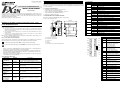
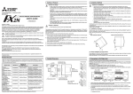
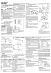
5.2 LED check Attach to DIN Rail and Remove from DIN Rai 2. System configuration LED name The FX2N-10PG connects on the right side of a PLC main unit or extension unit/block (including special function blocks). FX2N-10PG connects by extension cable from the PLC main unit. (It is not possible to use the FX2N-10PG as a stand alone unit) FX2N-10PG is a special function block. A special function unit number 0-7 is automatically assigned from the PLC corresponding to its location on the communication lous. (Specified by FROM/TO instruction) The FX2N-10PG occupies eight points of I/O. State display Measures When the LED does not lit even if the power supply is supplied PLC. POWER OFF/ Blinking • Connect the extension cable between the PLC main unit and FX2N-10PG correctly. • Supply power to the PLC main unit correctly. • PLC service power supply capacity is exceeded. • Remove wiring from the terminal of the service power supply. Refer to the hardware manual of the connected main unit FX2N-2LC FX2N-10PG FX2N-32MR (X000 to X017) At START input ON. FX2N-32ER (X020 to X037) FX2N-10PG POWER ERROR FX2N-10PG L COM 24+ N X1 X2 X3 X4 X7 X10 IN START DOG X0 X1 fA fB X14 X16 X13 X15 FX2N-10PG L N IN POWER 0 1 2 3 4 5 6 7 0 1 2 3 4 5 6 7 0 1 2 3 4 5 6 7 0 1 2 3 4 5 6 7 START DOG X0 X1 fA fB X0 COM X2 X4 X6 X0 X2 X4 X6 X5 24+ X1 X3 X7 X1 X3 X5 X7 POWER 0 1 2 3 4 5 6 7 10 11 12 13 14 15 16 17 2) Direct mounting to back walls The FX2N-10PG can be mounted with M4 screws, using the direct mounting holes. An interval space between each unit of 1-2 mm is necessary. POWER RUN FX2N-32MR Y2 Y3 Y4 Y5 Y6 OUT 0 1 2 3 4 5 6 7 10 11 12 13 14 15 16 17 Y10 Y12 COM3 Y11 Y13 PROG.E FX2N-2LC CPU.E FX2N-32ER Y14 Y15 Y0 Y2 COM1 Y1 Y3 Y4 Y6 COM2 Y5 Y7 OUT Y0 Y2 COM3 Y1 Y3 Y4 Y6 COM4 Y5 Y7 OFF PGO FP RP CLR BATT.V Y1 POWER ERROR PGO FP RP CLR START ERROR Blinking Lit 24V FP OUT1 OUT2 (Y000 to Y017) Special block No. 0 Special block No. 1 (Y020 to Y037) Special block No.2 • Up to 8 FX2N-10PG can be connected to an FX2N/FX3U/FX3UC*1 series PLC. Up to 4 units can be connected to an FX2NC series PLC. • When connected to an FX2NC Series PLC, the FX2NC-CNV-IF is required. When connected to an FX3UC Series PLC, the FX2NC-CNV-IF or FX3UC-1PS-5V is required. • Optional cables FX0N-65EC or FX0N-30EC can be used to extend the distance from the host PLC. Only one extension cable can be used per system. RP OFF 4.1 General Specifications Applicable version FX2N series All versions (First release). FX2NC series All versions (First release). FX3U series All versions (First release). FX3UC series All versions (First release). OFF Items Specifications Items other than the following Same as general specification of the PLC main unit. (Refer to the PLC MANUAL) Dielectric with stand voltage AC 500V 1 minute (between each terminal and earth terminal) Items Input signal Power supply Caution 1) Do not lay signal cable near to high voltage power cable or house them in the same trunking duct. Effects of noise or surge induction may occur. Keep signal cables a safe distance of more than 100 mm (3.94") from these power cables. 2) Ground the shied wire or the shield of a shielded cable at one point on the PLC. Do not, however, ground at the same point as high voltage lines. 4) Replace the provided terminal cover before supplying power and operating the unit after installation or wiring work, in order to avoid electric shock. CLR • Internal control 5V DC consumption current 120mA from PLC main unit. Output signal FP, RP (Supply the power supply by the terminal of VIN. 5 to 24V DC): Have the current to 25mA or less. CLR: 5 to 24V DC have the consumption current to 20mA or less. Power from servo amplifier or external power supply Lit Check Wiring and Program of the PLC main unit when FX2N-10PG does not operate normally. FX2N-10PG will not operate normally if the FROM/TO instruction is executed when an abnormality occurs in the PLC main unit. Correspond according to the content when an abnormality occurs in the main unit (off POWER LED and blinking ERROR LED/Lit ERROR LED). (Refer to the HARDWARE MANUAL, PROGRAMMING MANUAL ΙΙ for PLC) ERROR LED is lit when an operation error occurs in the PLC main unit while turned off. (The instruction where the operation error occurs is not executed.) Check the ON/OFF status of M8067 with external programming equipment, and correct any errors. b) When removing the FX2N-10PG from the DIN rail, the hook for DIN rail is pulled (e), and the FX2N-10PG is removed (f). See Figure 3.1. *1 Uses DIN 46277 <35mm (1.38")> • Check the output wiring. An external power supply is necessary for the terminal CLR output (5 to 24V DC). DOG OFF PG0 OFF φA OFF φB OFF X0,X1 OFF • Check the input wiring. An external power supply is necessary for the terminal DOG. (24V DC). At PG0 input ON. • Check the input wiring. When NPN/PNP opening collector transistor is used, an external power supply is necessary for the terminal PG0. (5V DC). At φA, φB input ON. • Check the input wiring. When manual pulse generator of opening collector output type is used, an external power supply is necessary for the terminals φA, φB (5V DC). At X0,X1 input ON. • Check the input wiring. An external power supply is necessary for the terminal X0,X1(24V DC). 5. Diagnostics The FX2N-10PG can be DIN rail direct wall mounted. Align the upper side of the DIN rail mounting groove of the FX2N-10PG with a DIN rail *1 (c), and push it on the DIN rail(d). See Figure 3.1. • Home position return drive, the data set type Home position return, and the compulsion output of the CLR signal must be executed by programming the PLC main unit or check. Refer to the USER’S MANUAL for the performance specification and the I/O specification. 5.1 Preliminary Checks a) • Do not output the pulse when there are stop, forward limit, and reversal limit instruction. When a clear signal is not input with the servo amplifier. Specifications START,DOG,X0,X1: 24V DC +10% -10%. Consumption current 32mA or less. PG0: 3 to 5.5V DC. Consumption current 20mA or less. VIN: 5 to 24V DC. The consumption current when the power supply is used 5V DC is 100mA or less. The consumption current when the power supply is used 24V DC is 70mA or less. Power from external power supply. START,DOG,X0,X1 can connect service power supply of programmable controller main unit (24+ terminal) 3.1 Mounting 1) DIN rail mounting When output forward pulses and reverse pulses. At DOG input ON. Power Supply Specifications 3. Installation 3) Cut off all phases of power source before installing / removing or performing wiring work on the unit in order to avoid electric shock or damage of product. • Please contact a service representative. When Home position return is completed. General Specifications 4.2 Power Supply Specifications Series name • Error occurs in FX2N-10PG. Do measures corresponding to the content after checking the content of buffer memory (BFM#37). Refer to Specific manual name for details of BFM#37. • Dependent on PLC program, start each drive or check. 4. Specifications *1 Up to 7 units can be connected to the FX3UC-32MT-LT series PLC. 2.1 Applicable PLC OFF • Check the input wiring. An external power supply is necessary for the terminal START. (24V DC) This manual confers no industrial property rights or any rights of any other kind, nor does it confer any patent licenses. Mitsubishi Electric Corporation cannot be held responsible for any problems involving industrial property rights which may occur as a result of using the contents noted in this manual. Manual number : JY992D91901 Manual revision : C Date : SEPTEMBER 2007 HEAD OFFICE : TOKYO BUILDING, 2-7-3 MARUNOUCHI, CHIYODA-KU, TOKYO 100-8310, JAPAN HIMEJI WORKS : 840, CHIYODA CHO, HIMEJI, JAPAN JY992D91901C Effective SEP. 2007 Specifications are subject to change without notice