1
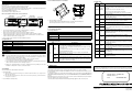
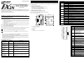
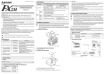
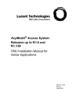
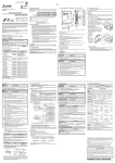
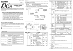
1.3 LED display 1. Introduction FX2N-10PG PULSE GENERATOR BLOCK INSTALLATION MANUAL JY992D91901C This manual contains text, diagrams and explanations which will guide the reader in the correct installation, safe use and operation of the FX2N-10PG PULSE GENERATOR BLOCK and should be read and understood before attempting to install or use the unit. Further information can be found in the manuals listed under further information. Specifications are subject to change without notice LED name The FX2N-10PG pulse generator block (Hereafter referred to as "FX2N-10PG" or "pulse generator block") outputs pulses of 1MHz or less. It is a special function block to drive amplifiers for servo motors or stepper motors. It is connected to an FX2N/FX2NC/FX3U/FX3UC series Programmable controller (Hereafter referred to as "PLC") and used. 1.1 Features of the FX2N-10PG 1) Positioning control with a stepper motor or servo motor. (1 FX2N-10PG can control 1 positioning axis.) All operators of the completed equipment should be trained to use that product in a safe and coordinated manner in compliance to established safety practices. DOG FX2N-10PG 1) Indicates that the identified danger WILL cause physical and property damage. START DOG X0 X1 fA fB PGO FP RP CLR 90(3.54) 80(3.15) PG0 φA c) f) d) 2-f4.5(0.18) e) φB X0,X1 74(2.91) • All examples and diagrams shown in this manual are intended only as an aid to understanding the text, not to guarantee operation. Mitsubishi Electric will accept no responsibility for actual use of the productbased on these illustrative examples. • Owing to the very great variety in possible application of this equipment, you must satisfy yourself as to its suitability for your specific application. OFF START input OFF. Lit START input ON. OFF Normal operation. Blinking Error has occurred. OFF Blinking OFF Blinking or lit OFF Lit CPU error Forward pulse or pulses not output. Forward pulse or pulses output. Reverse pulse or direction command not output. Reverse pulse or direction command output. CLR signal idle. CLR signal output (It completes Home position return). OFF DOG input OFF. Lit DOG input ON. OFF Zero point signal input OFF. Lit Zero point signal input ON. OFF A phase input of manual pulse generator OFF. Blinking A phase input of manual pulse generator ON. OFF B phase input of manual pulse generator OFF. Blinking B phase input of manual pulse generator ON. OFF Interrupt input OFF. Lit Interrupt input ON. Extension cable and connector b) Mounting hole 2-φ4.5(0.18inch) VIN+ c) Extension port FP+ FP- RP+ RP- d) I/O port e) DIN rail clip f) Under no circumstances will Mitsubishi Electric be liable responsible for any consequential damage that may arise as a result of the installation or use of this equipment. 5V DC is fed from the PLC main unit by way of the extension cable. 1.4 Array and allocation of pin Attachment groove for 35mm(1.38inch)wide DIN rail VIN- Terminal name Power supply input terminal for pulse output (5 to 24V DC) FP+ • Forward/reversal mode Forward pulse output terminal • Pulse/direction mode Pulse output terminal RP+ • Forward/reversal mode Reversal pulse output terminal • Pulse/direction mode Direction output terminal START PG0+ Zero point signal input terminal S/S S/S CLR+ Output terminal to clear collecting deflection counter pulse of servo amplifier X0 X1 PG0+ PG0- CLR+ CLR- φA+ φA- φB+ φB- DOG φA+ A phase input terminal of manual pulse generator φB+ B phase input terminal of manual pulse generator DOG input terminal Further Information Manual Lists Manual name Manual No. FX2N-10PG USER’S MANUAL JY992D93401 Describes specifications, wiring, installation, handling, etc. of FX2N-10PG. (Schedule in February, 2001.) DOG FX2N HARDWARE MANUAL JY992D66301 Describes contents related to hardware of FX2N series PLC such as specifications, wiring and installation. S/S Power supply input terminal (START,DOG,X0,X1) (24V DC) Pins (S/S) are short-circuited internally FX3U Series User’s Manual - Hardware Edition JY997D16501 Describes the specification, wiring and installation of FX3U series PLC. X0 Interruption input terminal FX2NC HARDWARE MANUAL JY992D76401 Description Content VIN+ 2) Indicates that the identified danger could POSSIBLY cause physical and property damage. • No 5V DC power from PLC main unit by way of the extension cable. Lit I/O port a) At various times through out this manual certain symbols will be used to highlight points of information which are intended to ensure the users personal safety and protect the integrity of equipment. CLR 87(3.43) 43(1.68) 4(0.16) POWER ERROR Note: The term ‘completed equipment’ refers to a third party constructed device which contains or uses the product associated with this manual. Note’s on the Symbols Used in this Manual RP Dimensions: mm (inches) MASS (Weight): Approx. 0.2kg (0.44 lbs) Accessory: Special block No. label Any engineer using the product associated with this manual, should be of a competent nature, trained and qualified to the local and national standards. These engineers should be fully aware of all aspects of safety with regards to automated equipment. c) FP Content of display OFF Lit 1.2 External Dimensions and Each Part Name This manual has been written to be used by trained and competent personnel. The definition of such a person or persons is as follows: Any commissioning or service engineer must be of a competent nature, trained and qualified to the local and national standards. ERROR 3) Pulses at up to 1MHz can be output. Guidelines for the Safety of the User and Protection of FX2N-10PG PULSE GENERATOR BLOCK b) START 2) Can be connected to an FX2N/FX2NC/FX3U/FX3UC series PLC. Data is read/written using FROM/TO instructions. a) b) a) POWER State Describes contents related to hardware of FX2NC series PLC such as specifications, wiring and installation. FX3UC Series User’s Manual - Hardware Edition JY997D28701 Describes the specification, wiring and installation of FX3UC series PLC. FX SERIES PROGRAMMING MANUAL ΙΙ JY992D88101 Describes instructions of FX1S/FX1N/FX2N/FX2NC series PLC FX3U/FX3UC Series Programming Manual - Basic & Applied Instruction Edition JY997D16601 This manual explains the installations of FX3U/FX3UC series PLC. VIN- Common terminal for VIN+ FP- Common terminal for FP+ RP- Common terminal for RP+ PG0- Common terminal for PG0 + CLR- Common terminal for CLR+ φA- Common terminal of A phase input for manual pulse generator φB- Common terminal of B phase input for manual pulse generator START X1 START input terminal Interruption input terminal 1.3 LED display 1. Introduction FX2N-10PG PULSE GENERATOR BLOCK INSTALLATION MANUAL JY992D91901C This manual contains text, diagrams and explanations which will guide the reader in the correct installation, safe use and operation of the FX2N-10PG PULSE GENERATOR BLOCK and should be read and understood before attempting to install or use the unit. Further information can be found in the manuals listed under further information. Specifications are subject to change without notice LED name The FX2N-10PG pulse generator block (Hereafter referred to as "FX2N-10PG" or "pulse generator block") outputs pulses of 1MHz or less. It is a special function block to drive amplifiers for servo motors or stepper motors. It is connected to an FX2N/FX2NC/FX3U/FX3UC series Programmable controller (Hereafter referred to as "PLC") and used. 1.1 Features of the FX2N-10PG 1) Positioning control with a stepper motor or servo motor. (1 FX2N-10PG can control 1 positioning axis.) All operators of the completed equipment should be trained to use that product in a safe and coordinated manner in compliance to established safety practices. DOG FX2N-10PG 1) Indicates that the identified danger WILL cause physical and property damage. START DOG X0 X1 fA fB PGO FP RP CLR 90(3.54) 80(3.15) PG0 φA c) f) d) 2-f4.5(0.18) e) φB X0,X1 74(2.91) • All examples and diagrams shown in this manual are intended only as an aid to understanding the text, not to guarantee operation. Mitsubishi Electric will accept no responsibility for actual use of the productbased on these illustrative examples. • Owing to the very great variety in possible application of this equipment, you must satisfy yourself as to its suitability for your specific application. OFF START input OFF. Lit START input ON. OFF Normal operation. Blinking Error has occurred. OFF Blinking OFF Blinking or lit OFF Lit CPU error Forward pulse or pulses not output. Forward pulse or pulses output. Reverse pulse or direction command not output. Reverse pulse or direction command output. CLR signal idle. CLR signal output (It completes Home position return). OFF DOG input OFF. Lit DOG input ON. OFF Zero point signal input OFF. Lit Zero point signal input ON. OFF A phase input of manual pulse generator OFF. Blinking A phase input of manual pulse generator ON. OFF B phase input of manual pulse generator OFF. Blinking B phase input of manual pulse generator ON. OFF Interrupt input OFF. Lit Interrupt input ON. Extension cable and connector b) Mounting hole 2-φ4.5(0.18inch) VIN+ c) Extension port FP+ FP- RP+ RP- d) I/O port e) DIN rail clip f) Under no circumstances will Mitsubishi Electric be liable responsible for any consequential damage that may arise as a result of the installation or use of this equipment. 5V DC is fed from the PLC main unit by way of the extension cable. 1.4 Array and allocation of pin Attachment groove for 35mm(1.38inch)wide DIN rail VIN- Terminal name Power supply input terminal for pulse output (5 to 24V DC) FP+ • Forward/reversal mode Forward pulse output terminal • Pulse/direction mode Pulse output terminal RP+ • Forward/reversal mode Reversal pulse output terminal • Pulse/direction mode Direction output terminal START PG0+ Zero point signal input terminal S/S S/S CLR+ Output terminal to clear collecting deflection counter pulse of servo amplifier X0 X1 PG0+ PG0- CLR+ CLR- φA+ φA- φB+ φB- DOG φA+ A phase input terminal of manual pulse generator φB+ B phase input terminal of manual pulse generator DOG input terminal Further Information Manual Lists Manual name Manual No. FX2N-10PG USER’S MANUAL JY992D93401 Describes specifications, wiring, installation, handling, etc. of FX2N-10PG. (Schedule in February, 2001.) DOG FX2N HARDWARE MANUAL JY992D66301 Describes contents related to hardware of FX2N series PLC such as specifications, wiring and installation. S/S Power supply input terminal (START,DOG,X0,X1) (24V DC) Pins (S/S) are short-circuited internally FX3U Series User’s Manual - Hardware Edition JY997D16501 Describes the specification, wiring and installation of FX3U series PLC. X0 Interruption input terminal FX2NC HARDWARE MANUAL JY992D76401 Description Content VIN+ 2) Indicates that the identified danger could POSSIBLY cause physical and property damage. • No 5V DC power from PLC main unit by way of the extension cable. Lit I/O port a) At various times through out this manual certain symbols will be used to highlight points of information which are intended to ensure the users personal safety and protect the integrity of equipment. CLR 87(3.43) 43(1.68) 4(0.16) POWER ERROR Note: The term ‘completed equipment’ refers to a third party constructed device which contains or uses the product associated with this manual. Note’s on the Symbols Used in this Manual RP Dimensions: mm (inches) MASS (Weight): Approx. 0.2kg (0.44 lbs) Accessory: Special block No. label Any engineer using the product associated with this manual, should be of a competent nature, trained and qualified to the local and national standards. These engineers should be fully aware of all aspects of safety with regards to automated equipment. c) FP Content of display OFF Lit 1.2 External Dimensions and Each Part Name This manual has been written to be used by trained and competent personnel. The definition of such a person or persons is as follows: Any commissioning or service engineer must be of a competent nature, trained and qualified to the local and national standards. ERROR 3) Pulses at up to 1MHz can be output. Guidelines for the Safety of the User and Protection of FX2N-10PG PULSE GENERATOR BLOCK b) START 2) Can be connected to an FX2N/FX2NC/FX3U/FX3UC series PLC. Data is read/written using FROM/TO instructions. a) b) a) POWER State Describes contents related to hardware of FX2NC series PLC such as specifications, wiring and installation. FX3UC Series User’s Manual - Hardware Edition JY997D28701 Describes the specification, wiring and installation of FX3UC series PLC. FX SERIES PROGRAMMING MANUAL ΙΙ JY992D88101 Describes instructions of FX1S/FX1N/FX2N/FX2NC series PLC FX3U/FX3UC Series Programming Manual - Basic & Applied Instruction Edition JY997D16601 This manual explains the installations of FX3U/FX3UC series PLC. VIN- Common terminal for VIN+ FP- Common terminal for FP+ RP- Common terminal for RP+ PG0- Common terminal for PG0 + CLR- Common terminal for CLR+ φA- Common terminal of A phase input for manual pulse generator φB- Common terminal of B phase input for manual pulse generator START X1 START input terminal Interruption input terminal 1.3 LED display 1. Introduction FX2N-10PG PULSE GENERATOR BLOCK INSTALLATION MANUAL JY992D91901C This manual contains text, diagrams and explanations which will guide the reader in the correct installation, safe use and operation of the FX2N-10PG PULSE GENERATOR BLOCK and should be read and understood before attempting to install or use the unit. Further information can be found in the manuals listed under further information. Specifications are subject to change without notice LED name The FX2N-10PG pulse generator block (Hereafter referred to as "FX2N-10PG" or "pulse generator block") outputs pulses of 1MHz or less. It is a special function block to drive amplifiers for servo motors or stepper motors. It is connected to an FX2N/FX2NC/FX3U/FX3UC series Programmable controller (Hereafter referred to as "PLC") and used. 1.1 Features of the FX2N-10PG 1) Positioning control with a stepper motor or servo motor. (1 FX2N-10PG can control 1 positioning axis.) All operators of the completed equipment should be trained to use that product in a safe and coordinated manner in compliance to established safety practices. DOG FX2N-10PG 1) Indicates that the identified danger WILL cause physical and property damage. START DOG X0 X1 fA fB PGO FP RP CLR 90(3.54) 80(3.15) PG0 φA c) f) d) 2-f4.5(0.18) e) φB X0,X1 74(2.91) • All examples and diagrams shown in this manual are intended only as an aid to understanding the text, not to guarantee operation. Mitsubishi Electric will accept no responsibility for actual use of the productbased on these illustrative examples. • Owing to the very great variety in possible application of this equipment, you must satisfy yourself as to its suitability for your specific application. OFF START input OFF. Lit START input ON. OFF Normal operation. Blinking Error has occurred. OFF Blinking OFF Blinking or lit OFF Lit CPU error Forward pulse or pulses not output. Forward pulse or pulses output. Reverse pulse or direction command not output. Reverse pulse or direction command output. CLR signal idle. CLR signal output (It completes Home position return). OFF DOG input OFF. Lit DOG input ON. OFF Zero point signal input OFF. Lit Zero point signal input ON. OFF A phase input of manual pulse generator OFF. Blinking A phase input of manual pulse generator ON. OFF B phase input of manual pulse generator OFF. Blinking B phase input of manual pulse generator ON. OFF Interrupt input OFF. Lit Interrupt input ON. Extension cable and connector b) Mounting hole 2-φ4.5(0.18inch) VIN+ c) Extension port FP+ FP- RP+ RP- d) I/O port e) DIN rail clip f) Under no circumstances will Mitsubishi Electric be liable responsible for any consequential damage that may arise as a result of the installation or use of this equipment. 5V DC is fed from the PLC main unit by way of the extension cable. 1.4 Array and allocation of pin Attachment groove for 35mm(1.38inch)wide DIN rail VIN- Terminal name Power supply input terminal for pulse output (5 to 24V DC) FP+ • Forward/reversal mode Forward pulse output terminal • Pulse/direction mode Pulse output terminal RP+ • Forward/reversal mode Reversal pulse output terminal • Pulse/direction mode Direction output terminal START PG0+ Zero point signal input terminal S/S S/S CLR+ Output terminal to clear collecting deflection counter pulse of servo amplifier X0 X1 PG0+ PG0- CLR+ CLR- φA+ φA- φB+ φB- DOG φA+ A phase input terminal of manual pulse generator φB+ B phase input terminal of manual pulse generator DOG input terminal Further Information Manual Lists Manual name Manual No. FX2N-10PG USER’S MANUAL JY992D93401 Describes specifications, wiring, installation, handling, etc. of FX2N-10PG. (Schedule in February, 2001.) DOG FX2N HARDWARE MANUAL JY992D66301 Describes contents related to hardware of FX2N series PLC such as specifications, wiring and installation. S/S Power supply input terminal (START,DOG,X0,X1) (24V DC) Pins (S/S) are short-circuited internally FX3U Series User’s Manual - Hardware Edition JY997D16501 Describes the specification, wiring and installation of FX3U series PLC. X0 Interruption input terminal FX2NC HARDWARE MANUAL JY992D76401 Description Content VIN+ 2) Indicates that the identified danger could POSSIBLY cause physical and property damage. • No 5V DC power from PLC main unit by way of the extension cable. Lit I/O port a) At various times through out this manual certain symbols will be used to highlight points of information which are intended to ensure the users personal safety and protect the integrity of equipment. CLR 87(3.43) 43(1.68) 4(0.16) POWER ERROR Note: The term ‘completed equipment’ refers to a third party constructed device which contains or uses the product associated with this manual. Note’s on the Symbols Used in this Manual RP Dimensions: mm (inches) MASS (Weight): Approx. 0.2kg (0.44 lbs) Accessory: Special block No. label Any engineer using the product associated with this manual, should be of a competent nature, trained and qualified to the local and national standards. These engineers should be fully aware of all aspects of safety with regards to automated equipment. c) FP Content of display OFF Lit 1.2 External Dimensions and Each Part Name This manual has been written to be used by trained and competent personnel. The definition of such a person or persons is as follows: Any commissioning or service engineer must be of a competent nature, trained and qualified to the local and national standards. ERROR 3) Pulses at up to 1MHz can be output. Guidelines for the Safety of the User and Protection of FX2N-10PG PULSE GENERATOR BLOCK b) START 2) Can be connected to an FX2N/FX2NC/FX3U/FX3UC series PLC. Data is read/written using FROM/TO instructions. a) b) a) POWER State Describes contents related to hardware of FX2NC series PLC such as specifications, wiring and installation. FX3UC Series User’s Manual - Hardware Edition JY997D28701 Describes the specification, wiring and installation of FX3UC series PLC. FX SERIES PROGRAMMING MANUAL ΙΙ JY992D88101 Describes instructions of FX1S/FX1N/FX2N/FX2NC series PLC FX3U/FX3UC Series Programming Manual - Basic & Applied Instruction Edition JY997D16601 This manual explains the installations of FX3U/FX3UC series PLC. VIN- Common terminal for VIN+ FP- Common terminal for FP+ RP- Common terminal for RP+ PG0- Common terminal for PG0 + CLR- Common terminal for CLR+ φA- Common terminal of A phase input for manual pulse generator φB- Common terminal of B phase input for manual pulse generator START X1 START input terminal Interruption input terminal 5.2 LED check Attach to DIN Rail and Remove from DIN Rai 2. System configuration LED name The FX2N-10PG connects on the right side of a PLC main unit or extension unit/block (including special function blocks). FX2N-10PG connects by extension cable from the PLC main unit. (It is not possible to use the FX2N-10PG as a stand alone unit) FX2N-10PG is a special function block. A special function unit number 0-7 is automatically assigned from the PLC corresponding to its location on the communication lous. (Specified by FROM/TO instruction) The FX2N-10PG occupies eight points of I/O. State display Measures When the LED does not lit even if the power supply is supplied PLC. POWER OFF/ Blinking • Connect the extension cable between the PLC main unit and FX2N-10PG correctly. • Supply power to the PLC main unit correctly. • PLC service power supply capacity is exceeded. • Remove wiring from the terminal of the service power supply. Refer to the hardware manual of the connected main unit FX2N-2LC FX2N-10PG FX2N-32MR (X000 to X017) At START input ON. FX2N-32ER (X020 to X037) FX2N-10PG POWER ERROR FX2N-10PG L COM 24+ N X1 X2 X3 X4 X7 X10 IN START DOG X0 X1 fA fB X14 X16 X13 X15 FX2N-10PG L N IN POWER 0 1 2 3 4 5 6 7 0 1 2 3 4 5 6 7 0 1 2 3 4 5 6 7 0 1 2 3 4 5 6 7 START DOG X0 X1 fA fB X0 COM X2 X4 X6 X0 X2 X4 X6 X5 24+ X1 X3 X7 X1 X3 X5 X7 POWER 0 1 2 3 4 5 6 7 10 11 12 13 14 15 16 17 2) Direct mounting to back walls The FX2N-10PG can be mounted with M4 screws, using the direct mounting holes. An interval space between each unit of 1-2 mm is necessary. POWER RUN FX2N-32MR Y2 Y3 Y4 Y5 Y6 OUT 0 1 2 3 4 5 6 7 10 11 12 13 14 15 16 17 Y10 Y12 COM3 Y11 Y13 PROG.E FX2N-2LC CPU.E FX2N-32ER Y14 Y15 Y0 Y2 COM1 Y1 Y3 Y4 Y6 COM2 Y5 Y7 OUT Y0 Y2 COM3 Y1 Y3 Y4 Y6 COM4 Y5 Y7 OFF PGO FP RP CLR BATT.V Y1 POWER ERROR PGO FP RP CLR START ERROR Blinking Lit 24V FP OUT1 OUT2 (Y000 to Y017) Special block No. 0 Special block No. 1 (Y020 to Y037) Special block No.2 • Up to 8 FX2N-10PG can be connected to an FX2N/FX3U/FX3UC*1 series PLC. Up to 4 units can be connected to an FX2NC series PLC. • When connected to an FX2NC Series PLC, the FX2NC-CNV-IF is required. When connected to an FX3UC Series PLC, the FX2NC-CNV-IF or FX3UC-1PS-5V is required. • Optional cables FX0N-65EC or FX0N-30EC can be used to extend the distance from the host PLC. Only one extension cable can be used per system. RP OFF 4.1 General Specifications Applicable version FX2N series All versions (First release). FX2NC series All versions (First release). FX3U series All versions (First release). FX3UC series All versions (First release). OFF Items Specifications Items other than the following Same as general specification of the PLC main unit. (Refer to the PLC MANUAL) Dielectric with stand voltage AC 500V 1 minute (between each terminal and earth terminal) Items Input signal Power supply Caution 1) Do not lay signal cable near to high voltage power cable or house them in the same trunking duct. Effects of noise or surge induction may occur. Keep signal cables a safe distance of more than 100 mm (3.94") from these power cables. 2) Ground the shied wire or the shield of a shielded cable at one point on the PLC. Do not, however, ground at the same point as high voltage lines. 4) Replace the provided terminal cover before supplying power and operating the unit after installation or wiring work, in order to avoid electric shock. CLR • Internal control 5V DC consumption current 120mA from PLC main unit. Output signal FP, RP (Supply the power supply by the terminal of VIN. 5 to 24V DC): Have the current to 25mA or less. CLR: 5 to 24V DC have the consumption current to 20mA or less. Power from servo amplifier or external power supply Lit Check Wiring and Program of the PLC main unit when FX2N-10PG does not operate normally. FX2N-10PG will not operate normally if the FROM/TO instruction is executed when an abnormality occurs in the PLC main unit. Correspond according to the content when an abnormality occurs in the main unit (off POWER LED and blinking ERROR LED/Lit ERROR LED). (Refer to the HARDWARE MANUAL, PROGRAMMING MANUAL ΙΙ for PLC) ERROR LED is lit when an operation error occurs in the PLC main unit while turned off. (The instruction where the operation error occurs is not executed.) Check the ON/OFF status of M8067 with external programming equipment, and correct any errors. b) When removing the FX2N-10PG from the DIN rail, the hook for DIN rail is pulled (e), and the FX2N-10PG is removed (f). See Figure 3.1. *1 Uses DIN 46277 <35mm (1.38")> • Check the output wiring. An external power supply is necessary for the terminal CLR output (5 to 24V DC). DOG OFF PG0 OFF φA OFF φB OFF X0,X1 OFF • Check the input wiring. An external power supply is necessary for the terminal DOG. (24V DC). At PG0 input ON. • Check the input wiring. When NPN/PNP opening collector transistor is used, an external power supply is necessary for the terminal PG0. (5V DC). At φA, φB input ON. • Check the input wiring. When manual pulse generator of opening collector output type is used, an external power supply is necessary for the terminals φA, φB (5V DC). At X0,X1 input ON. • Check the input wiring. An external power supply is necessary for the terminal X0,X1(24V DC). 5. Diagnostics The FX2N-10PG can be DIN rail direct wall mounted. Align the upper side of the DIN rail mounting groove of the FX2N-10PG with a DIN rail *1 (c), and push it on the DIN rail(d). See Figure 3.1. • Home position return drive, the data set type Home position return, and the compulsion output of the CLR signal must be executed by programming the PLC main unit or check. Refer to the USER’S MANUAL for the performance specification and the I/O specification. 5.1 Preliminary Checks a) • Do not output the pulse when there are stop, forward limit, and reversal limit instruction. When a clear signal is not input with the servo amplifier. Specifications START,DOG,X0,X1: 24V DC +10% -10%. Consumption current 32mA or less. PG0: 3 to 5.5V DC. Consumption current 20mA or less. VIN: 5 to 24V DC. The consumption current when the power supply is used 5V DC is 100mA or less. The consumption current when the power supply is used 24V DC is 70mA or less. Power from external power supply. START,DOG,X0,X1 can connect service power supply of programmable controller main unit (24+ terminal) 3.1 Mounting 1) DIN rail mounting When output forward pulses and reverse pulses. At DOG input ON. Power Supply Specifications 3. Installation 3) Cut off all phases of power source before installing / removing or performing wiring work on the unit in order to avoid electric shock or damage of product. • Please contact a service representative. When Home position return is completed. General Specifications 4.2 Power Supply Specifications Series name • Error occurs in FX2N-10PG. Do measures corresponding to the content after checking the content of buffer memory (BFM#37). Refer to Specific manual name for details of BFM#37. • Dependent on PLC program, start each drive or check. 4. Specifications *1 Up to 7 units can be connected to the FX3UC-32MT-LT series PLC. 2.1 Applicable PLC OFF • Check the input wiring. An external power supply is necessary for the terminal START. (24V DC) This manual confers no industrial property rights or any rights of any other kind, nor does it confer any patent licenses. Mitsubishi Electric Corporation cannot be held responsible for any problems involving industrial property rights which may occur as a result of using the contents noted in this manual. Manual number : JY992D91901 Manual revision : C Date : SEPTEMBER 2007 HEAD OFFICE : TOKYO BUILDING, 2-7-3 MARUNOUCHI, CHIYODA-KU, TOKYO 100-8310, JAPAN HIMEJI WORKS : 840, CHIYODA CHO, HIMEJI, JAPAN JY992D91901C Effective SEP. 2007 Specifications are subject to change without notice 5.2 LED check Attach to DIN Rail and Remove from DIN Rai 2. System configuration LED name The FX2N-10PG connects on the right side of a PLC main unit or extension unit/block (including special function blocks). FX2N-10PG connects by extension cable from the PLC main unit. (It is not possible to use the FX2N-10PG as a stand alone unit) FX2N-10PG is a special function block. A special function unit number 0-7 is automatically assigned from the PLC corresponding to its location on the communication lous. (Specified by FROM/TO instruction) The FX2N-10PG occupies eight points of I/O. State display Measures When the LED does not lit even if the power supply is supplied PLC. POWER OFF/ Blinking • Connect the extension cable between the PLC main unit and FX2N-10PG correctly. • Supply power to the PLC main unit correctly. • PLC service power supply capacity is exceeded. • Remove wiring from the terminal of the service power supply. Refer to the hardware manual of the connected main unit FX2N-2LC FX2N-10PG FX2N-32MR (X000 to X017) At START input ON. FX2N-32ER (X020 to X037) FX2N-10PG POWER ERROR FX2N-10PG L COM 24+ N X1 X2 X3 X4 X7 X10 IN START DOG X0 X1 fA fB X14 X16 X13 X15 FX2N-10PG L N IN POWER 0 1 2 3 4 5 6 7 0 1 2 3 4 5 6 7 0 1 2 3 4 5 6 7 0 1 2 3 4 5 6 7 START DOG X0 X1 fA fB X0 COM X2 X4 X6 X0 X2 X4 X6 X5 24+ X1 X3 X7 X1 X3 X5 X7 POWER 0 1 2 3 4 5 6 7 10 11 12 13 14 15 16 17 2) Direct mounting to back walls The FX2N-10PG can be mounted with M4 screws, using the direct mounting holes. An interval space between each unit of 1-2 mm is necessary. POWER RUN FX2N-32MR Y2 Y3 Y4 Y5 Y6 OUT 0 1 2 3 4 5 6 7 10 11 12 13 14 15 16 17 Y10 Y12 COM3 Y11 Y13 PROG.E FX2N-2LC CPU.E FX2N-32ER Y14 Y15 Y0 Y2 COM1 Y1 Y3 Y4 Y6 COM2 Y5 Y7 OUT Y0 Y2 COM3 Y1 Y3 Y4 Y6 COM4 Y5 Y7 OFF PGO FP RP CLR BATT.V Y1 POWER ERROR PGO FP RP CLR START ERROR Blinking Lit 24V FP OUT1 OUT2 (Y000 to Y017) Special block No. 0 Special block No. 1 (Y020 to Y037) Special block No.2 • Up to 8 FX2N-10PG can be connected to an FX2N/FX3U/FX3UC*1 series PLC. Up to 4 units can be connected to an FX2NC series PLC. • When connected to an FX2NC Series PLC, the FX2NC-CNV-IF is required. When connected to an FX3UC Series PLC, the FX2NC-CNV-IF or FX3UC-1PS-5V is required. • Optional cables FX0N-65EC or FX0N-30EC can be used to extend the distance from the host PLC. Only one extension cable can be used per system. RP OFF 4.1 General Specifications Applicable version FX2N series All versions (First release). FX2NC series All versions (First release). FX3U series All versions (First release). FX3UC series All versions (First release). OFF Items Specifications Items other than the following Same as general specification of the PLC main unit. (Refer to the PLC MANUAL) Dielectric with stand voltage AC 500V 1 minute (between each terminal and earth terminal) Items Input signal Power supply Caution 1) Do not lay signal cable near to high voltage power cable or house them in the same trunking duct. Effects of noise or surge induction may occur. Keep signal cables a safe distance of more than 100 mm (3.94") from these power cables. 2) Ground the shied wire or the shield of a shielded cable at one point on the PLC. Do not, however, ground at the same point as high voltage lines. 4) Replace the provided terminal cover before supplying power and operating the unit after installation or wiring work, in order to avoid electric shock. CLR • Internal control 5V DC consumption current 120mA from PLC main unit. Output signal FP, RP (Supply the power supply by the terminal of VIN. 5 to 24V DC): Have the current to 25mA or less. CLR: 5 to 24V DC have the consumption current to 20mA or less. Power from servo amplifier or external power supply Lit Check Wiring and Program of the PLC main unit when FX2N-10PG does not operate normally. FX2N-10PG will not operate normally if the FROM/TO instruction is executed when an abnormality occurs in the PLC main unit. Correspond according to the content when an abnormality occurs in the main unit (off POWER LED and blinking ERROR LED/Lit ERROR LED). (Refer to the HARDWARE MANUAL, PROGRAMMING MANUAL ΙΙ for PLC) ERROR LED is lit when an operation error occurs in the PLC main unit while turned off. (The instruction where the operation error occurs is not executed.) Check the ON/OFF status of M8067 with external programming equipment, and correct any errors. b) When removing the FX2N-10PG from the DIN rail, the hook for DIN rail is pulled (e), and the FX2N-10PG is removed (f). See Figure 3.1. *1 Uses DIN 46277 <35mm (1.38")> • Check the output wiring. An external power supply is necessary for the terminal CLR output (5 to 24V DC). DOG OFF PG0 OFF φA OFF φB OFF X0,X1 OFF • Check the input wiring. An external power supply is necessary for the terminal DOG. (24V DC). At PG0 input ON. • Check the input wiring. When NPN/PNP opening collector transistor is used, an external power supply is necessary for the terminal PG0. (5V DC). At φA, φB input ON. • Check the input wiring. When manual pulse generator of opening collector output type is used, an external power supply is necessary for the terminals φA, φB (5V DC). At X0,X1 input ON. • Check the input wiring. An external power supply is necessary for the terminal X0,X1(24V DC). 5. Diagnostics The FX2N-10PG can be DIN rail direct wall mounted. Align the upper side of the DIN rail mounting groove of the FX2N-10PG with a DIN rail *1 (c), and push it on the DIN rail(d). See Figure 3.1. • Home position return drive, the data set type Home position return, and the compulsion output of the CLR signal must be executed by programming the PLC main unit or check. Refer to the USER’S MANUAL for the performance specification and the I/O specification. 5.1 Preliminary Checks a) • Do not output the pulse when there are stop, forward limit, and reversal limit instruction. When a clear signal is not input with the servo amplifier. Specifications START,DOG,X0,X1: 24V DC +10% -10%. Consumption current 32mA or less. PG0: 3 to 5.5V DC. Consumption current 20mA or less. VIN: 5 to 24V DC. The consumption current when the power supply is used 5V DC is 100mA or less. The consumption current when the power supply is used 24V DC is 70mA or less. Power from external power supply. START,DOG,X0,X1 can connect service power supply of programmable controller main unit (24+ terminal) 3.1 Mounting 1) DIN rail mounting When output forward pulses and reverse pulses. At DOG input ON. Power Supply Specifications 3. Installation 3) Cut off all phases of power source before installing / removing or performing wiring work on the unit in order to avoid electric shock or damage of product. • Please contact a service representative. When Home position return is completed. General Specifications 4.2 Power Supply Specifications Series name • Error occurs in FX2N-10PG. Do measures corresponding to the content after checking the content of buffer memory (BFM#37). Refer to Specific manual name for details of BFM#37. • Dependent on PLC program, start each drive or check. 4. Specifications *1 Up to 7 units can be connected to the FX3UC-32MT-LT series PLC. 2.1 Applicable PLC OFF • Check the input wiring. An external power supply is necessary for the terminal START. (24V DC) This manual confers no industrial property rights or any rights of any other kind, nor does it confer any patent licenses. Mitsubishi Electric Corporation cannot be held responsible for any problems involving industrial property rights which may occur as a result of using the contents noted in this manual. Manual number : JY992D91901 Manual revision : C Date : SEPTEMBER 2007 HEAD OFFICE : TOKYO BUILDING, 2-7-3 MARUNOUCHI, CHIYODA-KU, TOKYO 100-8310, JAPAN HIMEJI WORKS : 840, CHIYODA CHO, HIMEJI, JAPAN JY992D91901C Effective SEP. 2007 Specifications are subject to change without notice 5.2 LED check Attach to DIN Rail and Remove from DIN Rai 2. System configuration LED name The FX2N-10PG connects on the right side of a PLC main unit or extension unit/block (including special function blocks). FX2N-10PG connects by extension cable from the PLC main unit. (It is not possible to use the FX2N-10PG as a stand alone unit) FX2N-10PG is a special function block. A special function unit number 0-7 is automatically assigned from the PLC corresponding to its location on the communication lous. (Specified by FROM/TO instruction) The FX2N-10PG occupies eight points of I/O. State display Measures When the LED does not lit even if the power supply is supplied PLC. POWER OFF/ Blinking • Connect the extension cable between the PLC main unit and FX2N-10PG correctly. • Supply power to the PLC main unit correctly. • PLC service power supply capacity is exceeded. • Remove wiring from the terminal of the service power supply. Refer to the hardware manual of the connected main unit FX2N-2LC FX2N-10PG FX2N-32MR (X000 to X017) At START input ON. FX2N-32ER (X020 to X037) FX2N-10PG POWER ERROR FX2N-10PG L COM 24+ N X1 X2 X3 X4 X7 X10 IN START DOG X0 X1 fA fB X14 X16 X13 X15 FX2N-10PG L N IN POWER 0 1 2 3 4 5 6 7 0 1 2 3 4 5 6 7 0 1 2 3 4 5 6 7 0 1 2 3 4 5 6 7 START DOG X0 X1 fA fB X0 COM X2 X4 X6 X0 X2 X4 X6 X5 24+ X1 X3 X7 X1 X3 X5 X7 POWER 0 1 2 3 4 5 6 7 10 11 12 13 14 15 16 17 2) Direct mounting to back walls The FX2N-10PG can be mounted with M4 screws, using the direct mounting holes. An interval space between each unit of 1-2 mm is necessary. POWER RUN FX2N-32MR Y2 Y3 Y4 Y5 Y6 OUT 0 1 2 3 4 5 6 7 10 11 12 13 14 15 16 17 Y10 Y12 COM3 Y11 Y13 PROG.E FX2N-2LC CPU.E FX2N-32ER Y14 Y15 Y0 Y2 COM1 Y1 Y3 Y4 Y6 COM2 Y5 Y7 OUT Y0 Y2 COM3 Y1 Y3 Y4 Y6 COM4 Y5 Y7 OFF PGO FP RP CLR BATT.V Y1 POWER ERROR PGO FP RP CLR START ERROR Blinking Lit 24V FP OUT1 OUT2 (Y000 to Y017) Special block No. 0 Special block No. 1 (Y020 to Y037) Special block No.2 • Up to 8 FX2N-10PG can be connected to an FX2N/FX3U/FX3UC*1 series PLC. Up to 4 units can be connected to an FX2NC series PLC. • When connected to an FX2NC Series PLC, the FX2NC-CNV-IF is required. When connected to an FX3UC Series PLC, the FX2NC-CNV-IF or FX3UC-1PS-5V is required. • Optional cables FX0N-65EC or FX0N-30EC can be used to extend the distance from the host PLC. Only one extension cable can be used per system. RP OFF 4.1 General Specifications Applicable version FX2N series All versions (First release). FX2NC series All versions (First release). FX3U series All versions (First release). FX3UC series All versions (First release). OFF Items Specifications Items other than the following Same as general specification of the PLC main unit. (Refer to the PLC MANUAL) Dielectric with stand voltage AC 500V 1 minute (between each terminal and earth terminal) Items Input signal Power supply Caution 1) Do not lay signal cable near to high voltage power cable or house them in the same trunking duct. Effects of noise or surge induction may occur. Keep signal cables a safe distance of more than 100 mm (3.94") from these power cables. 2) Ground the shied wire or the shield of a shielded cable at one point on the PLC. Do not, however, ground at the same point as high voltage lines. 4) Replace the provided terminal cover before supplying power and operating the unit after installation or wiring work, in order to avoid electric shock. CLR • Internal control 5V DC consumption current 120mA from PLC main unit. Output signal FP, RP (Supply the power supply by the terminal of VIN. 5 to 24V DC): Have the current to 25mA or less. CLR: 5 to 24V DC have the consumption current to 20mA or less. Power from servo amplifier or external power supply Lit Check Wiring and Program of the PLC main unit when FX2N-10PG does not operate normally. FX2N-10PG will not operate normally if the FROM/TO instruction is executed when an abnormality occurs in the PLC main unit. Correspond according to the content when an abnormality occurs in the main unit (off POWER LED and blinking ERROR LED/Lit ERROR LED). (Refer to the HARDWARE MANUAL, PROGRAMMING MANUAL ΙΙ for PLC) ERROR LED is lit when an operation error occurs in the PLC main unit while turned off. (The instruction where the operation error occurs is not executed.) Check the ON/OFF status of M8067 with external programming equipment, and correct any errors. b) When removing the FX2N-10PG from the DIN rail, the hook for DIN rail is pulled (e), and the FX2N-10PG is removed (f). See Figure 3.1. *1 Uses DIN 46277 <35mm (1.38")> • Check the output wiring. An external power supply is necessary for the terminal CLR output (5 to 24V DC). DOG OFF PG0 OFF φA OFF φB OFF X0,X1 OFF • Check the input wiring. An external power supply is necessary for the terminal DOG. (24V DC). At PG0 input ON. • Check the input wiring. When NPN/PNP opening collector transistor is used, an external power supply is necessary for the terminal PG0. (5V DC). At φA, φB input ON. • Check the input wiring. When manual pulse generator of opening collector output type is used, an external power supply is necessary for the terminals φA, φB (5V DC). At X0,X1 input ON. • Check the input wiring. An external power supply is necessary for the terminal X0,X1(24V DC). 5. Diagnostics The FX2N-10PG can be DIN rail direct wall mounted. Align the upper side of the DIN rail mounting groove of the FX2N-10PG with a DIN rail *1 (c), and push it on the DIN rail(d). See Figure 3.1. • Home position return drive, the data set type Home position return, and the compulsion output of the CLR signal must be executed by programming the PLC main unit or check. Refer to the USER’S MANUAL for the performance specification and the I/O specification. 5.1 Preliminary Checks a) • Do not output the pulse when there are stop, forward limit, and reversal limit instruction. When a clear signal is not input with the servo amplifier. Specifications START,DOG,X0,X1: 24V DC +10% -10%. Consumption current 32mA or less. PG0: 3 to 5.5V DC. Consumption current 20mA or less. VIN: 5 to 24V DC. The consumption current when the power supply is used 5V DC is 100mA or less. The consumption current when the power supply is used 24V DC is 70mA or less. Power from external power supply. START,DOG,X0,X1 can connect service power supply of programmable controller main unit (24+ terminal) 3.1 Mounting 1) DIN rail mounting When output forward pulses and reverse pulses. At DOG input ON. Power Supply Specifications 3. Installation 3) Cut off all phases of power source before installing / removing or performing wiring work on the unit in order to avoid electric shock or damage of product. • Please contact a service representative. When Home position return is completed. General Specifications 4.2 Power Supply Specifications Series name • Error occurs in FX2N-10PG. Do measures corresponding to the content after checking the content of buffer memory (BFM#37). Refer to Specific manual name for details of BFM#37. • Dependent on PLC program, start each drive or check. 4. Specifications *1 Up to 7 units can be connected to the FX3UC-32MT-LT series PLC. 2.1 Applicable PLC OFF • Check the input wiring. An external power supply is necessary for the terminal START. (24V DC) This manual confers no industrial property rights or any rights of any other kind, nor does it confer any patent licenses. Mitsubishi Electric Corporation cannot be held responsible for any problems involving industrial property rights which may occur as a result of using the contents noted in this manual. Manual number : JY992D91901 Manual revision : C Date : SEPTEMBER 2007 HEAD OFFICE : TOKYO BUILDING, 2-7-3 MARUNOUCHI, CHIYODA-KU, TOKYO 100-8310, JAPAN HIMEJI WORKS : 840, CHIYODA CHO, HIMEJI, JAPAN JY992D91901C Effective SEP. 2007 Specifications are subject to change without notice 1.3 LED display 1. Introduction FX2N-10PG PULSE GENERATOR BLOCK INSTALLATION MANUAL JY992D91901C This manual contains text, diagrams and explanations which will guide the reader in the correct installation, safe use and operation of the FX2N-10PG PULSE GENERATOR BLOCK and should be read and understood before attempting to install or use the unit. Further information can be found in the manuals listed under further information. Specifications are subject to change without notice LED name The FX2N-10PG pulse generator block (Hereafter referred to as "FX2N-10PG" or "pulse generator block") outputs pulses of 1MHz or less. It is a special function block to drive amplifiers for servo motors or stepper motors. It is connected to an FX2N/FX2NC/FX3U/FX3UC series Programmable controller (Hereafter referred to as "PLC") and used. 1.1 Features of the FX2N-10PG 1) Positioning control with a stepper motor or servo motor. (1 FX2N-10PG can control 1 positioning axis.) All operators of the completed equipment should be trained to use that product in a safe and coordinated manner in compliance to established safety practices. DOG FX2N-10PG 1) Indicates that the identified danger WILL cause physical and property damage. START DOG X0 X1 fA fB PGO FP RP CLR 90(3.54) 80(3.15) PG0 φA c) f) d) 2-f4.5(0.18) e) φB X0,X1 74(2.91) • All examples and diagrams shown in this manual are intended only as an aid to understanding the text, not to guarantee operation. Mitsubishi Electric will accept no responsibility for actual use of the productbased on these illustrative examples. • Owing to the very great variety in possible application of this equipment, you must satisfy yourself as to its suitability for your specific application. OFF START input OFF. Lit START input ON. OFF Normal operation. Blinking Error has occurred. OFF Blinking OFF Blinking or lit OFF Lit CPU error Forward pulse or pulses not output. Forward pulse or pulses output. Reverse pulse or direction command not output. Reverse pulse or direction command output. CLR signal idle. CLR signal output (It completes Home position return). OFF DOG input OFF. Lit DOG input ON. OFF Zero point signal input OFF. Lit Zero point signal input ON. OFF A phase input of manual pulse generator OFF. Blinking A phase input of manual pulse generator ON. OFF B phase input of manual pulse generator OFF. Blinking B phase input of manual pulse generator ON. OFF Interrupt input OFF. Lit Interrupt input ON. Extension cable and connector b) Mounting hole 2-φ4.5(0.18inch) VIN+ c) Extension port FP+ FP- RP+ RP- d) I/O port e) DIN rail clip f) Under no circumstances will Mitsubishi Electric be liable responsible for any consequential damage that may arise as a result of the installation or use of this equipment. 5V DC is fed from the PLC main unit by way of the extension cable. 1.4 Array and allocation of pin Attachment groove for 35mm(1.38inch)wide DIN rail VIN- Terminal name Power supply input terminal for pulse output (5 to 24V DC) FP+ • Forward/reversal mode Forward pulse output terminal • Pulse/direction mode Pulse output terminal RP+ • Forward/reversal mode Reversal pulse output terminal • Pulse/direction mode Direction output terminal START PG0+ Zero point signal input terminal S/S S/S CLR+ Output terminal to clear collecting deflection counter pulse of servo amplifier X0 X1 PG0+ PG0- CLR+ CLR- φA+ φA- φB+ φB- DOG φA+ A phase input terminal of manual pulse generator φB+ B phase input terminal of manual pulse generator DOG input terminal Further Information Manual Lists Manual name Manual No. FX2N-10PG USER’S MANUAL JY992D93401 Describes specifications, wiring, installation, handling, etc. of FX2N-10PG. (Schedule in February, 2001.) DOG FX2N HARDWARE MANUAL JY992D66301 Describes contents related to hardware of FX2N series PLC such as specifications, wiring and installation. S/S Power supply input terminal (START,DOG,X0,X1) (24V DC) Pins (S/S) are short-circuited internally FX3U Series User’s Manual - Hardware Edition JY997D16501 Describes the specification, wiring and installation of FX3U series PLC. X0 Interruption input terminal FX2NC HARDWARE MANUAL JY992D76401 Description Content VIN+ 2) Indicates that the identified danger could POSSIBLY cause physical and property damage. • No 5V DC power from PLC main unit by way of the extension cable. Lit I/O port a) At various times through out this manual certain symbols will be used to highlight points of information which are intended to ensure the users personal safety and protect the integrity of equipment. CLR 87(3.43) 43(1.68) 4(0.16) POWER ERROR Note: The term ‘completed equipment’ refers to a third party constructed device which contains or uses the product associated with this manual. Note’s on the Symbols Used in this Manual RP Dimensions: mm (inches) MASS (Weight): Approx. 0.2kg (0.44 lbs) Accessory: Special block No. label Any engineer using the product associated with this manual, should be of a competent nature, trained and qualified to the local and national standards. These engineers should be fully aware of all aspects of safety with regards to automated equipment. c) FP Content of display OFF Lit 1.2 External Dimensions and Each Part Name This manual has been written to be used by trained and competent personnel. The definition of such a person or persons is as follows: Any commissioning or service engineer must be of a competent nature, trained and qualified to the local and national standards. ERROR 3) Pulses at up to 1MHz can be output. Guidelines for the Safety of the User and Protection of FX2N-10PG PULSE GENERATOR BLOCK b) START 2) Can be connected to an FX2N/FX2NC/FX3U/FX3UC series PLC. Data is read/written using FROM/TO instructions. a) b) a) POWER State Describes contents related to hardware of FX2NC series PLC such as specifications, wiring and installation. FX3UC Series User’s Manual - Hardware Edition JY997D28701 Describes the specification, wiring and installation of FX3UC series PLC. FX SERIES PROGRAMMING MANUAL ΙΙ JY992D88101 Describes instructions of FX1S/FX1N/FX2N/FX2NC series PLC FX3U/FX3UC Series Programming Manual - Basic & Applied Instruction Edition JY997D16601 This manual explains the installations of FX3U/FX3UC series PLC. VIN- Common terminal for VIN+ FP- Common terminal for FP+ RP- Common terminal for RP+ PG0- Common terminal for PG0 + CLR- Common terminal for CLR+ φA- Common terminal of A phase input for manual pulse generator φB- Common terminal of B phase input for manual pulse generator START X1 START input terminal Interruption input terminal 5.2 LED check Attach to DIN Rail and Remove from DIN Rai 2. System configuration LED name The FX2N-10PG connects on the right side of a PLC main unit or extension unit/block (including special function blocks). FX2N-10PG connects by extension cable from the PLC main unit. (It is not possible to use the FX2N-10PG as a stand alone unit) FX2N-10PG is a special function block. A special function unit number 0-7 is automatically assigned from the PLC corresponding to its location on the communication lous. (Specified by FROM/TO instruction) The FX2N-10PG occupies eight points of I/O. State display Measures When the LED does not lit even if the power supply is supplied PLC. POWER OFF/ Blinking • Connect the extension cable between the PLC main unit and FX2N-10PG correctly. • Supply power to the PLC main unit correctly. • PLC service power supply capacity is exceeded. • Remove wiring from the terminal of the service power supply. Refer to the hardware manual of the connected main unit FX2N-2LC FX2N-10PG FX2N-32MR (X000 to X017) At START input ON. FX2N-32ER (X020 to X037) FX2N-10PG POWER ERROR FX2N-10PG L COM 24+ N X1 X2 X3 X4 X7 X10 IN START DOG X0 X1 fA fB X14 X16 X13 X15 FX2N-10PG L N IN POWER 0 1 2 3 4 5 6 7 0 1 2 3 4 5 6 7 0 1 2 3 4 5 6 7 0 1 2 3 4 5 6 7 START DOG X0 X1 fA fB X0 COM X2 X4 X6 X0 X2 X4 X6 X5 24+ X1 X3 X7 X1 X3 X5 X7 POWER 0 1 2 3 4 5 6 7 10 11 12 13 14 15 16 17 2) Direct mounting to back walls The FX2N-10PG can be mounted with M4 screws, using the direct mounting holes. An interval space between each unit of 1-2 mm is necessary. POWER RUN FX2N-32MR Y2 Y3 Y4 Y5 Y6 OUT 0 1 2 3 4 5 6 7 10 11 12 13 14 15 16 17 Y10 Y12 COM3 Y11 Y13 PROG.E FX2N-2LC CPU.E FX2N-32ER Y14 Y15 Y0 Y2 COM1 Y1 Y3 Y4 Y6 COM2 Y5 Y7 OUT Y0 Y2 COM3 Y1 Y3 Y4 Y6 COM4 Y5 Y7 OFF PGO FP RP CLR BATT.V Y1 POWER ERROR PGO FP RP CLR START ERROR Blinking Lit 24V FP OUT1 OUT2 (Y000 to Y017) Special block No. 0 Special block No. 1 (Y020 to Y037) Special block No.2 • Up to 8 FX2N-10PG can be connected to an FX2N/FX3U/FX3UC*1 series PLC. Up to 4 units can be connected to an FX2NC series PLC. • When connected to an FX2NC Series PLC, the FX2NC-CNV-IF is required. When connected to an FX3UC Series PLC, the FX2NC-CNV-IF or FX3UC-1PS-5V is required. • Optional cables FX0N-65EC or FX0N-30EC can be used to extend the distance from the host PLC. Only one extension cable can be used per system. RP OFF 4.1 General Specifications Applicable version FX2N series All versions (First release). FX2NC series All versions (First release). FX3U series All versions (First release). FX3UC series All versions (First release). OFF Items Specifications Items other than the following Same as general specification of the PLC main unit. (Refer to the PLC MANUAL) Dielectric with stand voltage AC 500V 1 minute (between each terminal and earth terminal) Items Input signal Power supply Caution 1) Do not lay signal cable near to high voltage power cable or house them in the same trunking duct. Effects of noise or surge induction may occur. Keep signal cables a safe distance of more than 100 mm (3.94") from these power cables. 2) Ground the shied wire or the shield of a shielded cable at one point on the PLC. Do not, however, ground at the same point as high voltage lines. 4) Replace the provided terminal cover before supplying power and operating the unit after installation or wiring work, in order to avoid electric shock. CLR • Internal control 5V DC consumption current 120mA from PLC main unit. Output signal FP, RP (Supply the power supply by the terminal of VIN. 5 to 24V DC): Have the current to 25mA or less. CLR: 5 to 24V DC have the consumption current to 20mA or less. Power from servo amplifier or external power supply Lit Check Wiring and Program of the PLC main unit when FX2N-10PG does not operate normally. FX2N-10PG will not operate normally if the FROM/TO instruction is executed when an abnormality occurs in the PLC main unit. Correspond according to the content when an abnormality occurs in the main unit (off POWER LED and blinking ERROR LED/Lit ERROR LED). (Refer to the HARDWARE MANUAL, PROGRAMMING MANUAL ΙΙ for PLC) ERROR LED is lit when an operation error occurs in the PLC main unit while turned off. (The instruction where the operation error occurs is not executed.) Check the ON/OFF status of M8067 with external programming equipment, and correct any errors. b) When removing the FX2N-10PG from the DIN rail, the hook for DIN rail is pulled (e), and the FX2N-10PG is removed (f). See Figure 3.1. *1 Uses DIN 46277 <35mm (1.38")> • Check the output wiring. An external power supply is necessary for the terminal CLR output (5 to 24V DC). DOG OFF PG0 OFF φA OFF φB OFF X0,X1 OFF • Check the input wiring. An external power supply is necessary for the terminal DOG. (24V DC). At PG0 input ON. • Check the input wiring. When NPN/PNP opening collector transistor is used, an external power supply is necessary for the terminal PG0. (5V DC). At φA, φB input ON. • Check the input wiring. When manual pulse generator of opening collector output type is used, an external power supply is necessary for the terminals φA, φB (5V DC). At X0,X1 input ON. • Check the input wiring. An external power supply is necessary for the terminal X0,X1(24V DC). 5. Diagnostics The FX2N-10PG can be DIN rail direct wall mounted. Align the upper side of the DIN rail mounting groove of the FX2N-10PG with a DIN rail *1 (c), and push it on the DIN rail(d). See Figure 3.1. • Home position return drive, the data set type Home position return, and the compulsion output of the CLR signal must be executed by programming the PLC main unit or check. Refer to the USER’S MANUAL for the performance specification and the I/O specification. 5.1 Preliminary Checks a) • Do not output the pulse when there are stop, forward limit, and reversal limit instruction. When a clear signal is not input with the servo amplifier. Specifications START,DOG,X0,X1: 24V DC +10% -10%. Consumption current 32mA or less. PG0: 3 to 5.5V DC. Consumption current 20mA or less. VIN: 5 to 24V DC. The consumption current when the power supply is used 5V DC is 100mA or less. The consumption current when the power supply is used 24V DC is 70mA or less. Power from external power supply. START,DOG,X0,X1 can connect service power supply of programmable controller main unit (24+ terminal) 3.1 Mounting 1) DIN rail mounting When output forward pulses and reverse pulses. At DOG input ON. Power Supply Specifications 3. Installation 3) Cut off all phases of power source before installing / removing or performing wiring work on the unit in order to avoid electric shock or damage of product. • Please contact a service representative. When Home position return is completed. General Specifications 4.2 Power Supply Specifications Series name • Error occurs in FX2N-10PG. Do measures corresponding to the content after checking the content of buffer memory (BFM#37). Refer to Specific manual name for details of BFM#37. • Dependent on PLC program, start each drive or check. 4. Specifications *1 Up to 7 units can be connected to the FX3UC-32MT-LT series PLC. 2.1 Applicable PLC OFF • Check the input wiring. An external power supply is necessary for the terminal START. (24V DC) This manual confers no industrial property rights or any rights of any other kind, nor does it confer any patent licenses. Mitsubishi Electric Corporation cannot be held responsible for any problems involving industrial property rights which may occur as a result of using the contents noted in this manual. Manual number : JY992D91901 Manual revision : C Date : SEPTEMBER 2007 HEAD OFFICE : TOKYO BUILDING, 2-7-3 MARUNOUCHI, CHIYODA-KU, TOKYO 100-8310, JAPAN HIMEJI WORKS : 840, CHIYODA CHO, HIMEJI, JAPAN JY992D91901C Effective SEP. 2007 Specifications are subject to change without notice