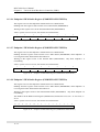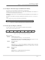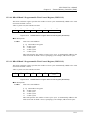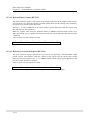
1
ML671000 User’s Manual
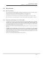
Chapter 11 Universal Serial Bus Device Controller (USBC)
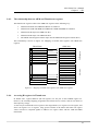
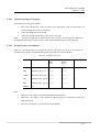
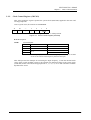
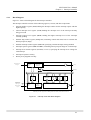
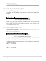
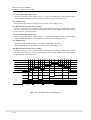
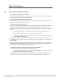
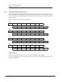
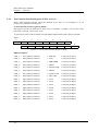
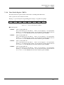
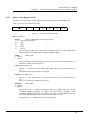
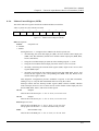
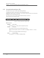
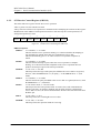
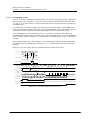
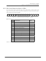
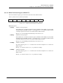
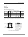
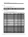
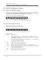
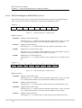
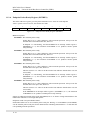
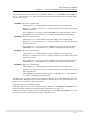
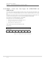
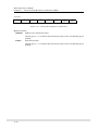
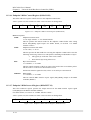
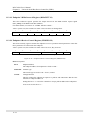
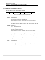
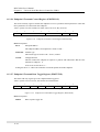
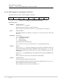
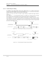
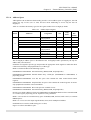
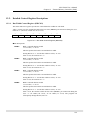
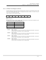
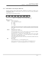
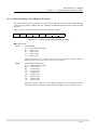
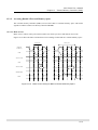
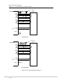
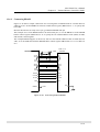
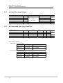
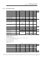
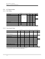
11.2.24. Endpoint 1 Data Toggle Register (EP1TGL)
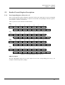
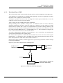
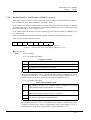
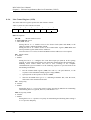
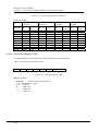
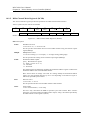
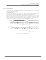
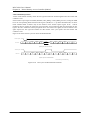
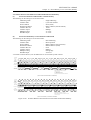
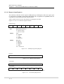
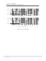
This 8-bit read-write register controls the endpoint 1 data toggle bit.
After a system reset or bus reset, the contents are 0x00.
7
6
5
4
3
2
1
0
-
-
-
-
-
-
TR
DTSB
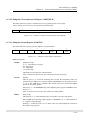
Dashes indicate nonexistent bits. Reading one returns “0” in that position.
Figure 11-32
Endpoint 1 Data Toggle Register (EP1TGL)
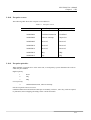
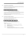
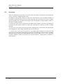
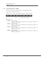
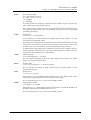
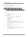
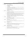
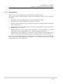
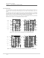
■ Bit Descriptions
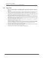
DSTB:
Data sequence toggle bit
Initialize endpoint 1 by setting this bit to “1” to reset it and the data packet toggle bit
to “0” and specify the DATA0 PID. The data sequence toggle mechanism then
automatically modifies this bit as part of its synchronization.
TR:
Toggle requirement
This bit is only valid when endpoint 1 is transmitting.
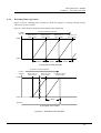
Setting this bit to “0” toggles DATA0 and DATA1 each time that endpoint 1
receives an ACK from the host.
Setting this bit to “1” produces the rate feedback mode, which toggles DATA0 and
DATA1 each time that the EP1TRDY bit in the endpoint packet ready register
(PKTRDY) goes to “1.”
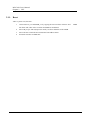
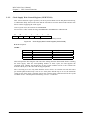
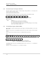
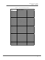
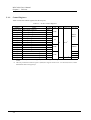
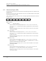
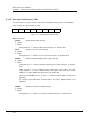
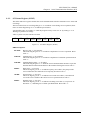
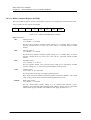
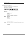
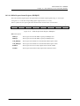
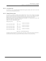
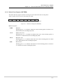
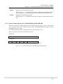
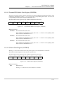
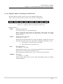
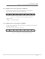
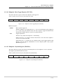
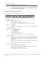
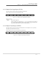
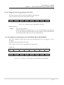
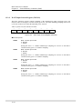
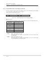
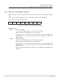
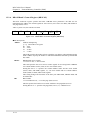
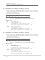
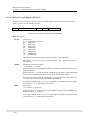
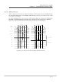
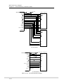
11.2.25. Endpoint 1 Payload Register (EP1PLD)
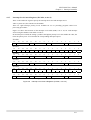
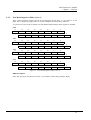
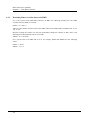
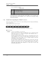
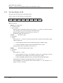
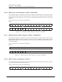
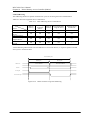
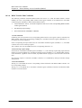
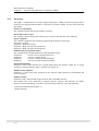
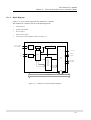
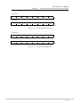
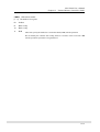
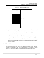
This 8-bit read/write register specifies the maximum packet size for endpoint 1 receive operations.
The highest specification allowed is 0x40.
After a system reset or bus reset, the contents are indeterminate.
7
6
5
4
3
2
1
0
-
Dashes indicate nonexistent bits. Reading one returns “0” in that position.
Figure 11-33
Endpoint 1 Payload Register (EP1PLD)
11-27