1
Operation
2.8
Control Signal Connection
2.8.1
Analog Operation
All E-618 versions can be operated by an analog control signal. The output
voltage (if in open-loop operation) or the actuator position (closed-loop
operation) is directly proportional to this analog control signal. The analog
control signal consists of two components:
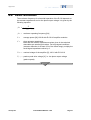
Analog control signal = CONTROL INPUT + DC OFFSET
where
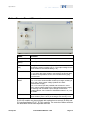
CONTROL INPUT is the voltage connected to the corresponding BNC
socket on the front panel
DC OFFSET is the DC offset voltage set via the corresponding potentiometer
on the front panel (0 to 10 V)
-2 to 12 V is the recommended range for the analog control signal, resulting
in -20 to 120 V piezo output voltage. A range of -3 to 13 V is possible and will
result in -30 to 130 V output voltage, but working with increased output
voltage will decrease actuator lifetime. See “Lifetime of PICMA® Actuators”
on p. 29 for details.
The signal applied to the CONTROL INPUT BNC socket can be generated
using a DAC-board in a PC. PI offers a LabVIEW driver set which can be
used with certain D/A boards. This driver set is compatible with the PI
General Command Set (GCS) LabVIEW driver set available for all newer
controllers from PI. In addition, PI’s patented HyperBit technology for
providing position resolution higher than that of the D/A board is included in
the E-500.ACD driver set (see "Model Survey and Upgrades" p. 7).
2.8.2
Remote Control via Computer Interface
E-618.1G models equipped with an E-517 computer interface and display
module can be controlled from a host computer via the TCP/IP, USB, RS-232
or IEEE 488 PC interface. See the E-517 User Manual for details.
www.pi.ws
E-618 PZ221E Release 1.0.0
Page 17