1
IIto{rrrnie
Mark IW* Locating SYstem
Operator's Manual
l-L
I
l--r,-
425S.W.41oSt.
.
I
)(
II
D--=-=-=b
Gorur*ctL
ITCOr|PGIFIATED
.Fax425-291-0005. Www.digitrak'com
Rerrton,WA98055USA. Phone 42*251-0559180G288.3610
-
D
I
elraI
Cc] NTFo L I NCoFsPo rlATED
Copyright O 2000 by Digital Control lncorporated. All rights reserved. July 2000 Edition.
Trademarks
Ihg o9l logo,_DigiTrak@, |GPS@, SuperSonde@, Datalog@,
and TransiTrak@ are registered trademarks and
EclipserM, FasTrakrM, LTrM, SuperCellrM, Mark lVrM, target in the boxrw, line in the -boxaM, and took-ahea{M
locating are trademarks of Digital Control lncorporated.
Patents
The DigiTrak@ Locating System is covered by one or more of the following U.S. Patents: 5,155,442; 5,337,002;
5,444,382; 5,633,589; 5,698,981; 5,726,359; 5,757,190; 5,764,062; S]At,AZa; 5,878,824; S,gtI,AAZ;
5,926,025; 5,933,008; 5,961,252; 5,990,682; 5,990,683; 6,002,258; 6,005,532; 6,008,651; A,Ol+,OZA;
6,035,951;6,057,687;6,066,955. Sale of a DigiTrak@ Receiver does not convey a license under any paients
covering the DigiTrak@ Transmitter or undergrou-nd drill housing. Other patents pending.
Limited Warranty
All products manu{actured and sold by DCI are subject to the terms of a Limited Warranty. A copy of the
Limited Warranty is included with your DigiTrak@ Locating System; it can also be obtained Uy contacting OCt
Customer Service, 800-288-3610 or 425-251-0559, or by -onhecting to DCI's web site, www.digitrak.com.
lmportant Notice
All statements, technical information, and
recommendations related
to the products of Digital control
lncorporated (DCl) are based on informalion believed to be reliable, but the accuracy or complete-ness thereof
is not warranted. Before utilizing any DCI product, the user should determine tfre suitabitity of the product {or
its intended use. All statements herein refer to DCI products as delivered by DCI and do not apply to any user
customizations not authorized by DCI nor to any third-party products. Nothing herein shail'constitrt"
warranty by DCI nor will anything herein be deemed to modify the terms of DCI's existing limited warranty
"ny
applicable to all DCI products.
FCC Compliance Statement
This equipment has been tested and found to comply with the limits for a Class B digital device, pursuant to
Part 15 of the Rules of lhe Federal Communications Commission. These limits are designed'to provide
reasonable prolection against harmful interference in a residential installation. This equipment generates,
uses, and can radiate radio frequency energy and, il not installed and used in accordance with the inltructions,
may cause harmful interference to radio communications. However, there is no guarantee that interference will
not occur in a particular installation. lf this equipment does cause harmful interference to radio or television
reception, which can be determined by turning the equipment off and on, the user is encouraged to try to
correct the interference by one or more of the following measures:
Reorient or relocate the DigiTrak Receiver.
lncrease the separation between the problematic equipment and the DigiTrak Receiver.
Connect the equipment into an outlet on a different circuit.
Consult the dealer or an experienced radio/TV technician for help.
Changes or modifications to the DCI equipment not expressly approved and carried out by DCI will void the
user's limited warranty and the FCC's authorization to operate the equipment.
1nifaat<a Mark tV Operator's
Manuart
l-t
<'-- It
I
l---'
DrGlrAL corurRoL lNcoFPoF'ATED
Table of Contents
Safety Precautions and Warnings
l
"-.....".'""'
tr
tr
Display Menu
Functions.....'.....-
""""""""""'
-7
'
A.
o
o
o
1n
-Pt Calibration .....".-."'.
2-Pt Calibration
1
12
"""""""""";;
.-....'..'.".
r\)
""""""""""' 14
1A
Units
Depth
Pitch Units
'la
Display.'..".
Screen
Mark lV Remote
Main lnformation
iuiiL"$i'#:::::::Power On/Of{
: ::
::
Telemetry Channel Selections
:::::::
'.......
Meter
lnstructions.
DataLog Function
Backlight On/Off
Hour
Remote Steering
giadanxa Mark lV OPerator's
Manuat
"""""""'.""""19
'
"""19
r)n
20
""""'""""'?0'
)1
"""21
"""""-"""""'21
""""""""'21
""""""""'22
DIeIraT CorurRoL INCoFPcf FATED
Safety Precautions
and Warnings
IvIPOETAIT NOTE: All operators must read and understand the precautions and warnings given
below and listed inthe DigiTrak Directional Drilting Locating System'Operator's Manuat.
g
e
Serious injury or death can result if underground drilling equipment rnakes contact with an
underground utility such as a high-voltage electrical cable or'a natural gas line.
Substantial property damage and liability can result if underground drilling equipment makes
contact with an underground utility such as a telephone, fiber-optic, watei oi sewer line.
Work slowdown and cost overruns can occur if drilling operators do not use the drilling or
locating equipment correctly to obtain proper perforrnance.
Directional drilling operators MUST at all times:
Understand the safe and proper operation of drilling and locating equipment, including the use of
ground mats and proper grounding procedures.
Ensure that all underground utilities have been located, exposed, anci marked accurately prior to
drilling.
'
'
I
.
.
.
Wear protective safety clothing such as dielectric boots, gloves, hard-hats, high-visibility vests
and safety glasses.
Locate and track the drill head accurately and correctly during drilling.
Comply with state and local governmental regulations (e.g., OSHA).Follow all other safety procedures.
Carefully review this manual and the DigiTrak Directional Dritling Locating System Operator's Manual
to ensure you know how to operate the DigiTrak System properly to obtain iccurate depth, pitch, roll,
and locate points.
Prior to the start of each drilling run, test the DigiTrak system with the Transmitter inside the drill head
to confirm that it is operating properly.
Regularly test system calibration while drilling using the ultrasonic function. Always test calibration
after you have stopped drilling for any length of time.
Test system for on-site signal interference. Background noise must be betow 150, and signal
strength must be at leasl250 points above background noise during all locating operations.
FEMEMBER: lf you 31e having difficulty on the job or if you have any questions about
the operation of the DigiTrak System, call DGI's Customer Service O6pirtmentat42S251'0559 or 800-288-3610 between 6 a.m. and 6 p.m. Pacific Time, nAonOay through
Friday, for assistance.
4
DIOIIAI COru'rROL INCOFPOFATED
Introduction
that enhance its performance
The DigiTrak Mark lV Locating systgin incorporates significant upgrades
easy-to-read graphic displays
have
over earlier Digirrak systems. The Mark lV receivers ind remotei
You simply use the graphic
ever'
than
easier
and menu-driven controls that make using
"nO-to.iting
box on the display window to locate the
disptay to guide you in positioning a tardei ior i fin"i in a
you can also i;;;i; using ine peak signal or plus/minus signs, as on earlier
transmitter in the driil head.
DigiTrak models.
packs, and battery chargers as
The DigiTrak Mark lV system uses the same transmitters, Nicad battery
t" rrrr-u* llt system. The Mark lV is also available as an upgrade to the Mark lll equipment'
lV Locating System' Many of the
This manual gives information and instructions for the DigiTrak Mark
in this manual
in the previous-DigiTrak systems, so we frequently recommend
principles are the ,u*L
how
understand
Manualto
Operator's
", Directionat iriiirg Loruting Sy?tem
that you refer to the DigiTrak
tab
the
behind
here
system
q-anya.l
locating
ot-tn"
to best operate the system. We have ptouiO"Ji
lnformation"
Locating
"opy
o11nt-"O1Oj]1ak
n99q?.clOV
divider marked "DigiTrak Locating tntormation;. f Vou
r""iion, please catiOigitat Controj lncorporated at 800-288-3610 or 425-251-0559'
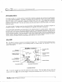
On/Oft
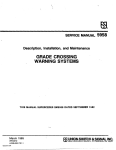
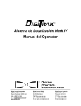
will then see the locating screen'
on - The Mark lV receiver is turned on by clicking the trigger once. You
are described in the next
below,
on the locatirig screen, as shown
The display symbols tn"t
section (see Page 6).
"pp""r
drcifnru<@ r\titf,K iY*
Telemetry
Channel Setting
Target in the Box
Locating DisPlaY
/r\'
12
[./
ou4r"o
,
Plus/Minus
Localing lndicator
.tsH
Transmitter Roll
(Clock)
PitchlRoll Update
lndicator
Transmitler Pilch
Feceiver Battery
Signal Strength
Transmitler BatterY
Transmitter TemPerature
Locating Screen
off
-
;;;.,
click the trigger until you reach the
To turn the unit off, you must first access the menu choices'
shut off the receiver'
hotd the trigger in during the countdown from 3 to 0 to
""r"tt
*"."
l(Dl,'tn"n
D c;maI
I
CoxIrRoL NcoFPorr,ATED
I
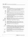
Display Symbols
Irr4ril
eEH
l-r
l-f
l-,
n
\4,
Telemetry channel setting - Shows the current channel setting for the receiver. The
receiver must be set to the same channel as the remote display. There are four
channel settings (1,?,3,4) and an off setting, which indicaies-that the telemetry
function is turned off and there is no signalto tne remote display.
Locating icon - Represents a bird's eye view of the receiver. The locating icon is
referred to as the "box" when using the target in the boxand tine in the bo\ locating
techniques.
Target - Flepresents the front and rear negative locate points (FNLP and RNLp). When
the receiver is positioned directly above a locate point, the target will be in the box.
-
L-ine Represents the positive locate line (PLL). When the receiver is positioned
directly above the PLL, the line willbe in the box. The PLL also allows ior off-track
locating when access over the tool is limited (see DigiTrak Directionat Driiling
Locating System Operator's Manual.
+/-
Plus/minus locating indicator * The plus or minus sign in front of the signal
strength value is used_to guide the operator in finding the locate points
1ffulp anO
RNLP) and the tocate tine (pLL).
+539
Signal strength - Displays the amount of signalfrom the transmitter. The signal
strength scale ranges from 0 to 999, where O indicates no signal and 999 indicates
signal saturation (receiver and transmitter are very close).
6
rtr--Clz
n
Transmitter battery
-
Depicts the transmitter's battery status.
E
Transmitter temperature - Shows temperature status of transmitter. An arrow
pointing up next to the thermometer indicates increasing temperature; an arrow
pointing down indicates decreasing temperature. A digitaltemperature reading is
displayed below the clock whenever the trigger is held in.
n
Receiver battery
l-l
t-l
- Depicts the receiver,s battery status.
l=l
* (r'"
,
O
12
'o'
6
6
Transmitter pitch - Represents the inclination of the transmitter (tool). The pitch can
be monitored in either percent slope or degrees. The pitch value will be shown with
the drill tool indicator behind it; the drill tool indicator will point up for positive pitch
and down for negative pitch. Note the smaller superscripied "0', after the "5', in the
transmitter pitch symbol. This smaller number represenis pitch in tenths of a percent
(0-1%) and is only displayed when using sensitive-pitch transmitters.
Pitch/roll update indicator - The dot in the center of the clock should blink every
2.5 seconds, indicating that current pitch and roll inlormation is being received from
the transmitter. This also means that transmitter battery and temperature status
updates are being received.
Transmitter roll
-
The clock shows the 12 roll positions of the transmitter (tool).
llr.a
l. D'=ltot co*t*ot
l*?ffi
General OPeration
screen (see page.5)' You can then
When you {irst turn on the Mark lV receiver, you see.the.locating
"Locating
lnstructions"' page 14)'
(see
access the menu functions, or you .rn prot""d to locating
trigger click advances you to the. next
To access the menu functions, you simply click the trigger; each
a menu setting, you hold th.e
menu function. Each menu has a countoo*n r.qrriJ".'To crraile
0, release the trigger and you will
trigger in while tne counter goes down to 0. once the counter reacheJ
has been changed- The display will then
hear three contirmatiJn- b;d; indicating triat ine menu setting
go back to the locating screen.
or predicted -dgptt"'., you hold the trigger
During locating, to display the transmitter_tempelature.and depth
at one of the three locate points: the
l.second
for
need to noH tre'iiigger in
in. Before locating vo[
"]ropoint (FNLp or iN[pi-or the positive locate line (PLL). This is necessary to lock
front or rear negative locate
it is with respect to the transmitter'
in on a re{erence signat ;tiength so that the receiver knows where
(shut it off and power it back up)
NOTE: lf you are changing a transmitter, you must reinitiate the receiver
you
ruit tn"n recalibrate the receiver using either the 1-point or 2after installing the new'tra-nsmitter.
point technique (see pages 10-1 1).
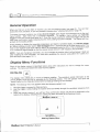
Display Menu Functions
for how to change the menu
Each of the display menus isldescribed below along with instructions
settings. The menus are listed in the order that they appear'
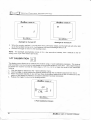
DATALOG
procedure sends information to the
This display menu allows: you to record a Datalog reading' The
The drill operator must push the
remote display at the drill rig for recording by th.b"taloimodule.
recorded'
be
,,record" button on th; O"tuf-Jg module bef6re a Datalog reading can
NoTE: The Datalog menu only appears when the telemetry system is on.
'1.
Z.
3.
Click the trigger to access the DataLog menu'
through the countdown sequence from
Hold the trigger in while holding tne receiveiievel and steady
3to0.
and-will see a checkmark at the
when the counter reaches 0, you will hear three confirmation beeps
Datalog module'
the
to
back
sent
been
dis;ht, inoicatin'g that a reading has
bottom of the
Diadaai<"Mnx iv^
a
dLJ
.L
lr<-l
-IaD6{
i#^'"
DataLog DisPIaY Menu
Drerral CorurRot rucoRpoFATED
I
Release the trigger to return to the locating screen.
1.
5' The remole_ display will also sound three confirmation beeps when it receives the receiver,s signal,
and the LCD reading on the Datalog module will be incremented by one
fails to increment one count, the above steps must be repeated.
count. lf the Datalof,unii
POWER
This display menu allows you to turn off the receiver power.
Click the trigger to advance to the power menu.
Hold the trigger in through the countdown sequence from 3 to 0.
1.
2-
Biadaai<',*r.ax iv-
3
o
l-){-|"P3'H
r,tr?ojm
-!
Power Off Screen
3' When the counter. reaches 0, you will hear three confirmation beeps and will see a checkmark
bottom of the disptay.
4. Release the trigger and the unit wiil shut off.
at the
ULTRASONIC
This display menu allows you to take an ultrasonic (height above ground) measurement.
Click the trigger to advance to the ultrasonic menu.
Hold the trigger in while holding the receiver steady through the countdown sequence from
2 to 0.
When the counter. reaches 0, you will hear three ionfirmition beeps and the
ultrasonic height will be
displayed along with a checkmark at the bottom of the display.
Release the trigger to return to the locating screen.
1.
?
3'
_
4.
9rcilaarcinnnx iv-
diadaait',*l.ar iv-
a
61
tt
=
e
t6JI tu=
L=
0!,VUVVUVVV
Frr
n
U
l-)r4l'3ru
t-
lffi^r6
-a
Ultrasonic Menu Ecreen
8
Successtul
U
ltrason ic Measu rement
D
r
eral
CorurRo
t-
I
trtco RPoFATED
ground or if the
above the. ground or sitting on the
NOTE: lf the receiver is less than 12 in. (30 cm)
you
will hear two
properly,t;; ;ii;;to.i.i"iOitig of 0 will be displayed'
uttrasonic function is not operating
at the bottom of the display'
long tones, and a crosJeJi1,".f irirk will appear
llrciFaan<"rvtfrtt iv-
g
Sacz
rlAlr.llrll/-v-lJlll4)llJlA! n
FT'N
u
rE
l-)<-l-IooKtrr bss.Disptay Showing Zero (0)
llltrasonic Measurement
TELEMETRY
tn"
tl" ]:l9T:tY,:h.1T1,1?tll?;,-tinj'"i[""][Xl??',.tn"t
to the same channel'
,'J:,ffl3lr'HH#"#il"ffiffi in"'iJr"t" oispray. fhe two must be iet
channer settins is dispraved.
advance to the teremetry men.r,w,.,:: y:.l"ent
,Til;,;;;;;;
;' ;;"d il;;;d;;; i" tr*'ghlne countdown ;::'g:: j:31:,:"^tbeeps and win see a checkmark at the
rhis dispray menu
3:.
arrows vou
il,iilTJ''"t"t;j,I,'il##:,';:;;';iiiilfit;;;nii|.*"lion
4. ?,?fffff|,'ffi.liTiXy;
5.
to chanse
t;"t;i;"
throush ail rive settinss-off,
trisger in, the channer settinss win cvcre srowrv
1,
and you will return to the locating screen'
the trigger when the correct setting is displayed,
9liadn'r.lt"*r.ax iu^
u,A-u lt{
e
t><|"ffi"""
TetemetrY Channel Setting
BACKLIGHT
off the display backlight'
This display menu allows you to turn on or
on the display' lf the
to the backright menu;..a right burb wit appear
1. crick the trigger to advanceo"lit
up;,if it isLff , the bulb will appear unlit'
backtight is on, tnJOirTO riff
sequence from 2 to 0'
Hold the trigger itlt[io'gh tn" countdown
2.
l.
Dremal corurRol trucoRr:oFATED
=
Draifaai<",llranx iv*
lliaifnnit'dvtax iv;itr
P
e
l-).-l'P3]*"
.-l
rxl#^ft
l-
Backlight Is Turned Otf
3'
.
4.
Backlight ls Turned On
When the counter reaches 0, you will hear three confirmation beeps
and the light bulb will either light
lp as the backlight comes on or it will become unlit and the backlight will turn oif.
Release the trigger to return to the locating screen.
NorE:
The backlight automatically comes on for a few seconds at
startup, then it defaults to the off
setting, even if you have reset it previously.
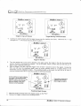
1-PT CALIBRATION
This display menu allows you to calibrate the receiver using 1-point
a
calibration procedure. The receiver
and transmitter must be turned on and placed ol thg gro.,iop"i"llelto
each othbr. ur" tape measure
to position the receiver so that its inside edge is 10 ft s in.
m)
from
the center of"the transmitter
is.ts
housing.
1.
'2.
3.
4.
Click the trigger to advance to the 1-point calibration menu.
Hold the trigger in while holding the receiver steady through the
countdown sequence from 5 to 0.
when the counter reaches 0, you will hear three ionfirmition teeps and will
see a checkmark at the
loqtom of.the display to indicate a successful calibration hJs been conducted.
Release the trigger to return to the locating screen.
.
llialfaant'twtnx iv-
5
l-)(-l'3flil
It
rild.&ih
-I
1
10
-Point Calibration Screen
Uidrli?,'ti(@ Mark lV Aperator,s Manual
D
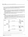
5.
reral CoN-rRoL Nco FPOF,ATED
I
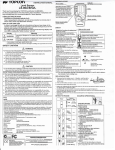
you must now verify that a successful calibration was made to ensure that you get accurate depth
check the depth (distance) in at
readings. you can use either of the two mJnoos OescriUed below to
depth' The sketch given below
least three locations, one of which snoirlJ b; ;iyour intended/target
for each method'
shows precisely how to place the transmitter and the receiver
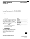
Method
1
ol the lejeiver measures a glven
distance irom ine centerline of the transmitter to the inside edge
amount;intheexampleshowninthesketch,adistanceof6ft5in.(1'97m)isused,Duetothe
(13-cm) allowance to the
position of the depth antennas in the receiver, you must add a 5-in'
distance You intend to check.
(13-cm) allowance.
that the oeptn"snown will be the measurei distance minus the 5-in.
'n
Method 2
a given amount; in the
centerline of the transmitter to the bottom of the receiver measures
exampleshowninthesketch,adistanceof6ft(1.83m)isused'
not need to add the 5-in' (13-cm)
thar the deptfi"shown will match'the measured distance. You do
method; however" it can be difficult to view the display for depth
antenna attowince using this
readings.
Method
1
6
ft 5 in. (1.97 m)
Mark lV
Receiver
(top view)
Transmitler
in DrillHead
Method 2
6
ft
(1.83 m)
Mark lV
Receiver
(side view)
61171/zin. (2.02 m)
Depth Antenna
Centerline
.Depth tolerance is 5%; thus, at a distance of 6 ft (1'83 m), the error tolerance is 3'6 in' (9 cm)'
D
terra.l Co rurRo
L I NcoFapoFtATED
z-PT CALIBRATION
Thls display menu allows you to calibrate the receiver with the transmifier in the ground
using a 2-point
calibration procedure' The receiver and transmitter must be turned on, and the "receiver
must be held
directly over the transmitter and about 12 in. (30 cm) above ground. The transmitter's pitch
needs to be
less than !2C,/" for the calibration to be accuiate. tiuring th6 2-point
calibration procedure, the receiver
must be.raised straight up at least 20 in. (51 cm)*be iure to hold the receiver
levet and in the same
plane with the transmitter.
1. Click the trigger to advance
to the 2-point calibration menu.
0rcdnti<',*uw iv-
g
PI
vvvvvvuwvv
IRL
5
E:T
l\
4ro!,o,!
l-)(-l
:.?*.,."
2-Point Calibration Screen
2.
-
First point
Hold-the trigger in while holding the receiver level and steady through
the countdown sequence from
5to0.
3.
4.
When the counter reaches 0, you will hear three confirmation beeps and will
see a checkmark at the
bottom of the display.
Release the trigger, and the display will show the receiver (side view)
with p2 on the display and the
countdown willbe restarted at 5.
fl
PE
vvvvvvvvw
r
IHL
3
r{f...F
2-Point Calibration Screen
5.
6.
7.
8.
9.
-
Second point
Raise the receiver straight up at least 20 in. (5i cm), and then hold the trigger
in.
When the counter reaches 0, you will hear tirree confirmation beeps anO witt
see a checkmark at the
bottom of the display to indicate a successful calibration has been conducted.
Release the trigger to retLlrn to the locating screen.
The 2-point procedure may need to be completed a few times to get a good
calibration.
Flefer
to the DigiTrak-Directional Drilting Locating System Oferator's Manua!(Receiver Section,
under "Calibrating the Receiver") for instructions on how to verify a proper 2-point calibration.
t.
.tt
Oiadnaxa Mark tV Operator\ Mmuat
ONTFIOL INCOFPOFATED
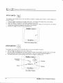
SELFTEST
receiver' This test must be
This display menu allows you io conduct a sell-diagnostic test .on-th^erange'
within
conduct;d in an interfer"n.e-fte" area with no active transmitters
1. Click the trigger to advance to the selftest menu'
from 2 to 0, and then release the trigger'
2. Hold the trigger in tnroujfrlne countdown sequence
then you wiil hear three confirmation beeps
3. when the counter reaches 0, there wirr oe a-pause and
a'fault is detected' lf a fault is detected'
and will see a checkmark at the bottom or tfre ltpfay, untess
the nature of the problem (for example'
you wilt see Err displayed along with
"rioi.oiJinOi."ting
"n is
Oa"f.EornO noisll. Before continuing' you must troublethe 001 error code indicates that there
shoot tne problem or retest in a different area'
0iaila,u<*;vax iv"
Diaifd,rrit"'tlanx iv^
E"
W
zu
rh
rL
ra.Dc4
l-><-l
g
nn,
uut
e
l-><-l
-rtoE4
Fffi^,.
H:e.".
Selftest Error Screen
Selftest Menu DisPlaY
DEPTH UNITS
values (depth and temperature) in
This display menu allows you to set.the Mark lV system to display
either English (fVin. and 'Fi or metric (m/cm and 'C) units'
The display will indicate the current setting'
1. Click the trigger to advance to the depth units menu'from
3 to 0.
sequence
2. ioio tne tri;der in through the countdown
beeps and will see the unit setting
confirmation
3. when the counter reaches 0, you will hear three
change and a checkmark appear at the bottom of the display'
4. Releise the trigger to return to the locating screen'
9iaifaax" ivax iY-
3
DePth llnits DisPlaY Menu
13
DIemaI CorrrRoL INCC]FPOFATED
PITCH UNITS
This display menu allows you to set the Mark lV system to display pitch values in either degrees or
percent of slope.
the trigger to advance to the pitch units menu. The display will indicate the current setting.
1 Click
2.
Hold the trigger in through the countdown sequence from 3 to 0.
3' When the counter reaches 0, you will hear three confirmation beeps and will see the unit setting
change and a checkmark appear at the bottom of the display.
4. Release the trigger to return to the locating screen.
9iaifa*t'avtaxiv-
3
I\
l-)(-l'TOU
Etrl
RsH,,-
Pitch Units Display Menu
HOUR METER
This display menu allows you to view the actual run time for the Mark lV receiver.
Click the trigger to advance to the hour meter menu.
The hour meter will display the run time in hours, minutes, and seconds, and the hand on the clock
yjll be rotating to count down 5 second increments. (You do not need to hold the trigger in.)
The display will return to the locating screen when the trigger is clicked once.
1.
2.
^
3'
12
\-/
a ,4.1.
Seconds
KHR6^
Minutes
I\
l-><-l-r60brd f,s^]lg.,-
Hour Meter Display
,+
1^
Diadnaxa Mark lV Operator;s Manuat
llt.l
I' D,.'tot
co*t=ot'*"ol*
Locating lnstructions
Handling the Receiver
receiver correctly to obtain accurate readings' You
IMPoRTANT NOTE: lt is critical that you
-and hold the
maintain a constant height-above-ground distance'
must hold the receiver level at all times
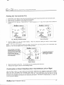
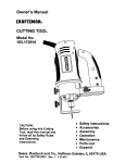
Marking Locate Positions
The front and rear negative locate points (FNLP and
RNLP) and the positive locate line (PLL) must be found
and accurately marked during the locating procedure'
To mark a locite position after you have found it, stand
with the receiver level immediately above the locate
point. Look down the verticalaxis that runs through the
center of the display to proiect a plumb line to the
ground. The poini where this plumb line hits the
ground is the location that you should mark.
Vertical Axis
Center ol
Display
Front of
Receiver
HINT: lf you mark ihe FNLP and the RNLP' and then
find the PLL, you can determine the exact location ol
the transmittei/tool. lt will be immediately below the
point where the line connecting the FNLP and the
ifNp intersects the PLL. For complete information on
the FNLP, RNLP, and PLL, see the DigiTrak Directional
Dritting Locating System Operator's Manual'
Ptumb Line for Marhing Locate Points
Locating the Transmitter
while it moves, whether
with the Digirrak Mark lV, you can locate the transmifier/tool and its heading
either facing toward or
tool
the
locate
also
standing in front of it, behind t, or toward ine side. You can
away from the drill rig.
in front of it, facing the drill rig' This is
The following technique guides you to the tool while standing out
the borepath curves, you may be
the recommended method for locating. ns vou continue to-drill or as
facing the last marked locate point rather than the drill rig'
The FNLP gives you the heading of
The first position to find is the front negative locate point or FNLP.
the tool is deperrdent upon the tool's
of
the tool and the predicted tool depth. The FNLp's distance ahead
be. The FNLP is represented as a
will
FNLP
front
the
depth and pitch; the deeper the tool, the further in
target O on the receiver's display.
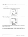
Finding the FNLP
a distance approximately 2 timesthe assumed depth"
1. stand out in front of the tool (facing the drill) at locr
the signal, then begin walking toward the drill'
2. Hold the trigger inJor t second "no ,"L"i" to ininthe
tof lefi corner ot tne display and the signal
3. As you approach the FNLP, 16. t"tg*tlppeats
strength increases'
giaifruti<t Mark tV Operator's
Manual
15
DIerau CorurRoL INCOFPOF]ATED
itl,RK iv"
Elixdaai<"avtnx iv^
/r\
12
I,,A,,t
eft
12
'Lr'
IJ
- + Ll15
a'
dmiir -EZ
l\
rrcoah
l-r<-l ffi.*
r
n
rii
o
eU
fi"+SBE
+u4r"^
,
tr,A,,l
r-r\
I
6'
r''r
r=t
l=l
r{I-iiEEZ
Target in Top Left Corner
[r'
+udan
,
nEl
t$ t=l
Target Moving Toward the Box
Continue to walk forward until the target moves into the tracking icon
changes to a "-", like it does with the Mark lll system.
(box). Note that the ',+" sign
Diadaan<',*:rnx iv*
12
u'A'u
F
o
er'
tcl
" -539
a.
O
J
ul^
+
qc"'
,
EE
r{Iiiifllz
l><t'p**.,?
Target in the Box
Turn the receiver 90" to the tool's direction, and again center the target in
the box by moving the
receiver forward or backward as needed. This is th; FNLP, which is ri,here
tn" toot wiil end up if it
does not get a steering command.
6. With the target in the box, hold the lrigger in for at least '1 second
to lock in the signat. During this
time, you will see the predicteo oept[ (with an arro* poinling down to i"ig;t
ahead of the
transmitter) and the ultra.soric height. The predicteo depih is thi depth the"tooli"iir
O" ar when it
reaches this point (the FNLp) if you do not give a steering command.
Arrow pointing to target indicates
the target is in the box and lhe
receiver is above the FNLp or the
RNLP. lf there is nol an arrow,
then the reading is the slant
distance to the lransmitter.
q
-rn
c'u
\
- .,n'
,a>{
c.
6
g6F"'
5uoFrN
r{@Dt---o
EH
Predicted Depth Screen
7.
8.
{A
rv
Mark the location directly below the display screen as the FNLP.
Release the trigger to return to the locating screen.
Ct
Transmitter temperature
replaces pitch reading
when trigger is held in.
Dretral Coxlraol NconPoFATED
I
Finding the Tool and the PLL
1.
2.
3.
4.
rod locate point'
At the FNLp, turn again to lace the tool (and drill) and walk forward toward the last
Note that the PLL appears in the top left of the display.
Walk forward and the PLL moves closer to the box'
with the Mark lll
Center the pLL in the box. Note that the "-" sign changes to a "+" sign, like it does
system.
Digdanx'xvtmc iv*
Digdeax"rran"< iv*
12
12
{r,A"t
p
9
e$
f:/'
" -53J
6
auEgf
,
tr'A"t
ou4r"o
0Et
l$ tEt
5.
Moving Toward the
e$
" +599
6
-wEEr
(3).
,
oulr"o
CI
t=l
l$ lEl
l><ri$b'.
t><rFe."
PLL
I
Box
Line in the Box
Hold the trigger in to see the depth display. Note the ultrasonic setting to verify a correct heightabove-ground measurement.
NOTE: The arrow that appears below the depth measurement and that points to the transmitter also
appears on the remote display when a depth reading is taken'
Arrow pointing to tool head
indicates lhe line is in the box
and the receiver is above the
transmitter or the PLL. lf lhere
is not an arrow, then the
reading is the slant distance
lo the transmitter.
a
I
en
I
/r\
't2
'f?'
!AbI{)!JJ{.VJryJI
6
Transmitler temperalure
replaces pitch reading
when trigger is held in.
+
fi, ttn"
DePth Screen
6.
7.
Mark this location as the PLL. You should now be standing above the tool'
Release the triEger to return to the locating screen'
Confirmation of Exact Heading when Tool Deflects Left or Right
locate point or RNLP'
Like the FNLP, there is a point behind the transmitter called the rear negative
transmitter's heading'
the
represents
When the FNLp and RNLP are connected, they make a line that
points
and the PLL to find
locate
pLL
the
using
is the positiori of the tool.
where this line intersects the
as a target O
is
represented
RNLP
T[e
peak
signal'
the tool is more reliable and efficient than using the
on the receiver's disPlaY.
llt.a
I' Drerar corurnoL- rNCc:Fr,'oFATFn
Finding the RNLP
1.
While standing above the tool still lacing the drill, continue walking toward the drill; the target will
appear in the top left corner of the display and the signal strength will decrease.
9,ixifaant,,**tx iv-
/r\
12
c
9
u'A'u
effi
H
- +5gg
6
{Eri-F
t',
3
ul,
+
, 5c'
nr
rli
tiJ
r:
l!
l\)r-l'Ps'ir
Target in Top Left Corner
2.
Walk forward until the target moves into the
does with the Mark lllsystem.
box. Note that the
"+" sign changes to a
"-" sign, like it
12
u'A'u
r=r
e{H
(s)'
fi *539
I'dno
ffi-cE7
bt l=il
"
a'
l]El
Target in the Box
3. Turn the receiver 90" to the tool's direction and again put the target in the box by moving the receiver
forward or backward as needed.
4. Mark this location as the RNLP.
5. Connect the RNLP to the FNLP by a line. This line represents the transmitter/tool's heading.
NOTE: lf you hold the trigger in at the RNLP, you will see a predicted depth reading. This depth is only
valid at the FNLP and must be ignored at the RNLP. The receiver cannot discern beiween the RNLP ani
ihe FNLP.
18
CialfaaNa Mark tV Operator's Manual
llr.ll'D''''o
Mark lV Remote DisPlaY
screen is configured in the same way as that on the receiver, and it uses the
The Mark lV remote display
'The remote displaf, however, has.a main information screen and then only four
same display symbols.
The main
menu opiion* (po*ei on/off, telemetry'cninnet selection, backlight on/off, and hour meteQon
information
Specific
information screen is described below, and then the menu options are explained.
Datalog
with
a
and
transmitter
with
a
cable
remote steering with the Mark lV remote display and its use
mapping system is also included.
Main lnformation Screen
The main information screen shown below is displayed when you turn on the Mark lV remote display unit.
The on/off button on the remote works similar to the trigger on the receiver. The speaker on the remote
warns the operator if the transmitter's temperature is increasing-temperature increases are accompanied by tones from the speaker to indicate that appropriate_and immediate attention is required- The
speaker ilso emits tones during the Datalog function when a Datalog reading is received'
Remote Steering lndicator
s{ O13
eU \./
lljL.yrLJAlJllr.JlJ
{uAu)
in
RK iv'"
"
', t
J-L -1
;tsH
SAg ^
Remote DisPlaY Battery Status
Front of Mark IV Remote DisPlaY
positive locate line
The main information screen changes when the receiver is over the transmitter or the
to indicate
pointing
the..transmitter
to
it
has.an anow.below
lell;, as shown uenwl rne oept-n reading
is not
lf
there
distance'
slant
rather
the
than
PLL
in"t in" reading is the ictual depin of the trinsmitter or
is
the
the
distance
graphic),
then
the
above
(as
shown.in
pointing down from tn6 Oepth reading
in
depth'
"iror
the
actual
slant distance to the transmitter rather than
Oir;ifaax^ Mark tV Operator's Manual
.A
r:'
DIeI.ral CorurRoL INcoFPOF,ATED
Arrow pointing to tool head
indicates the line is in the
box and the receiver is
above the transmitter or th'e
PLL, lf there is not an arrow,
then the reading is the slant
distance to the transmitter.
("A")
PCH \^-/
r -**ff
+ud"
JtsH
\
Jtn*'2
Depth Reading When Receiver ls Above Transmitter or pLL
By holding in the onioff button for 2 seconds or more, the transmitter temperature is displayed in place of
the pitch informalion, as shown below. Note that the arrow below the depih reading is poiniing to a target
in front of the transmitter-this indicates that the receiver has the target in the box-and is above the fr6nt
or rear negative locate point (FNLP or RNLP). lf the receiver is over the FNLP, then the reading is the
predicted depth' lf there are no arrows with the depth reading, then the distance is the slant
distlnce to
the transmitter rather than the actual depth.
Arrow pointing to target
indicates the target is in
the box and the receiver
as above the FNLP or the
RNLP. It there is not an
arrow, then the reading
is the slant distance to
the transmitter,
r"Aur
eft
{I;il;
.*Jl
el ols
\r-l.
s6F'
Transmitter temperature
is displayed when on/off
button is held in.
Up or down arrow
indicates increasing
or decreasing trend
in transmitter
temperature.
Predicted Depth Reading When Receiver ls Above FNLP or RNLp
with on/off Button Held in to Display Transmitter Temperature
Menu Options
The menu options are accessed in the same way as on the receiver. click the on/off button to get to the
menu screens, and then hold the bufion in for the countdown.
Power On/Off
With the power on/off menu displayed, as shown in
the picture to the right, hold the button in for the
countdown sequence from 3 to 0 to turn the unit off.
3
o
29
Crcilanxt
Mark IV OperatirZ Uanuat
D
r
eraL Coxt.rTRoL
I
NCOFIF]CfF.ATED
Telemetry Channel Selections
The telemetry channel menu, shown in the picture
on the right, allows you to change the telemetry
channel setting. Hold the button in to cycle through
the four channel options (1,2,3,4), and release
((,
rl)
A^
$H
3
when the desired setting is selected.
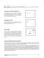
Backlight On/Otr
At the backlight on/off menu option, shown in the
picture on the right, hold the on/off button in to turn
the display backlight on or off.
"ft
3
12
Hour Meter
The hour meter menu option displays the amount
of time that the remote display unit has been
running (turned on). ln the picture on the right, the
hour meter shows that the remote display unit has
"12
been running for 2,145 hours, 35 minutes, and
seconds. Click the on/off button once to exit the
hour meter and return to the main information
P
b
KHR
,f.)\.
\-/
Hsffi
b
t)
'L
screen.
Remote Steering lnstructions
refer first to
lnstructions for using the Mark lV system for remote steering are given below' ...Please
System
Locating
Drilling
Directional
DigiTrak
inthe"
section
Steering" unoeitne Remote"Display
Operator,s Maniatfor instructions on how to set up the equipment.
depth reading.and,
Once the transmitter is lined up with the receiver, the arrow will appear b9lo1v the
will blink. lf the
indicator
steering
remote
the
of
the
center
when perfectly atigned, tn" i"rd.t symbol in
on
the direction in
depending
flashing,
will
start
right
left
or
the
to
tool gets off course, tn'en tne irrowi
right of the
*r,i.fr it has gone ott course. The further the tool goe! off course, then the further to the left or will slart
symbol
target
t"ig"t,vroo] tne flasning irro*r will be. For eximple, the arrow to the left of the
further to the left of
arrows
the
left,
then
goes'further
to
the
I
ai
left,
and
to
the
deviatis
blinking if the tool
the target symbolwill be flashing.
,'Remote
21-
llr aa I' Drerra.r corurnor rrucoRpc:FrATED
t'!A")
Arrow pointing to
tool head indicates
transmitter is lined
up with receiver.
;(i,
e#
vuv{/vvvvvv
+
+u4"o
,
1] r:l
t$
lEl
Display During Remote steering when Transmitter is Aligned with Receiver
Cable System
When using the cable transmitter, a "c" will appear next to the channel setting, indicating that a cable
transmitter is being used to send the data to the remote display. The "c" will flash each time a pitch/roll
update is received from the cable transmitter.
sl
Flashing "c"
lndicates Cable
Transmitter
Ofs
rr,A,;|};rfH \_/
OCF-
588n"
dil-ir=rz
Ju
ts
E
Remote Display when Cable Transmitter Is Used
NOTE: The liashing "c" may appear when not using the cable transmitter if the remote display receives a
very strong signal from a battery-operated transmitter within very close range (5 ft or 1.5 m).
DataLog Function
The DigiTrak Mark lV remote display unit works differently when using the Datalog function than earlier
DigiTrak remote displays. The correct procedure for taking a DataLog reading using the Mark lV system
is given below. Please also refer to the DataLog Operator's Manudl.
Press the owrite" button on the Datalog module to place the unit in standby mode, which is indicated
by a flashing LCD on the Datalog module.
2. At the Mark lV receiver, record a Datalog reading (see instructions on page 7).
3. The remote display will sound three confirmation beeps when it receives the Datalog information,
and the LCD count on the DataLog module willbe incremented by one.
1.
22
trIrcifwwa Mark tV Operator's Manuat