1
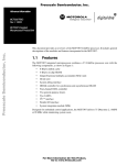
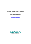
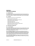
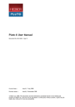
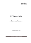
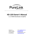
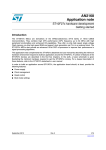
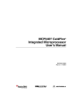
Order this document by AN2168/D AN2168 Semiconductor Products Sector Application Note ColdFire Microprocessor DMA Controller By Melissa Hunter Austin, Texas Introduction This application note discusses the use of the DMA (direct memory access) module available on several of the ColdFire processors. This list includes the MCF5206e, MCF5307, and MCF5407. The DMA modules on all three of these processors are very similar, and most of the information in this application note can be applied to all three. The DMA module on the MCF5272 is also similar, although it does not have all of the features offered by the DMA on the other processors. For this application note, all of the examples and code have been run and verified on the MCF5307. However, the same code can easily be adapted to run on the MCF5407 and MCF5206e. NOTE: Refer to the user’s manual and device errata for the processor to be aware of any limitations of the DMA module for that particular processor. ColdFire is a registered trademark of Motorola, Inc. © Motorola, Inc., 2001 TM Application Note What Is a DMA Controller? The DMA controller allows large blocks of data to be transferred without intervention from the CPU (central processor unit). Once the DMA registers have been programmed, a transfer can be started that will relocate data from one memory location to another or write data to/from a peripheral. Why Use the DMA Controller? When the DMA transfers data, it isn’t necessarily faster than using a series of move instructions to relocate the data instead. In fact, the timing for the bus cycle usually will be the same regardless of whether the DMA or the core initiated the access. However, the DMA can increase the overall performance of the system by freeing up the core to execute code that is stored in cache or the on-chip SRAM (standby RAM module). This has the inherent drawback that cache coherency is not maintained when using the DMA, and the DMA cannot transfer data to or from the on-chip SRAM. What Do DMA Bus Cycles Look Like? The ColdFire user’s manuals don’t show DMA-specific timings for full bus cycles, because there isn't a difference in the timing for a bus cycle initiated by the core and a bus cycle initiated by the DMA. When performing a DMA transfer, as long as the alternate master (AM) bit for the corresponding chip select or DRAMC register is cleared, the DMA address can still “hit” in the associated chip select or DRAM (dynamic RAM) region. Therefore, the bus cycles will appear the same as a non-DMA (ColdFire core) access to the same address since the timing (wait states, CAS latency, etc.) will be controlled by the same register settings. The timing, control signals, and strobes will be the same, only the transfer type and transfer modifier information will be different. So if the DMA source or destination address “hits” in a chip select space, then the chip select control registers will define the bus cycle (wait states, bursting, etc.). AN2168 2 MOTOROLA Application Note What Do DMA Bus Cycles Look Like? For example, Figure 1 shows a software-initiated, word-sized bus cycle to address 0xFFE00400. Figure 1. Chip Select-Initiated Bus Cycle AN2168 MOTOROLA 3 Application Note Figure 2 shows another word-sized bus cycle to 0xFFE00400. The chip select settings are the same, but this time it is a DMA-initiated bus cycle. Figure 2. DMA-Initiated Bus Cycle When comparing the two bus cycles, the basic timing properties are the same. Both bus cycles take six clocks (three wait states) to complete. In Figure 1 there are two dead clocks after the deassertion of the chip select and before TS asserts for the start of the next bus cycle. The DMA will result in back-to-back bus cycles, so in Figure 2 there are no dead clocks between bus cycles. By eliminating dead clocks and allowing the core to run code from internal memory, the DMA can be used to transfer large blocks of data more efficiently than the core itself. AN2168 4 MOTOROLA Application Note Dual and Single Address Modes Dual and Single Address Modes The DMA controller has two primary transfer modes: • Dual address • Single address Dual Address Mode Dual address mode is the most straightforward DMA transfer mode to implement. A dual address transfer consists of two phases. There is at least one read from the source address followed by one or more writes to the destination address. The number of reads and writes will depend on the source and destination sizes programmed in the DMA control register (DCR) as well as the port size for the source and destination address. Dual Address Mode Example 1 For example, the MCF5307 is programmed with the following chip select parameters: CSAR0 = 0xFFE0 ; base address = 0xFFE00000 CSMR0 = 0x000F0001 ; address range = 0xFFE00000-FFEFFFFF CSCR0 = 0x0D80 ; 3 wait states, auto-acknowledge, 16-bit port CSAR1 = 0x2000 ; base address = 0x20000000 CSMR1 = 0x00000001 ; address range = 0x20000000-2000FFFF CSCR1 = 0x0158 ; 0 waitstates, autoacknowledge, 8-bit port, burst enabled The DMA is programmed with the following values: DSR = 0x01 ; clear status register SAR = 0xFFE00400 ; source address = 0xFFE00400 DAR = 0x20000000 ; destination address = 0x20000000 BCR = 0x002 ; transfer 2 bytes DCR = 0x006B ; source = 16-bit, destination = 8-bit AN2168 MOTOROLA 5 Application Note Figure 3 shows the resulting dual address DMA transfer. Since the DCR[SSIZE] is programmed as word and the chip select mapped to the source address (CS0) is also a word port size, there is a single read from the source address. However, the destination size and chip select are both programmed as bytes. The DMA controller needs to write the full 16 bits of data to the destination, so the read is followed by two byte-size transfers to the destination address. Figure 3. Dual Address Transfer, SSIZE = word, DSIZE = byte AN2168 6 MOTOROLA Application Note Dual and Single Address Modes Dual Address Mode Example 2 To achieve a higher DMA transfer rate, the DMA settings from the example in Dual Address Mode Example 1 could be changed so that the destination size is also word. Use the following DMA settings: DSR = 0x01 ; clear status register SAR = 0xFFE00400 ; source address = 0xFFE00400 DAR = 0x20000000 ; destination address = 0x20000000 BCR = 0x0002 ; transfer 2 bytes DCR = 0x006D ; source = 16-bit, destination = 16-bit and the same chip select settings. Figure 4 shows the DMA transfer with the source and destination both set to word. Just as before, there is a single read from the source address, but now there is a word burst to a byte port at the destination address. Since CS1 is programmed to allow bursts and the DMA requests a transfer size larger than the chip select’s port size, a burst transfer results. Figure 4. Dual Address Transfer, SSIZE = word, DSIZE = word AN2168 MOTOROLA 7 Application Note Programming the DMA source size and/or destination size to use bursting bus cycles when possible can help to increase the overall performance of a DMA transfer. The example in Dual Address Mode Example 1 does not take advantage of the fact that CS1 is programmed to allow bursting. The entire DMA transfer shown in Figure 3 takes 12 clock cycles to complete. However, the second example does take advantage of the chip selects bursting capability, so the DMA transfer in Figure 4 only takes 10 clock cycles to transfer the same amount of data. Setting the destination size to 16-bit instead of 8-bit eliminates two clock cycles. If the byte count used for the examples had been larger, then even more clock cycles would have been eliminated by using the 16-bit destination size. For example, if the transfer byte count had been 100 bytes instead of 2, then example 2 would have completed 100 clock cycles faster than example 1. Single Address Mode In a single address transfer, only one bus access is performed — a read or write to the source address. The S_RW bit in the DCR determines the state of the R/W line during the transfer. Since there is only one bus cycle, single address mode requires external logic to decode the access and generate the necessary signals for the second device or an external peripheral that has built-in logic that will decode the bus cycle. Single Address Mode Example Figure 5 shows a single address transfer to address 0x20000000 using the following chip select settings: CSAR1 = 0x2000 ; base address = 0x20000000 CSMR1 = 0x00000001 ; address range = 0x20000000-0x2000FFFF CSCR1 = 0x0158 ; 0 waitstates, autoacknowledge, 8-bit port, burst enabled Then the DMA is programmed with these values: DSR = 0x01 ; clear status register SAR = 0x20000000 ; source address = 0x20000000 BCR = 0x0002 ; transfer 2 bytes DCR = 0x01D1 ; single address, R/W = 1, source=8-bit AN2168 8 MOTOROLA Application Note Dual and Single Address Modes Figure 5. Single Address Transfer, SSIZE = byte In this example, the chip select is programmed for a zero wait state 8-bit port. The DMA is set up for 8-bit single address transfers with R/W high. AN2168 MOTOROLA 9 Application Note Continuous and Cycle Steal Modes In continuous mode when the internal or external DMA request is received and the DMA transfer starts, the DMA will continue to transfer data until: • A multiple of the BWC value is reached — The DMA will release the bus when the BCR reaches a multiple of the value programmed into the BWC. • The transfer completes — The BCR reaches zero, the DMA terminates with an error, or the DONE bit is set by software (internal request only). In cycle steal mode, there is one DMA transfer per request. Instead of running multiple bus cycles until the entire byte count is transferred, there is just one read and one write phase for each request (only one read or write phase for single address mode). For example, transferring 32 bytes of data from a longword port to a byte port using cycle steal mode requires eight requests. For each request a longword is read from the source, and then the same longword (four bytes) is written to the destination. Since each transfer decrements the BCR by four, it will take eight transfers to move the entire 32 bytes (32/4 = 8). When the eighth transfer completes, the BCR will be cleared and the DONE bit in the DSR will be set to indicate the completion of the entire DMA transfer. Request Modes The DMA controller has two different types of requests that can be used to start a DMA transfer: • Internal requests • External requests AN2168 10 MOTOROLA Application Note Request Modes Internal Requests For an internal request, software sets the DCR[START] bit to begin a DMA cycle. Using internal DMA requests is straightforward. Since the DMA is started by software, there aren’t any timing concerns to worry about. However, be careful when setting the DCR[START] if the DCR[EEXT] is also set, since this could lead to conflicts with an incoming external request. NOTE: External Requests All of the previous examples in this application note have used an internal request to start the DMA transfer. A DMA transfer also can be requested by asserting the DREQx line. To have an external request start a DMA transfer, the DCR[EEXT] must be set; otherwise, the assertion of DREQx will be ignored. At a minimum, DREQx should be asserted for one rising clock edge (it will also need to meet the setup and hold time requirements with respect to the clock edge). The maximum time DREQx can be held depends on the configuration. In continuous mode, DREQx should be deasserted before the end of the DMA transfer. However, in cycle steal mode, the DREQx must be negated early enough or additional unwanted transfers could occur. If you are using dual address cycle steal mode and only want one DMA transfer, then DREQx should be negated before the write portion of the transfer starts. For single address cycle steal mode, DREQx must negate before the DMA transfer starts to prevent additional transfers from occurring. External Request, Cycle Steal Mode Example Figure 6 and Figure 7 show a cycle steal DMA transfer using the external request mode. This example uses the following chip select settings: CSAR0 = 0xFFE0 ; base address = 0xFFE00000 CSMR0 = 0x000F0001 ; address range = 0xFFE00000-0xFFEFFFFF CSCR0 = 0x0D80 ; 3 waitstates, autoacknowledge, 16-bit port CSAR1 = 0x2000 ; base address = 0x20000000 CSMR1 = 0x00000001 ; address range = 0x20000000-0x2000FFFF CSCR1 = 0x0158 ; 0 waitstates, autoacknowledge, 8-bit port, burst enabled AN2168 MOTOROLA 11 Application Note The DMA module is programmed with these values: DSR = 0x01 ; clear status register SAR = 0xFFE00400 ; source address = 0xFFE00400 DAR = 0x20000000 ; destination address = 0x20000000 BCR = 0x0004 ; transfer 4 bytes DCR = 0x606A ; cycle steal, ext. request, source=16-bit, destination=8-bit Figure 6. Cycle Steal Transfer Using External Request Mode — 1 AN2168 12 MOTOROLA Application Note Request Modes Figure 6 shows the first word transfer of the DMA cycle. Cursor 1 marks the assertion of DREQ. After DREQ asserts, the processor completes the current bus cycle and grants mastership of the external bus to the DMA channel. Since the DMA is programmed for cycle steal mode, there is just one read and one write phase. The basic DMA transfer timing is the same as shown in Dual Address Mode Example 1. After the first DMA transfer completes, the BCR is decremented by two. Bus mastership is then returned to the core and a normal mode bus cycle starts at cursor 2. Figure 7. Cycle Steal Transfer Using External Request Mode — 2 Figure 7 shows the transfer of the second word. Cursor 2 marks the beginning of the same normal mode access, as shown in Figure 6. Again the DREQ signal is asserted to indicate an external DMA request to the ColdFire. Once the DMA channel gains mastership, another read and write phase is started (cursor 1). After the write phase is complete, the BCR decrements by two again, clearing the BCR. This signals the end of the entire DMA transfer and the DONE bit in the DSR is set. Finally, bus mastership returns to the core and a normal mode access is started. AN2168 MOTOROLA 13 Application Note Auto-alignment The DMA has an auto-alignment feature which allows transfers to or from misaligned addresses. The auto-alignment logic will break transfers up depending on the address, byte count, and transfer size. For example, using the same chip select settings as Dual Address Mode Example 1 and the DMA registers settings that follow would give a configuration error. DSR = 0x01 ; clear status register SAR = 0xFFE00001 ; source address = 0xFFE00001 DAR = 0x20000000 ; destination address = 0x20000000 BCR = 0x0004 ; transfer 4 bytes DCR = 0x006B ; no auto-align, source=16-bit, destination=8-bit Since the source size is word, the source address must be word-aligned if the auto-align feature is not being used. However, if the auto-align feature is enabled, the ColdFire can complete the DMA transfer even if either the source or destination is not aligned. Here are the settings for the same transfer, but this time with autoalignment enabled: DSR = 0x01 ; clear status register SAR = 0xFFE00001 ; source address = 0xFFE00001 DAR = 0x20000000 ; destination address = 0x20000000 BCR = 0x0004 ; transfer 4 bytes DCR = 0x106B ; auto-align, source=16-bit, destination=8-bit Figure 8 shows the actual transfer. AN2168 14 MOTOROLA Application Note Auto-alignment . Figure 8. Transfer from Misaligned Source Using Auto-alignment At the start of the DMA transfer, the source address (0xFFE00001) is byte-aligned, so the first bus cycle is a byte read. This is followed by a byte-sized write to the destination. After the first byte is transferred, the source address is incremented to 0xFFE00002. Now that the source is word-aligned, the DMA can transfer a word at a time. So the next cycle is word read from the source starting at cursor 1. Since the destination is a byte port, it takes two bus cycles to write the data read in during the word access to the source. Now there is only one byte remaining to be transferred (BCR = 1), so there is a byte read from the source and a byte write to the destination to complete the DMA transfer. AN2168 MOTOROLA 15 Application Note DMA and UARTs The MCF5307 and MCF5407 both have four DMA channels. For channels 0 and 1, the external request signals are connected to the external request pins DREQ[1:0]. The external requests for the remaining channels are internally tied to the UART interrupt request lines so that channel 2 corresponds to UART0 and channel 3 corresponds to UART1. This allows a UART (universal asynchronous receiver transmitter) receive interrupt condition to automatically trigger a DMA transfer. To generate a request to the DMA, the UART should be programmed so that the receive interrupt is enabled in the UART interrupt mask register (UIMR). The receive interrupt condition should be set to the RxRDY option in the UART mode register (UMR1). Now the UART will assert its interrupt request line whenever a character is received. NOTE: The interrupt must remain masked in the interrupt mask register (IMR). This allows the DMA to respond to the UART interrupt request instead of the core. The DMA channel should be programmed for dual address, cycle steal mode operation. The external request bit should be set so the DMA can recognize the UART interrupt line as a DMA request. The source address is set to the location of the UART receive buffer (URB) and the source increment option is disabled. Refer to DMA from UART Example for assembly example code. NOTE: The MCF5206e cannot DMA to or from the UARTs. The MCF5307 and MCF5407 can DMA from the UARTs, but not to the UARTs. AN2168 16 MOTOROLA Application Note Bandwidth Control Bandwidth Control When a continuous mode DMA transfer (internal or external request) is started, the DMA must assert a request to the processor’s internal arbiter to gain mastership of the external bus. Once the internal arbiter grants the channel mastership of the bus, the DMA transfer will begin. The DMA module has a bandwidth control feature that can help to prevent the DMA from choking off the core’s access to the external bus. The bandwidth control settings programmed in the DCR[BWC] can be used to force the DMA to relinquish control of the external bus at certain intervals and thereby allow the core an opportunity to gain mastership of the external bus. When a multiple of the BWC has been reached, the DMA channel will relinquish the bus by negating its request to the internal arbiter for one clock. At this point, the core or another DMA channel can gain mastership of the bus. One clock later the DMA channel will request the bus again so that it can complete the transfer. The DMA channel will have to go through the arbiter to gain mastership of the bus again. If a higher priority master is also requesting the bus, then the DMA cycle will be delayed while waiting for the arbiter to grant bus mastership to the DMA channel. Bandwidth Control Example For example, if the DCR[BWC] bits are set for 512 bytes, then every time the BWC reaches a value that is a multiple of 512 the DMA will negate its request to the internal arbiter for one clock. If the byte count for the entire transfer is set to 1000 bytes and the DMA transfers one byte at a time (source and destination size are both byte), then after the first 488 bytes are transferred the BCR will equal 512 and the DMA will negate its bus request. Since the DMA channel still has another 512 bytes left to move, the DMA transfer is not complete. After the request is negated for one clock, the DMA channel will reassert the bus request to the internal arbiter. Once the internal arbiter gives mastership of the external bus back to the DMA channel, the transfer will resume and continue until the byte count decrements to zero. AN2168 MOTOROLA 17 Application Note DMA and Bus Prioritization (Latency Issues) There are a couple of prioritization schemes that should be taken into account when using the DMA. The first is the prioritization between the ColdFire core and the DMA module. The ColdFire has an internal arbiter that determines when the core or DMA should be granted access to the external bus. The user can change the arbiter settings by programming the MPARK register. If a system has too much delay between the request for a DMA transfer and the DMA bus cycle, then the latency might be reduced by reprogramming the MPARK register to give the DMA channel priority over the core. The actual settings and arbitration schemes vary from part to part, so refer to the SIM (system integration module) section of the appropriate user’s manual for more details. Setting Up Interrupts for the DMA Determining the correct vector number to use is the main concern when using interrupts for on-chip resources. For the ColdFire DMA module, there are two options for generating an interrupt vector number in response to an interrupt acknowledge (IACK) cycle: Programming the DIVR • Programming the DIVR • Using the autovector feature The first option is to program the DMA interrupt vector register (DIVR) with the hex interrupt vector. The vector chosen should be one of the ColdFire user-defined interrupts (vectors 64–255). When an IACK cycle for a DMA interrupt occurs, the DMA will return the value in the DIVR. Then the processor will start the exception handling process by building the exception stack frame and fetching the vector table entry specified by the DIVR. Refer to DMA Interrupt Example for a software example. AN2168 18 MOTOROLA Application Note DACK Generation Autovectoring The second option is using the ColdFire interrupt controller’s autovector feature. Setting the AVEC bit in the appropriate interrupt control register (ICR) will enable autovectoring for interrupts generated by the corresponding module. The autovector feature allows the interrupt controller to generate a vector for the interrupt based on the interrupt level. Instead of using the vector returned during the internal IACK cycle, the interrupt controller will discard this value and use a vector equal to 24 plus the interrupt level. DACK Generation In some cases, in particular when using an external DMA request, it is helpful to have a DMA acknowledge signal that indicates when a DMA cycle occurs. The method to generate a DACK can vary from processor to processor, so each part is covered separately. MCF5206e DACK Generation The MCF5206e does not generate any type of DACK, so external logic is needed. The DACK can be generated by monitoring the TT[1:0] pins. A TT[1:0] encoding of 01 indicates a DMA bus cycle, then the address or chip selects can be used to determine which DMA channel is accessing the bus. If only one DMA channel is used, then the external logic can be simplified to only monitor the TT[1:0] lines. MCF5307 DACK Generation For the MCF5307, the TM[2:0] pins do indicate DACKs; however, these are not dedicated DACK pins. They only indicate a DACK when the TT[1:0] = 01 designating a DMA access, so external logic will be needed to qualify the transfer modifier signals based on the transfer type encoding. MCF5407 DACK Generation The MCF5407 generates DACK signals. In this case, the DACK pins are multiplexed with other functions, so the DACK functionality must be enabled. This can be done in two steps. First, set the pin assignment register (PAR) bit 3 and/or bit 2 to enable the transfer modifier and DACK functionality. Then set one or both of the ENBDACKn bits in the interrupt port assignment register (IRQPAR). AN2168 MOTOROLA 19 Application Note Generating a DACK at the End of a DMA Cycle NOTE: At times, it is useful to have a DMA acknowledge that indicates when the entire DMA transfer is complete, for instance, the BCR decrements to zero. The MCF5307 (revision A and higher) and the MCF5407 have a feature that allows for this. The DMA acknowledge type bit (DCR[AT]) can be programmed so that the DACK will assert for every transfer (default) or so that DACK is asserted only during the final read and/or write of the entire DMA transfer. The AT bit is only available on the MCF5307 when the BCR24BIT in the bus master park register (MPARK) is set. AN2168 20 MOTOROLA Application Note DACK Generation DMA PROGRAMMED, REQUEST (INTERNAL OR EXTERNAL) RECEIVED, AND DMA GRANTED MASTERSHIP OF EXTERNAL BUS DMA READ PHASE BUS CYCLE(S) FROM SOURCE ADDRESS ERROR? Y BUS ERROR ON SOURCE (BES) AND DONE BITS SET IN DSR N SINC = 1? Y SAR INCREMENTED N DMA WRITE PHASE BUS CYCLE(S) FROM DESTINATION ADDRESS ERROR? Y BUS ERROR ON DESTINATION (BED) AND DONE BITS SET IN DSR N DINC = 1? WAIT FOR NEXT REQUEST. THEN REQUEST MASTERSHIP OF EXTERNAL BUS Y DAR INCREMENTED N BCR DECREMENTED BCR = 0? Y SET DONE BIT IN DSR N Y NEGATE EXTERNAL BUS REQUEST FOR AT LEAST ONE CLOCK. THEN REASSERT REQUEST FOR MASTERSHIP OF EXTERNAL BUS. CYCLE STEAL? N Y BCR = MULTIPLE OF BWC? N Figure 9. Dual Address Mode DMA Flowchart AN2168 MOTOROLA 21 Application Note DMA PROGRAMMED, REQUEST (INTERNAL OR EXTERNAL) RECEIVED, AND DMA GRANTED MASTERSHIP OF EXTERNAL BUS DMA READ PHASE BUS CYCLE(S) FROM SOURCE ADDRESS ERROR? Y BUS ERROR ON SOURCE (BES) AND DONE BITS SET IN DSR Y SAR INCREMENTED N SINC = 1? N BCR DECREMENTED WAIT FOR NEXT REQUEST. THEN REQUEST MASTERSHIP OF EXTERNAL BUS BCR = 0? Y SET DONE BIT IN DSR N Y NEGATE EXTERNAL BUS REQUEST FOR AT LEAST ONE CLOCK. THEN REASSERT REQUEST FOR MASTERSHIP OF EXTERNAL BUS. CYCLE STEAL? N Y BCR = MULTIPLE OF BWC? N Figure 10. Single Address Mode DMA Flowchart AN2168 22 MOTOROLA Application Note DMA from UART Example DMA from UART Example ; This example uses a UART interrupt signal to request a DMA transfer from the ; UART receive buffer to memory. The code assumes that a chip select or DRAM ; bank has already been mapped to cover the destination address (0x20000). The ; code runs from address 0x20000000, so internal SRAM or other memory needs to ; be mapped to this region. org $20000000 MBAR equ 0x10000000 RAMBAR equ 0x20000000 ; DMA2 defines SAR2 equ MBAR+0x380 DAR2 equ MBAR+0x384 DCR2 equ MBAR+0x388 BCR2 equ MBAR+0x38C DSR2 equ MBAR+0x390 DIVR2 equ MBAR+0x394 ; UART0 defines UMR equ MBAR+0x1C0 UCSR equ MBAR+0x1C4 UCR equ MBAR+0x1C8 URB equ MBAR+0x1CC UACR equ MBAR+0x1D0 UIMR equ MBAR+0x1D4 UBG1 equ MBAR+0x1D8 UBG2 equ MBAR+0x1DC .align 0x10 XDEF _main AN2168 MOTOROLA 23 Application Note _main: nop move.w #$2000,D0 ;Reset SR. Interrupts move.w D0,SR ;possible at levels 0-7 UartInit: move.b #0x20,D0 ;UART0 receiver reset move.b D0,UCR move.b #0x30,D0 ;UART0 transmitter reset move.b D0,UCR move.b #0x10,D0 ;UART0 Mode register reset move.b D0,UCR ;this sets the pointer to UMR1 move.b #0x13,D0 ;set up the UMR1 (UART0 mode register) move.b D0,UMR ;for no parity, 8 bits per character ;the receiver interrupt mode is set for the ;RxRDY condition (one character received) ;After writing to this register, the mode ;pointer points to UMR2 move.b #0x07,D0 ;set up the UMR2 (UART0 mode register) move.b D0,UMR ;for normal mode, 1 stop bit move.b #0xDD,D0 ;the transmitter and receiver are both move.b D0,UCSR ;clocked using the system bus clock (BCLKO) move.b #0x00,D0 ;Disable interrupts for the COS & /CTS move.b D0,UACR move.b #0x02,D0 ;enabled receiver interrupt move.b D0,UIMR move.b #0x00,d0 move.b d0,UBG1 ;program dividers for 19200 baud rate move.b #0x49,d0 move.b d0,UBG2 AN2168 24 MOTOROLA Application Note DMA Interrupt Example move.b #0x04,d0 ;enable transmitter move.b d0,UCR move.b #0x01,d0 ;enable receiver move.b d0,UCR DmaInit: move.b #0x01,d0 move.b d0,DSR ;clear the DMA status register move.l #URB,d0 ;set the source address register to move.l d0,SAR2 ;point to the UART0 receiver buffer move.l #0x20000,d0 move.l d0,DAR2 ;destination address = 0x20000 move.w #0x10,d0 move.w d0,BCR2 ;transfer 16 bytes/characters move.w #0x601A,d0 ;external request, cycle steal mode, move.w d0,DCR2 ;dest & source = 8-bit, the source address ;is not incremented, the destination is loop: nop nop bra loop ;idle loop DMA Interrupt Example ; This a simple DMA interrupt example using the DIVR to provide the vector ; for the DMA interrupt. The code assumes that a chip select or DRAM bank has ; already been mapped to cover the source and destination address (0x20000 and ; 0x40000). The code runs from address 0x20000000, so internal SRAM or other ; memory needs to be mapped to this region. org $100 DMA_VECTOR: AN2168 MOTOROLA 25 Application Note dc.l DMA_INT ;64 (user defined interrupt) org $20000 SOURCE_DATA: dc.l 0x00000000 dc.l 0x11111111 dc.l 0x22222222 dc.l 0x33333333 dc.l 0x44444444 dc.l 0x55555555 dc.l 0x66666666 dc.l 0x77777777 dc.l 0x88888888 dc.l 0x99999999 dc.l 0xAAAAAAAA dc.l 0xBBBBBBBB dc.l 0xCCCCCCCC dc.l 0xDDDDDDDD dc.l 0xEEEEEEEE dc.l 0xFFFFFFFF org $20000000 MBAR equ 0x10000000 RAMBAR equ 0x20000000 VBR equ 0x00000000 ICR6 equ MBAR+0x052 IMR equ MBAR+0x044 SAR0 equ MBAR+0x300 DAR0 equ MBAR+0x304 DCR0 equ MBAR+0x308 BCR0 equ MBAR+0x30C AN2168 26 MOTOROLA Application Note DMA Interrupt Example DSR0 equ MBAR+0x310 DIVR0 equ MBAR+0x314 .align 0x10 XDEF _main: _main nop move.w #$2000,D0 ;Reset SR. Interrupts move.w D0,SR ;possible at levels 0-7 move.l #VBR,D0 ;define the init location of the movec ;Vector Base register D0,VBR move.b #0x08,d0 ;set DMA ICR for level 2, priority 0 move.l d0,ICR6 move.l #0xFFFFBFFF,d0 ;enable DMA0 interrupt in IMR move.l d0,IMR nop init: move.b #0x40,d0 ;program the DIVR to return vector 40 in move.b d0,DIVR0 ;response to an IACK for DMA channel 0 move.b #0x01,d0 move.b d0,DSR0 ;clear the DMA status register move.l #0x20000,d0 move.l d0,SAR0 ;set the source address to 0x20000 move.l #0x40000,d0 start: move.l d0,DAR0 ;set the destination address to 0x40000 move.w #0x40,d0 ;transfer the 64 bytes of data at 0x20000 move.w d0,BCR0 ;see the source data section above move.w #0x8048,d0 ;interrupt enabled, source and destination move.w d0,DCR0 ;are both longword with increment enabled. move.w DCR0,d0 bset.l #0,d0 ;set START bit to move.w d0,DCR0 ;begin the DMA transfer AN2168 MOTOROLA 27 R E Q U I R E D Application Note loop: nop nop bra loop ;idle loop XDEF DMA_INT N O N - D I S C L O S U R E A G R E E M E N T DMA_INT: move.b #0x01,d0 ;clear the DMA status register move.b d0,DSR0 ;to clear the interrupt condition rte ;return from exception Motorola reserves the right to make changes without further notice to any products herein. Motorola makes no warranty, representation or guarantee regarding the suitability of its products for any particular purpose, nor does Motorola assume any liability arising out of the application or use of any product or circuit, and specifically disclaims any and all liability, including without limitation consequential or incidental damages. "Typical" parameters which may be provided in Motorola data sheets and/or specifications can and do vary in different applications and actual performance may vary over time. All operating parameters, including "Typicals" must be validated for each customer application by customer's technical experts. Motorola does not convey any license under its patent rights nor the rights of others. Motorola products are not designed, intended, or authorized for use as components in systems intended for surgical implant into the body, or other applications intended to support or sustain life, or for any other application in which the failure of the Motorola product could create a situation where personal injury or death may occur. Should Buyer purchase or use Motorola products for any such unintended or unauthorized application, Buyer shall indemnify and hold Motorola and its officers, employees, subsidiaries, affiliates, and distributors harmless against all claims, costs, damages, and expenses, and reasonable attorney fees arising out of, directly or indirectly, any claim of personal injury or death associated with such unintended or unauthorized use, even if such claim alleges that Motorola was negligent regarding the design or manufacture of the part. Motorola and are registered trademarks of Motorola, Inc. Motorola, Inc. is an Equal Opportunity/Affirmative Action Employer. How to reach us: USA/EUROPE/Locations Not Listed: Motorola Literature Distribution; P.O. Box 5405, Denver, Colorado 80217. 1-303-675-2140 or 1-800-441-2447 JAPAN: Motorola Japan Ltd.; SPS, Technical Information Center, 3-20-1, Minami-Azabu, Minato-ku, Tokyo 106-8573 Japan. 81-3-3440-3569 ASIA/PACIFIC: Motorola Semiconductors H.K. Ltd.; Silicon Harbour Centre, 2 Dai King Street, Tai Po Industrial Estate, Tai Po, N.T., Hong Kong. 852-26668334 Technical Information Center: 1-800-521-6274 HOME PAGE: http://www.motorola.com/semiconductors/ © Motorola, Inc., 2001 AN2168/D