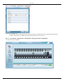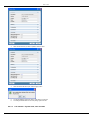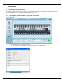
1
ViaLiteHD SNMP and web controller module User Guide HRC-1-HB-4 CR3134 23/12/2013 Pulse Power & Measurement Ltd, 65 Shrivenham Hundred Business Park, Watchfield, Swindon, Wiltshire SN68TY, UK Tel +44 (0)1793 784389 Fax +44 (0)1793 784391 Email [email protected] Web www.vialite.com PPM LTD 2013 2 PPM LTD 2013 Instrument Care and Safety Information Please read the whole of this section before using your ViaLiteHD product. It contains important safety information and will enable you to get the most out of your Fibre Optic Link. Electrical Safety The ViaLiteHD rack chassis is a Safety Class 1 product (having metal chassis directly connected to earth via the power supply cable). When operating the equipment note the following precautions: Hazardous voltages exist within the equipment. There are no user serviceable parts inside; the covers should only be removed by a qualified technician. There are no user replaceable fuses in the rack chassis mounted equipment. Replacement should only be carried out by a PPM technician. The rack chassis earth stud SHOULD be connected to the safety earth. When using a 2 pin power supply cable the rack chassis earth stud MUST be connected to the safety earth. The ViaLiteHD Power Supply Modules do not have an isolating switch on the mains voltage inlet. For this reason, the ViaLiteHD Rack Chassis must be installed within easy reach of a clearly labelled dual pole mains isolation switch, which supplies the equipment. ESD Precautions The ViaLiteHD RF Fibre Optic Link is equipped with high frequency active electronics, without the correct handing they will be susceptible to damage. Precautions for handling electro-static sensitive devices should be observed when handling all ViaLiteHD modules. Technicians should ensure that they use effective personal grounding (i.e. ESD wrist strap etc.) when servicing the equipment. Any equipment or tools used should be grounded to prevent static charge build-up. Good practice should be observed at all times for reference see relevant standards. EN 61340-5-1, “Protection of Electronic Devices from Electrostatic Phenomena – General Requirements” Optical Safety The ViaLiteHD RF Fibre Optic Transmitters, Dual Transmitters and Transceivers contain optical sources (usually laser diodes) operating at nominal wavelengths of 1270nm to 1610nm. These devices are rated as EN60825-1:2007 as CLASS 1 radiation emitting devices. A class 1 laser is safe under all conditions of normal use. When operating the equipment note the following precautions: Never look into the end of an optical fibre directly or by reflection either with the naked eye or through an optical instrument. Never leave equipment with radiating bare fibres – always cap the connectors. Do not remove equipment external covers when operating. 3 PPM LTD 2013 Table of contents 1 INTRODUCTION................................................................................................................................................................................. 6 1.1 Internal architecture 6 1.2 Typical deployment 7 1.3 Care of fibre optic connectors 7 1.4 ViaLiteHD and ViaLite Classic compatibility 7 1.4.1 ViaLiteHD and ViaLite classic compatibility, Ethernet copper RJ45 ports 7 1.4.2 ViaLiteHD and ViaLite classic compatibility, Ethernet optical ports 8 2 VIALITEHD SPECIAL HARDWARE AND SOFTWARE FEATURES ................................................................................................... 9 2.1 Plug and play, default set up 9 2.2 Web based graphical user interface 9 2.3 System robustness 9 2.4 SNMP functionality 9 2.5 Slot auto configuration 9 2.6 System report 9 2.7 FTP download of new software image for SNMP and web controller 9 2.8 Real time clock 10 2.9 Non volatile event history log 10 2.10 Summary alarm relay 10 2.11 On board fast Ethernet switch 10 2.12 On board temperature sensor 10 2.13 GPS mode operation 10 2.13.1 GPS transmitter mode operation 10 2.13.2 GPS receiver mode operation, units equipped with GPS load simulator 10 2.14 Use definable name fields for both individual modules and rack chassis 11 3 SNMP AND WEB CONTROLLER MODULE, PHYSICAL INTERFACES........................................................................................... 12 3.1 Module operation, 7HP standard plug-in module 12 3.2 Fibre optic cable & connectors 13 3.2.1 Connector and cable types 13 3.2.2 Connecting and disconnecting 13 3.2.3 Cleaning optical connectors, cleaning before every use 13 3.2.4 Cleaning optical connectors, high levels of contamination 13 3.2.4.1 FC/APC .......................................................................................................................................... 13 3.2.4.2 SC/APC .......................................................................................................................................... 14 3.2.5 Minimum Bend Radius 14 3.3 Front panel 15 3.3.1 Front Panel Indicators, plug in modules 15 3.3.2 RJ45 Indicators, plug in modules 15 3.3.3 Front panel craft port and reset switch 15 3.4 Rear panel 16 3.4.1 Rear panel, connecting two SNMP and web controller via the fibre ports 16 4 SETTING UP THE SNMP AND WEB CONTROLLER MODULE ....................................................................................................... 17 4.1 Connecting the Module 17 4.2 Setting the IP address and serial interface 17 4.3 Configuring rack chassis slot positions 20 4.4 Setting SNMP protocol communities names 20 5 CONNECTING TO THE SNMP AND WEB CONTROLLER............................................................................................................... 23 5.1 Computer software environment 23 5.2 Computer IP configuration 23 5.3 User access levels and passwords 25 5.4 Setting user access passwords 26 5.5 Other telnet commands 30 6 USING THE WEB CONTROL INTERFACE ...................................................................................................................................... 35 6.1 Box control conventions 35 6.2 Opening the web the graphical user interface with a web browser 35 6.3 Graphical user interface, introduction screen 37 6.4 Top bar 37 6.5 Left side bar 37 6.5.1 Left side bar – System view 37 6.5.1.1 Left side bar – System view, properties .......................................................................................... 38 6.5.1.2 Left side bar – System view, properties, changing contact, name or location .................................. 38 6.5.1.3 Left side bar – System view, inventory ............................................................................................ 40 6.5.1.4 Left side bar – System view, configuration ...................................................................................... 41 6.5.1.5 Left side bar – System view, configuration, changing slot auto configuration .................................. 41 6.5.1.6 Left side bar – System view, environment ....................................................................................... 44 6.5.1.7 Left side bar – System view, thresholds .......................................................................................... 44 6.5.1.8 Left side bar – System view, thresholds, changing thresholds......................................................... 45 6.5.1.9 Left side bar – System view, time and date ..................................................................................... 46 6.5.1.10 Left side bar – System view, time and date, changing the time or date ........................................... 47 6.5.1.11 Left side bar – System view, commands ......................................................................................... 50 6.5.1.12 Left side bar – System view, commands, soft resetting the SNMP module ..................................... 50 6.5.1.13 Left side bar – System view, commands, clearing event history ...................................................... 52 6.5.2 Left side bar – Management 53 6.5.2.1 Left side bar – Management, adding a trap ..................................................................................... 54 4 PPM LTD 2013 6.5.2.2 Left side bar – Management, deleting a trap ................................................................................... 55 Left side bar – System report 56 6.5.3.1 Left side bar – System report, format, header ................................................................................. 56 6.5.3.2 Left side bar – System report, format, system data ......................................................................... 56 6.5.3.3 Left side bar – System report, format, module table ........................................................................ 57 6.5.3.4 Left side bar – System report, format, module data ......................................................................... 57 6.5.3.5 Left side bar – System report, generating a system report .............................................................. 58 6.5.3.6 Left side bar – Event report, format, header .................................................................................... 60 6.5.3.7 Left side bar – Event report, format, events table ............................................................................ 60 6.5.3.8 Left side bar – System report, generating a Event report ................................................................ 61 6.5.4 Left side bar – Software update 62 6.5.4.1 Left side bar – Software update – how to load a new update .......................................................... 63 Bottom event window 65 6.6.1 Bottom event window, sorting events 66 6.6.2 Bottom event window, event severity 66 Central rack chassis graphical interface window 68 6.5.3 6.6 6.7 7 SLOT WINDOWS.............................................................................................................................................................................. 69 7.1 Slot windows general information 69 7.1.1 Slot windows general information, opening the slot window 69 7.2 Slot windows for TX type 71 7.2.1 Slot window for TX type, monitoring 71 7.2.1.1 Slot window for TX type, monitoring, note on TX AGC .................................................................... 72 7.2.2 Slot window for TX type, control 72 7.2.2.1 Slot window for TX type, control, gain control priorities ................................................................... 72 7.2.2.2 Slot window for TX type, control, enabling and disabling the laser .................................................. 73 7.2.2.3 Slot window for TX type, control, turning ON and OFF FSK ............................................................ 75 7.2.2.4 Slot window for TX type, control, turning on SGC and setting the soft gain ..................................... 77 7.2.2.5 Slot window for TX type, control, turning on AGC and setting the AGC target ................................. 80 7.2.2.6 Slot window for TX type, control, calculating AGC target level ........................................................ 82 7.2.2.7 Slot window for TX type, control, enabling and disabling GPS mode............................................... 83 7.2.3 Slot window for TX type, advanced 85 7.3 Slot windows for RX type 85 7.3.1 Slot window for RX type, monitoring 86 7.3.1.1 Slot window for RX type, monitoring, note on RX AGC modes ........................................................ 86 7.3.2 Slot window for RX type, control 87 7.3.2.1 Slot window for RX type, control, gain control priorities ................................................................... 87 7.3.2.2 Slot window for RX type, control, turning on SGC and setting the soft gain ..................................... 87 7.3.2.3 Slot window for RX type, control, turning on AGC and setting the AGC target................................. 90 7.3.2.4 Slot window for RX type, control, calculating AGC target level, RF mode ........................................ 93 7.3.2.5 Slot window for RX type, control, calculating AGC target level, RLL mode ...................................... 93 7.3.2.6 Slot window for RX type, control, turning ON and OFF FSK ............................................................ 93 7.3.2.7 Slot window for RX type, control, enabling and disabling GPS mode .............................................. 95 7.3.3 Slot window for RX type, advanced 97 Slot windows for LNB type 99 7.3.4 Slot windows for LNB type, LNB 99 7.3.4.1 Slot windows for LNB type, LNB, changing mode ......................................................................... 100 7.4 Slot windows for RF switches type 102 7.4.1 Slot windows for RF switches type, monitoring 103 7.4.2 Slot windows for RF switches type, control 103 7.4.2.1 Slot windows for switches type, change mode .............................................................................. 104 7.5 Slot windows for Splitter type 106 7.6 Slot windows for Frequency source type 106 7.7 Slot windows for Redundancy load type 107 7.8 Slot windows for Diplexer source type 107 7.9 Slot windows for Amplifier type 108 7.9.1 Slot window for Amplifier type, monitoring 108 7.9.2 Slot window for Amplifier type, control 109 7.9.2.1 Slot windows for Amplifier type, alarm threshold example ............................................................. 109 7.9.2.2 Slot windows for Amplifier type, change AGC mode ..................................................................... 110 7.9.2.3 Slot windows for Amplifier type, change control values ................................................................. 112 7.9.3 Slot window for Amplifier type, advanced 116 8 SYSTEM INTEGRATION ................................................................................................................................................................ 117 8.1 Initial set up equipment 117 8.2 Site requirements 117 8.3 Other considerations, RJ45 interconnection 117 8.4 Accessing ViaLite HD rack via MIB 117 9 MECHANICAL DIMENSIONS ......................................................................................................................................................... 118 10 PART NUMBERING ........................................................................................................................................................................ 119 11 TECHNICAL SPECIFICATIONS ..................................................................................................................................................... 120 12 MAINTENANCE AND FAULT-FINDING GUIDE .............................................................................................................................. 121 13 GLOSSARY .................................................................................................................................................................................... 122 14 PRODUCT WARRANTY ................................................................................................................................................................. 123 15 FCC APPROVAL ............................................................................................................................................................................ 124 5 PPM LTD 2013 1 Introduction The ViaLiteHD SNMP and Web controller module is used to manage ViaLiteHD equipment, both monitoring and controlling modules. It offers multiple switched 10/100 BaseT copper RJ45 Ethernet interfaces at front and rear and may optionally have a rear 100 BaseF optical interface. It sequentially polls all connected modules to monitor status and send commands. The on board PowerPC runs SNMP firmware that is responsible for monitor, control and updating of the connected module database. It also provides an interface to SNMP manager entities. The SNMP firmware provides an interface to the GUI Java applet, the GUI provides a web based graphic user interface which is displayed on your PC. The module also provides a single dry contact relay accessible via the rack chassis connector. 1.1 Internal architecture Functional Block Optionally fitted function block Key features are: The Main CPU is an PowerPC running at 133MHz The DC input power feed (+12 volts) is protected by a set resetable fuse, which will only open if subject to fault currents. The internal 3.3V is generated by a switch mode power converter running at approximately 320kHz The internal 5V is generated by a switch mode power converter running at approximately 1MHz Other internal voltages are generated from low drop out linear regulators The faster ethernet switch has an external clock of 25MHz and an internal clock of 125MHz The fibre transceiver is low power class 1 and safe under all normal operating conditions The Real time controller has a calendar accurate to 2099 and is clocked at 32kHz The Real time clock is backed up with a super capacitor that has a typical hold up time of more than 10 days The temperature sensor reports the board temperature A single dry contact relay accessible via the rack chassis connector 6 PPM LTD 2013 1.2 Typical deployment The SNMP and Web controller module is typically deployed as part of a 3U rack chassis based equipment solution. It can however be fitted in a range of other equipment. When fitted in an HRK3 rack chassis it must be fitted in slot 14, this is the only slot to have communication with all other slots. 1.3 Care of fibre optic connectors When the fibre optic cables are not connected, it is essential that the cable and equipment connectors are protected by the Dust Caps provided with the system. Failure to do so may result in damage to the fibre ends, which are critical to the system performance. Please refer to section 3.2 for fibre optic cable handling details. 1.4 ViaLiteHD and ViaLite Classic compatibility The ViaLiteHD SNMP and Web controller module will not control or monitor ViaLite Classic equipment. Its 10/100 BaseT copper RJ45 interface may be attached to ViaLite Classic equipment to provide a switching function. The 100 BaseF optical interface may be connected to ViaLite Classic Ethernet 100Mb/s Optical Transceiver 1.4.1 ViaLiteHD and ViaLite classic compatibility, Ethernet copper RJ45 ports ViaLite Classic SNMP Ethernet 100BT ViaLiteHD Ethernet 1000BT SNMP Ethernet 1000BT Family Function 10 BaseT ViaLite Classic SNMP Ethernet 100BT Ethernet 1000BT 100 Base T 10/100/1000 Base T, switchable SNMP Ethernet 1000BT 10/100 Base T, switchable 10/100/1000 Base T, switchable ViaLiteHD 7 Interface type PPM LTD 2013 1.4.2 ViaLiteHD and ViaLite classic compatibility, Ethernet optical ports ViaLite Classic SNMP Ethernet 100BT ViaLiteHD Ethernet 1000BT SNMP Ethernet 1000BT Family Function No fibre interface ViaLite Classic SNMP Ethernet 100BT Ethernet 1000BT 100Base F 1000 Base F ViaLiteHD SNMP Ethernet 1000BT 100Base F 1000 Base F 8 Interface type PPM LTD 2013 2 ViaLiteHD special hardware and software features When using the SNMP and web controller the ViaLiteHD product family make a number of special software and hardware features available to its users. 2.1 Plug and play, default set up The SNMP and web controller module comes full programmed and configured, it is ready to work. You should check both with your network administrator that this address is valid for your LAN and you are able to access it from your computer. Below are the factory default set ups. Default serial port PASSWORD Default FTP PASSWORD: web4270 web4270 Default web GUI address: Default web GUI: 10.0.0.104 LOGIN: + PASSWORD: Default SNMP GET community: Default SNMP SET community: public private use http://10.0.0.104 in your web browser see section 5.3 for other access levels The module maybe reprogrammed, if desired. Full details are given in this handbook in sections 4 and 5. Details are also given in section 5.2 on how to configure your computer. 2.2 Web based graphical user interface The module provides a graphical user interface (GUI) Java applet, the GUI provides a web based interface which is displayed on your PC. The GUI will run on a java enabled web browser and allows you to control and monitor the rack chassis. The GUI is password protected; it has three different levels of access. The passwords for different access levels can be set by you see section 5.3. 2.3 System robustness The ViaLiteHD rack chassis does not require that the SNMP card is either fitted or running to provide full analogue functionality. All modules fitted in the rack chassis can run independently, once configured. 2.4 SNMP functionality The module is able to support SNMP functionality and is supplied with a MIB. 2.5 Slot auto configuration The set up of every module in the rack chassis is stored not only in the module, but it is also stored on board the SNMP and web controller. This allows the controller to remember the configuration of every module in the rack chassis. If the “Auto slot config” is ENABLED the following will happen: All module set up data is stored on the SNMP and web controller when the module is recognised. When a module is removed the SNMP and web controller will remember what type of module was in each rack chassis position. When a new module is inserted into a vacant slot the SNMP and web controller will compares the NEW module type with the FORMER module type (i.e. Transceiver etc...). If this is the same AND “Slot auto config” is ENABLED the controller will up load the FORMER modules configuration to the NEW module. If the NEW module’s type does not match the FORMER module type, no changes will be made to the NEW module If the “Auto slot config” is DISABLED the following will happen: The controller will make no changes, it will however store the NEW module configuration if you wish to enable this feature later. Auto configuration will take a minimum of two rack chassis polling cycles (approximately 15 seconds) to be effective. Auto slot configuration settings will be preserved during a system reset. 2.6 System report This is a tool that allows you to run a report on the rack chassis and save it as an HTML file see section 6.5.3 for more details. 2.7 FTP download of new software image for SNMP and web controller This allows you to update the SNMP and web controller software via FTP. The software update will load a single object containing the operational firmware, graphical user interface (GUI) and management interface browser (MIB). For more details see section 6.5.4.1. 9 PPM LTD 2013 2.8 Real time clock The SNMP and web controller is equipped with a real time clock. This will continue to run after power is removed from the board. It has a built in calendar with leap year correction, up to 2099 and is back up with a super capacitor, which should give at least 10 days of hold up between charges.. 2.9 Non volatile event history log A history of the last 128 events is stored in non volatile memory on the SNMP and web controller. Each event has an index number. This number will increment with each new event. The index number is only reset (to 1) when the event log is cleared. Only the last 128 events are stored, earlier events are erased. See section 6.6 for more details. 2.10 Summary alarm relay The SNMP and web controller provides a summary alarm relay. The module has a volt free 3-pin connection; this is available on the rack chassis connector. The three connections are Normally Open (NO), Common (COM) and Normally Closed (NC). Condition 1 - Power applied to rack chassis, no alarms (i.e. normal condition) Pin NO is open circuit Pin NC is connected to COM Condition 2 - Power removed from rack chassis and/or one or more module alarms (i.e. Alarm condition) Pin NO is connected to COM Pin NC is open circuit 2.11 On board fast Ethernet switch The SNMP and web controller is equipped with a managed on board fast ethernet switch. This supports three copper 10/100 BaseT Ethernet ports and the one optional 100BaseF. All the copper ports auto negotiate and are rate switchable. Pin 1 2 3 4 5 6 7 8 SNMP controller function Ethernet TX+ Ethernet TXEthernet RX+ Not Used Not Used Ethernet RXNot Used Not Used Direction Output Output Input NA NA Input NA NA Comment IP/LAN communication IP/LAN communication IP/LAN communication Terminated on board Terminated on board IP/LAN communication Terminated on board Terminated on board The fibre port must be correctly physically connected (RX to TX) with a suitable 100BaseF transceiver to function correctly. The optical and copper ports may be used to provide connectivity to other SNMP and web controllers and peripheral customer equipment. 2.12 On board temperature sensor The module is equipped with an on board temperature sensor that reports the temperature of the SNMP and web controller module. 2.13 GPS mode operation ViaLiteHD offers a range of modules that can support GPS band signals. It also offers software to mimic the operation of copper connected GPS units. Special GPS band units are equipped with hardware that can provide special GPS functions. They will mimic the operation of an active GPS amplifier through the fibre optic link, allowing alarm status on the remote GPS antenna and LNA to be reported. 2.13.1 GPS transmitter mode operation Under normal no fault condition a GPS TX FOL will operate in an identical fashion to all other ViaLiteHD modules. However the transmitter is equipped with additional hardware that detects the DC current flowing from GPS transmitter RF input, to the active GPS antenna. If the current sunk by the active antenna falls below an alarm threshold (i.e. in the case of the LNA failing or not being connected). The unit will generate an internal alarm. With GPS mode enabled, the transmitter laser will turn off. This will generate an alarm in the connected receiver module, as the connected unit will have a received light level alarm (RLL). The GPS mode can only be ENABLED and DISABLED when the unit is under software control. Modules will be delivered with GPS mode ENABLE. 2.13.2 GPS receiver mode operation, units equipped with GPS load simulator Under normal no fault condition a GPS RX FOL operates very similarly to a normal ViaLiteHD FOL. With GPS mode enabled, in no fault condition it presents a DC load at its RF output to mimic a connected GPS antenna. 10 PPM LTD 2013 When the unit is in a fault condition; either by way of an internal fault, or due to low received light levels from the connected transmitter, it will disable the current sink. For most GPS receivers this will provide a basic alarm function. Modules will be delivered with GPS mode ENABLE. If GPS mode is disabled the DC load will be open circuit in both alarm and non-alarm modes. The GPS mode can only be ENABLED and DISABLED when the unit is under software control. 2.14 Use definable name fields for both individual modules and rack chassis The rack chassis has two USER definable fields (NAME and LOCATION) that may be used to store text information. Each field maybe up to 30 characters in length, this data is stored in the non volatile memory of the SNMP and web controller. More details are given in section 6.5.1.1. Each module position has one USER definable field (NAME) that may be used to store text information on the rack chassis slots. This maybe up to 32 characters in length, this data is stored in the non volatile memory of the SNMP and web controller. The text stored is associated with slot position and will not change if the slot module is changed. 11 PPM LTD 2013 3 SNMP and Web controller module, physical interfaces This section describes the connections between your ViaLiteHD Modules and the SNMP and Web controller module. There is no need to install any interface cables between SNMP and Web controller module and connected modules, as these are all connected via the rack chassis backplane. Please read fully all relevant documents for information on installing your ViaLiteHD equipment before commissioning your system. 3.1 Module operation, 7HP standard plug-in module All ViaLiteHD plug-in modules are hot-swappable, so it is not necessary to power-down the rack chassis before inserting a module. All optical and ethernet connectors are retained by the module. So it is necessary to either disconnect any cables or have a sufficiently long service loop. To install a 7HP Standard module The protective covers on the connectors may be left in place. Push the release button of the module handle down and simultaneously pull the top of the handle forwards. Align the module upright and perpendicular to the front face of the rack chassis so that the PCB slides into the “crow’s feet” card guides top and bottom. Gently push the module down its guide, applying pressure via the handle, you may also apply pressure between the LED and craft port. As the module is fully mated the top of the handle should snap back and lock in position. The pawls of the handle should be fully engaged in the matching slots. If power is applied to the rack chassis the module power LED should light as soon as the module is fully inserted Remove protective covers and connect any interface cables To remove a 7HP Standard module Disconnect any cables if necessary Push the release button of the module handle down and simultaneously pull the top of the handle forwards. Apply pressure via the handle and gently withdraw the module from the rack chassis. 12 PPM LTD 2013 3.2 Fibre optic cable & connectors 3.2.1 Connector and cable types All ViaLiteHD SNMP and Web controller module uses singlemode (9µm/125µm) cable terminated in a range of optical connectors detailed below. Cross-site fibre optic cables are available from PPM as either standard patch leads or heavy-duty multicore cables. Warning! Angle polished (APC) and standard (PC) connector must not be confused. The two connector-types are not interchangeable and mating one with the other will damage both the cable and the module connectors. Warning! The specification of optical connector is critical to the performance of the complete fibre optic link. System performance can only be guaranteed with fibre optic cables and connectors supplied by PPM. When FC/APC connectors are specified they must be “narrow key width” 3.2.2 Connecting and disconnecting Before connecting optical fibres to the module or to each other, ensure that the mating connectors are clean (see below). 3.2.3 Cleaning optical connectors, cleaning before every use Optical connectors MUST be cleaned before use, even where they have been protected with dust caps.. Most performance issues are due to dirty fibres. - Peel the plastic cover from an unused “N” cleaning pad. - Hold the connector between your thumb and forefinger Clean the connector using firm pressure by swiping in a pendulum motion through each segment of the “N” shape, following the diagram - Do not swipe over the same space twice. For more details please read the cleaning instruction which accompanies the connector cleaning kit. Details can also be found on the CD supplied with your equipment. 3.2.4 Cleaning optical connectors, high levels of contamination If there are performance issues that are not resolved by basic cleaning in section 3.2.3, then the following procedure should be used. If the level of contamination is high it will be necessary to repeat this procedure. Cleaning items required Lint free fibre cleaning tissues and/or cleaning sticks(normal cosmetic tissues produce dust and are not acceptable). Reagent grade Iso Propyl Alcohol. Air duster or filtered compressed air line. Cable Connector Cleaning Dampen a patch of cleaning tissue with IPA and clean all surfaces of the plug ferrule. Using a dry cleaning tissue, dry the ferrule and clean the end face. Using the air duster, blow away any residue from the end of the connector. Module Female Receptacle Cleaning (only recommended if problems are being experienced) Either use an optical cleaning stick or twist a cleaning tissue to form a stiff probe, then moisten with IPA. Gently push the probe into the receptacle and twist around several times to dislodge any dirt. Repeat the above process with a dry tissue. Using the air duster, blow away any residue from the receptacle. Important Notes IPA is flammable. Follow appropriate precautions / local guidelines when handling and storing. IPA can be harmful if spilt on skin. Use appropriate protection when handling. It should only be necessary to clean the female receptacles on the modules if problems are being experienced. Never inspect an optical fibre or connector with the naked eye or an instrument unless you are convinced that there is no optical radiation being emitted by the fibre. Remove all power sources to all modules, and completely disconnect the optical fibres. 3.2.4.1 FC/APC All PPM FC connectorised modules use FC/APC (narrow key). Clean the plug before inserting see section 3.2.3. 13 PPM LTD 2013 To connect FC/APC optical connectors: Remove the dustcaps and align the white ceramic centre ferrule on the cable connector with the mating receptacle. There is a key (lug) on the side of the ferrule, which must match the keyway (gap) in the receptacle shroud. When they are aligned, gently push the plug home. Finger tighten the knurled collet nut onto the threaded receptacle. To disconnect: Using fingers fully unscrew the knurled collet nut, gently withdraw the connector. Replace the dustcaps on both the receptacle and the cable plug. Warning! It is possible to tighten the knurled collet without aligning the lug and gap. This will result in poor light transmission. Check that the lug and gap are aligned before tightening the knurled collet Only connect FC/APC cable to FC/APC modules 3.2.4.2 Locate connector key Align key and keyway SC/APC All PPM SC connectorised modules use SC/APC. Clean the plug before inserting see section 3.2.3. To connect SC/APC optical connectors:1. Remove the plug protective cover. 2. Align the connector keyway slot in the adaptor to the key of the plug. 3. Gently push the plug into the adapter until a click is heard and the connector locks. To disconnect:4. grip the body of the plug and gently pull the plug from the adaptor, replace the protective cover. Only connect SC/APC cable to SC/APC. 3.2.5 Minimum Bend Radius Because the optical fibre is made of glass, it is important not to subject it to excessive stress. For this reason, each type of cable has a minimum bend radius (MBR) specification, beyond which the cable cannot be bent without permanent damage occurring. Minimum Bend Radius of Fibre Optic Cable fitted to OEM modules is 50mm MBR specifications for PPM fibre are given in the ViaLite Classic and ViaLiteHD System Handbook Lxx-HB and Hxx-HB. 14 PPM LTD 2013 3.3 Front panel 3.3.1 Front Panel Indicators, plug in modules Each plug-in module has three front panel LEDs for indication of the state of the module. The following table shows the operation of the front panel LEDs which are dependent on module type. LED1 Colour SNMP and Web controller GREEN Normal RED Alarm No light No power GREEN Rear RJ45 port link established No light Rear RJ45 port unconnected GREEN Rear Fibre port link established No light Rear Fibre port unconnected LED1 LED2 LED3 LED2 LED3 SNMP 3.3.2 RJ45 Indicators, plug in modules Each plug-in module has one front and two rear RJ45 connectors. Each has build in LED indicators to show the status of that connection. All RJ45 (and optical) ethernet port connections are connected to an internal ethernet switch. Link LED Colour SNMP and Web controller AMBER or FLASHING No light Link sending/receiving data GREEN Link established No light Unconnected Activity LED No data Link LED Activity LED 3.3.3 Front panel craft port and reset switch Each SNMP and Web controller module is fitted with a craft port, this is used for low level set up and configuration. The craft port uses a Firewire, 6 circuit connector (IEE1394). The module is supplied with a Firewire to 9 way D type cable that can be used for configuration (ppm part number 73706). Craft Port This can be ordered separately, if spares or replacements are required. The hard reset switch is accessible via a small hole behind the handle. Under all normal operating circumstances it should not be required. Actuating the hard reset will cause the module to reboot. Reset Switch SNMP 15 PPM LTD 2013 3.4 Rear panel The rear panel provides interconnections for the rack chassis connector and the rear mounted RJ45 and optional fibre connectors. The optional fibre connectors maybe SC/APC (illustrated) or FC/APC. All RJ45 (and optical) ethernet port connections are connected to an internal ethernet switch. 3.4.1 Rear panel, connecting two SNMP and web controller via the fibre ports When connecting the fibre ports of an SNMP and web controller either to another SNMP and web controller (or to a 100 BaseF fibre transceiver). It is necessary to correctly connected the ports as they will not auto negotiate. 16 PPM LTD 2013 4 Setting up the SNMP and Web controller module Your SNMP and web module is delivered fully configured, see section 2.1. configurations 4.1 Below are details of how to change from these default Connecting the Module Connect the module to the power source and ethernet cables. Optionally you may also connect the module to fibre optic cables as described in section 3.3.3 and connect the dry contact relay (via rack chassis connector). All signals must remain within acceptable limits, see technical specifications in section 11. 4.2 Setting the IP address and serial interface The module needs to be set up before connecting to the network. Computer with serial port and terminal program is needed. Screenshots in this manual relate to the Windows HyperTerminal but any other terminal can be used. 1. Connect the module to the serial port using programming cable 2. Open HyperTerminal (or another equivalent terminal) and create a new connection by choosing File | New Connection 3. Choose Connecting Using and select the serial port VialiteHD rack is connected to. 4. Set the serial port properties to 9600 bps, 8 data bits, 1 stop bit, no parity, no flow control. 17 PPM LTD 2013 5. Click Ok button, terminal now should be ready to work. Open the previously set-up connection and power up the ViaLiteHD rack chassis. The screen should look like in the picture below. 6. If you do not press any key software will operate normally (see screenshot below) 7. If key has been pressed configuration mode is active now. To enter the mode type-in the password. Default password is “web4270”, but it could be changed at this stage If correct password has been entered, main menu appears on the screen. It consists of four options. 18 PPM LTD 2013 8. Display current settings Option displays current IP and FTP settings 9. IP setup menu IP address of the unit, netmask and default gateway can be set. Currently set values are in the brackets. Shall the value remain unchanged, just press Enter. After setting-up the parameters press C if values are correct or M to modify the setting. 10. Software menu This menu allows to download new software version and to set SNMP communities. By default “public” is community name for Read only operations, “private” for Read/Write operations. If software upgrade is not required, keep FTP settings unchanged by pressing ENTER and choose 2 to select Run (otherwise the unit will boot in the serial configuration mode) – standard running mode of operation. 19 PPM LTD 2013 Note that software upgrade requires network connection and cannot be done using serial port. Serial port is used only to set right parameters. File to download has to be accessible via FTP protocol. Upgrade can be done from GUI level, which is in most cases the most convenient way. Note that downloading of incorrect file can prevent the unit from running and will require a factory upgrade. 11. In order to upgrade the software, set the FTP server name, user name and password as well as name of the software file. Then choose 1 to download the new software version. The screen should look like this: After the download has finished, go to the Software menu and choose 2 to run the software (keep pressing ENTER to keep current values of other parameters). 12. Save and Exit Use this option to save the changes done in the process 4.3 Configuring rack chassis slot positions The SNMP and web controller is able to automatically recognise the type of module fitted in each slot. This allows it to use the correct type of graphic for the front panel representation and present an appropriate control interface. The only module that is not recognised by the SNMP and web controller is the redundancy load module, this will just show as a blank slot. In the unlikely event that the modules fitted in your rack chassis post date the software load on your SNMP card, it will present a default graphic and a control interface that contains the basic module information. 4.4 Setting SNMP protocol communities names Before starting to use SNMP protocol communities name need to be set. Community name is password equivalent for SNMP protocol it sets the access level. There are two communities defined, one is “get community” which allows for read only operations; the “set community” allows both reading and writing to the unit. Following convention default the “get community” name is “public” while “set community” name is “private”. Community names can be changed only using craft port. It is not possible to change them via any network protocol. 20 PPM LTD 2013 1. In order to change settings for SNMP communities open serial configuration menu as previously described and choose option 3 ‘Software menu’ see section 4.2. 2. Using this option you can change SNMP communities names, parameters for software upgrade download and mode of operation (for normal option select 2). 3. Current values are displayed in parenthesis. If they should remain unchanged, just press ‘Enter’ key to confirm current value. In the example below all current values were confirmed hence no modification would be done. 4. In case any modification, it will be necessary press ‘M’, otherwise press ‘C’ to continue. 5. In the example below SNMP communities names were changed (from “public” to “read_only_community” and from “private” to “read_write_community”) while the other parameters remained unchanged. 21 PPM LTD 2013 6. If the mode of operation is ‘Run’ after pressing ‘C’ unit reboots and is ready for normal operation – see screenshot below 22 PPM LTD 2013 5 Connecting to the SNMP and web controller Your SNMP and web module is delivered fully configured, see section 2.1. configurations 5.1 Below are details of how to change from these default Computer software environment It is necessary to ensure that your connected computer is correctly configured. Firstly ensure that your PC meets the minimum requirements, it must have: 1. Windows XP, service pack 2 or later 2. Microsoft Internet Explorer 8.0 or later 3. Java Plug-in 1.6.0 or later 5.2 Computer IP configuration Physically connect the ethernet port of your computer either directly the SNMP and web controllers front or rear panel ethernet ports; or to a network that this unit is connected to via a router or switch. Ensure that your PC has a valid IP address issued by the Dynamic Host Configuration Protocol (DHCP) If your computer is running stand alone you may need to configure its IP address manually Open up control panel; and select “Network Connection” and double click Select “local area connection” click right and select properties 23 PPM LTD 2013 Select Internet Protocol (TC/IP) and click on properties Select the option “Use the following IP address” 24 PPM LTD 2013 Now enter a compatible IP address and subnet gateway, you may need you network administrator to advise you of these The IP address should be in the same range as that used for the IP of the SNMP and web controller module You should now be able to connect 5.3 User access levels and passwords There are three levels of user access allowed on the GUI, these are: Access Level USER NAME Description Guest Guest can read all parameters except advanced, cannot modify configuration or execute any commands Admin Admin can read all parameters except advanced, can modify configurations and execute commands Tech Technician can read and modify everything, all command available Each access level has a preset default password, these passwords are: Access Level USER NAME Default PASSWORD Guest Guest guest Admin Admin admin Tech Technician tech These the LOGIN names cannot be changed, but the PASSWORDS may, see the following section Note: The USER NAMES and PASSWORDs for web access are case sensitive 25 PPM LTD 2013 5.4 Setting user access passwords To set user access password you must log onto the module using telnet or a similar system 1. Open a windows command prompt 2. Open a telnet session by typing “telnet” 3. You may check all available commands by typing “?”. 4. Open a telnet session by typing “o <IPADDRESS>” in this example “o 10.0.0.101 26 PPM LTD 2013 5. You will be prompted for the password this is the same us used or set in section 4.2, by default “web4270” (unless changed), note this password is case sensitive 6. When the correct password is entered the unit will display a command prompt “ViaLiteHD” 7. There are three user levels Guest, Admin and Technician. To change user access passwords. You may check all available commands by typing “?”. You can check the format of a specific command by typing the command followed by “?”. 27 PPM LTD 2013 8. Now change the passwords as desired using this the set http password command, as shown below. Note these passwords are case sensitive. 9. You may now confirm the passwords using the “show http password command” 28 PPM LTD 2013 10. You should now log off by typing “logoff” and pressing any key when prompted. Failure to logoff and close the telnet session correctly may impact the card functionality. If this happens it may simply be rectified by a hard reset. 11. The telnet session should now be closed, by typing “c” and then “q” 29 PPM LTD 2013 12. You may now resume normal operation and close the command window 5.5 Other telnet commands The Telnet interface maybe used for a number of other actions detailed below To set user access password you must log onto the module using telnet or a similar system 1. Open a windows command prompt 2. Open a telnet session by typing “telnet” 30 PPM LTD 2013 3. Open a telnet session by typing “o <IPADDRESS>” in this example “o 10.0.0.101 4. You will be prompted for the password this is the same us used or set in section 5.3, by default “web4270” (unless changed), note this password is case sensitive 5. When the correct password is entered the unit will display a command prompt “ViaLiteHD” 31 PPM LTD 2013 6. You may check all available commands by typing “?”. 7. The following commands are available detailed below: “show version” (no arguments are required) “show ip” (no arguments are required) 32 PPM LTD 2013 “show http password” (no arguments are required) “set http password” Format required “set http password <access level> <new password>” “reboot” (no arguments are required) 33 PPM LTD 2013 “log off” (no arguments are required) 8. You can check the format of a specific command by typing the command followed by “?” 34 PPM LTD 2013 6 6.1 Using the web control interface Box control conventions All BUTTONS and ICONS can be activated by a single left click Some boxes have arrow icons in the top left of the box, these allow the boxes to be maximised or minimised Many boxes have a hover function. If you hover the point over a module it will display it key information, some boxes with settable parameters will also display their valid range if you hover over them. If information is entered as TEXT, NUMBERS, PULL DOWNS you must hit the windows APPLY button to send this information to the controller. CHANGES SHOULD BE APPLIED INDIVIDUALLY, once implemented the next change should be made. This prevents the possibility of changes overwriting each other or control words being incorrect. 6.2 Opening the web the graphical user interface with a web browser First open a web browser. The web browser must be java enabled and have Java Plug-in 1.6.0 or later loaded, if not you will be prompted to download this. Type in the IP address of the module, into the browser address line, in this case “10.0.0.101” After having typed in the module address you will be prompted for the password Use the USER NAME and PASSWORD that have been set see section 5.3 and 5.4 35 PPM LTD 2013 The graphical user interface web page will now be available. 36 PPM LTD 2013 6.3 Graphical user interface, introduction screen This is the first screen that the web page will open with, it contains all the basic information that you will need 6.4 Top bar IP address Location (this is user definable text and can be entered on the system menu) Name (this is user definable text and can be entered on the system menu) Contact, manufacturer or suppliers contact information (this is user definable text and can be entered on the system menu) Log in name Note: The IP address is the IP address as seen by the computer. This may be different to the IP address of the SNMP controller if you are accessing via an external network. 6.5 Left side bar This bar contains views that may be used to set up and read parameters of the SNMP and Web controller System view – Allow viewing and setting of many controller, power supply and rack chassis parameters Management – Allows trap destination and MIB version to be set and read System report – This provides a summary report of the rack chassis and module information Software update – This allows the SNMP and web controller software to be updated via FTP 6.5.1 Left side bar – System view To open the system view, left click the system icon on the left side bar 37 PPM LTD 2013 6.5.1.1 Left side bar – System view, properties System view - Properties box Description – This preset text described the module function Uptime – This reports the running time of the SNMP and web controller since the last reset Contact - This is USER definable text and can be entered on this screen, it defaults to PPM contact details Name - This is USER definable text (up to 30 characters) and can be entered on this screen, it defaults to “defaultName” Location - This is USER definable text (up to 30 characters) and can be entered on this screen, it defaults to “defaultLocation” Note: Contact, name and location will be preserved during a system reset. 6.5.1.2 Left side bar – System view, properties, changing contact, name or location To change contact, name or location: 1. Left click the SYSTEM icon on the left side bar, this opens the system view box 38 PPM LTD 2013 2. The properties box will already be maximised box 3. 4. Next click the box that you wish to update, enter the text When the text has been input, click the apply button 5. You will be asked to confirm the action, click YES if you are sure 39 PPM LTD 2013 6. 6.5.1.3 The change will now be in effect. Left side bar – System view, inventory System view - Inventory box Product model – This give the basic hardware model number SW version – This gives the version number of the GUI software loaded on the card Hardware revision – This gives the revision number of the SNMP and web controller hardware MAC address – This gives the MAC address of the SNMP and web controller hardware Serial number – This gives the serial number of the SNMP and web controller hardware 40 PPM LTD 2013 6.5.1.4 Left side bar – System view, configuration System view - Configuration box Slot auto config – This is a USER settable option that allows the slot auto configuration option to be turned ON and OFF.By default this feature is switched OFF. Full details of this special software feature are given in section 2.5. 6.5.1.5 Left side bar – System view, configuration, changing slot auto configuration To change the Auto slot configuration: 1. Left click the SYSTEM icon on the left hand bar 41 PPM LTD 2013 2. Click the arrow on the right of the configuration box to maximise this box 3. Select from the pull down menu the desired status for the slot auto configuration 42 PPM LTD 2013 4. After having selected the mode, click on the windows apply button 5. 6. You will be asked to confirm the action, click YES if you are sure The change will take effect on the next polling cycle of the slot 43 PPM LTD 2013 6.5.1.6 Left side bar – System view, environment System view –Environment box Temperature – This reports the temperature measured on the SNMP and web controller card. Note: typically this is 15 - 20 degrees above the rack chassis ambient temperature. High temperature – This reports the high temperature threshold, a reported temperature above the threshold will generate a “system temperature alarm”. The threshold cannot be set in this window. Voltage – This reports the rack chassis backplane voltage High voltage - This reports the high voltage threshold, a reported voltage above the threshold will generate a “system voltage alarm”. The threshold cannot be set in this window. Low voltage - This reports the low voltage threshold, a reported voltage above the threshold will generate a “system voltage alarm”. The threshold cannot be set in this window. PSU1 status – This reports the stats of the power supply in rack chassis slot 15, its status can be NORMAL or FAILURE PSU2 status – This reports the stats of the power supply in rack chassis slot 16, its status can be NORMAL or FAILURE Note. As the PSU is unintelligent a status of FAILURE may be due to a real hardware failure or an unfitted PSU. 6.5.1.7 Left side bar – System view, thresholds 44 PPM LTD 2013 System view – Thresholds High temperature – This is a USER settable threshold, it maybe between 20 and 99, by DEFAULT it is set to 70 degrees centigrade. High voltage - This is a USER settable threshold, it maybe between 12 and 15, by DEFAULT it is set to 13 volts Low voltage - This is a USER settable threshold, it maybe between 9 and 12, by DEFAULT it is set to 11 volts Note: Temperature and voltage thresholds will be preserved during a system reset. 6.5.1.8 Left side bar – System view, thresholds, changing thresholds To change any of the threshold values: 1. Left click the SYSTEM icon on the left hand bar 2. Click the arrow on the right of the thresholds box to maximise this box 45 PPM LTD 2013 3. Next click the box that you wish to update, enter the value 4. When the value has been input, click the apply button 5. 6. You will be asked to confirm the action, click YES if you are sure The change will take effect on the next polling cycle of the slot 6.5.1.9 Left side bar – System view, time and date 46 PPM LTD 2013 System view – Time and date Date – This is a USER settable date, it in the format DD/MM/YY. Time - This is a USER settable time, it in the format HH/MM/SS in a 24 hour format. Note: The unit is equipped with a real time clock, which will preserve time and date in the event of a power outage or short storage period. Note: Time and date will be preserved during a system reset. 6.5.1.10 Left side bar – System view, time and date, changing the time or date To change the time or date: 1. Left click the SYSTEM icon on the left hand bar 47 PPM LTD 2013 2. Click the arrow on the right of the time and date box to maximise this box 3. Next click the box that you wish to update, enter the value 48 PPM LTD 2013 4. When the value has been input, click the apply button 5. 6. You will be asked to confirm the action, click YES if you are sure The change will take effect on the next polling cycle of the slot 49 PPM LTD 2013 6.5.1.11 Left side bar – System view, commands System view – Time and date Reset device – This allows you to perform a soft reset on the SNMP and web controller card, before reset you will be prompted to confirm the action. A reset typically takes about 20 seconds. The reset does not clear the event history. Clear event history - This allows you to clear the event history of the SNMP and web controller card, before clearing you will be prompted to confirm the action. The first event displayed after clearing the event log is “system events cleared”. Note: You cannot clear the event log if there are no other events. 6.5.1.12 Left side bar – System view, commands, soft resetting the SNMP module To perform a soft reset on the SNMP and web controller: 1. Left click the SYSTEM icon on the left hand bar 50 PPM LTD 2013 2. Click the arrow on the right of commands to maximise this box 3. Next click the RESET DEVICE button 4. 5. You will be asked to confirm the action, click YES if you are sure The SNMP and web controller will be reset, it typically takes 30 second to perform this action 51 PPM LTD 2013 6.5.1.13 Left side bar – System view, commands, clearing event history To clear the event history of the SNMP and web controller: 1. Left click the SYSTEM icon on the left hand bar 2. Click the arrow on the right of COMMANDS to maximise this box 52 PPM LTD 2013 3. Next click the CLEAR EVENT HISTORY button 4. 5. You will be asked to confirm the action, click YES if you are sure The first event recorded after this action will be SYSTEM EVENTS CLEARED 6.5.2 Left side bar – Management The management icon allows you to set up to 5 trap destinations. The traps are displayed in the IP address box 53 PPM LTD 2013 The about button maybe used to show the MIB software details System view – Time and date Product – This preset text described the product type Version – This gives the version number of the MIB software loaded on the card Date – This gives the revision date of the MIB software loaded on the card 6.5.2.1 Left side bar – Management, adding a trap To add a trap: 1. Click the Add box, the box below will appear 2. 3. Type in the IP address which you wish to use as a trap destination Click okay, the trap is now set 54 PPM LTD 2013 6.5.2.2 Left side bar – Management, deleting a trap To delete a trap: 1. You can delete trap address by selecting the IP address from the IP address window, it will be highlighted. 2. Then clicking on the Delete button 3. The Trap has now been deleted, repeat the process for any other unwanted traps 55 PPM LTD 2013 6.5.3 Left side bar – System report The system report is a tool that allows you to run either a status report on the modules that are corrected to the same rack chassis as the SNMP and web controller, or to report all the stored events. Both reports are exported as an HTML files. System report Report file name – This displays the file name for the report file Pull down menu – This allows you to choose either a SYSTEM REPORT or an EVENTS REPORT Open report automatically - If this box is CHECKED your web browser will automatically open the report after it is generated The SYSTEM REPORT consists of a number of sections these are detailed in the following sections 6.5.3.1 Left side bar – System report, format, header This contain the report title time and date 6.5.3.2 Left side bar – System report, format, system data This contain all the basic information about the rack chassis SNMP and web controller and power supplies 56 PPM LTD 2013 6.5.3.3 Left side bar – System report, format, module table This contains summary information on all the other modules in the rack chassis 6.5.3.4 Left side bar – System report, format, module data Module data – This contain detail information on each module fitted in the rack chassis, unpopulated slots are not reported. 57 PPM LTD 2013 6.5.3.5 Left side bar – System report, generating a system report To generate the system report 1. Left click the SYSTEM REPORT icon on the left hand bar 2. Click the “…” button on the right of the report file name box 3. 4. 5. 6. Navigate to the directory in which you wish to save the report Type a file name into the “file name” box File type cannot be changed it will always generate an HTML file Then click save 58 PPM LTD 2013 59 PPM LTD 2013 7. Check that SYSTEM REPORT is selected in the pull down menu 8. 9. If you wish your web browser to automatically open the report after it is generated CHECK the “open report automatically” Now click the generate button 6.5.3.6 Left side bar – Event report, format, header This contain the report title time and date 6.5.3.7 Left side bar – Event report, format, events table This contain all the stored event information in a similar format to the GUI 60 PPM LTD 2013 6.5.3.8 Left side bar – System report, generating a Event report To generate the event report 1. Left click the SYSTEM REPORT icon on the left hand bar 2. Click the “…” button on the right of the report file name box 3. 4. 5. 6. Navigate to the directory in which you wish to save the report Type a file name into the “file name” box File type cannot be changed it will always generate an HTML file Then click save 61 PPM LTD 2013 7. Check that EVENT REPORT is selected in the pull down menu, if not select it. 8. 9. If you wish your web browser to automatically open the report after it is generated CHECK the “open report automatically” Now click the generate button 6.5.4 Left side bar – Software update This allows you to update the SNMP and web controller software via FTP. Software – Files box Type – This shows the type of file last uploaded Name – This is the file name last uploaded Size – This is the size of the file last uploaded in bytes 62 PPM LTD 2013 Operation box – Files box File name – This is a USER text field in which the name of the file to be uploaded is stored Download image button – One ALL the download data fields have been correctly entered this is used to START the download Status – This shows the status of the download Progress – This shows the progress of the download Operation box – Files server box FTP IP address – This is a USER field in which the name of the FTP serve is entered User name – This is the user name to access your FTP server Password – This is the password associated user name to access your FTP server 6.5.4.1 Left side bar – Software update – how to load a new update To upload a new software object: 1. 2. 3. Left click the SOFTWARE UPDATE icon on the left hand bar Click the arrow on the right of OPERATION to maximise this box Click the arrow on the right of FILE SERVER to maximise this box 63 PPM LTD 2013 4. 5. 6. 7. 8. Ensure that your FTP server details are correct a. FILE SERVER box – IP ADDRESS b. FILE SERVER box – USER NAME c. FILE SERVER box – PASSWORD Note: You can use software such as FileZilla Server to support this function on a PC Enter the file name of the object that to load into the Operations FILE NAME box, It will be in a format similar to the example. Press the APPLY button at the bottom of the window to apply this file name Recheck all the details. It is possible to corrupt the board if an incorrect image is loaded. This may require a factory reset Press the DOWNLOAD IMAGE button. 9. You will be asked to confirm the action, click YES if you are sure 10. 11. 12. 13. 14. 15. You will see the upload start, progress and complete. Typically it will take about 2 minutes but is very dependent on your network When the status windows says READY the new software is loaded To restart the GUI you MUST close the close ALL the web browser windows in which it is running Open a new web browser window You may confirm the version by clicking the left hand menu SYSTEM icon and opening the INVENTORY box. 64 PPM LTD 2013 6.6 Bottom event window The ViaLiteHD SNMP and web controller has a window which displays system events. It provides a history of the last 128 events is stored in non volatile memory on the SNMP and web controller. Each event is has an index number, this number is increment with each new event. The GUI is able to provide a visual indication of new events. When a new event occurs, the “event” text at the top of the event box will flash green and black. If you click this to acknowledge the event the text will stop flashing until there is a new event. The last 128 event are stored, each event generates an event index number starting at 1. The index number will increase each time there is a new event, it is not numerically limited. The index number is only reset (to 1) when the event log is cleared. Only the last 128 events are stored, earlier event are erased. The event window can be maximised by clicking the arrows in the top right hand corner of the window. It can be minimised in the same fashion 65 PPM LTD 2013 6.6.1 Bottom event window, sorting events The events can be sorted by any of the event table columns, in both forward and reverse order Index Time and date Uptime Event type Slot Module type Severity The default sort order is by index number To change the sort order Clicking the column heading you wish to use Click it again to toggle between ascending and descending sorting. An up/down arrow is displayed on the heading by which the table is sorted, it indicates the sort direction 6.6.2 Bottom event window, event severity There are a number of levels of event severity these are all colour coded in the event window Major alarm are coded RED Minor alarm are coded YELLOW Normal events are coded GREEN Notify events are coded TURQUOISE The alarm are classified as follows Major alarm – These are typically events that may cause major disruption to operation, depend on deployment these may or may not be critically service effecting. Typical events to trigger this would be low light level at optical receivers (RLL Alarm), card removal or similar. Any major alarm will change the SNMP and web controller LED from green to red. Minor alarms – These are typically event that may degrade performance or warn of impending major alarms, they may effect the quality of service. Typical events would be system temperature alarm, RX AGC alarm, Voltage feed alarm or similar Normal event– These are events that would be expected to happen under normal operation. Typical type of events would be system start up and alarms being cleared. Notify event – These are the type of events that are useful to record as the represent a change in status. A typical type of event would be card insertion. 66 PPM LTD 2013 Following is a list of all the events types and their severity. The severity of the events is dependent on there event type and preset in the software. Alarm description Severity AGC Alarm MINOR AGC Alarm Cleared NORMAL Bias Alarm MINOR Bias Alarm Cleared NORMAL Card Inserted NOTIFY Card Removed MAJOR Current Feed Alarm MINOR Current Feed Alarm Cleared NORMAL Laser Alarm MAJOR Laser Alarm Cleared NORMAL Major Alarm MAJOR Major Alarm Cleared NORMAL Minor Alarm MINOR Minor Alarm Cleared NORMAL Overload Alarm Clear NORMAL Overload Alarm MINOR Power Alarm MINOR Power Alarm Cleared NORMAL PSU Alarm MINOR PSU Normal NORMAL RF Gain Alarm MINOR RF Gain Alarm Cleared NORMAL RF Level Alarm MINOR RF Level Alarm Cleared NORMAL RLL Alarm MAJOR RLL Alarm Cleared NORMAL System Events Cleared NORMAL System Start-up NORMAL System Temperature Alarm MINOR System Temperature Alarm Cleared NORMAL System Voltage Alarm MINOR System Voltage Alarm Cleared NORMAL Temperature Alarm MINOR Temperature Alarm Cleared NORMAL Temperature Clear NORMAL Temperature Overload MINOR VCC Alarm MINOR VCC Alarm Cleared NORMAL Voltage Feed Alarm MINOR Voltage Feed Alarm Cleared NORMAL 67 PPM LTD 2013 6.7 Central rack chassis graphical interface window The central window give a graphical representation of both the modules fitted in the chassis and there status This window has the following features Each modules should be represented in the correct slot Each module should have a graphically correct front panel Each of the modules LEDs should reflect the status of the actual module Each module in slots 1-13 can be hovered over this will display its slot number, part number and type Each module in slots 1-16 is click able, with a single left click, this will bring up o SLOT window for modules in slots 1-13 o A SYSTEMS VIEW window in slot 14, with the PROPERTIES box maximised o A SYSTEMS VIEW window in slots 15 and 16, with the ENVIRONMENT window maximised Note: The text on some modules maybe modified to improve readability Full detail of the operation of the modules and how they can be software controlled is given in the section 7 and its subsections. 68 PPM LTD 2013 7 Slot windows 7.1 Slot windows general information This information is always available in every slots with a module fitted. The only exception is in a slot fitted with a redundancy load module; the redundancy load module has no processor and will show as blank. All modules have a NAME field that maybe used to store USER defined text information of up to 32 characters. More details are given in section 2.14 7.1.1 Slot windows general information, opening the slot window To open any slot window: 1. 2. Left click slot GUI image, this will open the slot window a. Note if you hover over the window you will display the slot number, part number and type The type of window that opens depends on the slot number a. For Slots 1-13 a slot window will be opened 69 PPM LTD 2013 b. For Slot 14 a SYSTEMS VIEW window will open with the PROPERTIES box maximised c. For slots 15 and 16 a SYSTEMS VIEW window will open with the ENVIRONMENT window maximised 70 PPM LTD 2013 7.2 Slot windows for TX type The TX type module will open with the GENERAL box maximised 7.2.1 Slot window for TX type, monitoring Slot window – TX type, monitoring Supply voltage – This is the supply voltage measured at the input to the module, measured in volts Laser power – This is the average optical power output of the laser, measured in decibel milli watts RF gain – This is the electro optic gain of the module measured in decibels Ext. voltage – This is the bias voltage measured at the RF input to the transmitter, measured in volts Laser bias – This is the bias current of the laser diode, measured in milli amps RF power – This is the RF power measured at the input to the laser diode, measured in decibel milli watts Ext. current – This is the average DC current flowing out of the RF input, measured in milli amps 71 PPM LTD 2013 Laser – This is the laser power control loop status, it can be ENABLED (on) or DISABLED (off) MGC status – This is the manual gain control status, it can ON or OFF SGC status – This is the software gain control status, it can ON or OFF FSK status –This is the frequency shift key digital communications channel status, it can be ENABLED (on) or DISABLED (off). AGC status – This is the automatic gain control status, it can be ENABLED (on) or DISABLED (off). GPS status - This shows the status of the GPS mode, it can be ON or OFF. Major alarm –This is the major alarm status, it can be ON (alarm active) or OFF (good). Laser alarm –This is the laser control loop alarm status, it can be ON or OFF. Vcc alarm –This is the (input) voltage alarm status, it can be ON or OFF. Power alarm –This is the laser output power alarm status, it can be ON or OFF. Voltage alarm –This is the external feed voltage alarm status, it can be ON or OFF. Level alarm –This is the RF power level alarm status, it can be ON or OFF. Minor alarm –This is the minor alarm status, it can be ON or OFF. AGC alarm –This is the automatic gain control alarm status, it can be ON or OFF. Bias alarm – This is the laser bias current alarm status, it can be ON or OFF. Current alarm - This is the external feed current alarm status, it can be ON or OFF. Temp alarm – This is the temperature alarm status, it can be ON or OFF. Gain alarm – This is the RF gain alarm status, it can be ON or OFF. 7.2.1.1 Slot window for TX type, monitoring, note on TX AGC When set to operate in AGC mode the TX module can only operate in RF control mode. When operating in RF mode, the TX module will use a slow control loop to set the power at the monitor to the AGC TARGET level. The gain is continuously adjusted and is controlled in 0.5dB steps 7.2.2 Slot window for TX type, control Slot window – TX type, control Gain soft set – This sets the value of the set electro optic gain, measured in decibels Laser – This sets the laser status, it can be ENABLED (on) or DISABLED (off). AGC – This sets the automatic gain control status, it can be ENABLED (on) or DISABLED (off). GPS mode - This sets the GPS emulation status, it can be ENABLED (on) or DISABLED (off). AGC target – This sets the target value for the AGC control loop module, measured in decibel milli watts. FSK – This sets the status of the frequency shift key digital communications channel, it can be ENABLED (on) or DISABLED (off). SGC – This sets the software gain control status, it can be ENABLED (on) or DISABLED (off). 7.2.2.1 Slot window for TX type, control, gain control priorities There are a number of methods by which the gain maybe controlled depending on module type. It is possible to make a number of them active simultaneously. In this case the module firmware will discriminate by order of priority. 72 PPM LTD 2013 Highest Priority Lowest Priority MGC, manual gain control set using module hardware switches, available on rack modules SGC, soft gain control, set via controller AGC, Automatic gain control, set via controller Default gain, Factory pre-set gain The gain set by MGC is not reported through the control interface 7.2.2.2 Slot window for TX type, control, enabling and disabling the laser To change the laser status: 1. Left click slot GUI image, this will open the slot window 2. Maximise the CONTROL box 73 PPM LTD 2013 3. Using the pull down menu change the status of the laser 4. 5. The desired status will now be shown in the box Click the APPLY button 6. 7. 8. You will be asked to confirm the action, click YES if you are sure The change will take effect on the next polling cycle of the slot You can confirm that the change is in effect by opening the MONITORING box 74 PPM LTD 2013 7.2.2.3 Slot window for TX type, control, turning ON and OFF FSK To change the FSK status: 1. Left click slot GUI image, this will open the slot window 2. Maximise the CONTROL box 75 PPM LTD 2013 3. Using the pull down menu change the status of the FSK 4. 5. The desired status will now be shown in the box Click the APPLY button 6. 7. 8. You will be asked to confirm the action, click YES if you are sure The change will take effect on the next polling cycle of the slot You can confirm that the change is in effect by opening the MONITORING box 76 PPM LTD 2013 7.2.2.4 Slot window for TX type, control, turning on SGC and setting the soft gain Note that the SGC settings will ONLY be effective when BOTH the MGC switches are all set in the OFF position (factory default) AND the AGC status is DISABLED To change the SGC: 1. Left click slot GUI image, this will open the slot window 2. Maximise the CONTROL box 77 PPM LTD 2013 3. 4. Check that the AGC status is DISABLED, if not set it to DISABLED using the pull down menu Check that the SGC status is ENABLED, if not set it to ENABLED using the pull down menu 5. 6. You may hover over the GAIN SOFT SET box to determine the valid SGC range Enter the desired value into the GAIN SOFT SET box 78 PPM LTD 2013 7. 8. The desired status will now be shown in the box Click the APPLY button 9. You will be asked to confirm the action, click YES if you are sure 10. The change will take effect on the next polling cycle of the slot 11. You can confirm that the change is in effect by opening the MONITORING box Note: The gain setting is rounded to closest 0.5dB step 79 PPM LTD 2013 7.2.2.5 Slot window for TX type, control, turning on AGC and setting the AGC target Note that the AGC settings will ONLY be effective when the MGC switches are all set in the OFF position (factory default). To change the AGC: 1. Left click slot GUI image, this will open the slot window 2. Maximise the CONTROL box 80 PPM LTD 2013 3. Check that the AGC status is ENABLED, if not set it to ENABLED using the pull down menu 4. 5. You may hover over the AGC TARGET box to determine the valid AGC range Enter the desired value into the AGC TARGET box 81 PPM LTD 2013 6. 7. The desired status will now be shown in the box Click the APPLY button 8. You will be asked to confirm the action, click YES if you are sure 9. The change will take effect on the next polling cycle of the slot 10. You can confirm that the change is in effect by opening the MONITORING box Note: The gain setting is rounded to closest 0.5dB step 7.2.2.6 Slot window for TX type, control, calculating AGC target level The variations in the input level can be compensated by using transmitter AGC control. This can be used for two main purposes, either to fix the average RF output power or to control intermodulation products so that, for example, desired ratio of carrier to intermodulation distortions can be achieved. The RF power is the level measured at the internal power detector and is dependent on the input signal level and gain control. The AGC TARGET LEVEL is level that the module aims to achieve by gain control ahead of the internal detector. It can be set to a desired level so that RF MON will be locked to it with an accuracy of approx. 0.5dB when the AGC loop works normally. To find out the value for AGC TARGET LEVEL when INPUT POWER is known, you may use the equation below AGC TARGET LEVEL = INPUT POWER + RF GAIN – (RF GAIN CAL –RF MON CAL) where RF GAIN is the real time monitor of TX GAIN and RF GAIN CAL and RF MON CAL are the module factory calibration constants stored in the TX Type ADVANCED parameters box. If the gain of the complementary receiver is known you may also relate the AGC TARGET LEVEL to the receiver OUTPUT POWER. AGC TARGET LEVEL = OUTPUT POWER – RF GAIN (RX) – (RF GAIN CAL –RF MON CAL) + 2 x Optical Loss OR OUTPUT POWER = AGC TARGET LEVEL + RF GAIN (RX) + (RF GAIN CAL –RF MON CAL) - 2 x Optical Loss 82 PPM LTD 2013 7.2.2.7 Slot window for TX type, control, enabling and disabling GPS mode Under normal non-fault condition a GPS TX FOL will operate in an identical fashion to all other ViaLiteHD modules. However the transmitter is equipped with additional hardware, this detects the DC current flowing from GPS transmitter RF input to the active GPS antenna. With GPS mode enabled, the transmitter laser will turn off, if the antenna current falls to near zero. Full details are given in your RF modules handbook. To change the GPS mode status: 1. Left click slot GUI image, this will open the slot window 2. Maximise the CONTROL box 83 PPM LTD 2013 3. Check the GPS mode status, choose the desired status using the pull down menu 4. 5. The desired status will now be shown in the box Click the APPLY button 6. 7. 8. You will be asked to confirm the action, click YES if you are sure The change will take effect on the next polling cycle of the slot You can confirm that the change is in effect by opening the MONITORING box 84 PPM LTD 2013 7.2.3 Slot window for TX type, advanced Slot window – TX type, advanced Bias set – This is the factory set laser power control loop DC target voltage, measured in millivolts Power cal – This is the factory optic monitor ADC calibration set point, measured in digital steps. RF mon cal – This is the RF detector calibration, the ratio of internal measured to rear port power in Z0 ohms, measured in decibels Monitor mask – This is a factory setting that can be used to mask some analogue alarms RF gain cal – This is a factory setting that can be used to calculating AGC thresholds, see section 7.2.2.6 Power set – This is the factory set average laser power, measured in decibel milli watts Gain default – This is the factory set default gain for the module, measured in decibels FSK freq set – This is the factory setting for the FSK tone frequency, measured in digital steps. Events mask – This is a factory setting that can be used to mask some digital alarms 7.3 Slot windows for RX type The RX type module will open with the GENERAL box maximised 85 PPM LTD 2013 7.3.1 Slot window for RX type, monitoring Slot window – RX type, monitoring Supply voltage – This is the supply voltage measured at the input to the module, measured in volts RF power – This is the RF power measured at the input to the laser diode, measured in decibel milli watts RLL – Received light level, measured in decibel milli watts. RF gain – This is the electro optic gain of the module measured in decibels. FSK detect - This shows if an FSK low speed digital carrier has been detected, it can ON (carrier present) or OFF (no carrier). MGC status – This is the manual gain control status, it can ON or OFF. SGC status – This is the software gain control status, it can ON or OFF. GPS status - This shows the status of the GPS mode, it can be ON or OFF. FSK status –This is the frequency shift key digital communications channel status, it can be ENABLED (on) or DISABLED (off). AGC status – This is the automatic gain control status, it can be ENABLED (on) or DISABLED (off). AGC mode - This is the automatic gain control mode, it can be OFF or RLL or RF Major alarm –This is the major alarm status, it can be ON (alarm active) or OFF (good). AGC alarm –This is the automatic gain control alarm status, it can be ON (alarm active) or OFF (good). RLL alarm – This is the received light level alarm status, it can be ON (alarm active) or OFF (good). Gain alarm – This is the RF gain alarm status, it can be ON (alarm active) or OFF (good). Minor alarm –This is the minor alarm status, it can be ON (alarm active) or OFF (good). Vcc alarm –This is the (input) voltage alarm status, it can be ON (alarm active) or OFF (good). Level alarm –This is the RF power level alarm status, it can be ON (alarm active) or OFF (good). 7.3.1.1 Slot window for RX type, monitoring, note on RX AGC modes When set to operate in AGC mode the RX module can operate in either RLL or RF control mode When operating in RLL mode, the RX module, will compensate for any optical loss by increasing the modules gain by 2dB of RF gain for each 1dB in reduction in received light level, from default 3mW (4.7dBm) optical output of a ViaLite transmitter. In this mode the AGC TARGET data is not required; any data value set in the AGC TARGET will be ignored. The gain is controlled in 0.5dB steps. When operating in RF mode, the RX module will use a slow control loop to set the power at the monitor to the AGC TARGET level. The gain is continuously adjusted and is controlled in 0.5dB steps 86 PPM LTD 2013 7.3.2 Slot window for RX type, control Slot window – RX type, control Gain soft set – This sets the value of the set electro optic gain, measured in decibels FSK – This sets the status of the frequency shift key digital communications channel, it can be ENABLED (on) or DISABLED (off). SGC – This sets the software gain control status, it can be ENABLED (on) or DISABLED (off). GPS mode –This sets the GPS load status, it can be ENABLED (on) or DISABLED (off). AGC target – This sets the target value for the AGC control loop module, measured in decibel milli watts. AGC – This sets the automatic gain control status, it can be ENABLED (on) or DISABLED (off). AGC mode – This set the mode for the automatic gain, it can be driven by RLL (received light level) or RF (radio frequency) power 7.3.2.1 Slot window for RX type, control, gain control priorities There are a number of methods by which the gain maybe controlled depending on module type. It is possible to make a number of them active simultaneously. In this case the module firmware will discriminate by order of priority. Highest Priority Lowest Priority MGC, manual gain control set using module hardware switches, available on rack modules SGC, soft gain control, set via controller AGC, Automatic gain control, set via controller Default gain, Factory pre-set gain The gain set by MGC is not reported through the control interface 7.3.2.2 Slot window for RX type, control, turning on SGC and setting the soft gain Note that the SGC settings will ONLY be effective when BOTH the MGC switches are all set in the OFF position (factory default) AND the AGC status is DISABLED To change the SGC: 87 PPM LTD 2013 1. Left click slot GUI image, this will open the slot window 2. Maximise the CONTROL box 88 PPM LTD 2013 3. 4. Check that the AGC status is DISABLED, if not set it to DISABLED using the pull down menu Check that the SGC status is ENABLED, if not set it to ENABLED using the pull down menu 5. 6. You may hover over the GAIN SOFT SET box to determine the valid SGC range Enter the desired value into the GAIN SOFT SET box 89 PPM LTD 2013 7. 8. The desired status will now be shown in the box Click the APPLY button 9. You will be asked to confirm the action, click YES if you are sure 10. The change will take effect on the next polling cycle of the slot 11. You can confirm that the change is in effect by opening the MONITORING box Note: The gain setting is rounded to closest 0.5dB step 7.3.2.3 Slot window for RX type, control, turning on AGC and setting the AGC target Note that the AGC settings will ONLY be effective when the MGC switches are all set in the OFF position (factory default). To change the AGC: 90 PPM LTD 2013 1. Left click slot GUI image, this will open the slot window 2. Maximise the CONTROL box 3. 4. Check that the AGC status is ENABLED, if not set it to ENABLED using the pull down menu Next choose the AGC MODE either RF or RLL 91 PPM LTD 2013 5. 6. You may hover over the AGC TARGET box to determine the valid AGC range Enter the desired value into the AGC TARGET box 7. 8. The desired status will now be shown in the box Click the APPLY button 9. You will be asked to confirm the action, click YES if you are sure 10. The change will take effect on the next polling cycle of the slot 11. You can confirm that the change is in effect by opening the MONITORING box Note: The gain setting is rounded to closest 0.5dB step 92 PPM LTD 2013 7.3.2.4 Slot window for RX type, control, calculating AGC target level, RF mode The variations in the output level can be compensated by using receiver AGC control in RF mode. This can be used for to fix the average RF output power. The AGC TARGET LEVEL is the RF power level that the module aims to compensate for. To find out the value for AGC TARGET LEVEL required when OUTPUT POWER is known, you may use the equation below AGC TARGET LEVEL = OUTPUT POWER – (RF GAIN CAL –RF MON CAL) OR OUTPUT POWER = AGC TARGET LEVEL - RF GAIN + (RF GAIN CAL –RF MON CAL) Note: PPM suggest that activating RF mode AGC on both transmitter and receiver be treated with caution as the transmit power control may disturb the receive power control loop stability 7.3.2.5 Slot window for RX type, control, calculating AGC target level, RLL mode The variations in received optical level can be compensated by using receiver AGC control in RLL mode. In this mode the receiver will compensate for optical loss by adjusting the modules RF gain, it will always try and mimic a zero loss optical link. In this AGC mode the AGC TARGET LEVEL is not used. In RLL mode the you can either use the unit in its DEFAULT gain setting or you may set a new gain by programming the desired SOFT GAIN SET with SGC enabled before enabling AGC and setting RLL mode. In RLL mode, the AGC loop adjusts the RF gain automatically according to, not the RF power, but the RLL value. If RLL is less than the default 4.5dBm, i.e., non-zero optical loss, the AGC loop will try to increase the gain so that the RF output level would be maintained. This mode is useful if one wish to compensate for the optical loss to maintain a constant optical cable and receiver gain. RLL mode can be used in conjunction with transmitter RF mode AGC. This allows the optical loss to be automatically compensated. If RLL gain control is active OUTPUT POWER = AGC TARGET LEVEL + RF GAIN (RX) + (RF GAIN CAL –RF MON CAL) 7.3.2.6 Slot window for RX type, control, turning ON and OFF FSK Note 1: For the digital FSK channel to operate correctly the connected receiver and transmitter must have FSK capability Note 2: The FSK control box is shown on modules with and without FSK digital channel, its status doesn’t not affect modules not fitted with this feature. To change the FSK status: 1. Left click slot GUI image, this will open the slot window 93 PPM LTD 2013 2. Maximise the CONTROL box 3. Check the FSK status, choose the desired status using the pull down menu 94 PPM LTD 2013 4. 5. The desired status will now be shown in the box Click the APPLY button 6. 7. 8. You will be asked to confirm the action, click YES if you are sure The change will take effect on the next polling cycle of the slot You can confirm that the change is in effect by opening the MONITORING box 7.3.2.7 Slot window for RX type, control, enabling and disabling GPS mode To change the GPS mode status: 9. Left click slot GUI image, this will open the slot window 95 PPM LTD 2013 10. Maximise the CONTROL box 11. Check the GPS mode status, choose the desired status using the pull down menu 96 PPM LTD 2013 12. The desired status will now be shown in the box 13. Click the APPLY button 14. You will be asked to confirm the action, click YES if you are sure 15. The change will take effect on the next polling cycle of the slot 16. You can confirm that the change is in effect by opening the MONITORING box 7.3.3 Slot window for RX type, advanced Slot window – RX type, advanced RLL – This is the factory calibration setting for RLL, measured in millivolts. 97 PPM LTD 2013 RF mon cal – This is the RF detector calibration, the ratio of internal measured to rear port power in Z0 ohms, measured in decibels FSK Slice set – This is the factory setting for the FSK decision level, measured in digital steps. Monitor mask – This is a factory setting that can be used to mask some analogue alarms Gain default – This is the factory set default gain for the module, measured in decibels FSK freq set – This is the factory setting for the FSK tone frequency, measured in digital steps. RF gain cal – This is a factory setting that can be used to calculating AGC thresholds, see section 7.3.2.4 Events mask – This is a factory setting that can be used to mask some digital alarms 98 PPM LTD 2013 Slot windows for LNB type Some types of single transmitter, dual transmitter and transceiver are equipped with LNB power supplies. These have there own control box in the TX type area. The LNB box can be expanded by clicking the arrow on the right of this box 7.3.4 Slot windows for LNB type, LNB The LNB box contains both the monitors and controls for this function Slot window – LNB type, monitoring Overload alarm – This is the maximum output current status, it can be ON (alarm active) or OFF (good). Power Block- This is the power block status, it can be ENABLED (on) or DISABLED (off). Output boost – This is the LNB voltage boost status, it can be ENABLED (+1V additional) or DISABLED (no extra voltage). Voltage alarm – This is the voltage alarm status, it can be ON (alarm active) or OFF (good). Over temp. alarm – This is the over temperature alarm status, it can be ON (alarm active) or OFF (good). Output select – This is the output voltage status, it can be LOW (13V nominal) or HIGH (18V nominal). 99 PPM LTD 2013 Tone alarm – This is the tone alarm status, it can be ON (alarm active) or OFF (good). Current alarm – This is the minimum output current alarm status, it can be ON (alarm active) or OFF (good). Slot window – LNA type, control AUX mode – This sets the auxiliary mode status, it can be ON (22V nominal output) or DISABLED (normal). Power block – This sets the power block status, it can be ENABLED (on) or DISABLED (off). Output boost – This sets the output boost status, ENABLED (+1V additional) or DISABLED (no extra voltage). Tone output - This sets the output tone status, ON (22kHz tone) or OFF (no tone). Current threshold – This sets the minimum current alarm threshold, it can be HIGH (12mA) or LOW (6mA) Output select – This sets the output voltage selection, , it can be LOW (13V nominal) or HIGH (18V nominal). Tone gen. – This set the tone generation type, it can be ACTIVE (22kHz on) or DSQIN (do not use) Current limit – This sets the current limit, it can be STATIC (simple current clamp) or ACTIVE (pulsed current limiting) 7.3.4.1 Slot windows for LNB type, LNB, changing mode NOTE: The LNB control box will only be shown on units equipped with the correct hardware To change the LNB mode 1. Left click slot GUI image, this will open the slot window 100 PPM LTD 2013 2. Maximise the LNB box NOTE: The LNB box consist of both an upper MONITORING section and a lower CONTROL section. 3. Check the LNB status, choose the desired status using the pull down menu in the CONTROL section. 101 PPM LTD 2013 7.4 4. 5. The desired status will now be shown in the box. Click the APPLY button. 6. 7. 8. You will be asked to confirm the action, click YES if you are sure. The change will take effect on the next polling cycle of the slot. You can confirm that the change is in effect by looking in MONITORING section. Slot windows for RF switches type The RF switches is an active device, it has a window with GENERAL, MONITORING and a CONTROL boxes. 102 PPM LTD 2013 7.4.1 Slot windows for RF switches type, monitoring The monitoring box contains the following information: Mode setting – This is the switching configuration in which is set Major Alarm – This shows the status of the alarm either OFF (good state) or ON (alarm active) Status – This shows which part the status of the switch either LEFT ON or RIGHT ON (as viewed from front of rack chassis) 7.4.2 Slot windows for RF switches type, control The control box contains a control box: Mode – This is the mode in which the switch is configured, the mode options are: PREFERRED LEFT – The module is connected to the LEFT hand unit, if this unit alarm it will switch to the RIGHT hand unit. PREFERRED RIGHT – The module is connected to the RIGHT hand unit, if this unit alarm it will switch to the LEFT hand unit. FORCED LEFT – The module is connected to the LEFT irrespective of alarm status. FORCED RIGHT – The module is connected to the RIGHT irrespective of alarm status. By default all switches are delivered set to PREFERRED LEFT. 103 PPM LTD 2013 LEFT and RIGHT are reference to the front view of the rack chassis. 7.4.2.1 Slot windows for switches type, change mode To change the switch mode: 1. Left click on the switches GUI image, this will open the slot window 2. Click the arrow on the right of the control box to maximise this box 104 PPM LTD 2013 3. Now select the desired mode from the mode pull down menu 4. After having selected the mode, click on the windows apply button 5. You will be asked to confirm the action, click YES if you are sure 105 PPM LTD 2013 6. 7. 7.5 The change will take effect on the next polling cycle of the slot You can confirm that the change is in effect by opening the MONITORING box and checking the MODE SETTING Slot windows for Splitter type The RF splitter is a passive device, it has a window with GENERAL box but NO control functions. 7.6 Slot windows for Frequency source type The Frequency source module is not controllable, it has a window with GENERAL box but NO control functions. 106 PPM LTD 2013 7.7 Slot windows for Redundancy load type The redundancy load module has no active components or micro processor. It will not be shown on the GUI and has no control window. 7.8 Slot windows for Diplexer source type The Diplexer module is not controllable, it has a window with GENERAL box but NO control functions. 107 PPM LTD 2013 7.9 Slot windows for Amplifier type The RF amplifier is an active device, it has a window with GENERAL, MONITORING, CONTROL and ADVANCED boxes. 7.9.1 Slot window for Amplifier type, monitoring Slot window – Amplifier type, monitoring Supply Voltage* - This is the supply voltage measured at the input to the module, measured in volts Temperature* – This is the board temperature in degrees centigrade. Major Alarm – This is the major alarm status, it can be ON (alarm active) or OFF (good). Vcc Alarm* – This is the (input) voltage alarm status, it can be ON (alarm active) or OFF (good). Minor Alarm - This is the minor alarm status, it can be ON (alarm active) or OFF (good). Temp Alarm* - This is the temperature alarm status, it can be ON (alarm active) or OFF (good). Amp X RF power – This is the RF power of amplifier X measured in decibel miliiwatts at the output. 108 PPM LTD 2013 Amp X RF gain** – This is the RF gain of amplifier X measured in decibels. AMP X MGC status – This is the manual gain control (via DIP switches) alarm status, it can be ON or OFF. Amp X AGC status – This is the automatic gain control alarm status, it can be ON or OFF. Amp X level alarm – This is the RF power level alarm status, it can be ON (alarm active) or OFF (good). Amp X gain alarm – This is the RF gain alarm status, it can be ON (alarm active) or OFF (good). * ** 7.9.2 These are future features, the data is these fields is not currently valid When MGC control is ENABLED (via DIP switches) these reported values are not valid Slot window for Amplifier type, control Slot window – Amplifier type, control Amp X Gain soft set* – This sets the value of the gain, measured in decibels Amp X AGC target* – This sets the target value for the AGC control loop module, measured in decibel milli watts. Amp X AGC control* – This sets the software automatic gain control status, it can be ENABLED (AGC on) or DISABLED (AGC off). Amp X Th High –This sets the output power high MAJOR alarm threshold, measured in decibel milli watts Amp X Th low – This sets the output power low MAJOR alarm threshold, measured in decibel milli watts Th Gain Alarm – This sets the gain alarm offset between MINOR and MAJOR alarm, measured in decibel Th level Alarm – This sets the level alarm offset between MINOR and MAJOR alarm, measured in decibel ** 7.9.2.1 When MGC control is ENABLED (via DIP switches) it takes priority over soft set and AGC Slot windows for Amplifier type, alarm threshold example If TH. GAIN ALARM is set to 0. MAJOR and MINOR alarms will occur at 15dB or lower gain or at 30dB or higher gain If TH. GAIN ALARM is set to 3 MINOR alarms will occur at 18dB or lower gain or at 27dB or higher gain MAJOR alarms will occur at 15dB or lower gain or at 30dB or higher gain If AMP1 TH HIGH is set to 10 And AMP1 TH LOW is set to -10 And TH. GAIN ALARM is set to 0 MAJOR and MINOR alarms will both occur at -10dBm or lower power or at +10dBm or higher power If AMP1 TH HIGH is set to 10 And AMP1 TH LOW is set to -10 And TH. GAIN ALARM is set to 3 MINOR alarms will occur at -7dBm or lower power or at +7dBm or higher power MAJOR alarms will occur at -10dBm or lower power or at +10dBm or higher power 109 PPM LTD 2013 7.9.2.2 Slot windows for Amplifier type, change AGC mode To change the amplifier AGC mode: 1. Left click on the amplifiers GUI image, this will open the slot window 2. Click the arrow on the right of the CONTROL box to maximise this box (you may also minimise the GENERAL box) 110 PPM LTD 2013 3. Now select the desired mode from the mode pull down menu 4. After having selected the mode, click on the windows apply button 5. You will be asked to confirm the action, click YES if you are sure 111 PPM LTD 2013 6. The change will take effect on the next polling cycle of the slot 7. You can confirm that the change is in effect by opening the MONITORING box and checking the MODE SETTING 7.9.2.3 Slot windows for Amplifier type, change control values To change the control values these maybe any of : Amp X Gain soft set Amp X AGC target Amp X AGC Amp X Th High Amp X Th low Th Gain Alarm Th level Alarm. 112 PPM LTD 2013 1. Left click on the amplifiers GUI image, this will open the slot window 2. Click the arrow on the right of the CONTROL box to maximise this box (you may also minimise the GENERAL box) 113 PPM LTD 2013 3. You may hover over the box to determine the valid range of values 4. Enter the desired value into the box (in this example AMP2 GAIN SOFT SET) 114 PPM LTD 2013 5. After having typed the value, click on the windows APPLY button 6. You will be asked to confirm the action, click YES if you are sure 7. The change will take effect on the next polling cycle of the slot 115 PPM LTD 2013 8. 7.9.3 You can confirm that the change is in effect by opening the MONITORING box and checking the MODE SETTING Slot window for Amplifier type, advanced Slot window – Amplifier type, advanced Amp X RF monitor cal – This is a factory set calibration value Amp X gain cal – This is a factory set calibration value 116 PPM LTD 2013 8 System Integration 8.1 Initial set up equipment For initial set up and programming you will require: A computer with serial control port (9 way D type, DB9) running hyper terminal or similar software PPM supplied serial interface cable A computer with 10/100 ethernet port, running telnet or similar software Suitable rack chassis to mount the target SNMP and web controller module, while performing this task Full set up details are given in section 4 and 5 8.2 Site requirements The site will require the following services, to make full use of the SNMP and web controllers features: A computer with Java enabled web browser to use the web interface OR Computer running SNMP management package Suitable mounting environment for rack chassis Power source of rack chassis Copper and optical cabling as required, with appropriate interfaces to terminate these to LAN unless the module is only to be ONLY locally controlled Network identification values that should be allocated by the network administrator are: o IP Address for the SNMP and web controller module o IP Address for the NMS station o Net Mask o Gateway Address 8.3 Other considerations, RJ45 interconnection The SNMP and web controller module is fitted with multiple RJ45 connections and an internal switch. This may therefore be used to: Connect to other customer peripheral equipment with ethernet interfaces To daisy chain multiple SNMP and web controller modules, reducing the requirement for LAN connections 8.4 Accessing ViaLite HD rack via MIB The ViaLite HD rack can be located in the MIB tree at OID 1.3.6.1.4.1.31225.1.1. The full path for that OID is iso(1).org(3).dod(6).internet(1).private(4).enterprises(1).ppm(31225).ppmProducts(1).ignis(1). Refer to the MIB file in order to find more details. The file contains detailed comments explaining the meaning of all parameters along with possible values. There are 13 slots and any of the slots can support different units either single of dual. In case of optical modules following configurations are available: Single transmitter – use parameters starting with modTx1 to access the unit, Single receiver – use parameters starting with modRx1, Dual receiver – use modRx1 to access upper receiver and modRx2 for lower one, Dual transmitter – use modTx1 to access upper transmitter and modTx2 for lower one, Transceiver – use modTx2 to access transmitter and modRx1 to access receiver. Single amplifier - use modAmp2 to access the first (input) stage of the amplifier and modAmp1 to access the second (output) stage of the amplifier Dual amplifier - use modAmp1 to access the upper amplifier and modAmp2 to access the lower amplifier. 117 PPM LTD 2013 9 Mechanical Dimensions 131mm 204mm 36mm Weight: 255g Typical 118 PPM LTD 2013 10 Part Numbering Note: Options relevant to the SNMP module are shown in DARK type option in LIGHT type are not available for this module Not all combinations of options are available. Contact PPM for more details. 119 PPM LTD 2013 11 Technical Specifications Module function Controller card with Ethernet switch Format Plug in module compatible with ViaLiteHD rack chassis, 7HP slot Indicators Front Panel LED “Power (RED/GREEN)” Front Panel LED “Rear RJ45 LINK (GREEN)” Front Panel LED “Rear Fibre LINK (GREEN)” RJ45 LED each with ACTIVITY (AMBER) and LINK (GREEN) Electrical signal/power connector Plug-in module, user accessible via 19” Rack chassis backplane Operating Conditions Module operating voltage +12V 0.5V Module operating voltage and power 4W Typical Operating temperature -10°C to +50°C Storage temperature -40°C to +70°C Ambient relative humidity 10% to 95% (Non Condensing) Maximum weight 300g Ethernet ports, Copper Data rate, RJ45 ports 10/100 MB/s (auto negotiating) Network standards Fast Ethernet IEEE 802.3u (100BASE-TX) Ethernet port, Optical Data rate, fibre port 100 MB/s Output power -11dBm typical, Class 1 Wavelength 1310 ± 50nm Fibre Singlemode 9/125, Corning SMF28 or equivalent Optical connector 2 * FC/APC or 2 * SC/APC Optical path length 0m to 20km for 1310nm, with single-mode fibre Optical power budget >10dB (Typical fibre losses: Fibre: 0.4dB/km; Connectors: 0.5dB max.) Craft port Connector type Firewire, 6 circuit connector (IEE1394) Serial interface cable Compatible with PPM part number 73706, supplied with each unit Serial data type RS232, 9600 bps, 8 data bits, 1 stop bit, no parity, no flow control Relay Relay Type Form C break before make, dry contact, volt free Relay ports RELAY_x [1= normally closed, 2=common, 3=normally open] COM (common) Available on rack chassis connector NO (normally open) Available on rack chassis connector NC (normally closed) Available on rack chassis connector Maximum voltage & current 50V @1A, all voltages are relative to ground Initial contact resistance 75 mΩ Software interfaces SNMP agent Supports SNMP version 1 and version 2C MIB PPM proprietary MIB, RFC1213 compliant, supports MIB-II “system" group 120 PPM LTD 2013 12 Maintenance and Fault-Finding Guide Refer to the following table that gives a list of commonly encountered problems and suggested solutions. Fault Possible Causes Solution PWR LED does not light PWR LED is RED Power source not connected. A connected modules has a major alarm Connect power source. If this is normal behaviour LINK FIBRE LED does not light Module and connected Fix alarming module Check that Fibres are correctly connected and not swapped Module not accessible via Ethernet GUI not displayed remote fibre, not correctly Dirty Fibre Ethernet cable not connected Clean Fibres then reconnect Connect the Ethernet cable Wrong IP settings Set right IP values in consultation with your network administrator Module in configuration mode Module in configuration mode Disconnect configuration cable, reset the unit Reset the unit or set to RUN mode via serial IP setting not correct Use configured module IP address Java engine not installed or running Install and run Java PC configuration IP set up incorrect Correct PC set up Internal fault Consult local PPM office. The ViaLiteHD range is precision engineered and calibrated for optimum performance and accuracy before dispatch. In the event of any problems or queries arising with the equipment, please contact PPM or your local agent. 121 PPM LTD 2013 13 Glossary A AGC BUC CNR COM dB dBc dBm DC DHCP DIP DVB DVB-T FC/APC FC/PC FOL FSK FTP g GHz GPS GRN GUI HRK3 HTML HP Hz I2C IMD IP IP3 kg kHz LAN LASER LC/PC LED LNA LNB m mA Max MHz Min mm mV NC NF nm NO P1dB PC PPM PWR RF RLL RST RX SC/APC SC/PC SFDR SINAD SNMP TCP/IP TRX TX Typ U V VSEL VSWR W Ampere Automatic gain control Block up converter Carrier to noise ratio Common Decibel Decibel relative to carrier Decibel milli watt Direct current Dynamic host configuration Protocol Dual in line (package) Digital video broadcast Digital video broadcast terrestrial Fibre connector angled polished contact Fibre connector physical contact Fibre optic link frequency shift keying File transfer protocol Gram Giga hertz Global positioning system Goods Return Number Graphical user interface ViaLiteHD 3U rack chassis Hypertext mark-up language Rack hole pitch measurement of width 5.08mm Hertz Inter-Integrated circuit bus Intermodulation distortion ratio Internet protocol Third order intercept point Kilo gram Kilo hertz Local area network Light amplification by stimulated emission of radiation Lucent connector physical contact Light emitting diode Low noise amplifier Low noise block Metre Milli ampere Maximum Mega hertz Minimum Milli metre Milli volt Normally closed Noise figure Nano meter Normally open Power at one decibel gain compression Personal computer Pulse power and measurement Ltd Power Radio frequency Received light level Reset Receiver Subscriber connector angled polished contact Subscriber connector physical contact Spurious free dynamic range Signal to noise and distortion ratio Simple network management protocol Transmission Control Protocol Transceiver Transmitter Typical Rack units measurement of height 44.45mm Voltage select Voltage select Voltage standing wave ratio Watt 122 PPM LTD 2013 14 Product Warranty PPM guarantees its products, and will maintain them for a period of three years from the date of shipment and at no cost to the customer. Extended warranty options are available at the time of purchase. Please note that the customer is responsible for shipping costs to return the module to PPM. PPM or its agents will maintain its products in full working order and make all necessary adjustments and parts replacements during the Company’s normal working hours provided that the Customer will pay at the rates currently charged by the Company for any replacements made necessary by accident, misuse, neglect, wilful act or default or any cause other than normal use. Claims must be made promptly, and during the guarantee period. IMPORTANT: Please contact both your selling agent and PPM prior to returning any goods for Warranty or Non-Warranty repairs. Goods will not be accepted without a valid Goods Return Number (GRN) 123 PPM LTD 2013 15 FCC Approval Information to the user of ViaLiteHD products For a Class A digital device or peripheral, the following instructions are furnished to the user. This equipment has been tested and found to comply with the limits for a Class A digital device, pursuant to part 15 of the FCC Rules. These limits are designed to provide reasonable protection against harmful interference when the equipment is operated in a commercial environment. This equipment generates, uses, and can radiate radio frequency energy and, if not installed and used in accordance with the instruction manual, may cause harmful interference to radio communications. Operation of this equipment in a residential area is likely to cause harmful interference in which case the user will be required to correct the interference at his own expense. PULSE POWER & MEASUREMENT LTD 2013. NO PART OF THIS DOCUMENT MAY BE REPRODUCED OR TRANSMITTED IN ANY FORM WITHOUT PRIOR WRITTEN PERMISSION. PPM, 65 SHRIVENHAM HUNDRED BUSINESS PARK, SWINDON, SN6 8TY, UK. TEL: +44 1793 784389 FAX: +44 1793 784391 EMAIL : [email protected] WEBSITE : WWW.VIALITE.COM 124