1
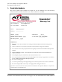
Axially-Compliant CNC
Robotic Deburring Tool
Installation and Operation Manual
9150-AC-180-CNC
Document #: 9610-50-1001-07
February 2010
Engineered Products for Robotic Productivity
Pinnacle Park • 1031 Goodworth Drive • Apex, NC 27539 • Tel: 919.772.0115 • Fax: 919.772.8259 • www.ati-ia.com • Email: [email protected]
CNC Hiac Installation and Operation Manual
Document: 9610-50-1001-07
!
CAUTION: This manual describes the function, application and safety
considerations of this product. This manual must be read and understood
before any attempt is made to install or operate the product, otherwise damage
to the product or unsafe conditions may occur.
Information contained in this document is the property of ATI Industrial Automation, Inc. (ATI) and shall not be reproduced in
whole or in part without prior written approval of ATI. The information herein is subject to change without notice. This manual
is periodically revised to reflect and incorporate changes made to the product.
The information contained herein is confidential and reserved exclusively for the customers and authorized agents of ATI
Industrial Automation and may not be divulged to any third party without prior written consent from ATI. No warranty including
implied warranties is made with regard to accuracy of this document or fitness of this device for a particular application. ATI
Industrial Automation shall not be liable for any errors contained in this document or for any incidental or consequential
damages caused thereby. ATI Industrial Automation also reserves the right to make changes to this manual at any time without
prior notice.
ATI assumes no responsibility for any errors or omissions in this document. Users’ critical evaluation of this document is
welcomed.
©Copyright by ATI Industrial Automation. All rights reserved.
How to Reach Us
Sales, Service and Information about ATI products:
ATI Industrial Automation
1031 Goodworth Drive
Apex, NC 27539 USA
www.ati-ia.com
Tel:
919.772.0115
Fax:
919.772.8259
E-mail: [email protected]
Technical support and questions:
Application Engineering
Tel:
919.772.0115, Option 2, option 2
Fax:
919.772.8259
E-mail: [email protected]
Pinnacle Park • 1031 Goodworth Drive • Apex, NC 27539 • Tel: 919.772.0115 • Fax: 919.772.8259 • www.ati-ia.com • Email: [email protected]
2
CNC Hiac Installation and Operation Manual
Document: 9610-50-1001-07
Table of Contents
1.
Tool Information.................................................................................................................................. 4
2.
General Data ........................................................................................................................................ 5
2.1
Environmental Limitations ......................................................................................................... 5
2.2
Extent of Warranties and Warranty Conditions ......................................................................... 5
3.
Handling, Storage, and Transportation ............................................................................................ 6
3.1
Inspection of Conditions when Delivered .................................................................................. 6
3.2
Unpacking and Handling ........................................................................................................... 6
3.3
Transportation and Protection during Transportation ............................................................... 6
3.4
Storage and Preventive Maintenance during Storage .............................................................. 6
4.
Description .......................................................................................................................................... 7
5.
Specifications...................................................................................................................................... 7
6.
Installation ......................................................................................................................................... 10
6.1
Tool Holder .............................................................................................................................. 10
6.2
Pneumatic Connections—Recommended (see Figure 4.4).................................................... 10
6.3
Pneumatic Connections—Alternate (See Figure 4.5) ............................................................. 11
7.
Operating Instructions ..................................................................................................................... 12
7.1
Adjusting the Drive Pressure (See Figure 4.5)........................................................................ 12
7.2
Adjusting the Axial Force (See Figure 4.5) ............................................................................. 12
7.2.1
7.2.2
7.3
7.4
7.5
7.6
7.7
7.8
Using Spindle Air........................................................................................................................12
Using External Air.......................................................................................................................12
General Word of Caution......................................................................................................... 13
How to Use the Deburring Tool ............................................................................................... 13
How the Deburring Tool Should Not Be Used......................................................................... 13
Tool Center Point (TCP) Position (See Figure 5.1)................................................................. 14
Programming ........................................................................................................................... 14
Safety Precautions .................................................................................................................. 15
8.
Maintenance Instructions................................................................................................................. 15
8.1
Regular Operational Maintenance........................................................................................... 15
8.2
Lubrication ............................................................................................................................... 16
8.3
Replacement of Files/Burrs (See Figure 6.1).......................................................................... 17
8.4
Replacement of Other Deburring Tool Parts........................................................................... 17
8.5
Overhaul .................................................................................................................................. 18
8.6
Tool Damages ......................................................................................................................... 18
9.
Spare Parts ........................................................................................................................................ 18
9.1
Recommended Spares............................................................................................................ 18
10. Terms and Conditions of Sale ......................................................................................................... 19
Pinnacle Park • 1031 Goodworth Drive • Apex, NC 27539 • Tel: 919.772.0115 • Fax: 919.772.8259 • www.ati-ia.com • Email: [email protected]
3
CNC Hiac Installation and Operation Manual
Document: 9610-50-1001-07
1. Tool Information
Due to the limited space available for written text on the deburring tool, some necessary
information has been written inside the crate. Please read this text carefully.
Speedeburr
Pinnacle Park, 1031 Goodworth Drive, Apex, NC 27539 USA
Tel: +1.919.772.0115
E-mail: [email protected]
Fax: +1.919.772.8259
www.ati-ia.com
Model:
______________
9150-AC-180-CNC
Serial no.:
______________
Deburring Tool
2.12 lbs.
Weight: _________
Output power:
Min/Max. file/burr diameter: ______
16 mm.
Air vane motor: ____________
Max. 25,000 RPM
_____________
250 W
Max. drive pressure: _______
75 psi.
WARNINGS:
•
Never use or start the tool without first reading and understanding the Installation and Operation
Manual.
•
Make sure that the tool is mounted as described in the Installation and Operation Manual.
•
Never use the tool for other purposes than those explicitly described in the Installation and Operation
Manual.
•
Make sure that the pneumatic control equipment is mounted as described in the Installation and
Operation Manual.
•
Only original spare parts and files/burrs delivered ATI must be used.
•
Never stand near the tool while it is started and running. If it is necessary to approach the tool while in
motion, stand behind appropriate Plexiglas windows.
•
Be aware of rotating parts.
•
A barrier to prohibit people from approaching the tool while in operation must secure the installation.
•
Be aware of high sound levels. Always use earplugs while working near the tool.
If the above instructions and instructions found in the Installation and Operation Manual are not followed,
no claims may be raised against ATI.
Pinnacle Park • 1031 Goodworth Drive • Apex, NC 27539 • Tel: 919.772.0115 • Fax: 919.772.8259 • www.ati-ia.com • Email: [email protected]
4
CNC Hiac Installation and Operation Manual
Document: 9610-50-1001-07
2. General Data
2.1
Environmental Limitations
General:
Area classification:
None
Gas group/ignition group:
None
Operation:
Installation position:
Unit has 1 ¼” shank for mounting in standard CNC
machine tool holder. The tool holder is not supplied by
ATI.
Storage:
Temperature range:
5°–35° C
41°–95° F
It is necessary to always store the tool in its crate and in a dry place. Also consult Section
3.4—Storage and Preventive Maintenance during Storage.
2.2
Extent of Warranties and Warranty Conditions
ATI Industrial Automation warrants the deburring tool identified by the serial number
printed on the deburring tool towards manufacturing errors one (1) year from the delivery
date. Delivery date is defined to be the date the deburring tool departs our production
facilities/warehouse.
The warranty is not valid for any part of the deburring tool used for other purposes than as
part of the Axially-Compliant CNC deburring tool.
The warranty is not valid if the user has disassembled the unit or attempted to disassemble
the unit and caused damage.
The warranty is not valid if handling, installation, storage, transportation, operation, or
maintenance of the deburring tool does not comply with the instructions given in the User
Manual.
The warranty is not valid if the warnings given are not obeyed.
If the instructions in this User Manual and other instructions given in writing accompanying
the Axially-Compliant CNC deburring tool are not followed, no claims whatsoever can be
raised against ATI or the supplier of the deburring tool.
Pinnacle Park • 1031 Goodworth Drive • Apex, NC 27539 • Tel: 919.772.0115 • Fax: 919.772.8259 • www.ati-ia.com • Email: [email protected]
5
CNC Hiac Installation and Operation Manual
Document: 9610-50-1001-07
3. Handling, Storage, and Transportation
3.1
Inspection of Conditions when Delivered
Upon receipt, the following should be checked:
- Deburring tool and other items delivered according to freight documents
- No damage to the package(s).
If there is damage to any wrapping, or if any of the goods have been exposed to abnormal
handling, unpack those parts that may have been damaged for a closer inspection. If
necessary, notify ATI for assistance in evaluation of the damages.
There are no requirements regarding preservation or preservation maintenance upon receipt.
The goods should be stored in a dry place.
3.2
Unpacking and Handling
The Axially-Compliant CNC deburring tool should, during transportation, storing, and
handling, always be placed inside the accompanying toolbox (crate).
3.3
Transportation and Protection during Transportation
When receiving the Axially-Compliant CNC deburring tool it is inside a wooden box,
specially suited for it. The form-fit packaging inside the box has the intention of securing the
deburring tool during transportation. Always use the box when transporting the AxiallyCompliant CNC deburring tool, in order to minimize the risk of damage to the deburring
tool. Handle with care.
The weight of the Axially-Compliant CNC deburring tool is approximately 2.12 lbs. In
addition to the deburring tool, other items such as adapters and burrs may be are placed
inside the box. This makes the total weight of the box approximately 6.4 lbs.
When taking the Axially-Compliant CNC deburring tool out of the box and carrying it, or
performing maintenance, try to always grasp and hold it with your fingers around the motor.
3.4
Storage and Preventive Maintenance during Storage
The Axially-Compliant CNC deburring tool should be stored in the wooden box when it is
not in use. It should also be stored indoors in a dry place.
For short-term storage (limited to a few weeks), no preventive maintenance is needed,
except for cleaning.
For long-term storage, in addition to cleaning, the Axially-Compliant CNC deburring tool
should be "filled" with oil, (i.e.; some oil of the same type as used as lubrication during
operation). It should be poured into the deburring tool through the air inlet. This is necessary
in order to avoid the blades in the air-vane motor from drying out and also for preventing the
risk of corrosion.
Pinnacle Park • 1031 Goodworth Drive • Apex, NC 27539 • Tel: 919.772.0115 • Fax: 919.772.8259 • www.ati-ia.com • Email: [email protected]
6
CNC Hiac Installation and Operation Manual
Document: 9610-50-1001-07
4. Description
Attached at the end of this document you will find the Axially-Compliant CNC deburring tool
product description.
5. Specifications
These are the main specifications for the Axially-Compliant CNC deburring tool:
Motor:
Air motor, vane type
Speed:
Idle 27,500 RPM ±10%, while deburring 18,000–25,000 RPM
Torque:
0.295 ft-lbs. at lower speeds
Power:
250 W at 20,000 RPM
Weight total:
2.12 lbs.
Weight FFP with file:
0.11 lbs.
Compensation, due to burr inaccuracy:
Max. +/- 4 mm in/out and sideways, recommended using +/-2 mm
Axial force:
At 0–75 psi inlet pressure
Normal range:
2.1–5.6 lbf
Light range:
0.79–1.5 lbf
File surface speed:
24.6–34.4 ft/sec, measured at 8mm diameter (halfway between
center tip and outer rim)
Air consumption:
Approx. 14.1 cu.ft./min, 75 psi line pressure
Sound pressure level:
78 dB(A)
Rotary burrs/files:
See Supplier Catalogue
Special tools:
Burr changing tool(s)
Path speed:
3.9 in/sec
Drive Air supply:
Recommended 75 psi (87 psi max)
spindle or external connections)
(through
Airborne noise emissions have been measured for an identical Axially-Compliant CNC deburring
tool (serial-production). All measurements were measured at a distance of 3.28 feet from the
surface of the deburring tool and at a height of 5.25 feet from the floor. The deburring tool was
mounted in a test-bench at our laboratory. No fences or noise-reduction facilities were used, except
for exhaust return to an oil-recovery unit, located beneath the test-bench. A drive-pressure of 75
psi was applied (full Axially-Compliant CNC deburring tool drive pressure). The AxiallyCompliant CNC deburring tool was running at full idle speed. Due to the fact that we do not know
what working environment the user will put the Axially-Compliant CNC deburring tool into or
what work pieces (types of materials) will be deburred, this was found to be the best method for
measurements.
The equivalent continuous A-weighted sound pressure level was measured to 78 dB(A).
Pinnacle Park • 1031 Goodworth Drive • Apex, NC 27539 • Tel: 919.772.0115 • Fax: 919.772.8259 • www.ati-ia.com • Email: [email protected]
7
CNC Hiac Installation and Operation Manual
Document: 9610-50-1001-07
Due to pressure losses between the pressure control valve and the Free Flying Piston (FFP), the
axial force is lower than theoretical calculations will predict. The actual force characteristics will
change from installation to installation, due to different types of pneumatic components used.
It is recommended that a working speed of 18,000 to 25,000 RPM be used for a maximum possible
output power. A lower speed than 18,000 RPM is not recommended, as it increases the risk of
stopping the motor, due to the higher torque at lower speeds.
Below are some theoretical and measured forces relative to applied air-pressure. Please note that
theoretical calculations are not necessarily identical to actual data. Measurements presented may
vary from deburring tool to deburring tool and should only be treated as informal in order to
understand the behaviour of the Axially-Compliant CNC deburring tool. Some actual data for your
deburring tool are found in the test certificate.
A x i a l c o n ta c t fo rc e
25
Axial force, in Newtons
20
15
F
10
5
0
0
0 ,2
0 ,4
0 ,6
0 ,8
1
1 ,2
1 ,4
1 ,6
1 ,8
2
2 ,2
2 ,4
C o n t r o l p r e s s u r e , in b a r s
Figure 4.1—Axial contact force, measured with rotary burr pointing downwards
Due to pressure losses between the pressure control valve and the Free Flying Piston (FFP), the
axial force is lower than theoretical calculations will predict. The actual force characteristics will
change from installation to installation, due to different types of pneumatical components used.
Pinnacle Park • 1031 Goodworth Drive • Apex, NC 27539 • Tel: 919.772.0115 • Fax: 919.772.8259 • www.ati-ia.com • Email: [email protected]
8
CNC Hiac Installation and Operation Manual
Document: 9610-50-1001-07
400
350
Rotor torque M, in Nmm
Output power P, in W
300
250
200
Torque
Pow er
150
100
50
0
0
5000
10000
15000
20000
25000
30000
Rotor velocity, in rpm
Figure 4.2— Axially-Compliant CNC deburring tool output torque and power. Theoretical calculations
30000
Rotary speed, in RPM
25000
20000
15000
Speed
10000
5000
0
0
1
2
3
4
Drive pressure, in bars
5
6
Figure 4-3—Idle speed as a function of applied drive pressure
Pinnacle Park • 1031 Goodworth Drive • Apex, NC 27539 • Tel: 919.772.0115 • Fax: 919.772.8259 • www.ati-ia.com • Email: [email protected]
9
CNC Hiac Installation and Operation Manual
Document: 9610-50-1001-07
6. Installation
6.1
Tool Holder
The tool holder is provided by the system integrator or by the owner/user of the HIAC.
6.2
Pneumatic Connections—Recommended (see Figure 4.4)
The recommended method for pneumatic connection is to the rear port (A), using air
supplied through the spindle.
Figure 4.4—Schematic Diagram
It is the user’s responsibility to provide a regulator and micro-fog system on the supply line.
The regulator should be set to a maximum of 87 psi.
The depth of the hole in the adapter must be less than 2.913” (74mm) in order to ensure a
proper seal with the O-ring in the end of the Axially-Compliant CNC deburring tool shaft.
The CNC machine has to be able to supply air through the spindle if internal air supply is to
be used. (Special tool holders with swivels and external air supply may also be used.)
Cooling air for the tools of the Axially-Compliant CNC deburring tool may be used as air
supply for the deburring tool. If so, lubrication has to be added to the air (mist lubrication).
Pinnacle Park • 1031 Goodworth Drive • Apex, NC 27539 • Tel: 919.772.0115 • Fax: 919.772.8259 • www.ati-ia.com • Email: [email protected]
10
CNC Hiac Installation and Operation Manual
Document: 9610-50-1001-07
6.3
Pneumatic Connections—Alternate (See Figure 4.5)
It is also possible to use the Axially-Compliant CNC deburring tool using pneumatic
connections external to the CNC machine.
Port (A) must be plugged. Supply air to drive the burr is provided through the 1/4” NPT Port
(B). It is the user’s responsibility to provide a regulator and micro-fog system on this supply
line. The regulator should be set to a maximum of 87 psi. Supply for the axial pressure is
provided through the 1/8” NPT Port (C). It is the user’s responsibility to provide a regulator
for this line. The range for this regulator should be approximately 0–75 psi.
E
B
D
C
A
F
Figure 4.5— Axially-Compliant CNC Deburring Tool Pneumatic Ports
Figure 4.6—Overview of the Axially-Compliant CNC Deburring Tool
Pinnacle Park • 1031 Goodworth Drive • Apex, NC 27539 • Tel: 919.772.0115 • Fax: 919.772.8259 • www.ati-ia.com • Email: [email protected]
11
CNC Hiac Installation and Operation Manual
Document: 9610-50-1001-07
7. Operating Instructions
7.1
Adjusting the Drive Pressure (See Figure 4.5)
For both pneumatic configurations, the 5 mm screw (E) can also be used to regulate the
drive pressure.
7.2
Adjusting the Axial Force (See Figure 4.5)
The contact force between the tool and the work piece is adjustable, with a choice between a
‘normal range’ and a ‘low range.’
- At 75 psi air pressure on the Axially-Compliant CNC deburring tool inlet the contact force in
the normal range is manually adjustable between 2.1 and 5.6 lbs.
- At 75 psi air pressure on the Axially-Compliant CNC deburring tool inlet, the contact force in
the low range is manually adjustable between 0.79 and 1.5 lbs.
The unit operates in the normal range when the two small vent holes (D) are plugged with
M2 screws. These vent holes are situated side-by-side on the lower part of the AxiallyCompliant CNC deburring tool, just above the locking ring.
The unit operates in the low range when only one of the vent holes (D) is plugged and the
other hole is open. Removing either one of the M2 screws opens a vent hole.
7.2.1
Using Spindle Air
When air to the unit is supplied through the spindle, the fine adjustment of each
range is made by turning the 5 mm screw (F).
This 5 mm screw is a threaded needle with a conical inner end that closes against
a conical seat inside the body. When the screw is turned clockwise, the contact
force will increase within its current range. By turning the screw counterclockwise, the contact force is decreased within its current range.
Once set, this screw should be locked into place using Loctite (low removal
force) or a similar adhesive to prevent it from moving.
The intention of the external pressure control valve (actually a regulator) is to
control the air-supply to the axial force compliance mechanism, thus enabling
control of the axial force on the rotary burr. If the complete work piece can be
deburred with equal axial force, a conventional manual pressure-regulator can be
used. If the burrs to be removed are varying from spot to spot on the work piece,
and this variation is repeatable for all work pieces of the same type, it might be
necessary to adjust the axial force for different spots on the work piece. This
adjustment can be performed by means of an analogue pressure-regulator,
controlled from the CNC machine. An analogue output port in the CNC machine
controller will be needed. As an alternative, several digital outputs may be
coupled to a digital-to-analogue converter (D/A-converter).
7.2.2
Using External Air
All alternatives to spindle air supply need to use a connection in accordance with
the pneumatic connection diagram. The drive air to the vane motor should be
mist lubricated by use of conventional pneumatic equipment. External air is
Pinnacle Park • 1031 Goodworth Drive • Apex, NC 27539 • Tel: 919.772.0115 • Fax: 919.772.8259 • www.ati-ia.com • Email: [email protected]
12
CNC Hiac Installation and Operation Manual
Document: 9610-50-1001-07
supplied through Port (C). Axial pressure should be controlled with the regulator
for that line.
It is recommended that a Ø5/16 in. plastic tube be used for the motor inlet, and
Ø5/32 in. tube for the contact force inlet. Note that a 1/8” NPT nipple is used to
connect the contact force inlet, and a 1/4” NPT for the motor inlet.
For the contact force pressure control valve, use a valve with a 45 psi max range.
When testing out the proper contact force, start with a very low pressure close to
zero, and increase slowly until desired chamfer is reached.
7.3
General Word of Caution
Although the operation of the Axially-Compliant CNC deburring tool, compared to other
deburring tools, is simple, it is important that everyone involved in operations involving the
deburring tool have a thorough understanding of the operating procedures. Failure to obey
these procedures or neglecting safety precautions can create hazardous situations that may,
in worst case, injure personnel or damage the deburring installation and the AxiallyCompliant CNC deburring tool. ATI is not responsible for such injuries and damages.
7.4
How to Use the Deburring Tool
The Axially-Compliant CNC deburring tool must only be used for CNC deburring
applications. The tool is a deburring tool only.
Never use the deburring tool for other purposes.
Never use the deburring tool in any other way than described here.
For further information, please consult Section 6—Installation and Section 7.7—
Programming.
7.5
How the Deburring Tool Should Not Be Used
Grinding, countersinking, or other metal-forming processes related should not be performed
by the Axially-Compliant CNC deburring tool. It may be dangerous to operate the deburring
tool for such purposes. If a breakage occurs due to acting forces that have not been taken
into consideration when designing the machine, machine parts may be thrown through the
air creating hazardous situations for both personnel and equipment. The only intention of the
Axially-Compliant CNC deburring tool is deburring.
Only work piece materials, as described in the product description, should be deburred by
use of a Axially-Compliant CNC deburring tool, except for variants of materials listed, that
as a result of the deburring operation may fracture. Work piece fracture may result in pieces
of material damaging surrounding working environment and personnel. The material
removed when correctly deburring should be in the form of chips.
Slow down the velocity when the work piece and the Axially-Compliant CNC deburring
tool are meeting. Making the contact movement between the deburring tool and the work
piece too hard may in some situations (e.g.; when the work piece is inaccurate) result in
collision. Collisions may create hazardous situations for both personnel and equipment.
Never use the Axially-Compliant CNC deburring tool as a hand-held tool. This is extremely
dangerous.
Pinnacle Park • 1031 Goodworth Drive • Apex, NC 27539 • Tel: 919.772.0115 • Fax: 919.772.8259 • www.ati-ia.com • Email: [email protected]
13
CNC Hiac Installation and Operation Manual
Document: 9610-50-1001-07
When performing maintenance, always remember to tighten nuts and bolts. When replacing
burrs/files, always attach the burr/file correctly. Please consult Section 8.3—Replacement of
Files/Burrs. This is important in order to avoid parts falling off the Axially-Compliant CNC
deburring tool.
In order to increase the life-length of the Axially-Compliant CNC deburring tool motor parts
and bearings, always use proper amounts of lubrication. Please consult Section 8.2—
Lubrication.
7.6
Tool Center Point (TCP) Position (See Figure 5.1)
The following drawing can be used to determine the tool center point (TCP) for the unit. The
dimension from the tool holder interface of the unit to the tip of the burr (4.942 in.) is based
on the burr being used at the midpoint of the 8 mm axial compliance. The user may prefer to
use the tool at some other point in the 8 mm range and will have to calculate the TCP
accordingly.
.472
Air Inlet
1.93
.640
.623
1.42
O-ring
1.26
.315
Axial
Stroke
1.17
1.686
4.942
1.25
7.784
Figure 5.1—TCP Dimensions
7.7
Programming
Install the Axially-Compliant CNC deburring tool as described in Section 6—Installation.
To obtain a good result, it is important that the piston is running with low friction in the
cylinder. Please consult Section 8.1—Regular Operational Maintenance.
For instructions of how to replace the burr, please consult Section 8.3—Replacement of
Files/Burrs.
Under normal conditions, no cooling or lubrication of the rotary burr is necessary. The
Axially-Compliant CNC deburring tool is used in several CNC deburring installations with
aluminum and steel work pieces without any cooling additives. Clogging of the file is not
expected to be a problem.
The Axially-Compliant CNC deburring tool must never be running during programming.
Pinnacle Park • 1031 Goodworth Drive • Apex, NC 27539 • Tel: 919.772.0115 • Fax: 919.772.8259 • www.ati-ia.com • Email: [email protected]
14
CNC Hiac Installation and Operation Manual
Document: 9610-50-1001-07
When programming the CNC machine, it is important that the program is based on a
previously deburred work piece. Program the points with the burr in its mid- position
(approximately) in the axial direction, and halfway between the tip and outer rim of the burr
(i.e.; on a 4 mm radius for an 8 mm radius burr). If you are deburring sharp inner corners, it
may be required to move closer to the tip of the file. Note that you, in this case, loose some
of the position compensation ability of the burr.
When running the CNC program for the first time, you should observe the path with the
Axially-Compliant CNC deburring tool left off. When increasing the path speed, it is
important to notice the path deviation that increases with speed. Be careful never to allow
the contact between work piece and carbide burr to enter so far on the burr's outer rim that it
"falls down" and misses the edge. This may be dangerous for the Axially-Compliant CNC
deburring tool and especially for the Free Flying Piston.
To change the axial force of the burr, in order to achieve a correctly-sized and even chamfer,
please refer to Section 7.1—Adjusting the Drive Pressure and Section 7.2—Adjusting the
Contact Force.
IMPORTANT: The Axially-Compliant CNC deburring tool must never run without proper
lubrication. Please consult Section 8.2—Lubrication.
7.8
Safety Precautions
The only working environment allowable for the Axially-Compliant CNC deburring tool is
together with a CNC machine in a secured dedicated working chamber.
The operator must never be present in the working chamber while the Axially-Compliant
CNC deburring tool is running.
Beware of rotating parts. Use eye-protection (e.g.; protection glasses).
Beware of high sound level. Always use ear protection while working in the neighborhood
of the deburring cell/CNC machine
For further safety precautions please consult Section 1—Tool Information.
8. Maintenance Instructions
8.1
Regular Operational Maintenance
To obtain a good result, it is important that the piston is running with low friction in the
cylinder. This must be taken care of during operation. Some debris will always enter the
cylinder and regular cleaning at weekly intervals, or each time the rotary file is changed, is
recommended. Also, clean the outside of the Axially-Compliant CNC deburring tool to
ensure proper cooling.
The burr needs to be replaced at regular intervals. During commissioning of the deburring
installation, the burr and the work piece should be examined often in order to determine at
what intervals the burr needs to be replaced. For instructions of how to replace burrs, please
consult Section 8.3—Replacement of Files/Burrs.
At regular intervals (normally once every year or more often depending on the application)
an overhaul of the tool should be performed in order to fully comply with the technical
specifications. Parts inside the Axially-Compliant CNC deburring tool, such as the blades in
Pinnacle Park • 1031 Goodworth Drive • Apex, NC 27539 • Tel: 919.772.0115 • Fax: 919.772.8259 • www.ati-ia.com • Email: [email protected]
15
CNC Hiac Installation and Operation Manual
Document: 9610-50-1001-07
the air-vane motor and bearings should be replaced as part of such an overhaul. Please
consult Section 8.5—Overhaul.
At regular intervals, the air-filter and lubricator should be checked. Remember at regular
intervals to fill up the lubricator with oil to provide micro-fog lubrication. It must never dry
out!
Fill the lubricator with the proper type of oil at regular intervals.
8.2
Lubrication
Before start-up, make sure the air lubrication system is filled with oil. Use oil similar to
machine oil #10, spindle oil #60 or thinner, Shell/Exxon ATF Dexron II automatic
transmission oil, or similar.
Oilfog air lubrication systems are not recommended as a means for providing lubricated air
for this product. Only microfog systems should be used. The system should be adjusted to
10–15 drops per minute. Only part of the oil drop actually enters the air stream. Fill the
lubricator with the proper type of oil at regular intervals.
!
CAUTION: When the system is first installed, use a higher than recommended
oil setting (~2 times) until the unit is receiving consistently oiled air. If possible,
run oil through the entire pneumatic tube between the oiler and the unit prior to
operation.
It is recommended that the exhaust containing lubrication be filtered through an oil-recovery
system before exhausting it to the atmosphere. Long-time exposure to air containing oil
could be dangerous for personnel.
!
CAUTION: Lack of lubrication will cause untimely wear on the motor and failure
within a relatively short period. If the lubrication is not working properly, the
motor will run slower than normal, and may vary in speed. Install the lubrication
equipment near the robot base (maximum 16 feet from the HIAC) for best
results.
Important:
Lack of lubrication will cause destruction of the motor (rotor blades) within a relatively
short time. If the lubrication is not working properly, you can hear the motor running slower
than normal and varying in speed. Install the lubrication equipment near the CNC machine
(maximum 16 feet away from the Axially-Compliant CNC deburring tool) for the proper
effect.
For environmental reasons, please let the exhaust containing lubrication be filtered through
an oil-recovery system, before letting it out in the atmosphere. Long-time exposure of air
containing oil is dangerous for the operating personnel.
Pinnacle Park • 1031 Goodworth Drive • Apex, NC 27539 • Tel: 919.772.0115 • Fax: 919.772.8259 • www.ati-ia.com • Email: [email protected]
16
CNC Hiac Installation and Operation Manual
Document: 9610-50-1001-07
8.3
Replacement of Files/Burrs (See Figure 6.1)
The burr-changing tool is shown below. To release the Axially-Compliant CNC deburring
tool piston, unscrew the lock nut by using the accompanying hook spanner (3810-51-1004).
Pull the cylinder out carefully, maintaining the piston’s position. If obvious sideways play is
detected, the cylinder and/or the piston must be replaced. If the carbide file is worn, unscrew
it with the burr-changing tool, and replace it with a new one. After checking, re-install in the
cylinder, and then re-install the cylinder on the Axially-Compliant CNC deburring tool. The
lock nut should be screwed into position and tightened lightly by using the hook spanner.
Burr Tool Holder Assembly
9040-51-1001
Rotary Carbide File
FFP
9005-51-1000
All Tools are in
Pincer Assembly
9040-51-1000
Burr Change Tool Kit
9040-51-1002
Figure 6.1—Burr Replacement Tools
After the file is changed, check that the Free Flying Piston (FFP) is rotating with the file. If
the FFP is not rotating, static friction may be interfering so the axial force cannot remain
constant. In that case, clean the FFP and inspect for any visible scratches. If a file with an
imbalance is used, the FFP may also stop rotating. All files are checked for imbalances
before they leave ATI Industrial Automation.
Only original files/burrs delivered from ATI must be used.
8.4
Replacement of Other Deburring Tool Parts
Beside the burrs, deburring tool parts such as the blades in the air-vane motor and bearings
should be replaced at regular intervals. We recommend that ATI perform this as a part of an
Axially-Compliant CNC deburring tool overhaul. Please consult Section 8.1—Regular
Operational Maintenance and Section 8.5—Overhaul.
We have designed the Axially-Compliant CNC deburring tool for a long lifetime. Except for
the parts described above, replacement is very seldom necessary when the deburring tool is
used for normal deburring applications.
Pinnacle Park • 1031 Goodworth Drive • Apex, NC 27539 • Tel: 919.772.0115 • Fax: 919.772.8259 • www.ati-ia.com • Email: [email protected]
17
CNC Hiac Installation and Operation Manual
Document: 9610-50-1001-07
Experience has shown that during installation, programming, run-off, and sometimes during
operation, the Axially-Compliant CNC deburring tool and the work piece collide, or the
radial forces acting are too large due to poor programming or work piece inaccuracy. This
sometimes results in destruction of the cylinder and/or the FFP and requires that they be
replaced. The procedure for replacing these components is similar to the description given in
Section 8.3—Replacement of Files/Burrs.
Only original spare parts delivered from ATI must be used.
8.5
Overhaul
As described in previous sections of this User Manual, at regular intervals, the motor unit
and free flying spindle may be inspected and overhauled. In addition to the above, the
Axially-Compliant CNC deburring tool is thoroughly cleaned, inspected, and tested. We
recommend that this overhaul be performed by ATI in order to maintain the technical
specifications and life of the unit.
8.6
Tool Damages
For repair of deburring tool damages and replacement of spares other than those given in our
price-list, please contact ATI.
9. Spare Parts
Spare parts and answers to technical questions are available from ATI Industrial Automation (the
distributor of the Axially-Compliant CNC deburring tool).
9.1
Recommended Spares
Based on the information given in this document, we recommend that the following spare
parts be stocked by the user, in addition to burrs/files:
P/N
Description
9005-51-1000
Free Flying Piston (FFP)
3700-51-1009
Cylinder
Only original spare parts and files/burrs delivered from ATI should be used.
Pinnacle Park • 1031 Goodworth Drive • Apex, NC 27539 • Tel: 919.772.0115 • Fax: 919.772.8259 • www.ati-ia.com • Email: [email protected]
18
CNC Hiac Installation and Operation Manual
Document: 9610-50-1001-07
10. Terms and Conditions of Sale
The following Terms and Conditions are a supplement to and include a portion of ATI’s Standard Terms and
Conditions, which are on file at ATI and available upon request.
ATI warrants to Purchaser that robotic tool changer products purchased hereunder will be free from defects in
material and workmanship under normal use for a period of three (3) years from the date of shipment. This warranty
does not cover components subject to wear and tear under normal usage or those requiring periodic replacement.
ATI will have no liability under this warranty unless: (a) ATI is given written notice of the claimed defect and a
description thereof within thirty (30) days after Purchaser discovers the defect and in any event not later than the
last day of the warranty period; and (b) the defective item is received by ATI not later ten (10) days after the last
day of the warranty period. ATI’s entire liability and Purchaser’s sole remedy under this warranty is limited to
repair or replacement, at ATI’s election, of the defective part or item or, at ATI’s election, refund of the price paid
for the item. The foregoing warranty does not apply to any defect or failure resulting from improper installation,
operation, maintenance or repair by anyone other than ATI.
ATI will in no event be liable for incidental, consequential or special damages of any kind, even if ATI has been
advised of the possibility of such damages. ATI’s aggregate liability will in no event exceed the amount paid by
purchaser for the item which is the subject of claim or dispute. ATI will have no liability of any kind for failure of
any equipment or other items not supplied by ATI.
No action against ATI, regardless of form, arising out of or in any way connected with products or services supplied
hereunder may be brought more than one (1) year after the cause of action occured.
No representation or agreement varying or extending the warranty and limitation of remedy provisions contained
herein is authorized by ATI, and may not be relied upon as having been authorized by ATI, unless in writing and
signed by an executive officer of ATI.
Unless otherwise agreed in writing by ATI, all designs, drawings, data, inventions, software and other technology
made or developed by ATI in the course of providing products and services hereunder, and all rights therein under
any patent, copyright or other law protecting intellectual property, shall be and remain ATI’s property. The sale of
products or services hereunder does not convey any express or implied license under any patent, copyright or other
intellectual property right owned or controlled by ATI, whether relating to the products sold or any other matter,
except for the license expressly granted below.
In the course of supplying products and services hereunder, ATI may provide or disclose to Purchaser confidential
and proprietary information of ATI relating to the design, operation or other aspects of ATI’s products. As between
ATI and Purchaser, ownership of such information, including without limitation any computer software provided to
Purchaser by ATI, shall remain in ATI and such information is licensed to Purchaser only for Purchaser’s use in
operating the products supplied by ATI hereunder in Purchaser’s internal business operations.
Without ATI’s prior written permission, Purchaser will not use such information for any other purpose or provide or
otherwise make such information available to any third party. Purchaser agrees to take all reasonable precautions to
prevent any unauthorized use or disclosure of such information.
Purchaser will not be liable hereunder with respect to disclosure or use of information which: (a) is in the public
domain when received from ATI; (b) is thereafter published or otherwise enters the public domain through no fault
of Purchaser; (c) is in Purchaser’s possession prior to receipt from ATI; (d) is lawfully obtained by Purchaser from a
third party entitled to disclose it; or (f) is required to be disclosed by judicial order or other governmental authority,
provided that, with respect to such required disclosures, Purchaser gives ATI prior notice thereof and uses all
legally available means to maintain the confidentiality of such information.
Pinnacle Park • 1031 Goodworth Drive • Apex, NC 27539 • Tel: 919.772.0115 • Fax: 919.772.8259 • www.ati-ia.com • Email: [email protected]
19