1
556
Applications and Experiences of Quality Control
used, the former that quantifies the general matching of whole images and the latter that
inspects smaller areas of interest.
Finally, an example of colour intensity determination of plastic parts for aesthetic goods will
be presented. This application has the aim to solve the problem of pieces which could
appear too dark or too light with respect to a reference one, and also to identify defects like
undesired striation or black point in the pieces, depending on mixing condition of virgin
polymer and masterbatch pigment. Use of pixel intensity and histograms have been adopted
in the development of these procedures.
2. System description
In this section, the hardware and software architecture of the system will be described.
The hardware is composed by a camera, a telecentric zoom lens, two lights, a support for
manual handling of pieces, and a PC.
The camera is a monochromatic camera with a CCD sensor (model AVT Stingray F201B ®).
The sensor size is 1/1.8”, and its resolution is 1624 x 1234 pixel, with a pixel dimension of 4,4
μm, a colour depth of 8 bit (256 grey levels) and a maximum frame rate of 14 fps at full
resolution. The choice of a CCD sensor increases image quality, reducing noise in the
acquisition phase and the high resolution (about 2 MPixel) leads to an acceptable spatial
resolution in all the fields of view here adopted.
The optics of the system is constituted by a telecentric zoom lens (model Navitar 12X
telecentric zoom.®); the adopted lens is telecentric because it permits to eliminate the
perspective error, which is a very useful property if one desires to carry out accurate
measurements. The zoom system permits to have different field of view (FOV), so the FOV
can vary from a minimum of 4,1 mm to a maximum of 49,7 mm. The zoom is moved by a
stepper driving, and the software can communicate and move it automatically to the desired
position. The utility of this function will be clear later, when the start-up procedure is
explained.
The depth of focus varies with the FOV, ranging from 1,3 mm to 38,8 mm; the mentioned
camera and lens features bring to a maximum resolution of the system of 0,006 mm (FOV 4,1
mm) and a minimum resolution of 0,033 mm (FOV 49,7 mm).
To lights the scene, a back light and a front light were adopted. Both have red light, to
minimize external noise and to reduce chromatic aberration. Moreover they have a coaxial
illumination, that illumines surface perpendicularly and increases contrast in the image
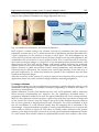
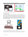
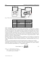
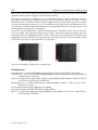
highlighting edge and shapes and improving the general quality of the image. In figure 1.a
the complete system is showed. All the components are managed by a PC, that use a specific
software developed in LabView®.
Its architecture is reported in figure 1.b. It has a user interface, that guides step by step the
operator through the procedures for the different controls. So, the operator is called only to
choose the application to use, then to load pieces in the work area and to shot photos. Every
time he shots, image is acquired and processed (and stored if necessary), so the result is
given almost immediately. If the operator needs to control a production batch, it is also
possible to acquire several images consecutively and then post-process all of them exporting
global results in an excel file.
All this operations are possible thank to the background software, that answer to the
operator input. In fact, when the operator select the kind of control, the software load all the
parameters necessary to the analysis. For each application, the software load all parameters
www.intechopen.com