1
563
Digital Image Processing for Quality Control on Injection Molding Products
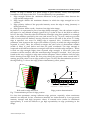
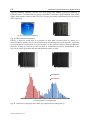
This can be avoided applying filters to the image before edge determination process. In this
application, a filter to increment contrast was applied. This allow to reduce the steepness to
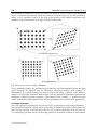
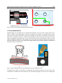
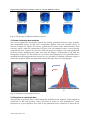
two pixels only, and the filter width also to four pixels only. In fig.8 filter effects on the
image are shown; fig. 8.a represents the original image acquired, fig. 8.b reports filtered
image with increased contrast.
a)
b)
Fig. 8. a) original image, b) aligned and filtered image
To increment contrast in the image, it’s also possible to increment illumination intensity but
in this case the light passes through the material in a huge way and the dimension of the
part will be undervalued, so this method have to be used carefully.
This process have to be done confronting image results with contact methods or other
suitable techniques; in particular, standard caliper measurement was used here.
3.1 Simple feature measurement
In this section, measurement process of simple feature will be illustrated. A simple feature is
a feature that requires the identification of two elements, then some dimensional or
geometric information are extracted by them. Features number 1, 3 and 4 of fig. 6.b are
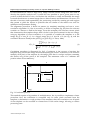
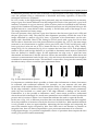
representative of this case. Feature number 1 will be treated as example. The objective is to
determine the diameter of the part. As previously explained, two search areas have to be
determined. The region may have the desired shape (circular, rectangular, square,
polygonal) depending on the feature to inspect. In this case, because a line is searched, two
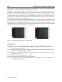
rectangular ROI are defined (green rectangles in fig. 8.b). The ROI has fixed size and fixed
position in the image; hence, alignment process is important in order to bring the part
always in the same position in the image, permitting the software to find the edge at all
times, with high reliability and robustness. A rake division of five pixels has been used
(distance between each inspection line), it means that a point every 0,085 mm is stored
(about 40 points per line). When points are determined, they are used to fit a line with a
linear regression method and to determine the equation of the line in the image.
Once the equation has been determined, the process is repeated for the second edge, to
determine the second equation. The rectangular search area is the same and has the same x
position; this is important to define distance in following steps.
Now, using the equations is possible to find all the information required analytically.
Defining first line as reference line, maximum and minimum distance between the lines has
www.intechopen.com