1
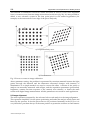
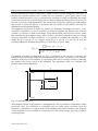
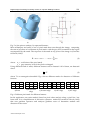
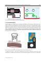
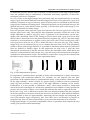
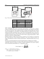
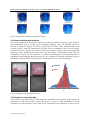
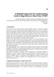
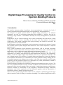
561
Digital Image Processing for Quality Control on Injection Molding Products
a)
b)
Fig. 5. a) the piece to analyse, b) requested features
More techniques are based on use of pixel mask that runs through the image, computing
the sum of products of coefficients of pixel mask with the gray level contained in the region
encompassed by the mask. The response of the mask at any point of the image is (Gonzales
& Woods, 1992):
R = w1 z1 + w2 z2 + ..... + w9 z9 = ∑ wi zi
9
(2)
i= 1
where: wi = coefficient of the pixel mask;
zi = gray intensity level of the pixel overlapped.
Using different kind of mask, different features can be detected. All of them, are detected
when:
R >T
(3)
where T is a nonnegative threshold. Fig. 6 shows different masks for detection of different
features.
-1
-1
-1
-1
8
-1
-1
-1
-1
a)Point
-1
2
-1
-1
2
-1
-1
2
-1
b)Horizontal
edge
-1
-1
-1
2
2
2
-1
-1
-1
c)Vertical edge
-1
-1
2
-1
2
-1
2
-1
-1
d)+45° edge
2
-1
-1
-1
2
-1
-1
-1
2
e)-45° edge
Fig. 6. Different pixel mask for different features
In this application, an easier method, based on pixel value analysis along a pixel line, has
been used. It is a simplification of derivative operators method (Gonzales & Woods, 1992)
that uses gradient operators and analyses gradient vector to determine module and
direction of the vector.
www.intechopen.com