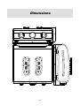
1
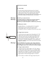
Talia
Stereophonic
Preamplifier
User manual
Important Safety Instructions
1. Read these instructions.
2. Save these instructions.
3. Pay attention to all advices.
4. Always follow instructions.
5. Do not use this unit in presence of water.
6. Clean with a dry cloth only.
7. Do not obstruct venting holes and heat sinks. Install as indicated by the manufacturer.
8. Do not install near heat sources such as heaters, heat pumps, stoves or other equipment which
produce heat.
9. Do not alter the functionality of a polarized plug or one provided with earth connection. A plug is
polarized when it can be fitted in the mains socket in one way only. A plug provided with earth
connection has two prongs for current and a third one for earth connection. The latter is provided for
user’s safety. If the plug provided doesn’t fit your mains socket, consult your technician to obtain the
replacement of the obsolete mains socket.
10. The mains cable represents the emergency detachment device for this unit. It’s important to grant a
quick access to this cable in every moment.
11. Protect the mains cable against trampling and mashing, particularly close to the plug and to the
connector at the input socket of the unit.
12. Use only connectors and accessories specified by the manufacturer.
13. Only use the cart, stand, tripode or table specified by the manufacturer or sold with the unit. When
using a cart, pay attention while shifting the cart/unit ensemble to avoid harming people or flipping
the cart upside down.
14. Isolate the unit from mains during lightning storms or when it’s not operated for long.
15. Refer all servicing to qualified personnel. Servicing is required when the unit is damaged due to any
reason, e.g. when mains cable or plug are damaged, when a liquid is spilled on it or when objects
drop on the unit, when the unit is exposed to rain or moisture, or when the unit is not operative or has
been dropped from whatever height. The replacement of the outer shell must be considered a service
operation.
16. Venting must not be impeded by obstructing venting holes and heat sinks with objects like
newspapers, towels, curtains and the like.
17. Do not place any free flame, like a candle or the like, on the unit.
18. Terminals marked with this label must be considered DANGEROUS and the connections external to
these terminals require servicing by a TRAINED TECHNICIAN or the use of factory prepared
cables.
Warning!
To reduce the risk of fire or electric shock, do not expose this unit to rain or to
moisture. Do not place objects containing liquids, like bowls or glasses, on this
unit.
2
Warning!
Changes or modifications not authorized by the manufacturer can invalidate the
compliance to CE regulations and can cause the unit not to be suitable for use any
longer. The manufacturer rejects any responsibility regarding damages to people or
to things caused by the use of a unit which has been subject to unauthorized
modifications or caused by the misuse or by the malfunction of a unit which has
been subject to unauthorized modifications.
3
Instructions for Recycling
The label on the left, printed on the envelope of the product, indicates that the product,
when no more usable, can’t be treated as generic garbage. The product must be disposed
of at a collection point for recycling of electrical and electronic equipment, in
compliance with WEEE regulations (Waste of Electrical and Electronic Equipment).
By making sure that this unit is correctly recycled, you will help preventing potential
damages to the environment and to human health. Recycling helps saving natural
resources. For more in-depth information about recycling this product, please contact
Absoluta Sound and Space Srl.
ABSOLUTA SOUND AND SPACE
Galleria Andrea Urbani, 3
35027 Noventa Padovana (PD)
Ph. :
Fax.
Web:
+39.049.8935377
+39.049.8935377
www.absoluta.it
Customer Service
Phone:
+39.049.8935377
Fax:
+39.049.8935377
e-mail:
[email protected]
P/N: 1234557 – Rev. 1.0 – 03/09
“Absoluta Sound and Space” and the logo Absoluta
are registered trademarks of Absoluta Sound and
Space Srl.
© Absoluta Sound and Space Srl. All right reserved.
This manual should not be construed as a
commitment on the part of Absoluta Sound and
Space Srl. The information it contains is subject to
changes without notice. Absoluta Sound and Space
assumes no responsibility for errors that may appear
within this document.
4
Safety Terms and Symbols
This document contains instructions on generic safety,
installation and use for the Talia stereophonic preamplifier. It’s
important to read this document before trying to use this
amplifier. Pay particular attention to safety instructions.
Appears on the unit to indicate the presence
of uninsulated, dangerous voltages inside
the enclosure - voltages sufficient to constitute
a risk of shock.
Appears on the unit to indicate important
operation or maintenance instructions included
in the accompanying documentation.
Appears on the unit to indicate compliance
with the EMC (Electromagnetic Compatibility
and LVD (Low-voltage Directive) standards
of the European Union.
Warning!
Calls for attention to a procedure, practice
condition, or the like that, if not correctly
performed or adhered to, could result in
personal injuries, death or damages to the unit
or to other objects.
Note
Calls for attention to information that is
essential to highlight
5
This page has been intentionally left blank
6
Table of Contents
Introduction ..................................................................... 9
Special Design Features ................................................... 9
Unpacking ....................................................................... 12
Installation Considerations .............................................. 13
Power Requirements ...................................................... 15
Operation ....................................................................... 17
Front Panel ..................................................................... 17
Back Panel ...................................................................... 20
Remote Control ............................................................... 26
Connections .................................................................... 29
General Connections Scheme ........................................ 31
Balanced Connection to Power Amplifier ........................ 33
Troubleshooting............................................................ 35
Maintenance .................................................................. 35
Troubleshooting .............................................................. 35
Maintenance ................................................................... 38
Specifications................................................................ 39
Dimensions.................................................................... 41
7
This page has been intentionally left blank
8
Introduction
Special Design Features
Design Principles
Dear Customer, thank you for purchasing Talia stereophonic
preamplifier. Talia combines the performance, versatility, purity
and definition of a great multi-chassis preamplifier with the
small form factor of an integrated preamplifier. It delivers the
great sound, that only the best products can deliver, and has an
original and captivating look.
Below you will find a description of all the features that make
Talia a unique and valued product.
Customizable
external shell
Talia, like all Absoluta products, features an external removable
shell, that can be easily replaced, to adapt the look of the
preamplifier to the furniture style and to better match the
owner’s taste. The shell is available in various standard finishes.
In addition to standard finishes the customer can request custom
versions, choosing amongst several materials and colors.
Highest class
components
Talia is made with first-class components, like the encapsulated
toroidal transformer with reduced stray flux and large
bandwidth, low noise and great linearity selected tubes, low
tolerance polypropylene capacitors and special low noise
resistors for audio use.
Extremely refined
power supply
DC-coupled
balanced tube line
stage
The double layer printed circuit boards host specific functions to
grant the maximum separation amongst the various parts of the
circuit. Their structure is optimized for signal path and for
power connections minimization.
Each circuit section is powered by a dedicated regulated supply
section. Each of the double triodes which make the gain stage of
the line and the MM phono amplifiers have their own heat
supply, independent from the transformer secondary winding.
B-rail supplies are separated for each channel and regulated with
discrete components circuits. Additional filter blocks further
reduce ripple and noise.
Absoluta has seen a major sound detriment in the non-linear
operation of capacitors’ dielectric. For this reason, Absoluta
power amplifiers use totally DC-coupled circuits. Much more
difficult has been to implement a DC-coupled tube circuitry
from input to output. Absoluta succeeded by using a “folded
9
Special Design Features – Design Principles (continued)
cascole” differential pair with common anode output buffer.
This layout allows for automatic signal balancing (be it applied
in single-ended or in differential mode), an ample bandwidth
and a reduced output impedance, all at the same time and with
the sound quality that only tubes give, without feedback.
Thanks to the automatic balancing feature, a single-ended and a
balanced signal are always available on outputs (on RCA and
XLR connectors, respectively), no matter the kind or source
selected. This is obtained without using integrated circuits to
balance the signal. Talia is provided with a balanced input.
Volume control is made with a sophisticated motor-operated
four-section potentiometer. Muting and phase inversion
features, as well as input selection, are implemented with high
quality audio grade relay.
Complete and
versatile hybrid
phono stage
The phono stage allows for using either high output (MM or
high output MC, “moving flux”, moving iron) and low output
(MC) pick-ups. The MM amplification and RIAA equalization
stage uses a double triode per channel. Gain is selectable
amongst various values to match to different output pick-ups. It
is possible to choose between two different input resistance
values (optimized for MM or high output MC) and three
capacities.
The MC pre-preamplifier is made with a very low noise and
very low distortion operational amplifier. It allows for choosing
between two gain settings and three input impedance settings
for each gain value, so as to optimize the interface with both
normal ferrite magnets MC and AlNiCo magnets MC, which
come with higher efficiency and thus lower output impedance.
Great control
flexibility
All Talia features are implemented by a microcontroller. It
receives commands by the controls on the front panel or by a
remote control. Some features (as phase inversion of selected
input or front panel’s led indicators switch off) are available on
the remote control only. Talia may also be set in standby, mode
in which its power consumption is strongly reduced, while
complete switch-off is obtained by operating the main power
switch on the back panel, close to the mains socket.
Talia is also provided with a trigger input for remote activation
by an external controller, and with a 12VDC trigger output to
activate another component. Moreover, an input for a remote IR
sensor is available. This allows to extend the range of the
remote control or to control Talia with an IR repeater from a
controller.
10
Special Design Features – Design Principles (continued)
Protections against
DC offset
Being its line circuit DC-coupled, Talia is provided with
sophisticated protection circuits against DC offset on its outputs,
to protect both the power amplifiers and the loudspeakers.
Talia’s controller continuously monitors the offset on outputs
and when it grows beyond a safety limit, the output relay
disengage and the outputs are effectively isolated until the offset
disappears.
A part of this circuit manages the burn-in transient of the tubes
at switch-on.
11
Unpacking
Warning!
Failure to follow the procedures included in this section
may result in personal injuries and/or produce damage to
the unit. DO NOT try to lift or move Talia without adequate
assistance.
Talia is a heavy and massive preamplifier. Its weight is 14.5 kg
(32 lbs.) without packaging, 28.5 kg (63 lbs.) with packing.
Don’t get fooled by its small size: its weight is enough to cause
injuries to your spine, more so when it’s not possible to use a
correct lifting technique. Two people are required to lift and
shift Talia.
Warning!
DO NOT try to extract Talia from its packing without help.
DO NOT try to lift Talia while bending on it. When lifting it,
keep your back vertical as much as possible, using legs to
lift the amplifier.
When extracting Talia from its packaging:
● DO save all packaging materials for possible future shipping
needs.
● Do inspect Talia for signs of damage that may have occurred
during shipment.
If damage is discovered, contact an Absoluta authorized
dealer for assistance.
12
Installation Considerations
Talia requires special care during installation to ensure optimal
performance. Pay particular attention to the precautions
included in this section and to other precautions included
throughout this owner’s manual.
Placement
● DO review “Important Safety Instructions” and “Power
Requirements” before installing Talia.
● Do place Talia on a solid, flat, level surface, such as a
table, a shelf or the floor.
● DO position Talia as close as possible to you, placing
the power amplifiers close to the loudspeakers so as to use
short speakers cables. Use, if necessary, longer interconnect
cables between Talia and the power amplifiers. This is to
be preferred because interconnect cables pass low-voltage
signals, which transmit over distances with greater
accuracy than the high-voltage signals required by loudspeakers.
● DO allow at least 15cm clearance behind Talia for the power
cord and other cables to bend without crimping or straining.
● DO see “Dimensions” for assistance with custom
installation.
● DO NOT place Talia close to components which generate
high power signals. Talia is a large bandwidth component and
it’s sensible to stray magnetic fluxes, sometimes capable of
coupling noise into some particularly sensitive components
like Talia.
● DO NOT place Talia on a windowsill or in any another
location in which it will be exposed to direct sunlight. Solar
radiations can damage the external shell and alter its color.
Warning!
BEFORE moving Talia, make sure it is powered off using
the power cocker switch on the back panel. Then, make
sure that the power cord is disconnected from the AC
mains connector and from the power outlet.
DO NOT attempt to move Talia without adequate
assistance. Proper lifting requires at least two people.
Ventilation
Talia dissipates the heat produced during operation through two
massive heat sinks placed laterally to the cabinet, and through
several venting holes located on the bottom of the cabinet, and
on the top cover of the amplifier. The hot air coming out of
these holes finds it way thanks to a particular design of the
external shell.
13
Installation Consideration (continued)
When Talia is placed in a position in which a correct air flow is
allowed, its proper operation is ensured no matter what the
temperature of the surrounding environment is.
Due to the high heat dissipation of tubes and of power devices
used for power supply regulation, Talia produces relevant heat
during its operation. The cabinet and even the front panel knobs
can become quite warm. Please consider that a temperature of
40°C makes metal surfaces hot when touched with bare hands.
However this should not cause any concern because Talia is
designed to operate at such temperatures.
● DO select a dry, well-ventilated position, out of direct
sunlight.
● DO NOT obstruct venting holes on the bottom of the cabinet,
on the top or on the outer shell. Do not reduce air flow
through and around Talia’s cabinet.
● DO NOT place Talia on a thick carpet. Do not cover it with a
cloth, as this would prevent proper cooling. If Talia is placed
on the floor, use a thick tempered glass sheet to provide a
stable base and to provide adequate venting.
● DO NOT expose Talia to high temperature, humidity, steam,
smoke, dampness or excessive dust. Avoid installing Talia
near radiators and other heat-producing appliances.
14
Power Requirements
Talia is configured to operate at the voltage present in the
country where it is sold. Before activating Talia, make sure that
the label on the back panel indicates the right mains voltage.
Warning!
DO NOT attempt to adjust the operating voltage. Consult
an authorized Absoluta dealer if the operating voltage is
incorrect or if the operating voltage must be changed for
relocation purposes.
BE ADVISED that different operating voltages may require
the use of different power cords and/or attachment plugs.
Contact an authorized Absoluta dealer for assistance.
Even if Talia doesn’t require relevant supply currents, other
components in your hi-fi system can produce relevant current
absorption. In this case, consider installing a dedicated AC
circuit for the home entertainment system. Contact a licensed
electrician for assistance. If more than one electric circuit is
providing power to the system, contact a licensed electrician to
ensure that all components are operating with the same, solid
low-impedance round reference.
Note
Warm-up & break-in
period
Tubes wear-out
Operating modes
Building regulations and electrical codes differ from location to
location, making it impossible to anticipate the requirements of
AC circuits used to supply Talia. Contact a local, licensed
electrician for information.
Although Talia delivers superior performance from the first time
it’s powered on, this performance will continue to improve as
the power amplifier reaches its normal operating temperature
and various components “break-in”. The greatest performance
improvements will occur within the first 100 hours of use.
Sound quality will continue to improve for about 300 hours.
After this initial period, Talia’s performance will remain
consistent unless the unit is switched off. Once switched off,
after the successive switch-on nearly half an hour will occur
before Talia will give the best performance again.
As it is true for all tube equipment, the performance of Talia
might reduce after several thousands of hours of use (10,000 to
20,000, depending on the frequency of power cycling). Should
this happen, it is necessary to replace the tubes. Contact your
authorized Absoluta dealer for this purpose.
Talia has three operating modes:
15
Power Requirements (continued)
1. Off
Power is considered disconnected from Talia (back panel
Switch on “0” and trigger input not connected or power cord
disconnected).
2. Standby
The back panel switch in on “0”, the power cord is connected
to the power outlet and the trigger input is connected to the
trigger output of another device, but it’s not active.
Talia is not operative but can be switched on activating the
trigger output of the device to which the Talia trigger input
is connected. It can be switched on also rotating the left knob
or pushing the related button on the remote.
3. On
The power cord is connected to the mains outlet and the back
Panel switch is on “1” and/or the trigger input is driven
(active) by the trigger output of another device. It is on also
when the left knob has been rotated clockwise or the related
button on the remote has been pushed.
Note
Nota
Continuous
operation
Funzionamento
Talia, as every tube equipment, shows a relevant power
consumption with respect to the magnitude of the signals it
manages: for this reason, it generates relevant heat. Idle power
consumption is 60W, which are dissipated as heat.
Talia should be unplugged from the mains outlet during
lightning storms and during extended periods of non-use.
Otherwise, it is designed for continuous operation.
continuativo
Although Talia’s performance reaches its best after half an hour
of operation, it is better not to keep the unit continuously on to
have the best sound always available. This would cause an
unnecessary waste of electrical power and of tube life while not
listening to music (20,000 hours are roughly two years of
continuous operation). Talia would be exposed to unnecessary
risks and some fundamental components would be subject to
fast ageing.
16
Operation
Front Panel
The numbers in the front panel illustration of the Talia shown
above correspond with the items in this section.
1. Remote IR sensors
These sensors receive the Infrared signals from the remote.
Avoid placing obstacles between them and the remote.
2. Standby/muting knob
By this knob it is possible to activate Talia or to put it into
standby. It is also possible, when the unit is on, to activate or
to defeat the muting that reduces the listening level 20dB.
The three indicators on the knobs outer ring indicate the
Status of the standby and muting features.
3. Muting indicator
This indicator turns on when muting is active. If the
off feature of the indicator is activated by the remote, this
indicator will lit for few seconds when activating muting.
17
Front Panel (continued)
4. Normal operation indicator
This indicator lights up during Talia’s normal operation. If
the off feature of the indicator is activated by the remote, this
indicator will light up for few seconds when every command
is issued.
5. Standby and protection activation indicator
This indicator lights up steadily when Talia is in standby. The
Indicator blinks during tubes warm-up after activation and
every time the DC offset protections engage. In this case, if
the indicator doesn’t stop blinking after some seconds, it’s
better to switch Talia off and to contact an authorized
Absoluta dealer for assistance.
6. Volume knob
Set listening level by rotating this knob. The knob is motoroperated, so it turns autonomously when setting the listening
level from the remote. A led indicator shows the rotation
angle of this knob in the darkness. The off feature of the
indicator is activated by the remote, this indicator will light
up for a few seconds when every command is issued.
7. Input indicators
These indicators show which source (input) has been selected
for listening. Only one indicator lights up at a time. The color
of the light shows the choice of the phase for the selected
input: blue means non-inverting phase, red means inverting
phase. If the ‘off’ feature of the indicator is activated by the
remote, this indicator will light up for few seconds when
every command is issued.
Note
The phase setting is related to the selected input only: the phase
setting of other inputs doesn’t change when changing the phase
for the selected input. This way it is possible to choose the right
phase setting for each source (e.g. many tube output CD players
are inverting, while pick-ups phono preamps, tuners and other
sources generally aren’t: by inverting phase on the input to
which the tube CD player is connected, the absolute phase is
restored while listening to CD’s while not inverting it when
listening to other sources).
8. Input selection knob
Source selection for listening is performed with this knob.
18
Front Panel (continued)
Note
This is a continuous rotation knob: when No5 input is selected
by rotating it clockwise and the rotation is continued, No1 input
will be selected next. Same way, when No1 input is selected by
rotating it anticlockwise and the rotation is continued, No5 input
will be selected next.
19
Back Panel
The numbers in the back panel illustration of the Talia shown
above correspond with the items in this section.
1. MM phono gain selector
It allows for the setting of the gain for the phono MM
amplifier with respect to the standard value (39dB) in 1dB
steps, as indicated in the following table:
Pos.
1
2
3
4
5
6
Increase
+0dB
+1dB
+2dB
+3dB
+4dB
+5dB
MM Gain
39dB
40dB
41dB
42dB
43dB
44dB
. This selector is active even when the
phono is configured as MC. In this case, the MC pre-pre gain
is added to the selected MM gain.
2. Phono mode selector
The phono input can be configured in 12 different modes,
six of which devoted to high output pick-ups (MM, movingflux, moving iron or high output MC) and six devoted to
20
Back Panel (continued)
low output pick-ups (MC). The selector acts on the MC prepre gain and on the input resistance and capacitance to adapt
the phono input to the needs of a wide range of pick-ups,
as shown in the following table (for positions MC1-6 the MM
phono gain selector is considered to be in position 1):
Pos.
MM1
MM2
MM3
MM4
MM5
MM6
MC1
MC2
MC3
MC4
MC5
MC6
Gain
39dB
39dB
39dB
39dB
39dB
39dB
55dB
60dB
55dB
60dB
55dB
60dB
Resistance Capacitance
47kΩ
100pF
25kΩ
100pF
47kΩ
220pF
25kΩ
220pF
47kΩ
330pF
25kΩ
330pF
1kΩ
1kΩ
100Ω
100Ω
10Ω
10Ω
-
Use selector 2 together with selector 1 to set the desired
phono stage gain. E.g. if a 65dB gain and 100Ω input
impedance are needed, it is necessary to set selector 2 on
position MC4 and then to increase the MM phono stage gain
by 5dB (selector 1 on position 6).
Note
Three out of six positions devoted to MM pick-ups offer 25kΩ
input impedance: this is particularly suited to high output MC
(over 2mV) which have been designed to directly interface with
a MM phono input (which has a 47kΩ standard input
impedance), but which show a more linear frequency response
and a sweeter and more natural sound when loaded with a 25kΩ
impedance.
3. Phono input connectors
Connect your turntable to these two RCA’s.
Note
This input can’t be used to connect sources other than
turntables, due to its high gain and the presence of RIAA
equalization.
4. Phono cable shield binding post
Usually, the interconnect between the turntable and the phono
input is provided with an electric shield, which is accessed
21
Back Panel (continued)
with a wire, generally terminated with a spade. This wire
must be connected to the preamplifier’s chassis to give the
best immunity to noise. Connect the shield wire to this
binding post.
5. Single-ended line inputs
Talia is provided with three single-ended (unbalanced) line
inputs. They can be used to connect sources to Talia, like
CD players, tape recorders, tuners and other sources provided
with analog outputs with voltages between 150mV and 2,5V.
Higher voltage sources can be connected as well, but the high
voltage will make listening level settings difficult, because it
forces the user to only use few degrees of the volume knob’s
rotational arc.
Note
Note
It’s also possible to connect balanced sources to these inputs,
provided a suitable XLR-RCA adaptor is used. It’s better to use
the balanced input Talia is provided with to connect balanced
sources.
6. Tape recorder output
It is possible to connect the input (rec) of a tape recorder to
this output to record the signal coming from the source
which has been selected for listening. To retain the maximum
signal purity, no monitor loop has been implemented, thus
it’s not possible to monitor in real time the signal being
recorded on the tape.
Warning!
Avoid selecting the input to which the tape recorder’s
output (play) is connected while the recorder is recording:
should the volume be too loud a strong whistle will be
produced and this could damage the loudspeakers.
Warning!
7. Single-ended preamplifier output
Connect a stereo power amplifier or a pair of monoblock
power amplifiers provided with single-ended (unbalanced)
RCA inputs to this output.
8. Balanced preamplifier output
Connect a stereo power amplifier or a pair of monoblock
power amplifiers provided with unbalanced XLR inputs to
this output. It’s also possible to use this output to drive an
amplifier provided with single-ended RCA inputs using a
suitable XLR-RCA adaptor. It’s better to use the
single-ended output described in item 7) to drive such an
amplifier.
22
Back Panel (continued)
Note
G
+
-
Pay attention to the layout of hot and cold poles (“send” and
“return”) in the balanced output connector of Talia. Two
standards can be found, one used in Japan and, sometimes, in
the USA; the other used in Europe and, often in the USA. The
two standards differ in which hot and cold poles are exchanged
in the connectors. Absoluta products comply to European
standards. Should your power amplifier adhere to the Japanese
standard, a phase reversal will result from connecting the
amplifier to Talia, one which can be recovered by inverting
speakers cable polarity at the output posts of the power
amplifier.
9. Balanced line input
Connect a source provided with balanced outputs to this
input.
Note
It’s also possible to connect a single-ended source to this input
using a suitable RCA-XLR adaptor. Anyway, it’s better to
connect this source to one of the single-ended inputs Talia is
provided with.
Note
Pay attention to the layout of hot and cold poles (“send” e
“return”) in the balanced input connector of the preamplifier
used with Talia. Two standards can be found, one used in Japan
and, sometimes, in USA; the other used in Europe and, often in
USA. The two standards differ in which hot and cold poles are
exchanged in the connectors. Absoluta products comply to
European standard. Should your balanced source adhere to the
Japanese standard, a phase reversal results from connecting the
source to Talia, one which can be recovered by using the phase
reversal command from the remote control.
G
+
-
10. Mains socket
Provides supply to Talia when the provided power cord is
connected.
Note
Warning!
Before switching Talia on, make sure that the label on the back
panel showing the operating voltage is indicating the right
voltage.
Talia has been designed and tested to be used with a
power cord provided with earth wire and a three prongs
plug. Do not damage or detach the earth prong from the
power cord plug.
23
Back Panel (continued)
11. Fuse holder
The fuse holder contains the main power fuse. Internal
circuits are already protected by other fuses located on the
printed circuit board. The fuse container in this fuse holder
only burns after critical events (huge amplifiers faults).
Should this happen, disconnect the power cord from the outlet
and contact an authorized Absoluta dealer for assistance.
Warning!
DO NOT try to replace the fuse.
Warning!
Potentially dangerous voltages and relevant charge are
present inside Talia even when the amplifier is off.
DO NOT try to open the amplifier’s cabinet to try servicing.
12. Main power switch
Switches Talia on ( “1” position) and off ( “0” position)
when the power cord is connected to a power outlet
and the trigger input is not active (in this case the
preamplifier is always on regardless of the state of the switch.
13. Trigger input connector
+
3,5mm jack socket for trigger input. By applying a 12V DC
voltage to this socket Talia is activated, no matter the state
of the power main switch. The trigger input and the main
power switch are in parallel, thus the trigger input is not
operative when the main power switch in on “1” (that is, it’s
not possible to switch the preamplifier off by triggering the
main power switch). Connect Talia trigger input to the trigger
output of a controller.
Warning!
PAY ATTENTION to the polarity of the voltage applied to
the trigger input: it’s protected against polarity inversions,
but the trigger output of the driving unit could be damaged.
14. Trigger output connector
3,5mm jack socket for trigger output. A 12V DC voltage is
available on this output when Talia is on. Using this output
it is possible to activate another component provided with a
trigger input. For example, in a system in which a Tersicore
is used, Tersicore can be activated by Talia connecting its
trigger output of Talia to the trigger input of Tersicore.
As the voltage is available on the trigger output only after
24
Back Panel (continued)
Talia has completed the tube warm-up period and no DC
Offset has been found on the outputs, using the trigger output
to activate a power amplifier avoids the latter or the
loudspeakers it drives be stressed or damaged by the
preamplifier’s turn-on transient.
The trigger output is protected against short-circuits and
overloads by a polyswitch fuse. It’s always better to check
the polarity of the connection and not to overload the output
(refer to technical specs to find out the maximum output
current delivered by this output).
15. Remote IR sensor connector
3,5mm jack socket for remote IR sensor. It’s possible to
connect a cable which carries an IR sensor on the other end to
this connector. The sensor can be installed in the room to
allow proper operation of the remote when Talia is placed in
a location where the infrared rays emitted by the remote can’t
reach the unit (e.g. when Talia is installed in a cupboard or
shelf with doors opaque to infrared or when it is in a different
room from that in which music is listened to).
Note
There is a led indicator close to each input connector that lights
up when the related input is selected for listening. This feature is
useful when installing the system, when it is necessary to find
out quickly which source component is connected to the
selected input.
25
Remote Control
The numbers in the remote control illustration shown above
correspond with the items in this section.
1. Activate/standby button
When Talia is in standby (back panel main power switch on
“1” or trigger input driver and indicator No5 lit), it is
activated by pressing this button: the indicator No5 starts
blinking and the tube warm-up phase begins.
When Talia is active (indicator No4 lit), it is put into standby
by pressing this button: the indicator No4 turns off, the
indicator No5 turns on and the unit enters in a low
consumption mode, turning all audio circuits off, disengaging
all outputs and turning the trigger output off.
2-3-4. Input selection buttons
By pressing one of these buttons while Talia is active, the
related input is selected: Talia amplifies the signal coming
from the source connected to that input, the related indicator
on the front panel lights up (in blue or in red, depending on
the phase setting previously chosen) and the indicator on the
back panel, close to the selected input, also lights up.
26
Remote Control (continued)
5. Phase selection button
When Talia is active, the phase of the selected input can be
changed by pressing this button: when phase is not inverting,
it becomes inverting and vice versa. The selected input
indicator changes color accordingly with the phase setting:
blue for non inverting and red for inverting.
Note
The phase setting for the selected input is stored in a nonvolatile memory. It’s not necessary to make the choice every
time that input is selected. Moreover, the phase setting for one
input doesn’t affect the phase setting for the other inputs. Each
input has an independent phase setting. This is useful because
not all sources have the same phase: for example, a tube output
CD player often has inverting phase, while a turntable is
generally non inverting.
Note
The phase inversion feature is also useful to compensate for
phase inversion of some recordings due to careless connection
of some of the various equipment in the recording chain. This
happens more often than you think and the restoring of the
absolute phase often gives audible enhancement to the sound
quality.
6. Volume up button
When Talia is active or in warm-up (indicator No4 lit or
indicator No5 flashing), volume can be increased by pressing
this button. Keep the button pressed until the desired listening
level is obtained.
Warning!
This command also operates during warm-up and error
situations (red led flashing), thus attention must be paid
when using this command in these occurrences. If the
volume is raised excessively, at the end of warm-up or
when normal operation conditions are restored, when Talia
engages its outputs, the listening level could be high
enough to damage the loudspeakers.
7. Volume down button
When Talia is active or in warm-up (indicator No4 lit or
indicator No5 flashing), volume can be decreased by pressing
this button. Keep the button pressed until the desired listening
level is obtained. It’s a good habit to reduce the listening level
during Talia warm-up phase, to avoid excessive stress to
loudspeakers and power amplifier when warm-up ends.
27
Remote Control (continued)
8. Front panel’s indicators switch-off button
When Talia is active or in warm-up (indicator No4 lit or
indicator No5 flashing), the front panel indicators can be
turned on and off by pressing this button. This feature can be
useful when listening in the darkness of in soft lights,
particularly when Talia is part of an audio-video system,
when indicators’ lights can distracting to the listener.
When indicators are on, they can all be turned off by pressing
the button; conversely, when they’re all off, by pressing the
button, those which are active, are turned on (typically: the
selected input indicator, the volume position indicator, the
one which indicate Talia’s normal operation and eventually
the muting indicator).
Note
When indicators are off, the use of any command causes their
activation for a few seconds to show the unit’s status.
9. Muting button
When Talia is active or in warm-up (indicator No4 lit or
indicator No5 flashing), muting is toggled by pressing this
button. Muting is a useful feature. It allows to reduce the
listening level to 20dB every time a volume reduction is
needed without altering the optimal volume setting: for
example, to answer to a phone call or when a record needs to
be flipped. When indicator No3 is off, muting is activated by
pressing this button. The indicator turns on and the listening
level is reduced without changing the volume knob’s
position. When indicator No3 is on, muting is excluded by
pressing this button. The indicator turns off and the listening
level is restored to its initial setting.
Warning!
Whenever an insufficient listening level is perceived, check
for muting status before operating the volume control: in
fact, should muting be active, and should volume be
excessively raised to reach the desired listening level, the
subsequent muting turn-off can cause listening levels high
enough to apply excessive stress to loudspeakers and to
the power amplifier.
28
Connections
Talia offers numerous options for connection to sources and to a
power amplifier.
Absolute phase
The absolute phase of the signal (that is the relationship between
the phase of the incoming signal from the source and that of the
signal sent to the power amplifier) can either be maintained or
inverted on each channel, depending on the source polarity and
on the phase of the recording.
The selected input maintains the absolute phase when the color
of the related indicator is blue; it inverts the phase when the
color of the related indicator is red. The phase setting of the
selected input can be changed by pressing button No5 on the
remote control (see “Remote Control”).
The phase setting for each input is stored on a non volatile
memory, thus the setting is restored at turn-on and it’s not
necessary to use this command every time power is cycled.
Connection to
multiple power
amplifiers (Multiamping or Bridging)
Talia’s small form factor didn’t allow for output connectors
duplication. When more than one amplifier per channel is
required to drive the loudspeakers (passive multi-amping or
bridge connection), suitable signal splitters are required on Talia
output to have two or more outputs available per channel. Such
splitters are available at every hi-fi or electrical goods dealer.
Interface-wise, Talia’s low output impedance allows for
multiple power amplifiers drive without any problem.
Hum on phono input
Phono input is particularly delicate due to the reduced output
level of pick-ups. This is even more so when MC pick-ups are
used. The lower the pick-up output level, the worse the signalto-noise ratio at phono input, the more likely the perception of
background hum.
To limit this problem, great care must be used to the connection
of the shield wire of the turntable interconnect. Usually, the
shield wire must be connected to Talia’s chassis binding post. It
may happen that this solution increases the hum, thus some tests
must be performed.
Sometimes, the hum is caused by a poor shielding of the
29
Connections (continued)
turntable interconnect. In this case, the replacement of the
turntable interconnect can be effective. Be aware that not all
good interconnects are good turntable cables, even if they’re
perfect for line-level sources.
Hum and ground
loops
It may happen that a background hum is perceived when
listening to one or more sources, or even with all sources:
chances are that a round loop is affecting the system. A ground
loop is made every time two components have their chassis
connected to the electric net’s earth (mid hole of wall outlets)
and an electrical continuity is present between their chassis and
their circuit’s ground: as all system’s components ground are
connected together, a closed loop is made in which a disturbing
current flows and it generates a spurious signal: the hum.
To minimize this effect it can be useful to reduce the loop area
at a minimum by connecting all components to the same power
distribution strip, avoiding the use of wall outlet which are
physically far from each other.
Warning!
NEVER TRY to open the loop by altering the earth
connection of one or more components. The connection
between earth and components’ chassis is mandatory for
user’s safety and is imposed by laws! Every change to the
connection between earth and Talia’s chassis or to the
connection of any other component of your system
exposes you to great risk of electric shock, and it
increases the possibility of causing damages to the
components.
Single-ended and
balanced
connections
Talia is provided with four single-ended inputs (that is
unbalanced, phono input included) and a balanced input. It’s
provided both with single-ended and with balanced outputs.
Both outputs are operative, no matter the selected input: thus, it
is possible to connect the power amplifier to Talia via the
balanced connection and listen to any single-ended source, and
vice versa. This is made possible by the intrinsic auto-balancing
feature of the preamplifier.
Usually, a single-ended connection between a source and Talia
or between Talia and the power amplifier is perfectly
satisfactory, but it may happen that a balanced connection is
preferable. For example, when a source or a power amplifier is
provided with balanced XLR connectors only, the balanced
connection is required (this is often true with professional or
professional-derived components).
Another common instance in which a balanced connection
between Talia and a power amplifier is preferred is when Talia
and the
30
Connections (continued)
sources are placed close to the listening “sweet spot”, while the
power amplifier is close to the speakers to minimize length of
the power cables and to maximize the dynamic performance of
the system. A long unbalanced interconnect can pick-up noise
despite its shielding. Instead, a balanced interconnect offers
greater rejection to disturbances and is therefore recommended.
General Connections Scheme
Talia is typically connected to the sources of the system and to a
stereo power amplifiers or to two monoblock ones, even if it’s
possible to make multi-amplified configurations using suitable
adaptors for interconnects between preamp and power
amplifiers or using active electronic crossovers.
As shown by the scheme in this page, it is possible to connect a
turntable or a tape recorder to Talia’s specific phono input. For
the latter, outputs (generally labelled as “PLAY” or “OUT”)
should be connected to one of inputs of Talia.
31
Connections (continued)
(generally labelled “REC” or “IN”) must be connected to Talia’s
“tape out”.
It is possible to connect a balanced source to Talia’s balanced
input (No5).
Note
Warning!
When making connections, pay attention to connectors’ colors:
white or black RCAs should always be connected to Talia’s left
inputs (the upper one of each pair of RCA input connectors),
while the red connector should always be connected to Talia
right inputs (the lower one of each pair of RCA input
connectors).
Should this convention not be respected, no damage risk arises
for source, Talia and power amplifier, but music will be heard
with channels exchanged, thus the soundstage will be mirrored
with respect to the original event. This may not be a problem
with pop music, but it alters the right presentation of an original
event when listening to classical music, particularly symphonic
music.
Before making any connection, make sure that all
components are off and their power cords are
disconnected from any power outlet. NEVER make any
connection between Talia and other components when
even only one of them is connected to the electrical net.
It’s possible to connect Talia’s trigger input to a custom
installation controller’s trigger output. This way it’s possible to
activate and defeat Talia directly by the controller. If the
controller is provided with an IR commands generator, with a
suitable IR emitter placed close to one of Talia’s sensors, it’s
also possible to perform every single one of the features of the
preamplifier through the controller.
Talia’s trigger output is generally used to cycle the power
amplifier connected to the preamplifier, so as to operate the
entire amplification chain by the sole standby/on button on the
remote control.
It may be useful, in certain installations to place Talia in a
hidden place, one in which IR rays can’t reach. In this case it’s
possible to connect a remote IR sensor (PIN diode) to Talia’s IR
input and to bring the sensor to an exposed location using a
cable. Should this option be required contact you Absoluta
dealer.
32
Connections (continued)
Balanced Connection to Power
Amplifier
When the power amplifier is provided with balanced inputs with
XLR connectors, it is possible to make a balanced connection
between Talia and the power amplifier using balanced
interconnect terminated with XLR plugs.
This connection method is preferable when the distance between
Talia and the amplifier is relevant (more than 5m – 15ft) and/or
when the system is installed in a room in which electromagnetic
disturbances are present.
Nota
Note
Nota
Depending on power amplifier’s XLR input connectors pinout
(European or Japanese standard), it may happen that the phase
of the signal at the output of the loudspeaker is inverted. In this
case it’s possible to restore the absolute phase by exchanging
the polarity of the power cable at loudspeakers input or
amplifier output only, or using Talia phase control feature.
33
This page has been intentionally left blank
34
Troubleshooting
Maintenance
Troubleshooting
A wrong use is sometimes mistaken for a malfunction. Should
problems occur, refer to this section for troubleshooting. If
problems persist, contact your authorized Absoluta dealer.
1. The preamplifier doesn’t turn on (the first turn-on, into
standby, is indicated by standby/on indicator turn-on).
● Check for mains power cord correct insertion in the mains
socket.
● Check for mains power cord plug correct insertion in the
mains outlet.
● Check for power cord integrity.
● Make sure that the main power switch is on “1” or that the
trigger input is driven with a 12 V DC voltage with the
correct polarity.
● Check for mains fuse integrity.
● It is possible that one of the internal fuse is blown. In this
case, disconnect the unit from the power outlet and contact
your authorized Absoluta dealer. DO NOT try to replace
any fuse, nor other serviceable parts inside the unit.
Warning!
Potentially dangerous voltages are present inside Talia,
even when the unit is off. DO NOT try any servicing inside
the unit. DO NOT open the unit. Contact your authorized
Absoluta dealer for servicing.
2. The preamplifier correctly turns on and enters standby,
but doesn’t react to every command by the remote.
● Check the batteries of the remote control.
● Check for an excessive distance between Talia and the
remote.
35
Troubleshooting (continued)
3. The preamplifier correctly exits standby when pressing
standby/on button on the remote or rotating the front panel
left knob clockwise, but warm-up sequence is not
completed.
● DC offset is present on the selected source’s output, too
strong for the offset compensation circuit to restore.
Disconnect the source and take it to a technician for
assistance.
● DC offset is present on Talia’s outputs due to a fault.
Contact your authorized Absoluta dealer for assistance.
● One or more tubes are worn-out and must be replaced.
Contact your authorized Absoluta dealer for replacement.
Warning!
Being Talia a tube preamplifier with DC coupling without
global feedback, its circuit is very sensitive to tubes’
characteristics. NEVER replace tubes with other models or
with same models by other manufacturers: the circuit
might not work properly or might be damaged.
4. The preamplifier doesn’t activate using trigger input.
● Check for correct connection and polarity of the cable
between the trigger output of the controller and Talia
trigger input.
5. The voltage at the Talia trigger output doesn’t reach the
component to which the output is connected to.
● Check for integrity of the cable used to take the trigger
voltage from Talia to the component input.
● Check for magnitude and polarity of the voltage required to
activate the component to be activated by Talia.
6. The sound produced by Talia is distorted at high levels.
● The sensitivity of the associated power amplifier is too low to
be properly driver by Talia at high listening levels. Replace
the amplifier with another model.
● The selected source has an excessive output level for the
desired listening set-up. Turn volume down.
● One or more tubes are worn-out and must be replaced.
Contact your authorized Absoluta dealer for replacement.
7. Talia becomes too hot.
● The unit is not properly ventilated or is placed in a
36
Troubleshooting (continued)
place that is too hot. Provide adequate room around, over and
under the unit to increase ventilation, and/or move it to a
cooler place.
● One or more tubes are worn-out and must be replaced.
Contact your authorized Absoluta dealer for replacement.
● A strong DC offset is present at the Talia’s input selected for
listening (see item 3 to solve this problem).
● The unit is damaged. Switch Talia off and contact your
authorized Absoluta dealer.
8. A light electric shock is perceived when touching the
exposed metal parts of Talia when it is connected to the
mains.
● Talia earth connection is faulty. Switch the unit off,
disconnect it from mains and contact your authorized
Absoluta dealer.
● Your house mains network is not provided with safety
earth, or the mains outlet you’re using is not provided with
earth connection. Contact a licensed electrician to solve this
problem.
Warning!
DO NOT disconnect or eliminate the earth connection of
mains outlet, power distributors of power cords for any
reason! Talia has been designed to provide top
performance and safety with an earth connection. Using
the unit without an adequate earth connection may result
in damage to the unit or to other components connected to
it and may harm or cause the death of whoever comes into
contact with the metal parts of the unit!
9. Hum or a metallic resonance is heard in one loudspeaker
when touching Talia or during intense musical passages.
● One of the tubes of the affected channel has become
microphonic due to wear-out. Contact your authorized
Absoluta dealer to replace the tube.
10. Hum is heard when listening to the turntable.
● The connection of the turntable interconnect shield is not
properly executed. Check wires conditions at both turntable
and Talia ends.
● The electrical net of your house is not provided with safety
earth. The wall outlet or the power distribution strip you’re
using are not provided with earth connection. Contact a
licensed Electrician to solve the problem.
37
Troubleshooting (continued)
11. A strong “bump” is heard on speakers when toggling
the muting.
● The selected source has DC offset on its output, too low to
engage the protection circuit but sufficient to alter Talia’s
proper operation. Disconnect the source and take it to a
technician for servicing.
In all other cases not covered by this section, switch unit off and
disconnect from mains outlet and from all other components of
the system. Contact an authorized Absoluta dealer for
assistance.
Maintenance
Talia has been designed to give his owner years of trouble-free
use. The unit doesn’t require any maintenance on a regular
basis, nor adjustments of any kind. The only special required
maintenance is the replacement of the 6 tubes used in audio
circuits. Tubes should give 20,000 hours of use, that is a daily
use of 2 hours for more than 25 years. This duration can reduce
due to frequent power cycling. Anyway, tube replacement due
to a normal us is unlikely.
The only maintenance operation to be done on a regular basis is
the one needed by the outer shell, to remove dust and
fingerprints.
Failing to follow the indications in this section may result in
damages to the unit and warranty voiding.
● Use a feather duster or a low pressure blower to remove dust
from Talia surface and from the heat sinks.
● Use a soft, lint-free cloth to remove dirt and fingerprints
from Talia exterior surface. DO NOT use a cloth made with
steel wool or metal polish.
● When needed, the cloth can be dampened with isopropyl
alcohol to clean metal parts. DO NOT use acetone, benzene
and other commercial cleaners.
● The outer shell must be treated, depending on the material
it’s made of and depending on its finish, with the cleaner
recommended by the manufacturer (the indication is given
together with the shell, on a separate sheet).
Warning!
DO NOT drop or apply liquids directly on the unit, because
this could damage the internal components and impede
the unit’s proper operation.
38
Specifications
Output voltage
● 3.5Vrms (Single-ended)
● 7Vrms (Balanced)
Outuput impedance
● 220Ω (Single-ended)
● 440Ω (Balanced)
Input impedance
● 47kΩ (Single-ended, line)
● 100kΩ (Balanced)
● 47kΩ, 25kΩ, 1kΩ, 100Ω, 10Ω selectable (Phono)
Input capacitance
MM Phono
Gain
● 100pF, 220pF, 330pF (selectable)
● 16dB (Line)
● 38-70dB (@ 1kHz, phono)
THD + N
● 0.02% (Line, @ 1Vrms out)
● 0.5% (Phono, @ 5mVrms on tape output)
Signal-to-noise ratio
● 90dB (Line, not weighted, ref. 1Vrms out, single-ended)
● 80dB (Phono MM, 40dB)
● 78dB (Phono MC, 60dB)
Power consumption
Mains voltage
● 60VA
● Fixed as indicated by the label on the back panel
39
Specifications (continued)
Size
Weight
● 420 x 157 x 452.6 mm (see “Dimensions”)
● With packing: 28.5kg
● Net: 14.5kg
Connectors
● 14 gold plated RCA input connectors
● 1 binding post for connection to chassis
● 2 female XLR balanced input connector
● 2 male XLR balanced input connector
● 3 mini-jack (3,5mm) connectors for triggers and IR
● 1 IEC mains socket
40
Dimensions
41