1
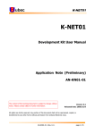
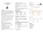
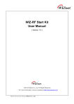
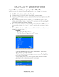
VOLTEK SC 6020 Kit User’s Manual
OPERATION
1.Fit the aerials provided to both receiver & Cameras. Plug in the power transformer (9V/500mA) to the
DC socket of the receiver. When power is applied the red power indicator light will light up.
2.Connect the yellow & white Phono plugs of the A/V cable to the yellow (video) & white (audio) sockets
on the receiver and the other end either directly to the Monitor or Recorder or by the use of the Scart
adaptor provided. Check the switches on the receiver are set as fig 1 to view the receiver output select the
AV Channel on the Monitor/Recorder.
3. Connect the power transformer (12V/1A) to the camera which will be marked CH1.This should allow
you to clearly view the Camera if any interference is present please refer to NOTES
4.In case of any interference with any other wireless devices the channel settings are as follows:
CH1: 2410MHZ CH2: 2430MHZ CH3: 2450MHZ CH4: 2470MHZ.
5. If more than 1 Camera is required you can add to the system by Purchasing up to 3 additional Camera
Each Camera must be set to a separate Channel number (they will be marked either by CH2, 3 or 4) &
that Channel must also be set on the Receiver as shown in Fig 2
Fig 1
Fig 2
NOTES
1.Use within a building or metal obstacles in transmission course may slightly affect the image quality
adjustment to the Camera position or aerial alignment may cure this.
2.It’s normal for the product to slightly warm up during operation.
3. If pointed at direct sunlight a slight redness will be detected in the picture use the sunshield to remove
any redness by moving it forward and angle the Camera down
4. All items come with a 12 Months parts warranty
5. Please contact Voltek on 0906 6191133* on our technical help line if required.
FUNCTION
. Suitable for monitoring children, older relatives, residents, offices, shops and factories, sited either inside
or out.
STANDARD ACCESSORIES
No.
Name
Unit
Amount
1
Power Transformer
Piece
2
2
Day night Camera
Piece
1
3
A/V Cable
Set
1
4
Scart Adaptor
Piece
1
SPECIFICATIONS
Imaging Sensor
CMOS Total Pixels
Inch
1/4” CCD
512×582 PAL
Pixels
Pixel Dimensions
µm
9.2×7.2
Minimum Illumination
Lux
0 Lux/F2.0
Horizontal Resolution
TV Line
420
White Balance Mode
White Balance Range
AWB (Zero Color Rolling)
ºK
3,200~10,000
Gain Control
AGC
S/N Ratio
dB
48(Min)
Electronic Shutter
Sec
1/100~1/100,000 Sec
Frequency
MHz
Operation Current
MA
2410-2483
4CH
Camera/TX: 300
Receiver: 350
Operating Temperature
ºC
-20~+50
Storage Temperature
ºC
-40~+85
Operating Humidity
RH
85%
Dimensions (W×L×H)
mm
Camera/Transmitter 118x55x55
Receiver 123×80×22
Weight
g
Camera/Transmitter: 350
Receiver: 138
Unobstructed Effective Range
Indoor: 20-50
m
Outdoor: 100-150
39c Churchill Way, Lomeshaye Ind. Est., Nelson, Lancashire. BB9 6RT, England
Tel (01282) 695 500 Fax (01282) 695 511 International (+44 1282)
Email: [email protected]
Website www.voltek.co.uk
*Help line calls cost 60p/minute. Open 9am to 5pm, Mon to Fri.
Voltek reserves the right to change any product or specification without notice.