1
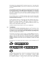
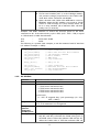
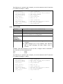
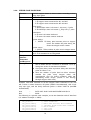
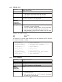
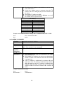
● ● ● On forward condition, indicator LED will also blink. On forward condition, Mn1 (n is the H-Bridge number) will produce voltage proportional to the PWM value while Mn2 will be connected with MGND. Motor direction and PWM value will not be saved in EEPROM. When the SPC module is powered on, PWM values of each H-bridge is 0 (zero) and the motor will be in a stop condition (all-4 indicator LEDs will blink faintly every 2 seconds). Example with UART interface to control the forward speed of DC motor connected to M1. If the desired duty cycle is 50% (0.5 * 255 = 128) or equal to 128 decimal or 0x80 hexadecimal: User SPC : : 0x30 0x01 0x80 0x06 The following is a pseudo code example, to use this command with I2C interface (I2C address example = 0xE0): i2c_start(); i2c_write(0xE0); i2c_write(0x30); i2c_write(0x01); i2c_write(0x80); i2c_stop(); // // // // // // Start Condition Write SPC Low Cost Motor module “DC Forward” command Motor number PWM value Stop Condition delay_us(10); // delay 10 us i2c_start(); i2c_write(0xE1); temp = i2c_read(0); i2c_stop(); // // // // Start Condition Read SPC Low Cost Motor module Data Acknowledgment Stop Condition 3.3.2. DC REVERSE Function Command Parameter Response Delay between Command and Response Description Controls DC motor reverse rotation 0x31 <Motor number> 1 DC motor connected to M1 2 DC motor connected to M2 3 DC motor connected to M3 4 DC motor connected to M4 <pwm level> 0 - 255 assigned duty cycle percentage (0 = 0%; 255 = 100%) 0x06 if command is recognized 0x15 if command is not recognized 10 µs ● Indicator LED light intensity for each H-Bridge (M1, M2, M3, and M4) will match the PWM value given. If the PWM value is 0 then the indicator LED will turn off. When the PWM value is 255 then indicator LED will 9