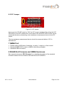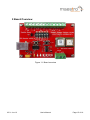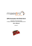
1
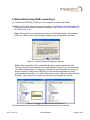
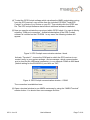
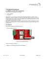
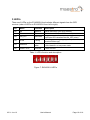
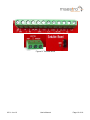
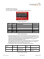
GPS Evaluation Kit EVA2035-H A Description of the Evaluation Board for Maestro’s GPS Antenna Receiver Module A2035-H User’s Manual Version 0.3 Revision History Rev. 0.1 0.2 0.3 Date 07-08-11 09-13-11 06-21-12 mm-dd-yy Written by Checked by Approval by V0.3– Jun-12 Description Initial Draft Updated EVA2035-H pictures Add description of the Port Selection& terminal block Name Happy wen Sam Law, Matthieu Frank Tang, Calvin Yau User’s Manual Date 06-21-12 06-21-12 06-21-12 Signature HW S L,M F T,C Y Page 2 of 18 Disclaimer THIS DOCUMENT CONTAINS PROPRIETARY INFORMATION OF MAESTRO WIRELESS SOLUTIONS LIMITED. IT MAY NOT BE COPIED OR TRANSMITTED BY ANY MEANS, PASSED TO OTHERS, OR STORED IN ANY RETRIEVAL SYSTEM OR MEDIA, WITHOUT PRIOR CONSENT OF MAESTRO OR ITS AUTHORIZED AGENTS. THE INFORMATION IN THIS DOCUMENT IS, TO THE BEST OF OUR KNOWLEDGE, ENTIRELY CORRECT. HOWEVER, MAESTRO CAN NEITHER ACCEPT LIABILITY FOR ANY INACCURACIES, OR THE CONSEQUENCES THEREOF, NOR FOR ANY LIABILITY ARISING FROM THE USE OR APPLICATION OF ANY CIRCUIT, PRODUCT, OR EXAMPLE SHOWN IN THE DOCUMENT. THE PRODUCT (HARD- AND SOFTWARE) DESCRIBED IN THIS DOCUMENTATION IS NOT AUTHORIZED FOR USE IN LIFE SUPPORT DEVICES OR SYSTEMS WITHOUT THE EXPRESS WRITTEN APPROVAL OF MAESTRO. THIS DOCUMENT MAY PROVIDE LINKS TO OTHER WORLD WIDE WEB SITES OR RESOURCES. BECAUSE MAESTRO HAS NO CONTROL OVER SUCH SITES AND RESOURCES, MAESTRO SHALL NOT BE RESPONSIBLE FOR THE AVAILABILITY OF SUCH EXTERNAL SITES OR RESOURCES, AND DOES NOT ENDORSE AND IS NOT RESPONSIBLE OR LIABLE FOR ANY CONTENT, ADVERTISING, PRODUCTS, OR OTHER MATERIALS ON OR AVAILABLE FROM SUCH SITES OR RESOURCES. MAESTRO SHALL NOT BE RESPONSIBLE OR LIABLE, DIRECTLY OR INDIRECTLY, FOR ANY DAMAGE OR LOSS CAUSED OR ALLEGED TO BE CAUSED BY OR IN CONNECTION WITH USE OF OR RELIANCE ON ANY SUCH CONTENT, GOODS OR SERVICES AVAILABLE ON OR THROUGH ANY SUCH SITE OR RESOURCE. MAESTRO RESERVES THE RIGHT TO CHANGE, MODIFY, OR IMPROVE THIS DOCUMENT OR THE PRODUCT DESCRIBED HEREIN, AS SEEN FIT BY MAESTRO WITHOUT FURTHER NOTICE. V0.3– Jun-12 User’s Manual Page 3 of 18 Table of Contents 1 Introduction ........................................................................................................ 5 1.1 Purpose............................................................................................................. 5 1.2 Contents............................................................................................................ 5 2 Handling Precautions ........................................................................................ 5 3 Quick Start (using USB connection) ................................................................ 6 4 On-Board Peripherals ........................................................................................ 9 4.1 RESET and ON_OFF Push-Button ................................................................... 9 4.2 Antenna............................................................................................................. 9 5 LED’s ................................................................................................................. 10 6 Design-in Support ............................................................................................ 11 6.1 Terminal Block ................................................................................................ 11 6.2 DIP Switch Settings......................................................................................... 13 6.3 ICC Jumper ..................................................................................................... 14 7 NMEA Port ........................................................................................................ 14 8 EVA2035-H Firmware and NMEA Sentences ................................................. 14 9 Board Overview ................................................................................................ 15 10 Board Schematics .......................................................................................... 16 11 Related Information ....................................................................................... 17 11.1 Contact.......................................................................................................... 17 11.2 Related Documents....................................................................................... 17 11.3 Related Tools ................................................................................................ 17 12 List of Figures ................................................................................................ 18 13 List of Tables .................................................................................................. 18 V0.3– Jun-12 User’s Manual Page 4 of 18 1 Introduction 1.1 Purpose The GPS Evaluation Kit EVA2035-H allows an easy evaluation of Maestro’s GPS antenna receiver module A2035-H by offering quick access to the ports of the module. The EVA2035-H serves three major purposes: As a demonstration package of the module’s capabilities Powering the A2035-H GPS receiver module via the USB connector with sufficient view to the sky will result in an NMEA output with position information. As an example how to integrate the module into a system The schematic in chapter “10 Board Schematics” is a basic example of how to integrate the GPS module into an application or system. To support an easy temporary design in The signals provided on the Evaluation Kit allow direct integration into a surrounding system making it an ideal development tool. The firmware provided on the A2035-H delivered with the EVA2035-H is identical to the standard firmware delivered on single A2035-H GPS antenna receiver modules. 1.2 Contents The EVA2035-H includes the following components: Demonstration board (labeled EVA2035-H) USB cable to connect to your PC CD with complete documentation and Maestro’s GPS Cockpit software Please check your package for completeness and connect the components properly. 2 Handling Precautions The EVA2035-H contains components that are sensitive to electrostatic discharge (ESD). Please handle with appropriate care. V0.3– Jun-12 User’s Manual Page 5 of 18 3 Quick Start (using USB connection) (1) Connect the EVA2035-H with your PC using the included USB cable. (2) When the PC asks for drivers select the folder “Tools\Drivers” on the included CD ROM. Note that two drivers need to be installed, the EVA2035-H FTDI driver and the USB serial driver. Note: During the driver installation process your Windows system will probably notify you, that the driver did not pass Windows logo testing with a warning: Figure 1: Windows driver installation warning Note: After successful driver installation Windows might interpret the data coming over the serial interface as a serial ballpoint mouse! Your mouse pointer can start jumping around. To stop this, disable the according device using your device manager. Leave the EVA2035-H kit connected and press and keep pressing the reset button. You will find the device under “Mice and other pointing devices”. Use a right click to open the sub-menu and disable the device. Update Driver Disable Uninstall Scan for hardware changes Properties Figure 2: Disabling of Microsoft Serial BallPoint (3) Assure that the on-module GPS antenna has a good view to the sky! V0.3– Jun-12 User’s Manual Page 6 of 18 (4) To start the GPS Cockpit software which visualizes the NMEA output data coming from the GPS receiver, copy all files from the included CD ROM “Tools/GPS Cockpit” to a folder of you choice on your PC. Then double click the GPSC.exe file. The GPS cockpit software starts without additional software installation. (5) Now you need to activate the correct port within GPS Cockpit. You can do this by selecting “COM port connection”. A detailed description of the GPS Cockpit software is included on the CD ROM. In any case, the following window will appear: Figure 3: GPS Cockpit communication window - blank Activate “Terminal 1”, choose the COM port to which the GPS receiver is connected (verify in your system settings - device manager, which communication port is used for this USB serial connection), in our example COM2 at 4800 baud (default setting for the EVA2035-H), and click on “OK”: Figure 4: GPS Cockpit communication window – COM2 The connection is established now. (6) Open a terminal window to see NMEA sentences by using the “NMEA Terminal” window button. You should then see messages like this: V0.3– Jun-12 User’s Manual Page 7 of 18 Figure 5: GPS Cockpit NMEA terminal with NMEA data Now you can start using all the other windows and features of GPS Cockpit. Please refer also to the GPS Cockpit manual and the online help within GPS Cockpit. V0.3– Jun-12 User’s Manual Page 8 of 18 4 On-Board Peripherals 4.1 RESET and ON_OFF Push-Button The EVA2035-H holds two push-buttons: nRST (RESET) ON_OFF After power on by pushing the “ON” button will start the A2035-H module. This is absolutely necessary to get the module going. The “ON” button must be used as well in other cases, e.g. in order to request a position when in SiRFawareTM state or to go to hibernate mode and wake up again. The “nRST” button is used to get a full reset of the GPS module. All parameters are stored in non-volatile memory. After pushing this button the module starts again from the beginning. 4.2 Antenna The A2035-H supports one antenna input: The on-module antenna. On-module antenna Figure 6: On-module antenna Further information is given in Maestro’s GPS Receiver A2035-H User Manual V0.3– Jun-12 User’s Manual Page 9 of 18 5 LED’s There are 6 LEDs on the EVA2035-H that indicate different signals from the GPS receiver (order of LED’s on EVA2035-H from left to right): LED Name Function LD2 LD1 RX TX Receive Transmit LD4 ON_OFF LD3 1PPS LD4 WAKEUP LD6 Power / VCC Description Serial data traffic (into GPS receiver) Serial data traffic (from GPS receiver) Toggle hibernate mode / position request during PTF Hibernate cycle (the LED visualizes the ON_OFF pulse) 1PPS signal at rising edge (1 pulse per second, Timing duration 500ms typ.) Operational HIGH: Full operation state LOW: Module in a low power mode POWER Power on LED Table 1: LED’s function and description Figure 7: EVA2035-H LED’s V0.3– Jun-12 User’s Manual Page 10 of 18 6 Design-in Support The EVA2035-H demo board offers the possibility to implement the A2035-H GPS receiver module temporarily into your design by using the terminal block with 15 connections & a pad of 3V3. To operate the EVA2035-H via this terminal block, please check “Table 3: Switch settings”. Please note: VCC power input is not protected against reversed polarity External supply has to be within the range of 3.3 to 3.6 VDC 6.1 Terminal Block The terminal block offers direct access to the A2035-H GPS receiver pins. Pin 1 2 3 4 5 6 7 8 9 10 11 12 13 14 15 Port GND TX, SPI data out pin when module works in SPI mode RX, SPI data in pin when module works in SPI mode ON_OFF 1PPS (Pulse Per Second) G_6 (GPIO6), SPI clock pin when module works in SPI mode G_7 (GPIO7), SPI chip select pin when module works in SPI mode EXTint I2C_DIO I2C_CLK 1V8(Output) G_4 nRST (reset) BOOTSEL WAKEUP(operational mode) Table 2: Terminal block description V0.3– Jun-12 User’s Manual Page 11 of 18 Figure 8: Terminal block V0.3– Jun-12 User’s Manual Page 12 of 18 6.2 DIP Switch Settings The following picture shows the DIP switches of the EVA2035-H. Figure 9: DIP switches Switch Function S1 S2 S3 S4 S5 S6 S7 S8 VCC TX RX ON_OFF 1PPS GPIO6 GPIO7 BOOTSEL Operation via USB connector (default settings) ON ON ON ON ON ON OFF OFF Operation via terminal block OFF OFF OFF OFF OFF ON(*2) OFF(*2) OFF (*1) Table 3: Switch settings *1: The BOOT switch can be set to flash Firmware to the A2035-H GPS receiver. Switch the BOOTSEL switch to “ON”, press and release the nRST button. The A2035-H is now waiting to receive new firmware data via UART. For the detail description &Firmware upgrade procedure,please refer to” Firmware upgrading for GPS Modules”application note. After upgrading the firmware switch the BOOTSEL switch to “OFF” and press and release the nRST button for restarting normal GPS receiver operation. Related software tool and documentation: SIRF_Flash *2: Port Selection, Table 4 shows GPIO strapping for port selection. Host Interface Type Slave SPI GPIO7 Level High UART High GPIO7 Pull OPEN Weak internal pull up OPEN Weak internal pull up GPIO6 Level LOW HIGH GPIO6 Pull OPEN Weak internal pull down Strong external pull-up Table 4: Switch settings V0.3– Jun-12 User’s Manual Page 13 of 18 6.3 ICC Jumper Figure 10: ICC jumper As long as the VCC DIP switch is “ON” the ICC jumper is bridged. By putting the VCC DIP switch to the OFF position the current draw of the A2035-H GPS receiver can be measured directly by connecting a low resistance measurement device to the ICC jumper. The low resistance measurement device should be connected before VCC is switched off! 7 NMEA Port Default setting: 4800 baud, 8 data bits, no parity, 1 stop bit, no flow control! Standard NMEA-0183 output on NMEA, baud rate selectable. Standard USB connectors 8 EVA2035-H Firmware and NMEA Sentences See separate document GPS Firmware for a detailed description of the standard firmware loaded onto the modules delivered with the EVA2035-H. V0.3– Jun-12 User’s Manual Page 14 of 18 9 Board Overview Figure 11: Board overview V0.3– Jun-12 User’s Manual Page 15 of 18 10 Board Schematics Figure 12: EVA2035-H board schematics V0.3– Jun-12 User’s Manual Page 16 of 18 11 Related Information 11.1 Contact This manual was created with due diligence. We hope that it will be helpful to the user to get the most out of the GPS module. Inputs regarding errors or mistaken verbalizations and comments or proposals to Maestro, HongKong, for further improvements are highly appreciated. Maestro Wireless Solutions Limited Add:Unit 3603-09,36/F.,118 Connaught Road West,HK Main Line: (852) 28690688 Fax: (852)25254701 [email protected] www.maestro-wireless.com 11.2 Related Documents GPS Receiver A2035-H (Maestro) Firmware upgrading for GPS Modules (Maestro) 11.3 Related Tools GPS Cockpit (Maestro) SiRFLive (SiRF) SiRF Flash(SiRF) V0.3– Jun-12 User’s Manual Page 17 of 18 12 List of Figures Figure 1: Windows driver installation warning .......................................................... 6 Figure 2: Disabling of Microsoft Serial BallPoint ...................................................... 6 Figure 3: GPS Cockpit communication window - blank ............................................ 7 Figure 4: GPS Cockpit communication window – COM2 ......................................... 7 Figure 5: GPS Cockpit NMEA terminal with NMEA data .......................................... 8 Figure 6: On-module antenna .................................................................................. 9 Figure 7: EVA2035-H LED’s ...................................................................................10 Figure 8: Terminal block..........................................................................................12 Figure 9: DIP switches ............................................................................................13 Figure 10: ICC jumper .............................................................................................14 Figure 11: Board overview ......................................................................................15 Figure 12: EVA2035-H board schematics ...............................................................16 13 List of Tables Table 1: LED’s function and description ..................................................................10 Table 2: Terminal block description.........................................................................11 Table 3: Switch settings ..........................................................................................13 Table 4: Switch settings ..........................................................................................13 V0.3– Jun-12 User’s Manual Page 18 of 18