1
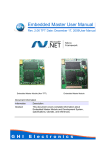
Artisan Technology Group is your source for quality new and certified-used/pre-owned equipment • FAST SHIPPING AND DELIVERY • TENS OF THOUSANDS OF IN-STOCK ITEMS • EQUIPMENT DEMOS • HUNDREDS OF MANUFACTURERS SUPPORTED • LEASING/MONTHLY RENTALS • ITAR CERTIFIED SECURE ASSET SOLUTIONS SERVICE CENTER REPAIRS Experienced engineers and technicians on staff at our full-service, in-house repair center WE BUY USED EQUIPMENT Sell your excess, underutilized, and idle used equipment We also offer credit for buy-backs and trade-ins www.artisantg.com/WeBuyEquipment InstraView REMOTE INSPECTION LOOKING FOR MORE INFORMATION? Visit us on the web at www.artisantg.com for more information on price quotations, drivers, technical specifications, manuals, and documentation SM Remotely inspect equipment before purchasing with our interactive website at www.instraview.com Contact us: (888) 88-SOURCE | [email protected] | www.artisantg.com mikro elektronik gmbh nürnberg M69 Quadruple RS232 Interface M-Module 20M069-00 E1 User Manual Wiesentalstr. 40 90419 Nürnberg Tel.: + 9 11 / 99 33 5-0 Fax: + 9 11 / 99 33 5-99 e-mail: [email protected] WWW: http://www.men.de Artisan Technology Group - Quality Instrumentation ... Guaranteed | (888) 88-SOURCE | www.artisantg.com M69 - Quadruple RS232 Interface M69 - Quadruple RS232 Interface The M69 allows use of four very flexible, optically isolated, asynchronous receivers/ transmitters with modem control lines on a single M-Module. 12 bytes of FIFO for each transmitter and each receiver reduce the interrupt load for the host CPU and prevent loss of receive data. The M69 is based on one CL-CD1400 device with four full-duplex serial channels. With optional special character processing capabilities, it is especially suited for UNIX-like applications. Its high throughput, low power consumption and high-level integration allow for system designs with minimum part-count, maximum performance and maximum reliability. Technical Data 4 RS232 Interfaces: • 2 with 4 lines (2 modem control lines) • 2 with 6 lines (4 modem control lines) • all 4 channels optically isolated from the system and from each other CL-CD1400 Communication Engine: • software programmable serial data rates up to 135kbits/s full duplex on 4 channels • 12 bytes of FIFO for each transmitter/receiver • GOOD DATA interrupts eliminate the need for character status check • independent bit rate selections for transmit and receive on each channel • automatic flow control modes for serial channels: - XON/XOFF - RTS/CTS - DTR/DSR • special character processing, optionally handled by CL-CD1400 • line break detection (start and end) and generation • insertion of transmit delays in data stream • one timer per channel for receiver data timeout interrupt • 5..8 bits per character plus parity • parity mode: odd, even, no or forced • stop bits: 1, 1.5 or 2 Electrical Specifications: • isolation voltage: 500V DC • supply voltage/power consumption: +5V (4.85V..5.25V) @ 700mA typ. • MTBF: tbd. Mechanical Specifications: • dimensions: conform to M-Module Standard • weight: 92g Environmental Specifications: • temperature range (operation): 0..60°C (industrial temperature range on request) • temperature range (storage): -25..70°C • relative humidity range (operation): max. 95% without condensation • relative humidity range (storage): max. 95% without condensation • altitude: -300m to + 3,000m • shock: 15g/0.33ms, 6g/6ms • vibration: 1g/5..2,000Hz Safety: • PCB manufactured with a flammability rating of 94V-0 by UL recognized manufacturers EMC: Peripheral Connections: • via front panel on a shielded 25-pin D-Sub connector (female) • via base board connector M-Module Characteristics: • tested according to IEC1000-4-2 (ESD) and IEC1000-4-4 (burst) with regard to CE conformity Software Support: • OS-9 SPF driver • WindowsNT driver • A08, D08, INTA, IDENT MEN Mikro Elektronik GmbH M69HW/E1 Artisan Technology Group - Quality Instrumentation ... Guaranteed | (888) 88-SOURCE | www.artisantg.com 2 Block Diagram Block Diagram RS232 User-Configurable Channel 0 Serial User-Configurable Channel 1 Serial CL-CD1400 Firmware ROM User-Configurable Channel 2 Serial D0..D7 RISC Processor Host Bus Interface Logic M-Module Interface A1..A7 RAM User-Configurable Channel 3 Serial Control M-Module ID EEPROM Ordering Information Standard Hardware 04M069-00 M69 hardware 20M069-00 M69 user manual Standard Software 13M069-01 OS-9 SPF driver software (object code) 21M069-00 M69 OS-9 driver manual 13M069-70 WindowsNT driver software incl. user manual MEN Mikro Elektronik GmbH M69HW/E1 Artisan Technology Group - Quality Instrumentation ... Guaranteed | (888) 88-SOURCE | www.artisantg.com 3 Contents Contents 1 Getting Started . . . . . . . . . . . . . . . . . . . . . . . . . . . . . . . . . . . . . . . . . . . . . . . . . . . . . . . . . . . . . . . . . . . . . . . . . 6 1.1 Installation Check List . . . . . . . . . . . . . . . . . . . . . . . . . . . . . . . . . . . . . . . . . . . . . . . . . . . . . . . . . . . . . 6 1.2 Power Supply . . . . . . . . . . . . . . . . . . . . . . . . . . . . . . . . . . . . . . . . . . . . . . . . . . . . . . . . . . . . . . . . . . . . 6 2 Connection of the Module . . . . . . . . . . . . . . . . . . . . . . . . . . . . . . . . . . . . . . . . . . . . . . . . . . . . . . . . . . . . . . . . 6 2.1 Peripheral Interfaces. . . . . . . . . . . . . . . . . . . . . . . . . . . . . . . . . . . . . . . . . . . . . . . . . . . . . . . . . . . . . . . 6 2.2 Host Interface . . . . . . . . . . . . . . . . . . . . . . . . . . . . . . . . . . . . . . . . . . . . . . . . . . . . . . . . . . . . . . . . . . . . 7 3 Address Organization . . . . . . . . . . . . . . . . . . . . . . . . . . . . . . . . . . . . . . . . . . . . . . . . . . . . . . . . . . . . . . . . . . . . 8 3.1 Address Organization of the M-Module . . . . . . . . . . . . . . . . . . . . . . . . . . . . . . . . . . . . . . . . . . . . . . . 8 3.2 Address Organization of the CL-CD1400 . . . . . . . . . . . . . . . . . . . . . . . . . . . . . . . . . . . . . . . . . . . . . . 8 4 Functional Description . . . . . . . . . . . . . . . . . . . . . . . . . . . . . . . . . . . . . . . . . . . . . . . . . . . . . . . . . . . . . . . . . . 10 4.1 The CL-CD1400 Communications Engine . . . . . . . . . . . . . . . . . . . . . . . . . . . . . . . . . . . . . . . . . . . . 10 4.2 Interrupts . . . . . . . . . . . . . . . . . . . . . . . . . . . . . . . . . . . . . . . . . . . . . . . . . . . . . . . . . . . . . . . . . . . . . . 10 4.3 M-Module Identification . . . . . . . . . . . . . . . . . . . . . . . . . . . . . . . . . . . . . . . . . . . . . . . . . . . . . . . . . . 11 5 Appendix . . . . . . . . . . . . . . . . . . . . . . . . . . . . . . . . . . . . . . . . . . . . . . . . . . . . . . . . . . . . . . . . . . . . . . . . . . . . . 11 5.1 Literature . . . . . . . . . . . . . . . . . . . . . . . . . . . . . . . . . . . . . . . . . . . . . . . . . . . . . . . . . . . . . . . . . . . . . . 11 5.2 Module Revisions. . . . . . . . . . . . . . . . . . . . . . . . . . . . . . . . . . . . . . . . . . . . . . . . . . . . . . . . . . . . . . . . 11 5.3 Configuration Plan . . . . . . . . . . . . . . . . . . . . . . . . . . . . . . . . . . . . . . . . . . . . . . . . . . . . . . . . . . . . . . . 12 Figures Figure 1: Configuration Plan of M69 Rev. 00 . . . . . . . . . . . . . . . . . . . . . . . . . . . . . . . . . . . . . . . . . . 12 Tables Table 1: Table 2: Table 3: Table 4: Table 5: Table 6: Table 7: Table 8: Pin Assignment of the female 25-Pin D-Sub Connector . . . . . . . . . . . . . . . . . . . . . . . . . . . 6 Female 24-Pin Connector. . . . . . . . . . . . . . . . . . . . . . . . . . . . . . . . . . . . . . . . . . . . . . . . . . . 7 Signal Correspondence between 24-Pin Module and 96-pin Base Board Connector . . . . . 7 Signal Mnemonics . . . . . . . . . . . . . . . . . . . . . . . . . . . . . . . . . . . . . . . . . . . . . . . . . . . . . . . . 7 Supported Pins of male 60-Pin Connector on Base Board. . . . . . . . . . . . . . . . . . . . . . . . . . 7 Address Map . . . . . . . . . . . . . . . . . . . . . . . . . . . . . . . . . . . . . . . . . . . . . . . . . . . . . . . . . . . . 8 CL-CD1400 Registers in Alphanumerical Order. . . . . . . . . . . . . . . . . . . . . . . . . . . . . . . . . 8 Table of Revisions . . . . . . . . . . . . . . . . . . . . . . . . . . . . . . . . . . . . . . . . . . . . . . . . . . . . . . . 11 MEN Mikro Elektronik GmbH M69HW/E1 Artisan Technology Group - Quality Instrumentation ... Guaranteed | (888) 88-SOURCE | www.artisantg.com 4 About the Manual About the Manual This manual describes the hardware functions of the M-Module, connection of peripheral devices and integration into a system. It also provides additional information for special applications and configurations of the board. The manual does not include detailed information on individual components (data sheets etc.). A list of literature is given in the appendix. All circuit diagrams included in this manual are intended for information only and are therefore subject to change without notice. History Edition E1 Description First edition Technical Content Jonny Speckner Date of Issue April 29,1998 Conventions This sign marks important notes or warnings concerning proper functionality of the product described in this manual. You should read them in any case. 0xFF Hexadecimal numbers are preceded by "0x", which is the usual C-language convention. /IRQ Signal names preceded by a slash ("/") indicate that this signal is either active low or that it becomes active at a falling edge. in/out Signal directions in signal mnemonics tables generally refer to the corresponding board or component, "in" meaning "to the board or component", "out" meaning "coming from it". All brand or product names are trademarks or registered trademarks of their respective holders. Information in this document has been carefully checked and is believed to be accurate as of the date of publication; however, no responsibility is assumed for inaccuracies. MEN will not be liable for any consequential or incidental damages arising from reliance on the accuracy of this document. The information contained herein is subject to change without notice. Copyright © 1998 MEN Mikro Elektronik GmbH. All rights reserved. MEN Mikro Elektronik GmbH M69HW/E1 Artisan Technology Group - Quality Instrumentation ... Guaranteed | (888) 88-SOURCE | www.artisantg.com 5 Getting Started 1 Getting Started 2 Connection of the Module This chapter will give an overview of the module and some hints for first installation in a system as a "check list". 2.1 Peripheral Interfaces 1.1 There are peripherals: Installation Check List You can use the following "check list" to install the M-Module on a carrier board for the first time and to test proper functioning of the module. The M-Module is completely trimmed on delivery. ; Power-down the system. ; Install the M-Module carrier board in your system without the M-Module. ; Power-up the system. ; Test the carrier board. ; If O.K., power-down the system and remove the carrier board. ; Install the module in slot 0 of the carrier board. two When a base board with a 96-pin DIN 41612 PCB connection is used for peripheral signals (for example a 6U VMEbus base board), these are fed to the module through the female 24-pin connector. You can connect up to four 21-pin connectors to the 96pin connector (cf. base board manual). When these connectors are used, for each module three pins of the DIN 41612 PCB connector cannot be used. The pin numbers for the 96-pin connector shown below are valid for module slot number 3. If other module slots (2, 1 or 0) are used, the value 8, 16 or 24 must be added as appropriate. Table 1: Pin Assignment of the female 25-Pin D-Sub Connector 1 14 ; Load a suitable debugger. ; Read a word from the base address plus 0x80. ; If a bus error is occurring now, the module is not plugged properly. ; Reading from the above address should yield the value 0x4646 or 0x4747 (firmware revision code of CL-CD1400). ; Observe the installation manuals for operating system dependent software. 1.2 Power Supply connecting • connection via the base board. ; Insert the base board into the system again. Note: Operation and functionality of the M69 M-Module depend heavily on software support. MEN supplies standard software for various operating systems. If you use MEN software, please refer to the software manual for a description of supported functions. If you don’t use MEN software, please refer to the data sheet of the CL-CD1400 (see Chapter 5.1 Literature on page 11) for detailed information on the device. for • connection via 25-pin D-Sub connector or ; Initially, do not change any jumpers or switches. ; Power-up the system. possibilities 13 25 1 CTS0 14 RXD0 2 TXD0 15 DTR0 3 GND0 16 CTS1 4 RXD1 17 TXD1 5 DTR1 18 GND1 6 CTS2 19 RXD2 7 TXD2 20 DTR2 8 GND2 21 CTS3 9 RXD3 22 TXD3 10 DTR3 23 GND3 11 DSR3 24 RTS3 12 DSR2 25 RTS2 13 - Connector types: • according to DIN41652/MIL-C-24308, with thread bolt UNC 4-40 • mating connector: 25-pin D-Sub plug according to DIN41652/MIL-C-24308, available for ribbon cable (insulation piercing connection), handsoldering connection or crimp connection Power supply to the logic part is done via the base board. The necessary voltage is +5V. MEN Mikro Elektronik GmbH M69HW/E1 Artisan Technology Group - Quality Instrumentation ... Guaranteed | (888) 88-SOURCE | www.artisantg.com 6 Connection of the Module Table 2: 1 2 4 3 24 2.2 Female 24-Pin Connector 23 2 RXD0 1 CTS0 4 DTR0 3 TXD0 6 CTS1 5 GND0 8 TXD1 7 RXD1 10 GND1 9 DTR1 12 RXD2 11 CTS2 14 DTR2 13 TXD2 16 CTS3 15 GND2 18 TXD3 17 RXD3 20 GND3 19 DTR3 22 - 21 - 24 - 23 - Host Interface The M69 module supports the following signals of the male 60-pin base board interface connector: Note: Only two rows - A and B - of the 60-pin connector are mounted on the M69! Connector types: • three 20-pin receptacles, high-precision, 2.54mm pitch, for square pins ∅ 0.635mm gold, 6.9mm height • mating connector: three 20-pin plugs, 2.54mm pitch, square pins ∅ 0.635mm gold Table 5: Supported Pins of male 60-Pin Connector on Base Board A B C 1 /CS GND - 1 2 A01 +5V - 2 3 A02 - - 4 A03 - - 5 A04 GND - 6 A05 - - 7 A06 - - 8 A07 GND - 9 - D00 - 10 - D01 - 11 - D02 - 12 - D03 - 13 - D04 - 14 - D05 - 15 - D06 - 16 - D07 - 17 - /DS0 - 18 /DTACK /WRITE - 19 - /IRQ - 20 /RESET SYSCLK - Connector types: • two 12-pin receptacles, high-precision, 2.54mm pitch, for square pins ∅ 0.635mm gold, 6.9mm height A B C • mating connector: two 12-pin plugs, 2.54mm pitch, square pins ∅ 0.635mm gold Table 3: C B A 1 8 Table 4: Signal Correspondence between 24Pin Module and 96-pin Base Board Connector C B A 1 TXD0 RXD0 CTS0 2 CTS1 GND0 DTR0 3 DTR1 TXD1 RXD1 4 RXD2 CTS2 GND1 5 GND2 DTR2 TXD2 6 TXD3 RXD3 CTS3 7 - GND3 DTR3 8 - - - Signal Mnemonics Signal Direction Function CTS in Clear To Send DSR in Data Set Ready (only channels 2 and 3) DTR out Data Terminal Ready GND - reference signal RTS out Request To Send (only channels 2 and 3) RXD in receive data line TXD out transmit data line 20 MEN Mikro Elektronik GmbH M69HW/E1 Artisan Technology Group - Quality Instrumentation ... Guaranteed | (888) 88-SOURCE | www.artisantg.com 7 Address Organization 3 Address Organization Table 6: Address Map Address When using the driver software supplied, you do not need to be familiar with the hardware of the M69 module in detail. However, familiarity with the address organization of the board is essential if you wish to write your own software for the module or do low-level development. Address Organization of the M-Module The 256-byte I/O area of the M69 module is hardware-mapped. The address at which individual functions can be addressed from the base board is computed from the base address of the module plus the address in the following table. Table 7: Name D7..D0 0x00..0xFD - CD1400 channels 0..3 (r/w) 0xFE - module identification (r/w) 3.2 3.1 D15..D8 Address Organization of the CL-CD1400 To calculate the internal register addresses of the CD1400 the address values of the data sheet must be multiplied by two (see table below). The following table gives the register set of the CD1400 in alphanumerical order. CL-CD1400 Registers in Alphanumerical Order Address Function Type CAR 0xD0 channel access register (r/w) G CCR 0x0A channel command register (r/w) C CCSR 0x16 channel control status register (r) C COR1 0x10 channel option register 1 (r/w) C COR2 0x12 channel option register 2 (r/w) C COR3 0x14 channel option register 3 (r/w) C COR4 0x3C channel option register 4 (r/w) C COR5 0x3E channel option register 5 (r/w) C EOSRR 0xC0 end of service request register (w) V GCR 0x96 global configuration register (r/w) G GFRCR 0x80 global firmware revision code register (r/w) G LIVR 0x30 local interrupt vector register (r/w) C LNC 0x48 lnext character (r/w) C MCOR1 0x2A modem change option register 1 (r/w) C MCOR2 0x2C modem change option register 2 (r/w) C MICR 0x8C modem interrupt channel register (r/w) G MIR 0xD2 modem interrupt register (r/w) G MISR 0x98 modem interrupt status register (r) V MIVR 0x82 modem interrupt vector register (r) V MSVR1 0xD8 modem signal value register 1 (r/w) C MSVR2 0xDA modem signal value register 2 (r/w) C PRP 0xFC prescaler period register (r/w) G PSVR 0xDE printer signal value register (r/w) C RBPR 0xF0 receive baud rate period register (r/w) C RCOR 0xF8 receive clock option register (r/w) C RDCR 0x1C received data count register (r) C RDSR 0xC4 receive data/status register (r) V MEN Mikro Elektronik GmbH M69HW/E1 Artisan Technology Group - Quality Instrumentation ... Guaranteed | (888) 88-SOURCE | www.artisantg.com 8 Address Organization Name Address Function Type RICR 0x88 receive interrupt channel register (r/w) G RIR 0xD6 receive interrupt register (r/w) G RIVR 0x86 receive interrupt vector register (r) V RTPR 0x42 receive time-out period register (r/w) C SCHR1 0x34 special character register 1 (r/w) C SCHR2 0x36 special character register 2 (r/w) C SCHR3 0x38 special character register 3 (r/w) C SCHR4 0x3A special character register 4 (r/w) C SCRH 0x46 special character range, high (r/w) C SCRL 0x44 special character range, low (r/w) C SRER 0x0C service request enable register (r/w) C SVRR 0xCE service request register (r) G TBPR 0xE4 transmit baud rate period register (r/w) C TCOR 0xEC transmit clock option register (r/w) C TDR 0xC6 transmit data register (w) V TICR 0x8A transmit interrupt channel register (r/w) G TIR 0xD4 transmit interrupt register (r/w) G TIVR 0x84 transmit interrupt vector register (r) V Note: register type abbreviations: G = global register V = virtual register C = per-channel register MEN Mikro Elektronik GmbH M69HW/E1 Artisan Technology Group - Quality Instrumentation ... Guaranteed | (888) 88-SOURCE | www.artisantg.com 9 Functional Description 4 Functional Description 4.1 The CL-CD1400 Communications Engine Overview The CL-CD1400 is a flexible asynchronous receiver/transmitter with four full-duplex serial channels, or three full-duplex channels and one highspeed bidirectional parallel channel (which cannot be used on the M69). With optional special-character processing capabilities, it is especially well-suited for UNIX applications. The CL-CD1400 is fabricated in an advanced CMOS process and operates on a system clock of up to 25MHz (16MHz used on the M69). Packaged in a 68-pin PLCC, its high throughput, low power consumption and high level of integration permit system designs with minimum part-count, maximum performance and reliability: a good choice for an M-Module. Registers All communication with the CL-CD1400 takes place through a large array of registers. Registers are considered one of three types: global, virtual and perchannel. Global registers affect all channels within the device. Per-channel registers pertain only to the channel being referenced. Global registers are always available for the host access. Access to the local registers of a particular channel requires selecting the register set of that channel. Virtual registers are only available to the host during the context of a service routine. There are four sets of per-channel registers, one for each channel. Selection of the register set is accomplished by writing the channel number (0 through 3) into the Channel Access Register (CAR). This causes a 'bank switch' action, allowing the registers of the selected channel to be accessed. At any given time, only the registers of a single channel are available. Once selected, this register set remains available until the CAR is changed by the host. The MPU is a true RISC processor. In addition to having a compact, efficient set of instructions, it has a 'windowed' architecture that allows it to handle one channel and its registers at once. Before starting any operation on a given channel, it loads an internal Index Register that forces all accesses to the appropriate register set. The Index Register becomes part of the internal address and permits direct addressing of the register. No address computation is needed to select the proper channel. 4.2 Interrupts From the host point of view, the CL-CD1400 operates in one of two modes: normal mode of operation and service request/acknowledge. The normal mode of operation allows the host to make changes and obtain current operation status on a global and per-channel basis. The Service Request/Acknowledge Mode is used when a particular channel needs service; it is used, for example, when a receive FIFO has reached its programmed threshold and requires emptying. A service request can only be responded after it has been placed in a service acknowledge 'context'. The term 'interrupt' is used as a general description of the method by which the device gains the attention of the host CPU. The external request is the activation of one of the SVCREQ* output pins, depending on whether the type of service needed is for receive, transmit or modem signal change. All six lines of the CL-CD1400 on the M69 are ORed together to generate the /IRQ line of the M-Module. The internal request includes a channel pointer that points to the channel requiring service. When the host service acknowledge begins, the pointer is loaded into the CAR, thus the request automatically services the proper channel. Interrupts of the module are in accordance with Mode a) of the M-Module Specification, i.e., the interrupt request is reset by software, but the M69 module itself is not able to supply a vector during the interrupt-acknowledge cycle. A detailed description of the host interface and the register programming is presented in the data sheet of the device. Device Architecture The CL-CD-1400 is a small computer system for sending and receiving serial and parallel data. It is comprised of a RISC processor (MPU), RAM, ROM, host bus interface logic, and serial data channels. It has special instructions and hardware that facilitate serial data manipulation. MEN Mikro Elektronik GmbH M69HW/E1 Artisan Technology Group - Quality Instrumentation ... Guaranteed | (888) 88-SOURCE | www.artisantg.com 10 Appendix 4.3 M-Module Identification The M69 module is supplied with an identification EEPROM in accordance with the M-Module standard. Access to M-Module address 0xFE will never meet the CL-CD1400 but the EEPROM register. M-Module Identification (0xFE) (r/w) 15..8 7..3 2 1 0 - - CS CLK DATA CS: 1 = chip-select for EEPROM (write) CLK: serial identification clock (write) DATA: identification data (read/write) 5 Appendix 5.1 Literature • M-Module Standard: ANSI/VITA 12-1996, M-Module Specification; VMEbus International Trade Association 7825 E. Gelding Dr., Ste. 104, Scottsdale, AZ 85260 WWW: http://www.vita.com • UXART CL-CD1400: CL-CD1400 Data Sheet Cirrus Logic, Inc., USA, 1992 WWW: http://www.cirrus.com 5.2 Module Revisions Table 8: Rev. 0.x Table of Revisions Comment first revision Restrictions none known MEN Mikro Elektronik GmbH M69HW/E1 Artisan Technology Group - Quality Instrumentation ... Guaranteed | (888) 88-SOURCE | www.artisantg.com 11 Appendix 5.3 Configuration Plan Figure 1: Configuration Plan of M69 Rev. 00 MEN Mikro Elektronik GmbH M69HW/E1 Artisan Technology Group - Quality Instrumentation ... Guaranteed | (888) 88-SOURCE | www.artisantg.com 12 You can request the circuit diagrams for the current revision of the product described in this manual by completely filling out and signing the following non-disclosure agreement. Please send the agreement to MEN by mail. We will send you the circuit diagrams along with a copy of the completely signed agreement by return mail. MEN reserves the right to refuse sending of confidential information for any reason that MEN may consider substantial. Non-Disclosure Agreement for Circuit Diagrams provided by MEN Mikro Elektronik GmbH between MEN Mikro Elektronik GmbH Neuwieder Straße 7 D-90411 Nürnberg (”MEN”) and ____________________ ____________________ ____________________ ____________________ (”Recipient”) We confirm the following Agreement: MEN Recipient Date: ______________________ Date: ______________________ Name: ______________________ Name: ______________________ Function: ______________________ Function: ______________________ Signature: Signature: ____________________________________ ____________________________________ The following Agreement is valid as of the date of MEN’s signature. 1HXZLHGHU6WUDH '1UQEHUJ 3KRQH )D[ (0DLOLQIR#PHQGH :::ZZZPHQGH Non-Disclosure Agreement for Circuit Diagrams page 1 of 2 ,62FHUWLILHG Artisan Technology Group - Quality Instrumentation ... Guaranteed | (888) 88-SOURCE | www.artisantg.com 1 Subject The subject of this Agreement is to protect all information contained in the circuit diagrams of the following product: Article Number:__________________ [filled out by recipient] MEN provides the recipient with the circuit diagrams requested through this Agreement only for information. 2 Responsibilities of MEN Information in the circuit diagrams has been carefully checked and is believed to be accurate as of the date of release; however, no responsibility is assumed for inaccuracies. MEN will not be liable for any consequential or incidental damages arising from reliance on the accuracy of the circuit diagrams. The information contained therein is subject to change without notice. 3 Responsibilities of Recipient The recipient, obtaining confidential information from MEN because of this Agreement, is obliged to protect this information. The recipient will not pass on the circuit diagrams or parts thereof to third parties, neither to individuals nor to companies or other organizations, without the written permission by MEN. The circuit diagrams may only be passed to employees who need to know their content. The recipient protects the confidential information obtained through the circuit diagrams in the same way as he protects his own confidential information of the same kind. 4 Violation of Agreement The recipient is liable for any damage arising from violation of one or several sections of this Agreement. MEN has a right to claim damages amounting to the damage caused, at least to DM 100,000. 5 Other Agreements MEN reserves the right to pass on its circuit diagrams to other business relations to the extent permitted by the Agreement. Neither MEN nor the recipient acquire licenses for the right of intellectual possession of the other party because of this Agreement. This Agreement does not result in any obligation of the parties to purchase services or products from the other party. 6 Validity of Agreement The period after which MEN agrees not to assert claims against the recipient with respect to the confidential information disclosed under this Agreement shall be _______ months [filled out by MEN]. (Not less than twenty-four (24) nor more than sixty (60) months.) 7 General If any provision of this Agreement is held to be invalid, such decision shall not affect the validity of the remaining provisions and such provision shall be reformed to and only to the extent necessary to make it effective and legal. This Agreement is only effective if signed by both parties. Amendments to this Agreement can be adopted only in writing. There are no supplementary oral agreements. This Agreement shall be governed by German Law. The court of jurisdiction shall be Nuremberg. 1HXZLHGHU6WUDH '1UQEHUJ 3KRQH )D[ (0DLOLQIR#PHQGH :::ZZZPHQGH Non-Disclosure Agreement for Circuit Diagrams page 2 of 2 ,62FHUWLILHG Artisan Technology Group - Quality Instrumentation ... Guaranteed | (888) 88-SOURCE | www.artisantg.com Fax Reply Who you are... Name __________________________ Phone No. __________________________ Company __________________________ Fax No. __________________________ Department __________________________ E-mail __________________________ Use our online forms at http://www.men.de What we can do for you... Product Support Manual Feedback Product Article No. __________________ Manual Article No. __________________ Revision __ __ . __ __ . __ __ Edition If the product is a mezzanine module: Carrier Article No. __________________ Revision __ __ . __ __ . __ __ • Technical Support • User Manuals E ___ Useful or awful? very useful QQQQQ totally awful Operating system Usage Q OS-9 Y I read the manual and decided to buy the related product. Q VxWorks Q WindowsNT Q other: ___________________________________ Y I read the manual when I got the product. Y I refer to the manual only when I have problems. Your problems/comments... 1HXZLHGHU6WUDH '1UQEHUJ 3KRQH )D[ (0DLOLQIR#PHQGH :::ZZZPHQGH ,62FHUWLILHG Artisan Technology Group - Quality Instrumentation ... Guaranteed | (888) 88-SOURCE | www.artisantg.com Artisan Technology Group is your source for quality new and certified-used/pre-owned equipment • FAST SHIPPING AND DELIVERY • TENS OF THOUSANDS OF IN-STOCK ITEMS • EQUIPMENT DEMOS • HUNDREDS OF MANUFACTURERS SUPPORTED • LEASING/MONTHLY RENTALS • ITAR CERTIFIED SECURE ASSET SOLUTIONS SERVICE CENTER REPAIRS Experienced engineers and technicians on staff at our full-service, in-house repair center WE BUY USED EQUIPMENT Sell your excess, underutilized, and idle used equipment We also offer credit for buy-backs and trade-ins www.artisantg.com/WeBuyEquipment InstraView REMOTE INSPECTION LOOKING FOR MORE INFORMATION? Visit us on the web at www.artisantg.com for more information on price quotations, drivers, technical specifications, manuals, and documentation SM Remotely inspect equipment before purchasing with our interactive website at www.instraview.com Contact us: (888) 88-SOURCE | [email protected] | www.artisantg.com