1
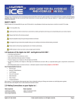
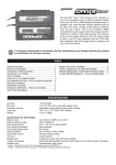
Pixie-20P™ Castle Creations™ By Programmable Sub Micro Digital Motor Control carefully cut through the insulation around the wire. Then the insulation should easily pull off the wire.) Attach the battery connector to the wires ENSURING THAT THE POLARITY (red wire to battery red wire, black wire to battery black wire) IS CORRECT, following the instructions for the battery connector. 1.0 Features of the Pixie-20P: • • • • • • • • • • • • • • • • Microprocessor controlled Low Resistance (.0027 ohms) High rate (2800 Hz) switching (PWM) Up to 20 Amps continuous current (with proper air flow) High Output (1.5amp) Battery Eliminator Circuit (BEC) provides power to receiver and servos - eliminates separate receiver battery Five – seven cells with four micro servos Eight cells with three micro servos Nine or ten cells with two micro servos Eighteen cells MAX with BEC disabled Programmable LV cutoff (none, 5.0V*, 6.0V, 7.2V or 8.4V) Programmable motor cutoff – hard with reset* or soft Programmable throttle range – auto-calibrating* or fixed end points Safe “power on” arming program ensures motor will not accidentally turn on Low torque “soft start” prevents damage to fragile gearboxes Auto shut down when signal is lost or radio interference becomes severe Rugged surface mount construction 2.3 Align the wires carefully and solder to the motor terminals. Ensure that all connections (battery and motor) are correctly polarized. IMPORTANT NOTE: YOU MUST BE SURE THAT ALL CONNECTIONS ARE CORRECT WHEN CONNECTING THE SPEED CONTROL. Incorrectly connecting the speed control could cause permanent damage to the controller. Battery Fig 1: System power wiring diagram 2.4 Tools required: Wire strippers (optional) Soldering Iron (25-40 watts - Do not use a soldering “gun”) Parts required: Solder (rosin core “electronic” solder) 2.1 2.2 Battery connector 5-7 cells 4 3 8 cells 3 2 Fuse* Motor * Suggested 5-10 Amp (if installed) Connecting the Receiver Older AirTronics systems require a minor change to the wiring in the receiver connector supplied with the speed controller. Reverse the red (power) and brown (ground) wires in the connector plug so that the plug is orange/brown/red. Use a knife blade to lift the retention tabs on the connector plug to remove the red and brown wires. Insert the wires back into the plug and press down the retention tab. Connect the receiver lead (the three color wires with a connector on the end) to the throttle channel on your receiver (usually channel 3). Do not connect a battery to the receiver, as the Pixie-20P will supply power to the receiver and servos through the receiver connector. If you are using more than ten cells, you will need to use a separate receiver battery. See the section 4.0 (under the heading BEC) for instructions on disabling the BEC to use a separate receiver battery. Ratings with BEC Enabled Servo Type Standard (micro) servos High Torque servos Pixie-20P Pixie-20P Wiring Your Pixie-20P: Wire cutters Connector ←Batt Motor→ * Initial factory settings 2.0 Attaching the Motor Leads The motor is connected to the side of the controller with red and white wires. Cut the wires to the length you require on the motor side. Strip the wire insulation to expose just enough wire to solder the wires to the motor terminals. (Note: If you do not have a pair of wire strippers, you can use a modeling knife to carefully cut through the insulation around the wire. Then the insulation should easily pull off the wire). There should be a ‘+’ symbol or a RED DOT on the end of your motor which indicates which terminal must be connected to the RED wire. Connect the other terminal to the white wire. A fuse (5-10 amps) may be connected inline in either the white or red power wire. A fuse is recommended for the safest operation. DO NOT PLACE A FUSE IN THE CIRCUIT BETWEEN THE BATTERY AND SPEED CONTROL. YOU COULD LOSE CONTROL OF THE MODEL. 9-10 cells 2 Not Recommended Adding the Battery Connector The battery connector is attached to the side of the controller with black and red wires. Cut the wires to the length you require on the battery side. Strip off of the wire insulation to expose just enough wire to attach the battery connector. (Note: if you do not have a pair of wire strippers, you can use a modeling knife to Pixie-20P™ User Guide Page 1 of 5 Rev 5-dated 09/01/04 This document, Pixie-20P software, and Pixie-20P PCB layout are all Copyright 2002 by Patrick del Castillo and Castle Creations™. All Rights Reserved. Pixie-20P™ By Castle Creations™ Programmable Sub Micro Digital Motor Control ALWAYS PERFORM A RANGE CHECK BEFORE FLYING WITH ANY NEW SPEED CONTROLLER! PERFORM YOUR RANGE CHECK AT FULL THROTTLE, HALF THROTTLE AND NO THROTTLE. 3.0 Flying with Your Pixie-20P: Initialization sequence: 1. 2. 3. 4. Connect the speed controller receiver connector to the proper channel on your receiver (usually channel 3) Turn on your transmitter. Connect the main power battery to the speed controller. The motor will emit a single beep. The speed controller will remain disarmed (will not operate) until it sees more than 1 1/2 seconds of “OFF” throttle. Move the throttle arm to the lowest position on your transmitter; wait at least 1 1/2 seconds. The motor will emit two beeps when armed and the LED will flash slowly. Test the controller to make sure that the throttle operates. 5. Go fly! 6. If the BEC cutoff occurs before you land, you may restart the motor and use low throttle if necessary by moving the throttle stick all the way down (to the off position) and then throttling back up. BEC cutoff will occur again if the voltage drops too low. 4.0 Using the Features of Your Pixie-20P Auto-calibrating Throttle Range – The throttle range is auto-calibrated to the transmitter in use to insure maximum throttle steps. BEC - The BEC power is supplied to the receiver and servos through the receiver connector wires. If you wish to disable the BEC and use a separate receiver battery (required for more than ten cells), you must first cut the red wire in the trio of receiver wires. Simply use a pair of wire cutters to remove a short section of the red wire near the receiver connector, and be sure to insulate the cut wire with a bit of electrical tape. Or remove the pin from the connector (pry the retaining tab up, remove the pin, and insulate the pin with electrical tape.) Then you may safely use a battery with your receiver. Soft Cutoff - Soft Cutoff reduces the throttle level to keep the voltage at or near the programmed cutoff voltage level. 5.0 Troubleshooting Everything is hooked up correctly, the BEC (receiver and servos) works, but the throttle does not work. The controller is not seeing the one and a half seconds of “dead space” (low throttle) and is not arming. The motor should emit two “beeps” when it arms. Try moving your throttle stick all the way down, and moving the trim all the way down. Wait for a couple of seconds and try the throttle again. If it still does not arm, you may need to reverse the throttle control on your transmitter (see your radio documentation). You may also check to make sure that your endpoint adjustments on your radio (if it has them) are set all the way open. Every time I throttle all the way up, the controller “cuts off” after a few seconds, even with fresh charged batteries. The controller will automatically shut down the motor if the battery voltage falls below programmed cutoff voltage for more than a half second. This prevents loss of control caused by low voltage at the receiver. If the cutoff is kicking in with freshly charged batteries, it means that the voltage is dropping very quickly. This is usually an indication of a motor that is drawing too much current for the batteries to handle. Try using a smaller prop on the motor, or using batteries with a higher rating (for example, if you are using 600 AE cells, you might try going to 800 AR cells.) It is also possible that the microprocessor on the Pixie-20P is being overwhelmed by noise from the motor. This can occur if the motor has no capacitors installed. In most cases the Pixie-20P does not require capacitors to be installed on the motor. However, some motors are extremely noisy electrically, and need to have capacitors installed. If this is the case, add a capacitor across the motor terminals, or even better, add three capacitors: one across the motor terminals, and one from each terminal to the motor case. Capacitors can be purchased from Radio Shack. Be sure to get “ceramic disk” capacitors, in the range of .01uF and .1uf (.047uF being the best choice.) Do not use electrolytic (can style) or tantalum capacitors with a high-rate control. Fixed Throttle Range – Fixed throttle range sets the throttle to 1.25 to 1.75 ms fixed. When everything is all connected and powered on the motor emits continuous “beep” sounds. The unit is not receiving a signal from the receiver. Make sure the receiver connector is plugged in correctly and plugged into the right channel of your receiver. Rule out the possibility of a faulty receiver. Hard Cutoff – Hard motor cutoff will occur when the input battery voltage drops below the programmed voltage for more than one half second. Once motor cutoff has occurred, moving the throttle to the full off position can rearm the controller. This will allow restart of the motor at low throttle after cutoff has occurred. WARNING! Restarting of the motor may drain the battery to the point where the radio receiver will stop operating, resulting in a loss of control of the model. Nothing seems to work, receiver and servos are dead, and the throttle is dead. Check all connections to ensure that they are correct, and that the polarity (+/-) connections are correct. Ensure that the battery is not connected to the motor side of the speed controller. If everything is correctly connected, and the receiver and servos still do not work, contact the dealer where you purchased your Pixie-20P or contact Castle Creations directly. (See info below) Losses of Transmitter Signal, or excessive radio noise cutoff - Motor cutoff will also occur if the signal from the transmitter is lost, or if the radio noise becomes excessive. After radio connection has been reestablished, moving the throttle to the braking position (full off) can restart the motor. Programming Mode – The Pixie-20P is already programmed from the factory for: a) 5.0v cutoff, b) a hard cutoff with reset and c) auto calibrating throttle end points. To change any or all of these settings follow the programming instructions beginning in section 7.0. Safe Power Up - The Safe Power up feature is a “finger saver”, designed to prevent the motor from starting accidentally on power up. To arm the controller, the transmitter stick must be held in the “OFF” position (all the way down) for at least one and a half seconds. Until the controller is armed, it will not provide any power to the motor, regardless of where the throttle stick on your transmitter is positioned. Before flying your model, be sure to “blip” the throttle to ensure that the controller is armed. Pixie-20P™ User Guide Page 2 of 5 Rev 5-dated 09/01/04 This document, Pixie-20P software, and Pixie-20P PCB layout are all Copyright 2002 by Patrick del Castillo and Castle Creations™. All Rights Reserved. Pixie-20P™ By Castle Creations™ Programmable Sub Micro Digital Motor Control 6.0 Contact/Warranty Information Your Pixie-20P is warranted for 1 year from date of purchase to be free from manufacturing and component defects. This warranty does not cover abuse, neglect, or damage due to misuse, incorrect wiring, over voltage, or overloading. If you have any questions, comments, or wish to return your Pixie-20P for warranty or after warranty repair/replacement contact Castle Creations™ at: Castle Creations™ 402 E Pendleton Ave Wellsville, KS 66092 Tel: (785) 883-4519 7.0 Email: [email protected] Fax: (785) 883-4571 http://www.castlecreations.com Pixie-20P Programming Features Programming the Pixie-20P Programming the Pixie-20P is as simple as answering a few questions. The Pixie-20P asks questions by flashing a setting number, followed by the possible setting values. There are three settings that can be programmed in the Pixie-20P: 1) Cutoff voltage, 2) Cutoff Type, and 3) Throttle Range. As the programmer, you must answer “yes” or “no” to the setting values as they are presented by the Pixie-20P. The setting values are “flashed” out by the LED. Answering “no” to a setting value will cause the Pixie-20P to ask for the next value. Answering “yes” to a setting value will store that setting in the Pixie-20Ps permanent memory. After a setting is stored, the Pixie-20P will continue to ask about other settings until all settings have been stored. NOTE: If you answer “no” to all values for a particular setting, the Pixie-20P will keep whatever value had been previously programmed. Only by answering “yes” to a value will the Pixie-20P store/change that value. When answering a question, you will need to move the transmitter stick to the yes (full on throttle) position or the no (full off throttle) position and keep it there for about 5 seconds. When the Pixie-20P has accepted your answer, it will flash the LED rapidly. After the LED starts it’s rapid flashing, move the throttle stick to the middle position to confirm that you are ready for the Pixie-20P to ask the next question. You are not required to continue through all three programming options. For example, if you wish only to change the Cutoff Voltage (option 1) then after programming that setting you can disconnect power from the Pixie-20P™ and proceed to the arming sequence (see Section 3.0). Disconnecting the controller in the middle of programming simply retains the values for the remaining programming options that were previously set up. 8.0 8.1 Verify Normal Operation If this is the first time the Pixie-20P has been used, it is important to verify that the Pixie-20P operates normally with your transmitter otherwise programming may not function properly. Follow the instructions in section 3.0 Initialization Sequence (steps 1-4). Once you have verified that the Pixie-20P operates normally, proceed to 8.2 below. If the Pixie-20P does not operate properly, see section 5.0, Troubleshooting. 8.2 Enter Programming Mode 8.2.1 8.2.2 8.2.3 8.2.4 Remove battery power from the Pixie-20P. Move the transmitter stick to the top position (normally full “On”). Reconnect battery power to the Pixie-20P. After approximately 10 seconds, the LED on the Pixie-20P should flash a short, single flash followed by a pause. Pixie-20P responds: flash – pause 8.2.5 8.2.6 Move your transmitter stick to the middle position. After approximately 5-10 seconds, the LED on the Pixie-20P should flash a short, double flash followed by a pause. Pixie-20P responds: flash – flash – pause 8.2.7 8.2.8 Move your transmitter stick to the top position again. After approximately 5-10 seconds, the LED on the Pixie-20P should flash a short, triple flash followed by a pause. Pixie-20P responds: flash – flash – flash – pause 8.2.9 8.2.10 Move your transmitter stick back to the middle position again. After approximately 5-10 seconds, the LED on the Pixie-20P will quickly flash 8-10 times and will then start a flash sequence of a single flash followed by another single flash, followed by a long pause. Pixie-20P responds: flash-flash-flash-flash-flash-flash-flash-flash-flash flash – flash – pause Entering Programming Mode The Pixie-20P software is designed to make it difficult to accidentally enter programming mode, therefore it may seem like a long process to enter programming mode. This is to prevent entering programming mode while preparing to fly or while in flight. To enter programming mode, follow the steps below: Pixie-20P™ User Guide Page 3 of 5 8.2.11 8.2.12 The Pixie-20P is now in programming mode. Proceed to Section 9.0 – Programming the Pixie-20P Rev 5-dated 09/01/04 This document, Pixie-20P software, and Pixie-20P PCB layout are all Copyright 2002 by Patrick del Castillo and Castle Creations™. All Rights Reserved. Pixie-20P™ By Castle Creations™ Programmable Sub Micro Digital Motor Control 9.0 Programming the Pixie-20P Important Note: When answering a question, you will need to move the transmitter stick to the yes (full “On” throttle) position or the no (full “Off” throttle) position and keep it there for about 5 seconds. When the Pixie20P has accepted your answer, it will flash the LED rapidly. After the LED starts it’s rapid flashing, move the throttle stick to the middle position to confirm that you are ready for the Pixie-20P to ask the next question. If you wish to re-program only the cut-off voltage you do not need to continue through the programming steps for the remaining two settings. Once you have programmed the cutoff voltage and the Pixie-20P has confirmed the selection, instead of returning to mid-throttle for the next question, disconnect battery power, re-connect power, and arm the speed control as normal (see Section 3.0). *Factory default settings are indicated by an asterisk in the option listings below. 9.1 Programming Setting 1 –Cutoff Voltage NOTE: When setting Lipo cut off voltage follow your battery manufactures recommendations! Option 1: No cutoff voltage Recommended for use with 4 cell NiCad or NiMH packs Option 2: 5.0V cutoff voltage * Recommended for use with 5-8 cell NiCad or NiMH packs Option 3: 6.0V cutoff voltage Recommended for use with 9-12 cell NiCad or NiMH, or 2 cell Lithium packs Pixie-20P Displays: 1 flash – short pause – 1 flash – long pause Programming Question Asked: Setting 1 (cutoff voltage), Option 1 (no cutoff)? Option 4: 7.2V cutoff voltage Option 5: 8.4V cutoff voltage Your Response: Yes – Throttle stick in up position No – Throttle stick in off position 1 flash – short pause – 2 flashes – long pause Setting 1 (cutoff voltage), Option 2 (5.0V)? Yes – Throttle stick in up position No – Throttle stick in off position 1 flash – short pause – 3 flashes – long pause Setting 1 (cutoff voltage), Option 3 (6.0V)? Yes – Throttle stick in up position No – Throttle stick in off position 1 flash – short pause – 4 flashes – long pause Setting 1 (cutoff voltage), Option 4 (7.2V)? Yes – Throttle stick in up position No – Throttle stick in off position 1 flash – short pause – 5 flashes – long pause Setting 1 (cutoff voltage), Option 5 (8.4V)? Yes – Throttle stick in up position No – Throttle stick in off position 9.2 Recommended for use with 14-16 cell NiCad or NiMH packs Recommended for use with 3 cell Lithium packs Pixie-20P Action: Your Action: Stores selection. Flashes rapidly to confirm receipt of your response. Flashes rapidly to confirm receipt of your response. Stores selection. Flashes rapidly to confirm receipt of your response. Flashes rapidly to confirm receipt of your response. Stores selection. Flashes rapidly to confirm receipt of your response. Flashes rapidly to confirm receipt of your response. Stores selection. Flashes rapidly to confirm receipt of your response. Flashes rapidly to confirm receipt of your response. Stores selection. Flashes rapidly to confirm receipt of your response. Flashes rapidly to confirm receipt of your response. Maintains previous setting for cutoff voltage (no change) Return Tx stick to center and proceed to next setting– Cutoff Type (9.2 below) Return Tx stick to center and proceed to next option for this setting Return Tx stick to center and proceed to next setting– Cutoff Type (9.2 below) Return Tx stick to center and proceed to next option for this setting Return Tx stick to center and proceed to next setting– Cutoff Type (9.2 below) Return Tx stick to center and proceed to next option for this setting Return Tx stick to center and proceed to next setting– Cutoff Type (9.2 below) Return Tx stick to center and proceed to next option for this setting Return Tx stick to center and proceed to next setting– Cutoff Type (9.2 below) Return Tx stick to center and proceed to next settingCutoff Type (9.2 below) Programming Setting 2 –Cutoff Type Cutoff describes the way the Pixie-20P handles a low voltage situation. There are two options for cutoff type: Option 1: Hard cutoff with restart* Recommended for aircraft use Option 2: Soft cutoff Recommended for helicopter use A Hard Cutoff (the default value) will turn off the motor when a low-voltage condition occurs. Moving the throttle stick to the lowest (off) position, and then throttling back up will restart the motor. A Soft Cutoff reduces the throttle level to keep the voltage at or near the cutoff voltage level. A soft cutoff is not recommended because it is easier to accidentally run the batteries down to a point where the receiver and servos stop responding or battery damage occurs. Pixie-20P Displays: Pixie-20P™ User Guide Programming Question Asked: Page 4 of 5 Your Response: Pixie-20P Action: Rev 5-dated 09/01/04 This document, Pixie-20P software, and Pixie-20P PCB layout are all Copyright 2002 by Patrick del Castillo and Castle Creations™. All Rights Reserved. Your Action: Pixie-20P™ By Castle Creations™ Programmable Sub Micro Digital Motor Control 2 flashes - short pause –1 flash – long pause Setting 2 (cutoff type), Option 1 (Hard cutoff)? Yes – Throttle stick in up position No – Throttle stick in off position 2 flashes - short pause – 2 flashes – long pause Setting 2 (cutoff type), Option 2 (Soft cutoff)? Yes – Throttle stick in up position No – Throttle stick in off position 9.3 Stores selection. Flashes rapidly to confirm receipt of your response. Flashes rapidly to confirm receipt of your response. Stores selection. Flashes rapidly to confirm receipt of your response. Flashes rapidly to confirm receipt of your response. Maintains previous setting for cutoff type (no change). Return Tx stick to center and proceed to next setting– Throttle Range (9.3 below) Return Tx stick to center and proceed to next option for this setting Return Tx stick to center and proceed to next setting– Throttle Range (9.3 below) Return Tx stick to center and proceed to next setting – Throttle Range (9.3 below). Programming Setting 3 – Throttle Range Option 1: Auto throttle calibration* Recommended for aircraft use Option 2: Fixed throttle range Recommended for helicopter use Auto Throttle Calibration is a feature of the Pixie-20P that automatically adjusts the throttle range to match the range of the transmitter in use. In most cases, Auto Throttle Calibration is desirable, however, in some cases (such as with a helicopter tail rotor control) a fixed throttle response is desirable. Pixie-20P Displays: 3 flashes - short pause – 1 flash – long pause Programming Question Asked: Setting 3 (throttle range), Option 1 (auto calibrate)? Your Response: Yes – Throttle stick in up position No – Throttle stick in off position 3 flashes - short pause – 2 flashes – long pause Setting 3 (throttle range), Option 2 (fixed)? Yes – Throttle stick in up position No – Throttle stick in off position Pixie-20P™ User Guide Page 5 of 5 Pixie-20P Action: Your Action: Stores selection. Flashes rapidly to confirm receipt of your response. LED remains on to confirm it is ready to be armed. Flashes rapidly to confirm receipt of your response. Stores selection. Flashes rapidly to confirm receipt of your response. LED remains on to confirm it is ready to be armed. Flashes rapidly to confirm receipt of your response. Maintains previous setting for throttle range (no change). LED remains on to confirm it is ready to be armed. Programming complete. Proceed to arming section of this User’s Guide (section 3) to arm the unit for flight. Rev 5-dated 09/01/04 This document, Pixie-20P software, and Pixie-20P PCB layout are all Copyright 2002 by Patrick del Castillo and Castle Creations™. All Rights Reserved. Return Tx stick to center and proceed to next option for this setting Programming complete. Proceed to arming section of this User’s Guide (section 3) to arm the unit for flight. Programming complete. Proceed to arming section of this User’s Guide (section 3) to arm the unit for flight.