1
Advantech COM-Express Carrier Board Design Guide Addendum
Com port
Chassis ground
COMExpress
bead
bead
LPC_AD[0]
bead
LPC_AD[1]
LPC_AD[2]
LPC_AD[3]
LPC_FRAME#
1
2
3
Super
I/O
Transmitter
Reciver
bead
LPC_DRQ[0]
bead
LPC_DRQ[1]
bead
LPC_SERIRQ
4
5
6
7
8
9
bead
bead
LPC_CLK
180p
D-Sub 9
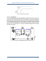
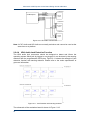
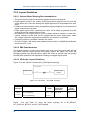
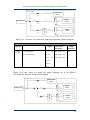
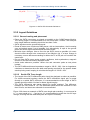
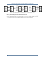
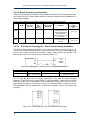
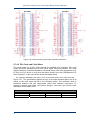
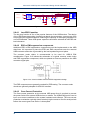
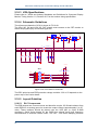
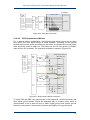
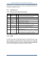
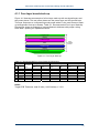
Figure 2-53 Serial Bus Connection
2.12.4.2
PS/2 Keyboard and Mouse
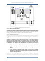
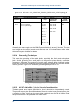
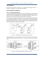
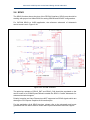
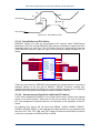
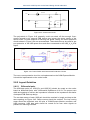
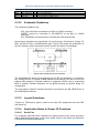
For a general design consideration, the keyboard and mouse should be far away
from audio and VGA signal traces to avoid crosstalk. According to the general
keyboard and mouse power specifications, the traces of keyboard and mouse power
trace should be routed to afford 1A. The power can be Vcc main power, or 5VSB if
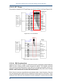
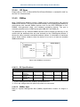
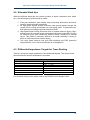
wake-up from S3 is needed. The reference schematic is shown in Figure 2-54.
COMExpress
Super
I/O
VCC
1A Trace Wide
Ferrite
Fuse 1A
Bead
Keyboard Connector
Mini-dim 6P
VCC
LPC_AD[0]
LPC_AD[1]
LPC_AD[2]
LPC_AD[3]
LPC_FRAME#
LPC_DRQ[0]
KBDAT
KBCLK
KB_DAT
KB_CLK
LPC_DRQ[1]
GND
LPC_SERIRQ
LPC_CLK
Digital Ground Chassis Ground
Mouse Connector
VCC
1A Trace Wide
Mini-dim 6P
Ferrite
Fuse 1A
MS_DAT
MS_CLK
Bead
VCC
MSDAT
MSCLK
GND
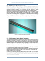
Figure 2-54 Keyboard and Mouse connection
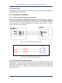
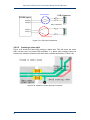
To avoid EMI and ESD, the ground plane of the keyboard / mouse connector and
other digital ground planes, should be separated with an isolation moat, which is
recommended to be at least 40 mils in width. Digital ground and chassis ground
should be connected via screw holes to assure the integrity of the ground plane.
59