1
Other PDRC 380 functions
The PRDC 380 does more than straightforward testing of RCDs.
Its other functions are:
A. Checking correct wiring condition of supply.
When the instrument is first switched on by pressing the ON/OFF
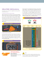
button, the three LEDs in the orange triangle will illuminate (fig 6) .
If all is in order, all three briefly show red, changing quickly to
green, back to red and then again to a steady green. This condition,
showing three green LEDs, indicates the correct wiring status. Any
other condition of the LEDs, together with a warbling tone, indicates
a fault condition, and do not proceed with further testing. The
customer should be notified of the problem, and they should seek
further advice.
6
Reversal of the live and neutral/earth connections at the incoming
mains supply is a very unusual, but very dangerous, fault. The
PDRC 380 will test to make sure that this dangerous misconnection
has not been made. To carry out the test, the orange area below
the TEST button, and labelled POLARITY TEST (4) should be
pressed and held for several seconds. Note that the area concerned
does not depress when pushed. In the event of the three LEDs
NOT being all green (fig. 8), do NOT proceed , and advise the
customer to urgently contact their Electricity Supplier.
8
Correct and reverse polarity displays
Correct wiring display
GOOD
Condition
Number
Wiring
Condition
POSSIBLE FAULT
Supply
Terminal
N
LED
Display
E
Buzzer
L
Socket Wiring
B. Supply voltage measurement.
As soon as the three green LEDs in the orange triangle are lit steadily, the
display will show the supply voltage (fig 7) . This should be compared
with the correct voltage range, shown on the instrument face directly
above the display. If the voltage displayed is too high or too low, the
customer should seek urgent help from their electricity supplier. Do not
proceed with further testing.
7
Supply voltage display
C. Polarity test.
1
Correct
N
E
L
Continuous
2
L-E reverse
N
L
E
Warble
3
L-N-E miswire
E
L
N
Warble
4
L-N reverse
L
E
N
Warble
5
L-N-E miswire
L
N
E
Warble
6
Faulty N / L-E miswire
NC
L
N
Warble
7
Faulty N / E miswire
NC
N
L
Warble
8
Faulty N
NC
E
L
Warble
9
Faulty N / L-E reverse
NC
L
E
Warble
10
Faulty E / L-N reverse
L
NC
N
Warble
11
Faulty E
N
NC
L
Warble
12
Faulty E / N miswire
E
NC
L
Warble
13
Faulty E / L-N miswire
L
NC
E
Warble
14
Faulty L / N-E miswire
L
N
NC
Warble
15
Faulty L / E miswire
N
L
NC
Warble
16
Faulty L / N-E miswire
E
L
NC
Warble
17
Faulty L / N miswire
L
E
NC
Warble
18
No Mains
NC NC NC
None
LED’s will flash to indicate fault condition
NC=No Connection
Socket & See Industrial
www.socketandsee.co.uk
Unit 4, Century Road,
High Carr Business Park,
Newcastle, Staffordshire, UK, ST5 7UG
T +44 (0)1782 567096
F +44 (0)1782 567095
NOTE:
This document is intended as a Guide to RCD Testing only and
reference should be made to the PDRC380 User Manual for full
operating instructions before any tests are undertaken.