1
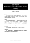
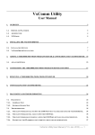
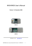
TM M2M-720-A User’s Manual Version 1.20 M2M-720-A User Manual (Version 1.20, Aug/2010) PAGE:1 Warranty All products manufactured by ICP DAS are under warranty regarding defective materials for a period of one year from the date of delivery to the original purchaser. Warning ICP DAS assumes no liability for damages resulting from the use of this product. ICP DAS reserves the right to change this manual at any time without notice. The information furnished by ICP DAS is believed to be accurate and reliable. However, no responsibility is assumed by ICP DAS for its use, or for any infringements of patents or other right of third parties resulting from its use. Copyright Copyright 2010 by ICP DAS. All rights are reserved. Trademark The names used for identification only may be registered trademarks of their respective companies. List of Revision Date 2010/08/16 Author Raiden M2M-720-A User Manual (Version 1.20, Aug/2010) Version 1.20 Revision Release PAGE:2 Table of Contents 1. Introduction…………………………………………………………... 4 1.1 Features ........................................................................................... 5 1.2 Hardware Specifications ................................................................. 6 2. Hardware……………………………………………………………... 8 2.1 Pin Assignment ............................................................................... 8 2.2 Wiring Instructions ......................................................................... 9 2.3 DIP switch and Trigger button...................................................... 12 2.4 LED Status Indicators ................................................................... 13 2.5 Communication Port ..................................................................... 14 3. Configuration and Operation with Web Browser……………………15 3.1 Connection Setting........................................................................ 15 3.2 Web Configuration—function menu............................................. 19 3.3 Web Configuration—setup page................................................... 21 4. Application………………………………………………………….. 45 4.1 Pair Connection............................................................................. 45 4.2 Broadcast Connection ................................................................... 46 4.3 ETM Operation ............................................................................. 47 5. VxComm Applications………………………………………………49 5.1 Introduction................................................................................... 49 5.2 Architecture................................................................................... 49 5.3 Installing the VxComm Driver...................................................... 50 5.4 VxComm communication test ...................................................... 53 6. Troubleshooting…………………………………………………….. 55 7. FAQ…………………………………………………………………. 56 8. Dimensions………………………………………………………….. 67 M2M-720-A User Manual (Version 1.20, Aug/2010) PAGE:3 1. Introduction The M2M-720-A module is specially designed for the remote maintenance solution with voice streaming. This module provides 2 major technologies on networking: Voice streaming and Pair connection functions. The Pair connection means that the user can operate remote COM port device via Ethernet TCP/IP protocol just like a local COM port and the Voice streaming means the user can talk to remote operator while operate remote COM-linked devices. Refer to the following graph. Furthermore, M2M720-A integrates the Virtual com technology. That can resolve the insufficiency of real com port in PC. By applying this technology, the maintenance man can take the remote maintenance or monitor whatever time or place. Figure 1: Voice streaming M2M-720-A User Manual (Version 1.20, Aug/2010) PAGE:4 Figure 2: Pair connection In the applications of M2M series of ICPDAS, it includes the server with one or more clients. If the system is applied in Internet, the server module needs a real IP to let the clients connect to. The setting of firewall or router is important for that. If in Intranet or local network, this issue is not to care. 1.1 Features ● ● ● ● ● ● ● ● ● ● Support voice streaming on network Provide pair connection (RS-232,RS-485) on network Support server and client function. Server mode can manage max 64 clients. (Clients can be M-4132, M2M-720-A, M2M-710D..) Support voice broadcast function in server mode. Support Virtual COM technology Web-based administration Linux 2.6 platform Support Static IP, DHCP, PPPoE protocols Provide dynamic DNS function to resolve the problem without the fixed M2M-720-A User Manual (Version 1.20, Aug/2010) PAGE:5 ● ● ● ● ● ● ● real IP. Provide event record and e-mail function Built-in web server, FTP server Built-in RTC Built-in self-tuner ASIC chip for RS-485 port Provide LED indicators Robust, fan less design CE/FCC, EMI, RoHS compliance 1.2 Hardware Specifications Item CPU Memory Ethernet Audio Com port Power requirement Description xScale PXA-255, 400 MHz processor SDRAM: 64 MB Flash: 32 MB SRAM: 256 KB Ethernet Speed: 10/100M Ethernet interface: RJ-45 connector Internet connection type: DHCP, Static IP, PPPoE Ethernet protocols & services: TCP/IP, Web server, FTP server, Telnet & ssh Provide microphone input and stereo speaker output Microphone and speaker interface: 3.5mm 3-pin phone jack Volume and tone quality adjustable Serial port - RS-232/RS-485 COM1:RS-232 interface -- 3-pin screw terminal block RS-232: TXD, RXD, GND COM2:RS-485 interface -- 2-pin screw terminal block RS-485: D+, D-, self-tuner ASIC inside Baud Rate: 1200/2400/4800/9600/19200/38400/57600/115200 bps Data Format: 5/6/7/8 data bits, None/Odd/Even parity bit, 1/2 stop bit Unregulated +10V ~ +30 VDC Power consumption 4.6 W M2M-720-A User Manual (Version 1.20, Aug/2010) PAGE:6 Environmental Dimensions Operating temperature: -20 ~ 60 ºC Storage temperature: -25 ~ 85 ºC CE/FCC, EMI, RoHS compliance 72 x 33 x 110 (mm) M2M-720-A User Manual (Version 1.20, Aug/2010) PAGE:7 2. Hardware 2.1 Pin Assignment Figure 3: Pin assignment of M2M-720-A Table 1: 9-pin screw terminal block Pin Name Description 1 Trig 2 T.Gnd GND of trigger input 3 RXD Rx of RS-232 4 TXD Tx of RS-232 5 GND GND of RS-232 6 D+ Data+ of RS-485 7 D- Data- of RS-485 8 PWR V+ of Power Supply (+10 to +30VDC) 9 GND GND of Power Supply Trigger input M2M-720-A User Manual (Version 1.20, Aug/2010) PAGE:8 Table 2: RJ-45 socket Pin Name Description 1 TX+ TX+ output 2 TX- TX- output 3 RX+ RX+ input 4 - N/A 5 - N/A 6 RX- 7 - N/A 8 - N/A RX- input Table 3: 3.5mm Phone Jack (Speaker Out) Pin Name Description 1 GND 2 Tip 3 - N/A 4 - N/A 5 Ring Ground Left channel Right channel Table 4: 3.5mm Phone Jack (Microphone In) Pin Name Description 1 GND 2 Tip 3 - N/A 4 - N/A 5 Ring Ground Input Signal Ground 2.2 Wiring Instructions The communication interface of M2M-720-A includes RS-232, RS-485 and Ethernet. The wiring instructions are described in section 2.2.1, 2.2.2 and 2.2.3. M2M-720-A User Manual (Version 1.20, Aug/2010) PAGE:9 2.2.1 RS-232 connection There are two types of RS-232 ports, DTE (Data Terminal Equipment, like M2M series, PC, Serial Printers, PLC and Video Cameras) and DCE (Data Circuit-Terminating Equipment, like modem) type, and that the signal names and pin numbers are the same, but signal flow is opposite! When connecting the M2M-720-A to a DCE device, the user just needs to match the signal names. When connecting the M2M-720-A to a DTE device, the user needs to use a crossover cable (TX crosses to RX, GND to GND,), as shown in the figure 4, 5. Figure 4: “3-wire” RS-232 (M2M-720-A to DTE) Figure5: “3-wire” RS-232 (M2M-720-A to DCE) M2M-720-A User Manual (Version 1.20, Aug/2010) PAGE:10 2.2.2 RS-485 connection The RS-485 wiring diagram is shown in figure 6. Figure 6: RS-485 connection 2.2.3 Ethernet connection The M2M-720-A module is based on a client-server architecture model. When the M2M-720-A works as a server in Internet, it should set the firewall before the M2M-720-A module appropriately or else the client will not connect to the server. Figure 7: Ethernet connection M2M-720-A User Manual (Version 1.20, Aug/2010) PAGE:11 2.3 DIP switch and Trigger button The M2M-720-A provides two switches (SW1, SW2) and a trigger button (TB). These switches and button can decide initial function of the system after power on and enable/disable the request to connect. The descriptions are shown in table 5, 6. Figure 8: DIP switch and Trigger Button Table 5: DIP switch and trigger button for initial function Option State Description SW2=ON SW1=ON To press the TB about 40 second after power on All system settings will be cleared and recover default settings. (Warning: it will not restore settings after clear) SW2= OFF IP recover default SW1= ON setting for this To press the TB about 40 time second after power on After power on, it will set IP to default setting (192.168.1.217) for this time, but it will restore original IP at next time. SW2= ON IP recover default SW1= OFF setting forever To press the TB about 40 second after power on After power on, it will set IP to default setting (192.168.1.217) and save to flash. Recover default setting forever M2M-720-A User Manual (Version 1.20, Aug/2010) PAGE:12 Option State Description Display the current IP and version SW2=OFF SW1=OFF To press the TB about 40 second after power on Normal setting The other states After power on, it will display the message about current IP and version information from Com Port (RS-232). Normal state; It will not change any setting and data. Table 6: DIP switch and trigger button for the request Option State SW2=OFF Disable the request SW1=OFF to connect Press the TB Enable the request to connect SW2=ON SW1=ON Press the TB Description Client: Send the request to disconnect. The voice and com port connection will be disconnected, but the login connection will hold on. Client: request server to connect. 2.4 LED Status Indicators The M2M-720-A provides three LEDs to indicate the status, as shown below. Figure 9: LED indicator M2M-720-A User Manual (Version 1.20, Aug/2010) PAGE:13 Table 7: LED status description Name Status Description on Power supply is ok. off Power supply has failed. PWR SA1 flash It is receiving com port data via Ethernet. Server: The Ethernet is initial ok and wait for the client to login. flash slowly SA2 flash fast on SA1 & SA2 Client: The Ethernet is initialized ok and login completely. It has readied to enable voice and com port data connection by the server. It is sending or receiving voice data via Ethernet. There are happening some errors. (Client: Please check settings about IP & DNS) flash slowly (SA1 It is trying to establish the connection with the server/client. If it can’t & SA2 flash at connect to the server/client for a long time, please check that the M2Mthe same time) 720-A has available network settings and is working well on Ethernet. flash (SA1 & SA2 alternate flash) Server: Receive the request to connect from the client. Client: Request server to connect. 2.5 Communication Port M2M-720-A uses several communication ports of Ethernet, as shown in the below. If the user connects M2M-720-A client by “ETM operation mode”, the communication ports will include the ports of “ETM configuration file”. Table 8: Communication Port Service Web Server FTP Server Telnet Server SSH Server E-mail function VSoIP function VxComm function Port number 80 21 23 22 587 443 10000, 10001 M2M-720-A User Manual (Version 1.20, Aug/2010) note default default PAGE:14 3. Configuration and Operation with Web Browser The M2M-720-A module is built-in web server, the user can configure and operate the M2M-720-A by web browser (ex: IE). 3.1 Connection Setting Before you open the web browser to configure the module, it needs to connect the M2M-720-A and your PC to the same sub network or same Ethernet Switch (as shown in figure 10) and set network settings (such as IP/Mask/Gateway) of the PC. The example of connection setting will describe below and Microsoft Windows XP Professional SP2 is used. Figure 10: connection architecture Connection steps: Step 1: Open Network Connections 1.Click “start->Settings->Network Connections” M2M-720-A User Manual (Version 1.20, Aug/2010) PAGE:15 Figure 11: click “start->Settings->Network Connections” 2. Double click “Local Area Connection” icon 3. click “Properties” button Figure 12: click “Properties” button M2M-720-A User Manual (Version 1.20, Aug/2010) PAGE:16 4. Select “Internet Protocol(TCP/IP)” and click “Properties” button Figure 13: click “Properties” button Step 2: Set “Internet Protocol Properties” and then click “OK” button. The settings must have the same domain and different IP with the M2M720-A. (ex: M2M-720-A’s default IP = 192.168.1.217, PC’s IP = 192.168.1.210). Figure 14: set “Internet Protocol Properties” M2M-720-A User Manual (Version 1.20, Aug/2010) PAGE:17 Step 3: test connection 1. Click “start->Run...” Figure 15: click “start->Run...” 2. Key in “cmd” and then click ”OK” button Figure 16: key in “cmd” and then click ”OK” button 3. key in “ping 192.168.1.217” and click “Enter”. If the response message shows “Request timed out”(figure 17), it means the network settings between PC and the module are not correct. Please check the network is available and the settings are all correct. M2M-720-A User Manual (Version 1.20, Aug/2010) PAGE:18 Figure 17: Ping IP Error If the network settings are correct, it will show “Packets: Sent=4, Received=4, Lost=0“(figure 18). Figure 18: Ping IP OK 3.2 Web Configuration—function menu Now the PC is set completely and working well with the M2M-720-A. M2M-720-A User Manual (Version 1.20, Aug/2010) PAGE:19 Please open web browser (ex: IE, Mozilla, etc.) on PC and key in http://192.168.1.217/main.htm in the Address line and then press “Enter” key to link the M2M-720-A, as shown in figure 19. Figure 19: Web Configuration page When the browser connects with the M2M-720-A, Figure 19 is the first page. The left side is the function menu and the other is the setup page in the first page. Server and Client are different in the function menu, as shown in the below. Function menu (Server)-z Login z User Account z Date/Time Config z Standard Config z DDNS Config z Com Port Config z Audio Config z Etm Config z Comm Operation M2M-720-A User Manual (Version 1.20, Aug/2010) PAGE:20 z z z z z z Etm Operation Webcam Event Log Event Report Network Tools Information Reboot Function menu (Client)-z Login z User Account z Date/Time Config z Standard Config z Com Port Config z Audio Config z Comm Operation z Etm Operation z Network Tools z Information Reboot The “Reboot” button can provide the user to restart the M2M-720-A. 3.3 Web Configuration—setup page 1、Login:The user login and logout interface Figure 20: user login page M2M-720-A User Manual (Version 1.20, Aug/2010) PAGE:21 Figure 21: user logout page 2、User Account:The user account setting limits which user can configure the module settings. The super user (Account 1, name=”root”, password=”icpdas”) is an only the user that can edit this page. Figure 22: User Account page 3、Date/Time Config:The Date and Time of M2M-720-A can be set via “Date/Time Config” page. The format of date is “Year(4 digits)/Month(2 digits)/Day(2 digits)” and the time is “Hour(2 digits):Minute(2 digits):Second(2 digits)”. The user can get current date and time of M2M-720-A by click “Refresh” button and set date and time from the PC by click “Setting” button. M2M-720-A User Manual (Version 1.20, Aug/2010) PAGE:22 Figure 23: System Time page 4、Standard Config: When changing the setting in this page, the user must restart the M2M-720-A to enable new settings. 1. System a. Operation Mode:VSoIP Server / VSoIP Client。 The M2M-720-A has 2 operation modes. They are “VSoIP Server” and “VSoIP Client”. The user can set the M2M720-A to be a server or client in this page. When the M2M-720-A plays the role of client, it will try to connect with the server after starting. When the M2M-720-A plays the role of server, it will wait client to link. 2. NetWork a. Host Name:The module name. It can be recognized when operation. b. Connect to Server by:IP / DNS The setting can provide the client to connect with the server by IP or DNS of the server c. ServerIP:The user can set the IP address of the server that the client wants to connect to. d. ServerDNS:The user can set the DNS of the server that the client wants to connect to. e. Communication Port:The user can set the port number of the server that the client want to link in this setting. The default is “443”. M2M-720-A User Manual (Version 1.20, Aug/2010) PAGE:23 f. Boot Protocol:Static IP / DHCP / ADSL Connection M2M-720-A supports three kinds of getting IP modes, they are “Static IP”, “DHCP” and “PPPoE (ADSL)”. The user can choose one of these modes to set the IP address of M2M-720-A when booting. 3. Static IP Config a. IP Address:When Boot Protocol is “Static IP”, the user can set IP address of M2M-720-A in this field. b. NetMask:When Boot Protocol is “Static IP”, the user can set subnet mask of M2M-720-A in this field. c. GateWay:When Boot Protocol is “Static IP”, the user can set gateway of M2M-720-A in this field. d. DNS Server:When Boot Protocol is “Static IP”, the user can set DNS server of M2M-720-A in this field 4. ADSL Config:When Boot Protocol is “ADSL”, the user needs to set “user name” and “password” for ADSL connection. The user can get the “user name” and “password” from your ISP (Internet Service Provider). M2M-720-A User Manual (Version 1.20, Aug/2010) PAGE:24 Figure 24: Standard Config page 5、DDNS Config:When the M2M-720-A plays the role of server and Boot Protocol isn’t “Static IP”, the client may not connect with the server, because the IP address of the server is floating, not static. We provide a solution for this situation. That is DDNS service. When IP address of the server is changed, the server will register current IP to website that provides DDNS service. The client can connect with the server by domain name that the user registers. NOTE: Every company that provides DDNS service has different way to register. In order to make it correctly work, we recommend the user to use DDNS service that the DynDNS Company provide. DynDNS website: http://www.dyndns.com/. 1. Create your Dynamic DNS account M2M-720-A User Manual (Version 1.20, Aug/2010) PAGE:25 a. Please open web browser (ex: IE, Mozilla, etc.) on PC and key in http://www.dyndns.com/ in the Address line and then press “Enter” key. b. Key in “user name” and “password” and click “Login” button. If the user has not created user account, please click “Create Account” Hyperlink to create user account and then login user account. Figure 25: DynDNS home page c. Click “Services” Hyperlink to enter Services page Figure 26: click ”Services” Hyperlink M2M-720-A User Manual (Version 1.20, Aug/2010) PAGE:26 d. Click “Dynamic DNS” Hyperlink to enter Dynamic DNS page Figure 27: click ” Dynamic DNS” Hyperlink e. Click “Get Started” button Figure 28: click ”Get Started” button f. Key in and select your hostname (ex: icpdas.home linux.com ), and key in IP address of the server. Don’t care the other settings and click “Create Host” button. M2M-720-A User Manual (Version 1.20, Aug/2010) PAGE:27 Figure 29: Add New Hostname Figure 30: Create New hostname success 2. DDNS Config: a. DDNS:Disable / Enable The user can Enable or Disable DDNS function by this setting. b. Host Name:It is the hostname that user creates in DynDNS website (ex:icpdas.homelinux.com). c. User Name:It is the name of the user account in DynDNS website. d. Password:It is the password of the user account in DynDNS website. M2M-720-A User Manual (Version 1.20, Aug/2010) PAGE:28 Figure 31: DDNS Config page 6、Com Port Config:The user can set com port setting of M2M720-A in this page. If com port setting of the server and client is different, Com port setting of the client will be covered by the server. When the user changes the setting in this page, the user must restart the M2M-720-A to active the new setting. 1. Local Port:RS232 / RS485 / VxComm Select local com port connection from RS-232 or RS-485 or VxComm. 2. Remote Port:RS232 / RS485 / VxComm Select remote com port connection from RS-232 or RS-485 or VxComm. This setting is used for VSoIP_Server. 3. Baud Rate:1200 / 2400 / 4800 / 9600 / 19200 / 38400 / 57600 / 115200 / 230400 bps 4. Data Bits:5 / 6 / 7 / 8 data bits 5. Parity:None / Odd / Even / Space 6. Stop Bits:1 / 2 stop bits 7. Flow Control:None / Hardware / XonXoff M2M-720-A User Manual (Version 1.20, Aug/2010) PAGE:29 Figure 32: Com Port Config page 7、Audio Config:The user can set the Audio quality, output volume and input volume in this page. When the audio quality is bad, the user can turn audio quality, output volume and input volume between the server and client to improve. 1. Quality:2~10 Select the audio quality, including sample rate and sample resolution. The best quality is 10. 2. Output Volume:0~10 The maximum output volume is 10. 3. Input Volume:0~10 The maximum input volume is 10. Figure 33: Audio Config page M2M-720-A User Manual (Version 1.20, Aug/2010) PAGE:30 8、ETM Config:The user can set ETM settings of M2M-720-A in this page for Ethernet through mode. 1. Target IP: Set IP address of the target device (ex: PLC). M2M-720-A client will connect to target device by this IP. 2. Configure file:Configure1~8 Select configuration file. When the M2M-720-A server, client and target device operate at ETM operation mode, they will connect by the configuration file. 3. Start value of port scan:1~65535 4. Stop value of port scan:1~65535 5. Save Setting:Save current settings. 6. Default Setting:Load default settings. 7. Port Setting:The user can link “Port Setting” page by this button. The description is shown below about “Port Setting” page. a. Configure file:Select configuration file. b. Show:Show the content of the configuration file c. Set:Set the content of the configuration file d. Return:Return to the “Etm Config” page. e. Configuration:The content of the configuration file is shown here. “Target Port” means the communication port of the target device. “Communication Port” means the communication port of M2M-720-A. 8. Port Scan:The user can link “Port Scan” page by this button. The description is shown below about “Port Scan” page. a. Target IP:Show IP address of the target device (ex: PLC). b. Port Range:Show the range of port scan. c. Save result to:Select configuration file that the user wants to save. d. Scan result:Show the result of port scan. e. Login list:This item can show the name of client that M2M-720-A User Manual (Version 1.20, Aug/2010) PAGE:31 login completely. f. Start Scan:Start “Port Scan” function. Before the user clicks “Start Scan” button, the user needs to select client device at “Login list”. After the user clicked “Start Scan” button, the “Start Scan” button will become to “Stop Scan” button and M2M-720-A will enable “Port Scan” function. After the procedure of “Port Scan” finished, the “Stop Scan” button will become to “Start Scan” button again. g. Return:Return to the “Etm Config” page. Figure 34: Etm Config page Figure 35: Port Setting page M2M-720-A User Manual (Version 1.20, Aug/2010) PAGE:32 Figure 36: Port Scan page 9、Comm Operation:The user can use or test voice and com port transmission functions in this page. 1. Communication configure : The user can select communication parameters in this page. The parameters are effective in this current connection, but it will not change the system settings. a. Quality:2~10 Select the audio quality. b. Local Port:RS232/RS485/VxComm Select local com port connection from RS-232 or RS-485 or VxComm. c. Remote Port:RS232/RS485/VxComm Select remote com port connection from RS-232 or RS485 or VxComm. This setting is used for VSoIP_Server. M2M-720-A User Manual (Version 1.20, Aug/2010) PAGE:33 d. Baud Rate:1200 / 2400 / 4800 / 9600 / 19200 / 38400 / 57600 / 115200 / 230400 bps Select baud rate of com port. e. Data Bits:5 / 6 / 7 / 8 data bits Select data bits of com port. f. Parity:None / Odd / Even / Space Select parity of com port. g. Stop Bits:1 / 2 stop bits Select stop bits of com port. h. Flow Control:None / Hardware / XonXoff Select flow control of com port. i. GetStatus : The user can get current communication parameters from this button. j. SetStatus : The user can set current communication parameters from this button. 2. Operation:The settings will only show in page of the server. If you want to refresh the status in this page, you can click “GetStatus” button. a. Your Status:Show status of M2M-720-A z Idle Mode: The voice and com port connection have not established yet. z Broadcast Connection Mode: All clients will hear the voice from microphone of the server via Ethernet. z Broadcast & Pair Mode: Server and client that the user selected will setup a virtual channel over Ethernet that allow bi-directional voice and serial (RS232 or RS485) data to pass through and the other client will also hear the voice from microphone of the server. M2M-720-A User Manual (Version 1.20, Aug/2010) PAGE:34 z Pair Connection Mode: Server and client that the user selected will setup a virtual channel over Ethernet that allow bi-directional voice and serial (RS232 or RS485) data to pass through. z ETM Connection Mode: Server and client that the user selected will setup a virtual channel over Ethernet that allow bi-directional voice and Ethernet data to pass through. z ETM Scan Mode: Server and client will scan target device (ex: PLC) that the user selected to get the port settings. b. Request connection list:This item can show the name of client that send out the communication request. c. Login list:This item can show the name of client that login completely. d. “Pair Connection” button : The user can send “Pair Connection” command to M2M-720-A by this button. The user must select the name of the client from “Login list” before click this button. e. “Broadcast Connection” button : The user can send “Broadcast Connection” command to M2M-720-A by this button. f. “Broadcast & Pair” button:The user can send “Broadcast & Pair Connection” command to M2M-720-A by this button. The user must select name of the client from “Login list” before click this button. M2M-720-A User Manual (Version 1.20, Aug/2010) PAGE:35 g. “Drop Client” button : The user can cancel “Pair Connection” command and return to “Broadcast Connection” mode by this button. h. “Request Break” button:The user can cancel all audio and com port connections by this button. PS:Server can accept a maximum of 64 clients to login. When Server is at “Broadcast Connection” mode or “Broadcast & Pair” mode, we recommend that server must not login to exceed 32 clients, because it will make an intermittent audio transmission. Figure 37: Comm Operation page 10、Etm Operation:The user can use or test voice and Ethernet through functions in this page. 1. Communication configure : The user can select communication parameters in this page. The parameters are effective in this current connection, but it will not change M2M-720-A User Manual (Version 1.20, Aug/2010) PAGE:36 the system settings. a. Quality:2~10 Select the audio quality. b. Target IP: Set IP address of the target device (ex: PLC). M2M-720-A client will connect to target device by this IP. c. Configure file:Configure1~8 Select configuration file. When the M2M-720-A server, client and target device operate at ETM operation mode, they will connect by the configuration file. d. GetStatus : The user can get current communication parameters from this button. e. SetStatus : The user can set current communication parameters from this button. 2. Operation:The settings will only show in page of the server. If you want to refresh the status in this page, you can click “GetStatus” button. a. Your Status:Show status of M2M-720-A. Please refer to section 3.3 “Web Configuration” Î “Comm Operation” page for detail. b. Request connection list:This item can show the name of client that send out the communication request. c. Login list:This item can show the name of client that login completely. d. “Pair Connection” button : The user can send “Pair M2M-720-A User Manual (Version 1.20, Aug/2010) PAGE:37 Connection” command to M2M-720-A by this button. The user must select the name of the client from “Login list” before click this button. e. “Request Break” button:The user can cancel all audio and data connections by this button. Figure 38: Etm Operation page 11、Webcam:The settings will only show in the web page of the server. When the server connected with client by Pair Connection mode and the client has video interface, the user can click “Remote Image” to watch the live image of the client. Note1: M2M-720-A has no video interface. Note2: The user must setup JRE (Java Runtime Environment, it can be downloaded from http://java.sun.com/javase/downloads/index.jsp) firstly to show image on PC. Figure 39: Webcam page M2M-720-A User Manual (Version 1.20, Aug/2010) PAGE:38 Figure 40: Remote Image page 12、Event Log:It will show the event log that clients login and connection break. To clear the event log can click “Clear Log” button. Figure 41: Event Log page M2M-720-A User Manual (Version 1.20, Aug/2010) PAGE:39 13、Event Report:The page provides the server sending “Event Log” to user by e-mail. It uses SMTP protocol to provide mail service. 1. Function:Disable / Enable The user can Enable or Disable “Event Report” function by this setting. It must finish setting mail server before enable this function, else event log will not be sent to the user’s mailbox correctly. 2. Report Cycle:every month / every week / every day Select report period from every month, every week or every day. 3. Report Date for monthly:1~31 Set report date, when report cycle is every month. 4. Report Date for weekly:Monday ~ Sunday Set report date, when report cycle is every week. 5. Report Time:00:00 ~ 23:59 Set report time. The format is “Hour (2 digits):minute (2 digits)”. 6. “Save Setting” button:For saving the settings. 7. “Default Setting” button:For getting the default settings. 8. “Mail Server Setting” button:The user can link “Mail Server Setting” page by this button. The description is shown below about “Mail Server Setting” page. a. Mail Server:Set URL of mail server. Mail server is “smtp.gmail.com”, if you use Gmail. M2M-720-A User Manual (Version 1.20, Aug/2010) PAGE:40 b. Mail Port:Set port number of mail server. Mail port is “587”, if you use Gmail. c. Mail To:Set mail address that receive event report (ex: ****@gmail.com). d. Mail From:Set mail address that the user create at Gmail (ex: ****@gmail.com). e. Authentication Method:None / AUTH LOGIN / AUTH PLAIN Select Authentication method. Authentication method is “AUTH LOGIN”, if you use Gmail. f. User Name:Set the user name for sign in to mail server with your account. g. Password:Set the password for sign in to mail server with your account. h. TLS/SSL Certification:Enable / Disable Select enable or disable TLS/SSL certification. It is Enable, if you use Gmail. i. “Save Setting” button:For saving the settings. j. “Default Setting” button:For getting the default settings. k. “SendMail test” button : For testing the mail server settings. If they are all correct, it will show “Send Mail success” message after the user click the button. l. “Return” button:Return to the “Event Report” page. M2M-720-A User Manual (Version 1.20, Aug/2010) PAGE:41 Figure 42: Event Report page Figure 43: Mail Server Setting page 14、Network Tools: 1. Ping Command:This command can help user to test the network ability. 2. ARP Command:This command can display the system ARP cache 3. TraceRoute Command:This command can help user to trace the route IP packets follow going to ‘device’. M2M-720-A User Manual (Version 1.20, Aug/2010) PAGE:42 Figure 44: Network Tools page Figure 45: Ping Command page Figure 46: ARP Command page M2M-720-A User Manual (Version 1.20, Aug/2010) PAGE:43 Figure 47: Trace Route Command page 15、Information: 1. OS Version:Show OS version. 2. Firmware Version:Show application program version. 3. Current IP:Show current IP. 4. Subnet Mask:Show current subnet mask. 5. Mac Address:Show current Mac address. 6. License Verify:Show the result that the license is verified. If it shows “OK”, it means the licence is passed. Figure 48: Information page M2M-720-A User Manual (Version 1.20, Aug/2010) PAGE:44 4. Application 4.1 Pair Connection A server can accept one or more clients to login, but a server can only connect with a client in pair connection mode. In this mode, two M2M720-As which are setting as Server and Client separately setup a virtual channel over Ethernet or Internet that allow bi-directional voice and serial (RS-232 or RS-485) data to pass through, as shown in figure 49, 50. Figure 49: Pair connection (one server to one client) M2M-720-A User Manual (Version 1.20, Aug/2010) PAGE:45 Figure 50: Pair connection (one server to more clients) 4.2 Broadcast Connection A server can connect with one or more clients in this application. Voice collected from the server’s MIC will transfer to all clients’ speakers over Ethernet or Internet M2M-720-A User Manual (Version 1.20, Aug/2010) PAGE:46 Figure 51: Broadcast connection 4.3 ETM Operation A server can accept one or more clients to login, but a server can only connect with a client in this mode. Two M2M-720-As which are setting as Server and Client separately setup a virtual channel over Ethernet or Internet that allow bi-directional voice and Ethernet data to pass through, as shown in the below. In this mode, the user’s application programming (ex: PLC editor) can connect to remote device (ex: PLC) by server and client. The remote device doesn’t need any real IP at this application. M2M-720-A User Manual (Version 1.20, Aug/2010) PAGE:47 Figure 52: ETM Operation M2M-720-A User Manual (Version 1.20, Aug/2010) PAGE:48 5. VxComm Applications 5.1 Introduction Using the VxComm (Virtual Com) technology, PC can create virtual Com Ports to map the Com Port of the M2M-720-A. To use the VxComm application, users must install a VxComm Driver first. After installation, users can operate the virtual Com Port as a real Com Port in PC to access the serial devices connects to the M2M-720-A. By doing this, you can operate the remote com port whatever and whenever you are. 5.2 Architecture In Pair connection mode the user can operate the virtual Com Port to access the serial device connects to the M2M-720-A Client. Figure 53: VxComm Applications M2M-720-A User Manual (Version 1.20, Aug/2010) PAGE:49 5.3 Installing the VxComm Driver Step 1: The installation software can be obtained from the following location ftp://ftp.icpdas.com/pub/cd/8000cd/napdos/driver/vxcomm_dri ver/ Please choose the latest version that suits your Windows operation system. VxComm2K_v2.9.9_setup.exe for Windows NT4.0, 2000 /XP/2003 and Vista32 (32-bit) VxComm98.exe for Windows 95/98/ME Step 2: Go the where you download the installation file, and then double-click the file in Windows to execute it. Figure 54: VxComm Driver install Step 3: From the Windows Start Menu, go to Program/ICPDAS /VxComm2K/ and click the VxComm Utility. M2M-720-A User Manual (Version 1.20, Aug/2010) PAGE:50 Figure 55: VxComm Utility location Step 4: Search and add M2M-720-A to VxComm Server. Figure 56: Search and add M2M-720-A VxComm Server Step 5: Double click Port1 to open “Port Configuration” dialog and select an appropriate Com Port number. M2M-720-A User Manual (Version 1.20, Aug/2010) PAGE:51 Figure 57: Select Com Port number Step 6: Reset VxComm Driver to make the settings effectively Figure 58: Reset VxComm Driver M2M-720-A User Manual (Version 1.20, Aug/2010) PAGE:52 5.4 VxComm communication test Step 1: Connect M2M-720-A Server, Client and PC, as shown below. Figure 59: Communication Architecture Step 2: Configure M2M-720-A Server’s Port1 to PC’s Com2 by VxComm Utility, please refer to section 5.3 for detail. Step 3: Set “Local Port” = VxComm, “Remote Port” = RS232, select M2M-720-A Client and then click “Pair Connection” button to connect M2M-720-A Server and Client by web page of M2M720-A Server. Figure 60: Web page settings M2M-720-A User Manual (Version 1.20, Aug/2010) PAGE:53 Step 4: Here we use Send232 Application (the user can download Send232 from http://ftp.icpdas.com/pub/cd/8000cd/napdos /7188e/tcp/pcdiag/source/send232.vb6_2.0.1) to test VxComm communication. Please open 2 Send232 Applications. One uses Com1 (connect with M2M-720-A Client), the other uses Com2 (provide by VxComm driver). When the user clicks “Send” button to send the message, the receive text box of the other will show the message. Figure 61: Communication test M2M-720-A User Manual (Version 1.20, Aug/2010) PAGE:54 6. Troubleshooting The troubleshooting list can help users to resolve the problems when using the M2M-720-A. If the problem still can't be solved, please contact with the technical staff of ICP DAS. Table 9 Errors and solutions Item Trouble state 1 2 Solution The power supply of M2M-720-A has some PWR LED indication of problems. Please check the wire connection of M2M-720-A is always turned the power and the voltage is between off 10~30VDC. SA1 and SA2 of M2M-720-A is always turned on Application program has some errors. Please reset the M2M-720-A and check licence whether it is OK or not in “information” page. Client: Please check server’s DNS and network settings whether they are all correct or not in “Standard Config” page. 3 It means M2M-720-A can’t establish the connection with the other M2M-720-A. SA1 and SA2 LED of M2M- Please check the network settings and M2M720-A flash slowly at the 720-A is working well on Ethernet. same time and keep the state long Client: Please check server’s IP/DNS and network settings whether they are all correct or not in “Standard Config” page. 4 Please turn audio quality, output volume and The audio quality of M2Minput volume of server and client in “Audio 720-A is bad. Config” page. 5 Please check the settings whether they are all M2M-720-A can’t send event correct or not in “Event Report” and “Mail report. Server Setting” page. M2M-720-A User Manual (Version 1.20, Aug/2010) PAGE:55 7. FAQ Q1: If I forget the M2M-720-A’s IP, how can I set and operate the M2M720-A by web browser? A1: You should get M2M-720-A’s IP first. It has two ways to get the IP, as shown below. I. Recover default IP provisionally. Step 1: Connect PC and the M2M-720-A by Ethernet Switch. Step 2: Set SW1=ON, SW2=OFF. Step 3: Press the Trigger Button about 40 second after power on. Step 4: M2M-720-A’s IP should be returned to “192.168.1.217”. Please set PC’s Network settings. The settings must have the same domain and different IP with the M2M-720-A (ex: IP=192.168.1.210, mask=255.255.255.0). M2M-720-A User Manual (Version 1.20, Aug/2010) PAGE:56 Step 5: Open web browser on PC and key in http://192.168.1.217/main.htm in the Address line. Step 6: If the connection is ok, it will show “login” page at web browser. Current IP is provisional, the user can refer to the user manual section 3.3 to login and then set network setting of M2M-720-A at “Standard Config” page. M2M-720-A User Manual (Version 1.20, Aug/2010) PAGE:57 II. Print current IP from Com Port (RS-232). Step 1: Connect PC and the M2M-720-A by RS-232 cable. Step 2: Open Com Port program. We used “Hyper Terminal” of Microsoft Window XP to test here. Step 3: Set communication setting of Com Port. (baud rate = 115200, data bits=8, parity=none, stop bits=1, flow control=none). M2M-720-A User Manual (Version 1.20, Aug/2010) PAGE:58 Step 4: Press Call icon. Step 5: Set SW1=OFF, SW2=OFF. Step 6: Press the Trigger Button about 40 second after power on. M2M-720-A User Manual (Version 1.20, Aug/2010) PAGE:59 Step 7: It will show M2M-720-A’s IP in “Hyper Terminal”(ex: IP Address = 192.168.0.211). Step 8: Connect PC and the M2M-720-A by Ethernet Switch. Step 9: Please set PC’s Network settings. The settings must have the same domain and different IP with the M2M-720-A (ex: IP=192.168.0.210, mask=255.255.255.0). M2M-720-A User Manual (Version 1.20, Aug/2010) PAGE:60 Step 10: Open web browser on PC and key in http://ip/main.htm (ex: http://192.168.0.211/main.htm) in the Address line. Step 11: If the connection is ok, it will show “login” page at web browser. Q2: Client can not connect to Server. A2: Please follow the following steps to check that the network configuration is correct. Step 1: Check IP of Server and Client is the only. The IP is not the same with the other network device. M2M-720-A User Manual (Version 1.20, Aug/2010) PAGE:61 Step 2: Please confirm the network configurations are correct. The configurations include IP Address, Net Mask, Gateway and DNS Server. If the configurations are all correct, it should respond to the ping command from PC (PC’s network setting must have the same domain with the Server and Client, the user can refer to user manual section 3.1 about ping IP). Step 3: Please confirm that the following settings are correct. ¾ “Server IP(*)” of Client is the same with “IP Address” of Server. ¾ “Communication Port” of Server and Client are the same. ¾ “Operation Mode” of Client is “VSoIP Client”. ¾ “Operation Mode” of Server is “VSoIP Server”. M2M-720-A User Manual (Version 1.20, Aug/2010) PAGE:62 Client’s “Standard Config” page Server’s “Standard Config” page Step 4: If Client connects to Server via internet, please confirm there is not any firewall before the Server and check network of Server and Client are available. The user can open web browser and key in http://ip/cgibin/Ping.cgi (ex: http://192.168.0.211/cgi-bin/Ping.cgi) in the Address line and press “Start” button to test the network. If the network is available, it will show “0% packet loss”. M2M-720-A User Manual (Version 1.20, Aug/2010) PAGE:63 Q3: Server and Client can’t establish Com Port connection. A3: Please follow the steps to check below. Step 1: Confirm Client has already login the Server and the user can find the host name of Client in the “Login list” at Server’s “Operation Mode” page.. Step 2: Confirm Server and Client are at “Pair Connection” mode and it shows “Your Status: Pair Connection with Client (IP)” at Server’s “Operation Mode” page. M2M-720-A User Manual (Version 1.20, Aug/2010) PAGE:64 Step 3: Confirm that the Com Port device is connected with Server and Client has the same communication settings with Server’s “Operation Mode” page. If it is different, please break the connection and change the settings then reconnect the client. Server’s “Operation Mode” page Step 4: Confirm the Cable connected Server/Client to Com Port device is wired correctly. If the connection is RS485, the user M2M-720-A User Manual (Version 1.20, Aug/2010) PAGE:65 can refer to user manual section 2.2.2. If the connection is RS-232 and the Com Port device is a data circuit-terminating equipment (DCE), the user just needs to match the signal names to connect Server/Client to Com Port device, else the user needs to use a crossover cable to connect. Some Com Port devices will wait for one of the handshaking lines to go to the correct level forever. Depending on the signal state it might sometimes work, other time it might not. Here, we connect the M2M-720-A and the Com Port device via handshake looped to avoid the Com Port device waits handshake line signals, as shown in below. M2M-720-A User Manual (Version 1.20, Aug/2010) PAGE:66 8. Dimensions M2M-720-A User Manual (Version 1.20, Aug/2010) PAGE:67 M2M-720-A User Manual (Version 1.20, Aug/2010) PAGE:68